JP3662672B2 - Container for dispensing flowable material - Google Patents
Container for dispensing flowable materialDownload PDFInfo
- Publication number
- JP3662672B2 JP3662672B2JP15686796AJP15686796AJP3662672B2JP 3662672 B2JP3662672 B2JP 3662672B2JP 15686796 AJP15686796 AJP 15686796AJP 15686796 AJP15686796 AJP 15686796AJP 3662672 B2JP3662672 B2JP 3662672B2
- Authority
- JP
- Japan
- Prior art keywords
- bush
- piston
- container
- neck
- container according
- Prior art date
- Legal status (The legal status is an assumption and is not a legal conclusion. Google has not performed a legal analysis and makes no representation as to the accuracy of the status listed.)
- Expired - Lifetime
Links
- 239000000463materialSubstances0.000titleclaimsdescription22
- 230000009969flowable effectEffects0.000titleclaimsdescription9
- 238000002347injectionMethods0.000claimsdescription17
- 239000007924injectionSubstances0.000claimsdescription17
- 230000004323axial lengthEffects0.000claimsdescription11
- 238000003780insertionMethods0.000claimsdescription9
- 230000037431insertionEffects0.000claimsdescription9
- 238000007689inspectionMethods0.000claimsdescription3
- 239000012530fluidSubstances0.000claims1
- 210000003739neckAnatomy0.000description39
- 210000003811fingerAnatomy0.000description6
- 238000000071blow mouldingMethods0.000description4
- 238000009826distributionMethods0.000description4
- 210000003813thumbAnatomy0.000description3
- 230000015572biosynthetic processEffects0.000description2
- 238000011049fillingMethods0.000description2
- 238000004519manufacturing processMethods0.000description2
- 230000001012protectorEffects0.000description2
- 239000003708ampulSubstances0.000description1
- 230000008859changeEffects0.000description1
- 239000003814drugSubstances0.000description1
- 229940079593drugDrugs0.000description1
- 239000007788liquidSubstances0.000description1
- 238000000034methodMethods0.000description1
- 238000012986modificationMethods0.000description1
- 230000004048modificationEffects0.000description1
- 238000000465mouldingMethods0.000description1
- 230000002093peripheral effectEffects0.000description1
- 238000002360preparation methodMethods0.000description1
- 230000001681protective effectEffects0.000description1
- 230000009467reductionEffects0.000description1
- 230000000717retained effectEffects0.000description1
- 238000007789sealingMethods0.000description1
- 238000007493shaping processMethods0.000description1
- 239000007921spraySubstances0.000description1
- 230000007704transitionEffects0.000description1
- 239000012780transparent materialSubstances0.000description1
Images


Classifications
- A—HUMAN NECESSITIES
- A61—MEDICAL OR VETERINARY SCIENCE; HYGIENE
- A61M—DEVICES FOR INTRODUCING MEDIA INTO, OR ONTO, THE BODY; DEVICES FOR TRANSDUCING BODY MEDIA OR FOR TAKING MEDIA FROM THE BODY; DEVICES FOR PRODUCING OR ENDING SLEEP OR STUPOR
- A61M5/00—Devices for bringing media into the body in a subcutaneous, intra-vascular or intramuscular way; Accessories therefor, e.g. filling or cleaning devices, arm-rests
- A61M5/178—Syringes
- A61M5/28—Syringe ampoules or carpules, i.e. ampoules or carpules provided with a needle
- A61M5/281—Syringe ampoules or carpules, i.e. ampoules or carpules provided with a needle using emptying means to expel or eject media, e.g. pistons, deformation of the ampoule, or telescoping of the ampoule
- A61M5/282—Syringe ampoules or carpules, i.e. ampoules or carpules provided with a needle using emptying means to expel or eject media, e.g. pistons, deformation of the ampoule, or telescoping of the ampoule by compression of deformable ampoule or carpule wall
- A—HUMAN NECESSITIES
- A61—MEDICAL OR VETERINARY SCIENCE; HYGIENE
- A61M—DEVICES FOR INTRODUCING MEDIA INTO, OR ONTO, THE BODY; DEVICES FOR TRANSDUCING BODY MEDIA OR FOR TAKING MEDIA FROM THE BODY; DEVICES FOR PRODUCING OR ENDING SLEEP OR STUPOR
- A61M5/00—Devices for bringing media into the body in a subcutaneous, intra-vascular or intramuscular way; Accessories therefor, e.g. filling or cleaning devices, arm-rests
- A61M5/178—Syringes
- A61M5/31—Details
- A61M2005/3117—Means preventing contamination of the medicament compartment of a syringe
- A61M2005/3118—Means preventing contamination of the medicament compartment of a syringe via the distal end of a syringe, i.e. syringe end for mounting a needle cannula
- A61M2005/312—Means preventing contamination of the medicament compartment of a syringe via the distal end of a syringe, i.e. syringe end for mounting a needle cannula comprising sealing means, e.g. severable caps, to be removed prior to injection by, e.g. tearing or twisting
- A—HUMAN NECESSITIES
- A61—MEDICAL OR VETERINARY SCIENCE; HYGIENE
- A61M—DEVICES FOR INTRODUCING MEDIA INTO, OR ONTO, THE BODY; DEVICES FOR TRANSDUCING BODY MEDIA OR FOR TAKING MEDIA FROM THE BODY; DEVICES FOR PRODUCING OR ENDING SLEEP OR STUPOR
- A61M5/00—Devices for bringing media into the body in a subcutaneous, intra-vascular or intramuscular way; Accessories therefor, e.g. filling or cleaning devices, arm-rests
- A61M5/178—Syringes
- A61M5/31—Details
- A61M5/315—Pistons; Piston-rods; Guiding, blocking or restricting the movement of the rod or piston; Appliances on the rod for facilitating dosing ; Dosing mechanisms
- A61M5/31565—Administration mechanisms, i.e. constructional features, modes of administering a dose
- A61M5/31566—Means improving security or handling thereof
- A—HUMAN NECESSITIES
- A61—MEDICAL OR VETERINARY SCIENCE; HYGIENE
- A61M—DEVICES FOR INTRODUCING MEDIA INTO, OR ONTO, THE BODY; DEVICES FOR TRANSDUCING BODY MEDIA OR FOR TAKING MEDIA FROM THE BODY; DEVICES FOR PRODUCING OR ENDING SLEEP OR STUPOR
- A61M5/00—Devices for bringing media into the body in a subcutaneous, intra-vascular or intramuscular way; Accessories therefor, e.g. filling or cleaning devices, arm-rests
- A61M5/178—Syringes
- A61M5/31—Details
- A61M5/32—Needles; Details of needles pertaining to their connection with syringe or hub; Accessories for bringing the needle into, or holding the needle on, the body; Devices for protection of needles
- A61M5/3202—Devices for protection of the needle before use, e.g. caps
- A—HUMAN NECESSITIES
- A61—MEDICAL OR VETERINARY SCIENCE; HYGIENE
- A61M—DEVICES FOR INTRODUCING MEDIA INTO, OR ONTO, THE BODY; DEVICES FOR TRANSDUCING BODY MEDIA OR FOR TAKING MEDIA FROM THE BODY; DEVICES FOR PRODUCING OR ENDING SLEEP OR STUPOR
- A61M5/00—Devices for bringing media into the body in a subcutaneous, intra-vascular or intramuscular way; Accessories therefor, e.g. filling or cleaning devices, arm-rests
- A61M5/50—Devices for bringing media into the body in a subcutaneous, intra-vascular or intramuscular way; Accessories therefor, e.g. filling or cleaning devices, arm-rests having means for preventing re-use, or for indicating if defective, used, tampered with or unsterile
- A61M5/5086—Devices for bringing media into the body in a subcutaneous, intra-vascular or intramuscular way; Accessories therefor, e.g. filling or cleaning devices, arm-rests having means for preventing re-use, or for indicating if defective, used, tampered with or unsterile for indicating if defective, used, tampered with or unsterile
Landscapes
- Health & Medical Sciences (AREA)
- Animal Behavior & Ethology (AREA)
- Public Health (AREA)
- Anesthesiology (AREA)
- Biomedical Technology (AREA)
- Heart & Thoracic Surgery (AREA)
- Hematology (AREA)
- Engineering & Computer Science (AREA)
- Life Sciences & Earth Sciences (AREA)
- General Health & Medical Sciences (AREA)
- Vascular Medicine (AREA)
- Veterinary Medicine (AREA)
- Closures For Containers (AREA)
- Containers And Packaging Bodies Having A Special Means To Remove Contents (AREA)
- Infusion, Injection, And Reservoir Apparatuses (AREA)
- Tubes (AREA)
- Sampling And Sample Adjustment (AREA)
Description
Translated fromJapanese【0001】
【発明の属する技術分野】
本発明は流動性材料を変形可能なプラスチック容器から外に分配する装置に関する。この容器は長手方向につぶれる折りたたみ自在の本体と折りたたみ自在の本体の一端に連結された肩状突出部の形式の小さな直径の頸部とを有している。この流動性材料は本体の容量の長手方向の減少に対応した量で頸部を通って分配される。
【0002】
この型の公知の容器において、容器はその長さを横切り又は長手方向の軸線に沿って折りたたみ可能である。容器に収容された材料の分配は量的には極めて不正確に調整されるにすぎない。
【0003】
【発明が解決しようとする課題】
本発明の目的は容器の中に収容されている材料の量的に調整された分配又は分量された分配を容易にする容器を提供することである。
【0004】
【課題を解決するための手段】
上記の目的は基本的には流動性材料の分配のため容器によって達成されるが、この容器は、長手方向に圧縮可能な変形自在のプラスチックの本体を具備し、また第1の横方向の直径と肩状突出部とを有している。この本体は内部の容量を区画形成しまた軸方向の長さを有している。頸部が本体の一方の軸方向端部に連結されまた第1の横方向の直径よりも小さい第2の横方向の直径を有している。この頸部は流動性材料が通過して分配される小さな突出部を有している。カップ形状のブッシュがブッシュ底と頸部を受け入れる前記底の通過用開口とを有している。このブッシュ底は本体の肩状突出部に係合する。ピストンがブッシュに摺動自在に取付けられそしてブッシュ底に対するブッシュの中の各位置に動くことができる。表示器がブッシュの中のピストンの動きを表示する。ブッシュ底に向うブッシュの中のピストンの動きは軸方向の長さを減少させることにより本体の容量を減少し頸部を通る流動性材料の量的な放出を調整する。
【0005】
使用者には、ブッシュがこの目的のため設けられているので、指で容器を直接つぶすことが要求されない。ブッシュは容器本体とピストンとを受け入れ保持する。表示器はこの摺動可能ピストンの摺動経路を表示する。容器本体は、容器に収容されている材料の所望量を分配するのに必要とされるどのような度合にもその長さを困難することなく減少することができる。
【0006】
各容器本体はその組合わされるブッシュに取付けられた販売可能な状態で商業的に入手できるようにすることができる。しかし、容器本体はまたその容器の分配直前にのみブッシュの中に導入することができる。このブッシュと組合わされたピストンとは次に複数の同様の容器のために用いることができる。
【0007】
容器は吹込み成形又は吸引成形方法によって製造することができ、また型の中で充填されシール状に閉鎖することができる。本発明の装置はこれにより無菌状態のもとに充填しなければならずまた使用するまで貯蔵されなければならないこれらの材料に適したものとなる。
【0008】
1つ又はそれより多い部品の挿入本体が頸部及び/又は頭部に挿入可能である。好ましくは、この挿入は、挿入本体を受け入れる容器の部分の最後の形成と成形の前に、言い換えれば容器がまだ製造型の中に位置している間に、行われる。この挿入された本体は例えば栓とすることができる。頭部の分離までは自由でなく又は露出されない注射針を支持する挿入本体が特に有利な構造である。本発明の容器はまた使い捨て注射針又は噴射装置として用いることができる。このような使い捨ての注射針又は噴射装置は特に低いコストのものとなる。
【0009】
好適な実施態様では、ブッシュとピストンは共にプラスチックからなっている。したがって、ブッシュとピストンは簡単で低価格の方法で製造することができる。
【0010】
表示装置は目盛りをつけることができまた目盛りと共働する印付け構造とすることができる。容器が透明である時は、例えば、目盛りは容器上に施すことができまた印付けはピストン上に施すことができる。また、ブッシュの内部に位置するピストンの端部は印を形成することができる。このほかに、目盛りはピストンに付けることができ、ブッシュが印を有し又はその露出端部が印付け器として用いることができる。しかし表示器はまた共働検査要素を含むことができる。この検査要素により、ピストンはブッシュ内部の所定位置にかみ合いによって拘束することができる。これらの位置はピストンの推進経路に沿って、好ましくは相互から等間隔で与えられる。これらの検査要素は好ましくはブッシュ又はピストンに直接形成される。例えば、ピストンには突出する肩部を設けることができ、またブッシュは凹部を設けることができ、又はこの逆の配置とすることができる。これらの凹所は溝の形としそれにより位置決めに関する問題をなくすようにすることができる。
【0011】
容器が完全に押しつぶされた時容器の中に非常に小量の内容物だけが残るのを保証するため、容器の頸部はできるだけ短くすべきである。さらに、ピストンは本体に係合するその端部に軸方向に突出する材料の部分を有することができる。この材料の部分は容器の底を容器の内部に押し込む。
【0012】
本発明の装置を快適に操作できるようにするため、把持器を設けることができる。この把持器はブッシュの外側から外方に突出することができ、人差し指と中指のための接触面を形成する。親指だけがピストンの作動のためさらに必要となる。この把持構造はブッシュ上に形成されたフランジ又はブッシュに配設された2つの直径方向に向き合うアームで構成することができる。
【0013】
分配段階の最後に向って、この装置は依然として、有利な実施態様によれば、ピストンの長さが少なくともブッシュの長さに等しくなるよう快適に制御される。
【0014】
異なる形状と形式が容器にとって考えられる。例えば、軸方行の長さに比べて大きな外径が選択されそれにより容器の覆いを形成する壁が変形に抵抗するのに特に必要でなくなるようにすることができる。有利には、容器はまたベローズの形式とすることができる。
【0015】
本発明の他の目的、利点及び顕著な特徴は、添付図面と関連して本発明の好適な実施態様を開示する以下の詳細な記載から明らかとなるであろう。
【0016】
【発明の実施の形態】
本発明の開示の一部を形成する図面を参照すると、図1と2に拡大して示される本発明の第1の実施態様はその小さな容量のためアンプルとして記載することのできるプラスチック容器1を含んでいる。容器1はその軸方向の長さより数倍も大きい横方向の直径を有する本体2を具備している。頸部3が本体2に取付けられ、そして頸部に直接形成され相互に直径方向に対向して配設された2つのリブ4によって補強されている。これらのリブは頸部3つの全長にわたって延びている。頭部5が本体2から離れた又は遠い方の端部で頸部3を閉鎖する。
【0017】
頸部3から延びる減少した直径の小さな延長部3′と頭部5との間に、折り取り蓋の形成のため減少した壁の厚さを有するくびれた部分が設けられる。頭部5を頸部3から折り取るのに必要な力を頭部5に何の苦もなく加えることができるようにするため、扁平な把持部材6が頭部5に形成される。本体2の直径は頸部3の直径よりは何倍も大きくなっている。
【0018】
本体2の外側表面から頸部3への変移部又は連結部を形成する肩状突出面は実際上傾斜のないものとなっている。さらに、本体2の外面又は側壁を形成する壁は、底の厚さと底の反対側の又は底に対面する肩状突出部の厚さとよりも著しく薄い。したがって本体2の外面は比較的小さな力を加えることで変形され底を底の反対側に位置する肩状突出面と接触させることができる。
【0019】
容器1は好ましくは、その主要事項が参照例として本明細書に記載されているドイツ特許第4439231号又は1995年10月31日に出願され「吹込み成形密封容器装置」なる名称の米国特許出願シリーズ番号08/551,025に記載された吹込み成形方法によって製造される。容器は空気のない無菌条件で吹込み成形型の中で充填される。さらに、容器は頭部5を直接容器に形成することにより吹込み成形型の中で閉鎖される。挿入本体を、小さな延長部3′、くびれた部分、頭部5及び把持部材6を形成する前に、挿入することができる。
【0020】
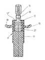
針支持体31がこの典型的な実施態様において頸部3の小さな延長部3′に挿入され、図3に示されるように注射針32を担持する。注射針は頸部3からさらに針支持体31の端部を越えて延びる。保護体33がこの露出した延長端部に取付けられ、頭部5に挿入され、その通路34の中に注射針32を受け入れる。頭部5が折り取り蓋の破壊点又は線に沿って小さな延長部3′から分離された時、保護体33は頭部5に固く連結された状態を維持し、小さな延長部3′に固く連結された針支持体31から上昇される。
【0021】
容器1はカップ形状のブッシュ7に挿入されることなく販売可能な状態にあり、又はこの第1の実施態様では注射されるべき薬物の調製である液体の充填の前にカップ形状のブッシュ7に挿入される。ブッシュの底7′には頭部5と頸部3の通過のための中央開口が設けられる。プラスチックの射出又は噴射部分として構成された本来は静止したピストン8が本来は静止しているブッシュ7の中に受け入れられる。ブッシュ7もまたプラスチックの射出又は噴射部分として形成される。ピストン8がブッシュ7の中に長手方向に摺動自在に案内され、第1の実施態様では容器本体2の軸方向の長さに等しい軸方向の長さを有している。
【0022】
第1の実施態様のブッシュ7は透明な材料で形成されている。ブッシュの外面には軸方向に延びる目盛り10が設けられる。この目盛りは量的に調整された分配量の最低量に対応して細分される。本体2の底に係合するピストン8の端部の周縁はこの目盛り構造と共働する。
【0023】
容器1に収容された材料を取出す前に、頭部5は把持部材6を頸部3に対して回転し又は傾斜させることにより折り取り個所に沿って頸部3の小さな延長部3′から分離される。この時使い捨て注射針は使用のため用意される。注射針32の導入に続いて、ピストン8は分配される容量に対応する軸方向の距離だけブッシュ7に押込まれる。容量の変化と分配された量はピストン8の縁の位置に関連してブッシュ7の目盛り上で読取ることができる。
【0024】
ピストン8は、頸部3を人差し指と中指との間に置きそれにより親指がブッシュ7の外側に延びるピストン8の頂端に当接できるようにすることにより片手を用いるだけで、ブッシュ7に手で押込むことができる。容器1は、本体2の底が頸部3の中への通路と係合した時図2に示されるように頸部3に見られる残りの容量を除き、完全に空にされる。
【0025】
目盛りに加え又はこの目盛りの代わりに、ブッシュ7又はピストン8には一連の環状の凹所を設けることができる。他の部分に形成された環状の突縁を各凹所に強制ロック式に嵌めることができる。任意の2つの続く溝の間の容量に対応する材料の量的に調整された容量がしたがって分配される。第1の実施態様においては、ブッシュ7の内側表面には軸方向に相互に近接して配された環状溝10が設けられている。ピストン8の環状突縁がこの溝10の中に捕えられる。
【0026】
図4に示される容器の第2の実施態様はベローズの構造の本体12を具備している。このような本体は同様に吹込み成形方法により製造することができる。プラスチックの頸部13が直接本体12に形成されそして本体12にその長手方向で連結されている。頸部13は図1から3の第1の実施態様における頸部3より著しく短くし頸部13に残っている残量をできるだけ小さな量に減少させるようにする。くびれた折り取り点又は線の上方に、頭部15が頸部13に直接形成される。容器1の製造、材料の充填及び密封は無菌条件のもとで吹込み成形方法により第1の実施態様のように行われる。さらに、この場合のように、一部材又は多数部材の挿入本体が頸部13又は頸部の小さな延長部に挿入される。この挿入の部分は頭部15に見ることができる。
【0027】
本体12はカップ形状のブッシュ17の中に配置される。ブッシュ底17′は頸部13のための中央通路開口を有している。ブッシュ7の内径と等しいブッシュ17の内径は、本体の長手方向の減少の間直径が拡大する前の本体12又は2の外径よりは大きく少なくとも同じ大きさである。プラスチック射出又は噴射部品として形成されたピストン18は、これもまたプラスチック射出又は噴射部品として形成されたブッシュ17の中に長手方向に摺動自在に案内される。この第2の実施態様において、十分に大きな接触面はブッシュ17の底17′上に置かれる2つの指にとっては存在しない。したがって、2つの直径方向に対向し外側に向って延びるアーム19が直接ブッシュ17の外側に形成される。2つの指をアーム19の上に置くことができ、一方ピストン18は親指でブッシュ17の中に制御されたやり方で押込まれ本体12がその長さに対応して減少されるにしたがって容器に収容されていた材料の量的に調整された分配が行われる。
【0028】
第1の実施態様におけるように、第2の実施態様は図4に見えない表示器を有しブッシュの中のピストンの動きの経路を表示する。この表示器は目盛りを有している。目盛りはピストン18又はブッシュ17上に設けることができる。他の部分にある印付け構造が目盛りと共働する。しかし、目盛りに代えて又は目盛りに加えて、検査要素をブッシュ17とピストン18に設け、例えばピストン18上に直接形成された肩状突出部がロックされた状態に抑止又は係合できるようなブッシュ17の内面の一連の環状溝20を設けることができる。
【0029】
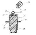
図5から7に示される第3の実施態様は第2の実施態様とは、より小さな容量でありそのため容器の本体22の軸方向の長さがより短かい点と、他の把持部材として追加の半径方向に突出するフランジ29がブッシュ27の外側に直接形成されている点とで、相違している。頸部23、頭部25、及びその把持部材26は第2の実施態様におけるように正確に形成されている。他のそれぞれの特徴部分に対し他の実施態様の記載が参照される。第3の実施態様は使い捨ての針又は噴射装置として形成することができる。
【0030】
本体22に収容されている材料の量的に調整された分配の前に、頭部25は頸部23から折り取り個所又は線に沿って分離される。ピストン28が表示器の助けをかりて調整されそしてブッシュ27の中に押込まれる。本体22の軸方向の長さはそれに応じて減少される。表示器はブッシュ27の内面に相互に近接して配置された環状溝30とピストン28上の環状突縁とを有している。本体22の底に係合するその端部のピストン28の軸方向の延長部28′は、本体22の完全な押圧により、図7に示されるように特に延長部28′が頸部23の中にも若干突入するため、材料の極めて小さな残量が頸部23の中に保持され又は残るにすぎないことを保証する。この第3の実施態様では、本体22が完全に空になった時、ピストン28はなおブッシュ27の開放端部を若干越えて延びる。特に図7に示されるように、ピストン28は減少した直径の外側部分とブッシュ27の内壁に係合する比較的大きな直径の部分とを有している。このピストン構造はピストン28をブッシュ27に推進させるのに対向する摩擦付勢力をもたらすが、この力は比較的小さい。
【0031】
ブッシュ27とピストン28の寸法は、図8に示されるようにブッシュ27がまた本体部分22より著しく長い本体部分32を有する容器を保持することができるように決められる。ブッシュ27とピストン28はプラスチック射出又は噴射部分であり、上記の他の実施態様におけるようにピストンの調整された推進の度合がはっきり見えるようにする表示器が設けられている。挿入本体が挿入されそしてこの第4の実施態様では使い捨て針として用いられる注射針を担持する。
【0032】
様々な実施態様が本発明を例示するために選択されたが、当業者にとって、種々の変更と変形が特許請求の範囲に記載された発明の範囲を逸脱することなく行われることが理解されるであろう。
【図面の簡単な説明】
【図1】本発明の第1の実施態様による容器の使用前の一部切断側面図である。
【図2】完全に空となった図1の容器の一部切断側面図である。
【図3】頭部を除いた図1と2の容器の頭部と頸部の切断部分側面図である。
【図4】本発明の第2の実施態様の容器の使用前の部分切断側面図である。
【図5】本発明の第3の実施態様の容器の使用前の切断側面図である。
【図6】図5の容器の開放した後でその内容物を分配する前の切断側面図である。
【図7】図5容器の完全に空となったときの切断側面図である。
【図8】本発明の第4の実施態様の容器の使用前の部分切断側面図である。
【符号の説明】
1…容器
2…容器本体
3…頸部
3′…小延長部
4…リブ
5…頭部
6…把持部材
7…ブッシュ
7′…ブッシュの底
8…ピストン
10…目盛り(環状溝)
12…本体
13…頸部
15…頭部
17…ブッシュ
18…ピストン
19…アーム
20…環状溝
31…針支持体
32…注射針
33…保護体[0001]
BACKGROUND OF THE INVENTION
The present invention relates to an apparatus for dispensing a flowable material out of a deformable plastic container. The container has a collapsible body that collapses longitudinally and a small diameter neck in the form of a shoulder-like projection connected to one end of the collapsible body. This flowable material is dispensed through the neck in an amount corresponding to a longitudinal decrease in the volume of the body.
[0002]
In known containers of this type, the container can be folded across its length or along the longitudinal axis. The distribution of the material contained in the container is only very accurately adjusted quantitatively.
[0003]
[Problems to be solved by the invention]
It is an object of the present invention to provide a container that facilitates a quantitatively adjusted or dispensed distribution of material contained within the container.
[0004]
[Means for Solving the Problems]
The above objective is basically achieved by a container for the dispensing of flowable material, which container comprises a longitudinally compressible deformable plastic body and a first transverse diameter. And a shoulder-like protrusion. The body defines an internal volume and has an axial length. A neck is coupled to one axial end of the body and has a second lateral diameter that is less than the first lateral diameter. This neck has a small protrusion through which the flowable material is distributed. A cup-shaped bush has a bush bottom and a bottom passage opening for receiving the neck. The bush bottom engages with the shoulder-like protrusion of the main body. A piston is slidably mounted on the bush and can move to each position in the bush relative to the bush bottom. An indicator displays the movement of the piston in the bush. The movement of the piston in the bush toward the bottom of the bush reduces the volume of the body by reducing the axial length and regulates the quantitative release of flowable material through the neck.
[0005]
The user is not required to crush the container directly with a finger since a bushing is provided for this purpose. The bush receives and holds the container body and the piston. The indicator displays the sliding path of the slidable piston. The container body can be reduced in length to any degree required to dispense the desired amount of material contained in the container without difficulty.
[0006]
Each container body may be commercially available in a commercially available state attached to its associated bushing. However, the container body can also be introduced into the bush only just before the container is dispensed. The piston combined with this bush can then be used for a plurality of similar containers.
[0007]
The container can be manufactured by blow molding or suction molding methods, and can be filled in a mold and closed in a seal. The device of the present invention is thereby suitable for those materials that must be filled under aseptic conditions and stored until use.
[0008]
An insertion body of one or more parts can be inserted into the neck and / or head. Preferably, this insertion takes place before the last formation and shaping of the part of the container that receives the insertion body, in other words while the container is still in the production mold. The inserted body can be a stopper, for example. An insertion body that supports a needle that is not free or exposed until the head is separated is a particularly advantageous structure. The container of the present invention can also be used as a disposable needle or spray device. Such disposable needles or injection devices are particularly low cost.
[0009]
In a preferred embodiment, both the bush and the piston are made of plastic. Thus, the bush and piston can be manufactured in a simple and inexpensive manner.
[0010]
The display device can be calibrated and can have a marking structure that cooperates with the scale. When the container is transparent, for example, a scale can be applied on the container and a marking can be applied on the piston. Also, the end of the piston located inside the bush can form a mark. In addition to this, a scale can be applied to the piston, the bush can be marked, or its exposed end can be used as a marking device. However, the indicator can also include a cooperating test element. This inspection element allows the piston to be restrained by engagement at a predetermined position inside the bush. These positions are given along the piston propulsion path, preferably equidistant from each other. These inspection elements are preferably formed directly on the bushing or piston. For example, the piston can be provided with a protruding shoulder, and the bush can be provided with a recess, or vice versa. These recesses can be in the form of grooves, thereby eliminating positioning problems.
[0011]
The container neck should be as short as possible to ensure that only a very small amount of content remains in the container when it is fully crushed. Furthermore, the piston can have an axially protruding portion of material at its end that engages the body. This piece of material pushes the bottom of the container into the interior of the container.
[0012]
A gripper can be provided to allow comfortable operation of the device of the present invention. The gripper can project outward from the outside of the bush and forms a contact surface for the index and middle fingers. Only the thumb is required for the operation of the piston. This gripping structure can be composed of a flange formed on the bush or two diametrically opposed arms arranged on the bush.
[0013]
Towards the end of the dispensing phase, the device is still comfortably controlled so that the length of the piston is at least equal to the length of the bush, according to an advantageous embodiment.
[0014]
Different shapes and formats are possible for the container. For example, an outer diameter that is large compared to the length of the axial direction may be selected so that the walls forming the container cover are not particularly necessary to resist deformation. Advantageously, the container can also be in the form of a bellows.
[0015]
Other objects, advantages and salient features of the present invention will become apparent from the following detailed description, which, taken in conjunction with the accompanying drawings, discloses preferred embodiments of the present invention.
[0016]
DETAILED DESCRIPTION OF THE INVENTION
Referring to the drawings that form part of the disclosure of the present invention, the first embodiment of the present invention shown enlarged in FIGS. 1 and 2 shows a
[0017]
Between the reduced
[0018]
The shoulder-like projecting surface forming the transition portion or the connecting portion from the outer surface of the main body 2 to the
[0019]
[0020]
A
[0021]
The
[0022]
The
[0023]
Before removing the material contained in the
[0024]
The piston 8 is placed on the
[0025]
In addition to or instead of the scale, the
[0026]
The second embodiment of the container shown in FIG. 4 comprises a
[0027]
The
[0028]
As in the first embodiment, the second embodiment has an indicator not visible in FIG. 4 and displays the path of movement of the piston in the bush. This indicator has a scale. The scale can be provided on the
[0029]
The third embodiment shown in FIGS. 5 to 7 is different from the second embodiment in that it has a smaller capacity and therefore has a shorter axial length of the
[0030]
Prior to the quantitative adjustment of the material contained in the
[0031]
The dimensions of the
[0032]
While various embodiments have been selected to illustrate the present invention, it will be understood by those skilled in the art that various modifications and variations can be made without departing from the scope of the invention as set forth in the claims. Will.
[Brief description of the drawings]
FIG. 1 is a partially cut side view of a container according to a first embodiment of the present invention before use.
FIG. 2 is a partially cutaway side view of the container of FIG. 1 completely emptied.
FIG. 3 is a cut-away side view of the head and neck of the container of FIGS. 1 and 2 with the head removed.
FIG. 4 is a partially cut side view of the container according to the second embodiment of the present invention before use.
FIG. 5 is a cut-away side view of the container according to the third embodiment of the present invention before use.
6 is a cut-away side view of the container of FIG. 5 after opening and before dispensing its contents.
FIG. 7 is a cut-away side view when the container is completely emptied.
FIG. 8 is a partially cutaway side view of the container of the fourth embodiment of the present invention before use.
[Explanation of symbols]
DESCRIPTION OF
DESCRIPTION OF
Claims (12)
Translated fromJapanese長手方向に圧縮可能で第1の横方向の直径と肩状突出部とを有し、内部の容積を区画形成し軸方向の長さを有している、変形可能なプラスチックの本体と、
前記本体の一方の軸方向端部に連結され、前記第1の横方向の直径より小さい第2の横方向の直径と流動性材料が分配されて通過する小さな突出部とを有している頸部と、
ブッシュの底と前記頸部を受け入れる前記底の通過開口とを有し、前記底が前記本体の前記肩状突出部と係合している、カップ形状のブッシュと、
前記ブッシュの中に摺動自在に取付けられ前記ブッシュの底に対する前記ブッシュの中の各位置に移動可能なピストンと、
前記ピストンの前記ブッシュの中の動きを表示する表示器
とを具備し、
前記ブッシュの底に向う前記ブッシュの中の前記ピストンの動きが、前記軸方向の長さを減少することにより前記本体の前記容積を減少し前記頸部を通過する流動性材料の放出量を調整するようにしていて、
前記頸部が挿入本体を含んでおり、
前記挿入本体が使い捨ての針として用いる注射針を具備している、
流動性材料を分配する容器。A container for dispensing flowable material,
A deformable plastic body that is longitudinally compressible and has a first lateral diameter and a shoulder-like projection, defining an internal volume and having an axial length;
A neck connected to one axial end of the body and having a second lateral diameter smaller than the first lateral diameter and a small protrusion through which the flowable material is distributed and passed. And
A cup-shaped bush having a bottom of the bush and a passage opening in the bottom for receiving the neck, the bottom engaging the shoulder-like protrusion of the body;
A piston slidably mounted in the bush and movable to each position in the bush relative to the bottom of the bush;
An indicator for indicating movement of the piston in the bush;
The movement of the piston in the bush towards the bottom of the bush reduces the volume of the body by reducing the axial length and regulates the amount of fluid material released through the neck. We are trying tobe,
The neck includes an insertion body;
The insertion body has an injection needle used as a disposable needle,
A container that dispenses flowable material.
Applications Claiming Priority (2)
| Application Number | Priority Date | Filing Date | Title |
|---|---|---|---|
| DE19522451:5 | 1995-06-21 | ||
| DE19522451ADE19522451C2 (en) | 1995-06-21 | 1995-06-21 | Device for dispensing a flowable substance from a container |
Publications (2)
| Publication Number | Publication Date |
|---|---|
| JPH0999959A JPH0999959A (en) | 1997-04-15 |
| JP3662672B2true JP3662672B2 (en) | 2005-06-22 |
Family
ID=7764842
Family Applications (1)
| Application Number | Title | Priority Date | Filing Date |
|---|---|---|---|
| JP15686796AExpired - LifetimeJP3662672B2 (en) | 1995-06-21 | 1996-06-18 | Container for dispensing flowable material |
Country Status (12)
| Country | Link |
|---|---|
| US (1) | US5836922A (en) |
| EP (1) | EP0749759B1 (en) |
| JP (1) | JP3662672B2 (en) |
| AU (1) | AU705767B2 (en) |
| CA (1) | CA2178027C (en) |
| DE (2) | DE19522451C2 (en) |
| DK (1) | DK0749759T3 (en) |
| ES (1) | ES2171575T3 (en) |
| IN (1) | IN190912B (en) |
| MX (1) | MX9602436A (en) |
| NO (1) | NO311883B1 (en) |
| TW (1) | TW359657B (en) |
Families Citing this family (44)
| Publication number | Priority date | Publication date | Assignee | Title |
|---|---|---|---|---|
| US6402718B1 (en)* | 1992-08-17 | 2002-06-11 | Medrad, Inc. | Front-loading medical injector and syringe for use therewith |
| DE19701494A1 (en)* | 1997-01-17 | 1998-07-23 | Boehringer Mannheim Gmbh | Transdermal injection system |
| JP3001460B2 (en)* | 1997-05-21 | 2000-01-24 | 株式会社エヌイーシー情報システムズ | Document classification device |
| US6077252A (en)* | 1997-09-17 | 2000-06-20 | Siegel; Robert | Single or multiple dose syringe |
| US6135771A (en)* | 1997-12-02 | 2000-10-24 | Centrix, Inc. | Dental cartridge having an attachable delivery portion |
| US6276568B1 (en)* | 1998-08-21 | 2001-08-21 | Pharmacia & Upjohn Company | Spray bottle grip |
| USD421120S (en)* | 1998-08-21 | 2000-02-22 | Pharmacia & Upjohn Company | Spray bottle grip |
| USD428141S (en)* | 1999-08-04 | 2000-07-11 | Pharmacia & Upjohn Company | Spray bottle grip |
| JP2001104324A (en)* | 1999-10-06 | 2001-04-17 | Ngk Spark Plug Co Ltd | Medicine extruding auxiliary device, and medicine extruding method using the same |
| US6247617B1 (en) | 1999-12-13 | 2001-06-19 | Richard Allen Clyde | Single use container for dispensing separately housed sterile compositions |
| US6644309B2 (en)* | 2001-01-12 | 2003-11-11 | Becton, Dickinson And Company | Medicament respiratory delivery device and method |
| DE10110742A1 (en)* | 2001-02-28 | 2002-09-05 | Pfeiffer Erich Gmbh & Co Kg | Media Donor |
| KR100789120B1 (en)* | 2001-07-17 | 2007-12-28 | 베른트 한센 | Material distribution device |
| US6805842B1 (en)* | 2001-10-12 | 2004-10-19 | Mds Sciex | Repuncturable self-sealing sample container with internal collapsible bag |
| US8672892B2 (en)* | 2003-04-22 | 2014-03-18 | Smiths Medical Asd, Inc. | Tamper evident vacuum tube holder assembly and needle hub assembly therefor |
| DE10360185A1 (en)* | 2003-12-20 | 2005-08-04 | Max Wyssmann | Device for targeted, controllable delivery or for sucking a liquid or a viscous mass |
| EP1847242B1 (en)* | 2005-02-08 | 2015-06-17 | Toyo Seikan Kaisha, Ltd. | Sterile package, process for producing the same, and production apparatus |
| US7762427B2 (en)* | 2005-06-10 | 2010-07-27 | Kranson Industries, Inc. | Pump dispensing mechanism |
| US8684968B2 (en)* | 2006-12-29 | 2014-04-01 | Aktivpak, Inc. | Hypodermic drug delivery reservoir and apparatus |
| WO2009086463A1 (en)* | 2007-12-28 | 2009-07-09 | Aktivpak, Inc. | Dispenser and therapeutic package suitable for administering a therapeutic substance to a subject |
| US9498570B2 (en) | 2010-10-25 | 2016-11-22 | Bayer Healthcare Llc | Bladder syringe fluid delivery system |
| US10046106B2 (en) | 2010-10-25 | 2018-08-14 | Bayer Healthcare Llc | Bladder syringe fluid delivery system |
| US20120279995A1 (en)* | 2011-05-06 | 2012-11-08 | Specialty Lubricants Corporation | Accordion bottle |
| US9180252B2 (en) | 2012-04-20 | 2015-11-10 | Bayer Medical Care Inc. | Bellows syringe fluid delivery system |
| US20130310760A1 (en)* | 2012-05-21 | 2013-11-21 | Becton, Dickinson And Company | Stopper Having a Scale Line Formed Thereon |
| EP2786774A1 (en)* | 2013-04-04 | 2014-10-08 | Flamina Holding AG | Disposable syringe |
| KR101423590B1 (en)* | 2013-12-31 | 2014-07-25 | 주식회사 라온 | Micro needle stamp |
| ES2873963T3 (en) | 2014-04-25 | 2021-11-04 | Bayer Healthcare Llc | Rolling Diaphragm Syringe |
| US10933190B2 (en) | 2015-04-24 | 2021-03-02 | Bayer Healthcare Llc | Syringe with rolling diaphragm |
| AR109649A1 (en) | 2016-09-16 | 2019-01-09 | Bayer Healthcare Llc | PRESSURE SHIRT WITH SYRINGE RETAINING ELEMENT |
| CN109843355B (en) | 2016-10-17 | 2022-03-25 | 拜耳医药保健有限公司 | Fluid Syringe with Syringe Engagement Mechanism |
| CA3040484A1 (en) | 2016-10-17 | 2018-04-26 | Bayer Healthcare Llc | Fluid injector with syringe engagement mechanism |
| WO2019055497A1 (en) | 2017-09-13 | 2019-03-21 | Bayer Healthcare Llc | Sliding syringe cap for separate filling and delivery |
| AU2019340438A1 (en) | 2018-09-11 | 2021-03-04 | Bayer Healthcare Llc | Syringe retention feature for fluid injector system |
| US11918775B2 (en) | 2019-09-10 | 2024-03-05 | Bayer Healthcare Llc | Pressure jackets and syringe retention features for angiography fluid injectors |
| EP3808394A1 (en)* | 2019-10-15 | 2021-04-21 | Chung-Sing Lin | Syringe device |
| CR20220394A (en) | 2020-02-21 | 2023-01-23 | Bayer Healthcare Llc | Fluid path connectors for medical fluid delivery |
| PT4110452T (en) | 2020-02-28 | 2025-01-14 | Bayer Healthcare Llc | FLUID MIXING SET |
| WO2021188460A1 (en) | 2020-03-16 | 2021-09-23 | Bayer Healthcare Llc | Stopcock apparatus for angiography injector fluid paths |
| CN115697435A (en) | 2020-06-18 | 2023-02-03 | 拜耳医药保健有限责任公司 | Inline Bubble Suspension Device for the Fluid Path of Angiography Injectors |
| RS66861B1 (en) | 2020-08-11 | 2025-06-30 | Bayer Healthcare Llc | Features for angiography syringe |
| CN116547022A (en) | 2020-12-01 | 2023-08-04 | 拜耳医药保健有限责任公司 | Cassette for holding fluid path components of a fluid injector system |
| WO2022265695A1 (en) | 2021-06-17 | 2022-12-22 | Bayer Healthcare Llc | System and method for detecting fluid type in tubing for fluid injector apparatus |
| US20250100777A1 (en)* | 2023-09-25 | 2025-03-27 | Becton, Dickinson And Company | Fluid Dispensing Device |
Family Cites Families (33)
| Publication number | Priority date | Publication date | Assignee | Title |
|---|---|---|---|---|
| DE7313852U (en)* | 1973-07-26 | Fribad Gmbh | Container for impasto masses | |
| US1863785A (en)* | 1930-03-08 | 1932-06-21 | Fairleigh S Dickinson | Syringe |
| US2514575A (en)* | 1945-02-17 | 1950-07-11 | Howard T Hein | Introversion syringe |
| US2505411A (en)* | 1949-05-11 | 1950-04-25 | East Rutherford Syringes Inc | Glass syringe having lettering embedded flush therein |
| US2595493A (en)* | 1949-09-09 | 1952-05-06 | Ollie F Slaby | Liquid extracting apparatus |
| US2685878A (en)* | 1953-04-24 | 1954-08-10 | Sr David Walter Seifert | Capsule type dental syringe |
| NL92087C (en)* | 1954-09-03 | |||
| US2950717A (en)* | 1955-03-21 | 1960-08-30 | R K Price Associates Inc | Ampules |
| GB1051142A (en)* | 1962-09-11 | 1900-01-01 | ||
| US3161194A (en)* | 1963-02-04 | 1964-12-15 | Samuel L Chapman | Hypodermic syringe |
| US3190619A (en)* | 1963-05-27 | 1965-06-22 | Union Carbide Corp | Fluid mixing container assembly |
| GB1217152A (en)* | 1967-03-14 | 1970-12-31 | Arthur Bane | Improvements in appliances for storing and dispensing fluids, such as hypodermic syringes and eye drop dispensers |
| FR1570600A (en)* | 1968-03-28 | 1969-06-13 | ||
| FR2174705A1 (en)* | 1972-03-08 | 1973-10-19 | Savary Andre | Injection ampoule-syringe - for throwing away after use |
| US3938514A (en)* | 1974-07-18 | 1976-02-17 | Boucher Lionel J | Bladder wash method and apparatus |
| US3998223A (en)* | 1975-10-24 | 1976-12-21 | The United States Of America As Represented By The Secretary Of The Navy | Syringe apparatus |
| DE7737934U1 (en)* | 1977-12-13 | 1981-01-22 | Fischer Artur Dr H C | Container with removable cap for packing and spraying fabrics |
| DE2851532C2 (en)* | 1978-11-29 | 1981-02-19 | Boehringer Mannheim Gmbh, 6800 Mannheim | Pipette with elastic bellows |
| JPS5731870A (en)* | 1980-08-05 | 1982-02-20 | Korupo Kk | Injector |
| WO1983000882A1 (en)* | 1981-08-29 | 1983-03-17 | Toshiro Ninomiya | Injection ampule and injection ampule mounting unit |
| DE3344345A1 (en)* | 1983-12-08 | 1985-06-13 | Henkel KGaA, 4000 Düsseldorf | Fluid material disposable package |
| FR2633187A1 (en)* | 1988-06-23 | 1989-12-29 | Gafner Paul Felix | SKIN APPLICATOR DEVICE OF A DRUG SOLUTION FOR DERMATOLOGICAL TREATMENT |
| DE3823428A1 (en)* | 1988-07-11 | 1990-01-18 | Hansen Bernd | PLASTIC AMPOULE |
| US4966312A (en)* | 1988-12-06 | 1990-10-30 | Waring Donald A | Disposable oral liquid measure dispenser |
| US5356016A (en)* | 1991-11-20 | 1994-10-18 | Wiedemann Warren T | Baby nursing bottle |
| US5242422A (en)* | 1991-11-29 | 1993-09-07 | Professional Medical Products, Inc. | One piece molded syringe with tethered cap |
| DE4234383A1 (en)* | 1992-10-06 | 1994-04-07 | Kaeufer Helmut Prof Dr | Reusable medical syringe having modular design - allows simple exchange of inner module comprising liq.-contacting elements. |
| US5356037A (en)* | 1993-06-21 | 1994-10-18 | Pakmax, Inc. | Lift and drop ratchet stick dispenser |
| US5337925A (en)* | 1993-07-26 | 1994-08-16 | Ispg, Inc. | Injection device for injecting a fluid into food |
| US5538506A (en)* | 1993-11-03 | 1996-07-23 | Farris; Barry | Prefilled fluid syringe |
| ES2160154T3 (en)* | 1993-12-22 | 2001-11-01 | Merck & Co Inc | PACKAGING AND DEVICE FOR OPHTHALMIC ADMINISTRATION. |
| DE4419235C2 (en)* | 1994-06-01 | 1999-03-11 | Thomas Braeger | Hypodermic syringe with a receptacle |
| US5609580A (en)* | 1994-09-16 | 1997-03-11 | Vital Signs, Inc. | Injection holder for a plungerless syringe and combination plungerless syringe and injection holder |
- 1995
- 1995-06-21DEDE19522451Apatent/DE19522451C2/ennot_activeExpired - Fee Related
- 1996
- 1996-05-22DKDK96108132Tpatent/DK0749759T3/enactive
- 1996-05-22DEDE59608662Tpatent/DE59608662D1/ennot_activeExpired - Lifetime
- 1996-05-22ESES96108132Tpatent/ES2171575T3/ennot_activeExpired - Lifetime
- 1996-05-22EPEP96108132Apatent/EP0749759B1/ennot_activeExpired - Lifetime
- 1996-06-03CACA002178027Apatent/CA2178027C/ennot_activeExpired - Lifetime
- 1996-06-03ININ1017CA1996patent/IN190912B/enunknown
- 1996-06-05TWTW085106710Apatent/TW359657B/ennot_activeIP Right Cessation
- 1996-06-14AUAU55993/96Apatent/AU705767B2/ennot_activeExpired
- 1996-06-18JPJP15686796Apatent/JP3662672B2/ennot_activeExpired - Lifetime
- 1996-06-20NONO19962617Apatent/NO311883B1/ennot_activeIP Right Cessation
- 1996-06-21MXMX9602436Apatent/MX9602436A/enunknown
- 1996-06-21USUS08/670,187patent/US5836922A/ennot_activeExpired - Lifetime
Also Published As
| Publication number | Publication date |
|---|---|
| EP0749759A1 (en) | 1996-12-27 |
| US5836922A (en) | 1998-11-17 |
| AU5599396A (en) | 1997-01-09 |
| CA2178027A1 (en) | 1996-12-22 |
| DK0749759T3 (en) | 2002-05-13 |
| NO962617D0 (en) | 1996-06-20 |
| EP0749759B1 (en) | 2002-01-30 |
| MX9602436A (en) | 1997-02-28 |
| TW359657B (en) | 1999-06-01 |
| CA2178027C (en) | 2005-08-30 |
| IN190912B (en) | 2003-08-30 |
| JPH0999959A (en) | 1997-04-15 |
| AU705767B2 (en) | 1999-06-03 |
| DE59608662D1 (en) | 2002-03-14 |
| ES2171575T3 (en) | 2002-09-16 |
| NO311883B1 (en) | 2002-02-11 |
| DE19522451C2 (en) | 1997-11-06 |
| DE19522451A1 (en) | 1997-01-02 |
| NO962617L (en) | 1996-12-23 |
Similar Documents
| Publication | Publication Date | Title |
|---|---|---|
| JP3662672B2 (en) | Container for dispensing flowable material | |
| AU645631B2 (en) | Sleeved dispensing vial | |
| US5217433A (en) | Medication container for mixing two components | |
| US6343717B1 (en) | Pre-filled disposable pipettes | |
| US3993223A (en) | Dispensing container | |
| US4234103A (en) | Diagnostic reagent dispensing bottle | |
| EP3125852B1 (en) | Controlled release container | |
| CA2474907C (en) | Moulding method, in particular a blowing or vacuum moulding method for production of a dispensing container filled with a medium for dispensing | |
| EP2089282B1 (en) | Metered drop bottle for dispensing microliter amounts of a liquid in the form of a drop | |
| US2873886A (en) | Dispenser | |
| LV12925B (en) | Ophthalmic package and delivery device | |
| US3985146A (en) | Disposable shaving kit | |
| EP3774262B1 (en) | A method of forming a flip-top cap and a flip-top cap | |
| WO1983001241A1 (en) | Bottle closure and method of making same | |
| EP4440947A1 (en) | Blow molded transfer tube and methods of making the same | |
| US3114369A (en) | Disposable ampul | |
| CA2003253A1 (en) | Device for emptying bag-in-box packs | |
| EP3498126A1 (en) | Ampoule for storing cosmetic liquid | |
| US4413754A (en) | Dispenser of small quantities of liquids | |
| US6929152B2 (en) | Assembly for the packaging and application of a fluid product | |
| JPS62176451A (en) | Package for mixing injection | |
| JP2002085153A (en) | Feeding vessel for stick cosmetics | |
| EP0014283A1 (en) | Container for a fluid and a closure member | |
| WO2024012869A1 (en) | Reusable closures | |
| EP1529743A2 (en) | Container-batcher |
Legal Events
| Date | Code | Title | Description |
|---|---|---|---|
| A977 | Report on retrieval | Free format text:JAPANESE INTERMEDIATE CODE: A971007 Effective date:20040722 | |
| A131 | Notification of reasons for refusal | Free format text:JAPANESE INTERMEDIATE CODE: A131 Effective date:20040727 | |
| A601 | Written request for extension of time | Free format text:JAPANESE INTERMEDIATE CODE: A601 Effective date:20041026 | |
| A602 | Written permission of extension of time | Free format text:JAPANESE INTERMEDIATE CODE: A602 Effective date:20041029 | |
| A521 | Request for written amendment filed | Free format text:JAPANESE INTERMEDIATE CODE: A523 Effective date:20050126 | |
| TRDD | Decision of grant or rejection written | ||
| A01 | Written decision to grant a patent or to grant a registration (utility model) | Free format text:JAPANESE INTERMEDIATE CODE: A01 Effective date:20050222 | |
| A61 | First payment of annual fees (during grant procedure) | Free format text:JAPANESE INTERMEDIATE CODE: A61 Effective date:20050324 | |
| R150 | Certificate of patent or registration of utility model | Free format text:JAPANESE INTERMEDIATE CODE: R150 | |
| FPAY | Renewal fee payment (event date is renewal date of database) | Free format text:PAYMENT UNTIL: 20090401 Year of fee payment:4 | |
| FPAY | Renewal fee payment (event date is renewal date of database) | Free format text:PAYMENT UNTIL: 20100401 Year of fee payment:5 | |
| FPAY | Renewal fee payment (event date is renewal date of database) | Free format text:PAYMENT UNTIL: 20110401 Year of fee payment:6 | |
| FPAY | Renewal fee payment (event date is renewal date of database) | Free format text:PAYMENT UNTIL: 20120401 Year of fee payment:7 | |
| FPAY | Renewal fee payment (event date is renewal date of database) | Free format text:PAYMENT UNTIL: 20130401 Year of fee payment:8 | |
| FPAY | Renewal fee payment (event date is renewal date of database) | Free format text:PAYMENT UNTIL: 20140401 Year of fee payment:9 | |
| R250 | Receipt of annual fees | Free format text:JAPANESE INTERMEDIATE CODE: R250 | |
| R250 | Receipt of annual fees | Free format text:JAPANESE INTERMEDIATE CODE: R250 | |
| R250 | Receipt of annual fees | Free format text:JAPANESE INTERMEDIATE CODE: R250 | |
| EXPY | Cancellation because of completion of term |