JP3662378B2 - Network repeater - Google Patents
Network repeaterDownload PDFInfo
- Publication number
- JP3662378B2 JP3662378B2JP33715396AJP33715396AJP3662378B2JP 3662378 B2JP3662378 B2JP 3662378B2JP 33715396 AJP33715396 AJP 33715396AJP 33715396 AJP33715396 AJP 33715396AJP 3662378 B2JP3662378 B2JP 3662378B2
- Authority
- JP
- Japan
- Prior art keywords
- vlan
- terminal
- unit group
- data packet
- vlanid
- Prior art date
- Legal status (The legal status is an assumption and is not a legal conclusion. Google has not performed a legal analysis and makes no representation as to the accuracy of the status listed.)
- Expired - Fee Related
Links
- 230000005540biological transmissionEffects0.000claimsdescription24
- 238000010586diagramMethods0.000description16
- 238000000034methodMethods0.000description9
- 101100048435Caenorhabditis elegans unc-18 geneProteins0.000description2
- 239000000284extractSubstances0.000description1
- 230000006870functionEffects0.000description1
Images


Classifications
- H—ELECTRICITY
- H04—ELECTRIC COMMUNICATION TECHNIQUE
- H04L—TRANSMISSION OF DIGITAL INFORMATION, e.g. TELEGRAPHIC COMMUNICATION
- H04L12/00—Data switching networks
- H04L12/28—Data switching networks characterised by path configuration, e.g. LAN [Local Area Networks] or WAN [Wide Area Networks]
- H04L12/46—Interconnection of networks
- H04L12/4641—Virtual LANs, VLANs, e.g. virtual private networks [VPN]
Landscapes
- Engineering & Computer Science (AREA)
- Computer Security & Cryptography (AREA)
- Computer Networks & Wireless Communication (AREA)
- Signal Processing (AREA)
- Small-Scale Networks (AREA)
Description
Translated fromJapanese【0001】
【発明の属する技術分野】
本発明は、ネットワークシステム中に備えられ、情報の塊としてのデータパケットの送信を中継する、いわゆるルータ等と呼ばれるネットワーク中継器に関する。
【0002】
【従来の技術】
従来より、ネットワークシステム中にそのネットワーク内で送受信されるデータパケットの送信を中継するネットワーク中継器が存在する。
図5は、ネットワークシステムの一例を示す模式図である。
このネットワークシステムは、データパケットの入出力を司る3つのポート(ポート1,ポート2,ポート3)を備えたネットワーク中継器11と、各ポート1,2,3に接続された各LAN(Local Area Network)1,2,3と、それらのLAN1,2,3のいずれかを経由していずれかのポートに接続された多数の端末A〜Jとから構成されている。ここで、これら多数の端末のうち端末A〜Cはポート1、端末D〜Gはポート2、端末H〜Jはポート3に接続されている。
【0003】
ここで端末Aから端末Dに向けてデータパケットを送信する場合、発信元である端末Aから送信されたデータパケットは、LAN1を経由し、ポート1からネットワーク中継器11に入力され、ネットワーク中継器11では、そのデータパケット中の受信先アドレスから受信先の端末Dがポート2に接続された端末であることを知り、ポート2からLAN2にそのデータパケットを出力する。
【0004】
端末Dは、LAN2を経由して送られてきたデータパケット中の受信先アドレスから、自分が受信すべきデータパケットであることを知り、受信する。このようにしてデータパケットの送受信が行なわれる。ところで、近年データ通信の安全性の問題からVLAN(Virtual LAN;バーチャルLAN)なる考え方が採用されてきている。VLANとは、各ポート1,2,3に接続された物理的なLAN1,2,3から離れて通信を行なうことができるグループとして定義された論理的なLANであり、例えば図5に示す例では、破線で囲まれた端末A,B,D,E,FがVLAN1と名づけられた1つのVLANを構成し、一点鎖線で囲まれた端末D,E,H,I,JがVLAN2と名付けられた1つのVLANを構成し、点線で囲まれた端末C,E,F,G,JがVLAN3と名付けられた1つのVLANを構成しているものとする。この例に示すように、1つの端末が複数のVLANに属することも許容されている。
【0005】
図6は、図5に示す端末とVLANとの関係を示す模式図である。ここに示す例では、端末A,BはVLAN1のみに属し1、端末H,IはVLAN2のみに属し、端末C,GはVLAN3のみに属し、端末DはVLAN1とVLAN2に属し、端末JはVLAN2とVLAN3に属し、端末FはVLAN3とVLAN1に属し、端末EはVLAN1とVLAN2とVLAN3に属している。
【0006】
ネットワーク中継器11には、各端末のアドレスと、各端末が属するVLANのVLANIDと、各端末が接続されたポートのポートIDとの対応関係が記録されており、ネットワーク中継器11にデータパケットが入力されると、そのネットワーク中継器では、そのデータパケットの発信元アドレスと受信先アドレスを見て発信元端末と受信先端末が同一のVLANに属しているか否かを知り、同一のVLANに属している場合に、受信先端末が接続されているポートからそのデータパケットが送り出される。
【0007】
【発明が解決しようとする課題】
図7は、ネットワーク中継器における、各端末のアドレスと、各端末が属するVLANのVLANIDと、各端末が接続されたポートのポートIDとの対応関係を示すVLAN制御テーブルの一例を示す図である。
ここでは、各端末のアドレス(MACアドレス)と、各端末が属するVLANを識別するVLANIDと、各端末が接続されたポートを識別するポートIDが単純にテーブル化されている。
【0008】
例えばMACアドレスAの端末(端末A)は、VLAN1に属し、ポート1の先に接続されており、MACアドレスDの端末(端末D)は、VLAN1とVLAN2に属し、ポート2の先に接続されており、MACアドレスEの端末(端末E)は、VLAN1とVLAN2とVLAN3に属し、ポート2の先に接続されている。
【0009】
ここで例えばVLAN2とVLAN3に属する端末Jが発信元となってVLAN1とVLAN3に属する端末Fにデータパケットを送信する場合を考える。これらの端末J,Eは、VLAN3という共通のVLANに属しており、したがってこれらの端末J,Eの間で通信を行なうことができる。
この場合、ネットワーク中継器11では、先ず、入力されてきたデータパケット中の発信元アドレスJから、その端末JがVLAN2に属していることを知り、かつそのデータパケット中の受信先アドレスEからその端末EがVLAN1に属していることを知り、それらVLAN2とVLAN1との比較を行なう。ここでは一致しないため、次に、端末EがVLAN3に属していることを知り、端末FのVLAN2と端末EのVLAN3との比較を行なう。これも一致しないため、端末JがVLAN3に属していることを知り、かつ端末FがVLAN2に属していることを知り、これらVLAN3とVLAN2との比較を行なう。不一致であることから、端末FがVLAN3にも属していることを知り、VLAN3とVLAN3との比較を行ない、今度は一致し、したがって入力されてきたデータパケットを端末Eへ送信してもよいことを知り、その端末Eが接続されているポート2からそのデータパケットを送り出す。このようにして、図7に示すテーブルによって、一応、発信元端末と受信先端末が同一のVLANに属しているか否かを知り、同一のVLANに属している場合に、受信先端末に向けてデータパケットを送り出すことは可能であるが、発信元端末と受信先端末が同一のVLANに属しているか否かを知るために上述したような逐次比較を必要とし、各端末がそれぞれ多数のVLANに属している場合、このような逐次比較により共通のVLANを見つける手法では多大な時間を必要とし、通信速度の低下を招くという問題がある。
【0010】
図8は、各端末のアドレス(MACアドレス)と、各端末が属するVLANとの、もう1つの対応付方法を示す図である。
ここでは、各MACアドレス(各端末)毎に、VLANの最大数n+1の長さのビット配列を備え、ビット0にVLAN1,ビット1にVLAN2,ビット2にVLAN3、というように各ビットに各VLANが割り当てられている。
【0011】
例えば図8(a)には、MACアドレスA(端末A)に対応するn+1ビットのビット配列が示されており、ビット0のみ‘1’、他の全てのビットを‘0’とし、これにより、端末AがVLAN1にのみ属していることが示されている。また同様に、図8(b)には、MACアドレスD(端末D)に対応するn+1ビットのビット配列が示されており、ビット0とビット1が‘1’、他のビットが‘0’であることから、端末DはVLAN1とVLAN2に属していることがわかる。さらに、図8(c)にはMACアドレスE(端末E)に対応するn+1ビットのビット配列が示されており、ビット0〜2が‘1’、他のビットが‘0’であることから、端末EはVLAN1,2,3に属していることがわかる。
【0012】
各端末がどのVLANに属するかをこのようなビット配列の形式で持った場合、発信元端末に対応するビット配列と受信側端末に対応するビット配列について、各対応するビット毎にAND演算を行ない、それら各対応するビット毎のAND演算結果全体についてOR演算を行なうと、そのOR演算結果が論理‘1’のときは、発信元端末と受信側端末が同一のVLANに属し、そのOR演算結果が論理‘0’のときは同一のVLANには属していないことが判明する。すなわち、図8に示すようなビット配列の形式の場合、逐次比較は不要であって、単純な演算により同一のVLANに属しているか否かを知ることができ、高速通信が可能である。
【0013】
しかしながら、図8に示す形式の場合、各端末毎にビット配列を必要とするため多大なメモリ容量を必要とし、また、VLANの最大数と同じ長さのビット配列を必要とするためVLANの最大数を小さく見積ると拡張性に乏しくVLANの最大数を大きく見積もるとさらに膨大な容量のメモリを必要とするという問題がある。
【0014】
本発明は、上記事情に鑑み、メモリ容量の増大化を抑えつつ通信の可否を高速に知ることのできる構成を備えたネットワーク中継器を提供することを目的とする。
【0015】
【課題を解決するための手段】
上記目的を達成する本発明のネットワーク中継器は、発信元アドレスと受信先アドレスを含む情報の塊としてのデータパケットの発信元もしくは受信先のうちのすくなくとも一方として作用する1つ以上の端末が接続され得るポートを複数備えるとともに、通信が許容された複数の端末のグループであるVLANが、各端末が接続されたポートとは独立に、かつ1つの端末が複数の異なるVLANに重複して所属することが許容されて定義され、同一のVLANに属する発信元端末から受信先端末に向けたデータパケットの送信を中継するネットワーク中継器において、
(1)複数のポートのうちのいずれかのポートに接続されてなる各端末のアドレスと、複数のポートを相互に識別するためのポートIDと、共通の1つのVLANのみ、もしくは共通の複数のVLANのみに属する1つ以上の端末を1つの単位グループとしたときに、複数のポートのうちのいずれかのポートに接続された全ての端末それぞれがいずれか1つの単位グループのみに属するように振り分けられてなる複数の単位グループが相互に識別されるように定義されてなるVLANIDとが対応づけられてなるVLAN制御テーブルを記憶するVLAN制御テーブル記憶手段
(2)各発信元端末が属する各単位グループの各VLANIDと、各受信先端末が属する各単位グループの各VLANIDとの双方のVLANIDに対応して、発信元端末側の各VLANIDによって識別される単位グループに属する端末から受信先端末側の各VLANIDによって識別される単位グループに属する端末へのデータパケットの送信が許容されているか否かを示す情報が格納されてなる結合管理テーブルを記憶する結合管理テーブル記憶手段
(3)複数のポートのうちのいずれかのポートからデータパケットが入力されてきたときに、VLAN制御テーブル記憶手段に記憶されたVLAN制御テーブルを参照して、そのデータパケットの発信元アドレスから発信元端末が属する単位グループのVLANIDを知るとともにそのデータパケットの受信先アドレスから受信先端末が属する単位グループのVLANIDを知り、次いで、結合管理テーブル記憶手段に記憶された結合管理テーブルを参照して、その発信元端末からその受信先端末への、そのデータパケットの送信が許容されているか否かを知り、送信が許容されている場合に、そのデータパケットを、その受信先端末が接続されてなるポートから送り出す転送制御手段
を備えたことを特徴とする。
【0016】
ここで、上記本発明のネットワーク中継器において、上記結合管理テーブル記憶手段が、発信側の各VLANIDと受信側の各VLANIDとの双方のVLANIDに対応して、発信側の各VLANIDによって識別される単位グループに属する端末から受信側の各VLANIDによって識別される単位グループに属する端末へのデータパケットの送信が許容されているか否かを示す情報に加え、データパケットの転送制御に関わる付加情報が格納されてなる結合管理テーブルを記憶するものであってもよい。
【0017】
この「データパケットの転送制御に関わる付加情報」とは、例えば通信時間、通信回数等をいうが、これらに限られるものではなく、発信元端末側の各VLANIDと受信先端末側の各VLANIDとを索引情報として入手することのできる、データパケットの転送制御に関わる情報であればよい。
【0018】
【発明の実施の形態】
以下、本発明の実施形態について説明する。
図1は、本実施形態における、端末のグループ分け方法の説明図である。
ここでは、共通の1つのVLANのみ、もしくは共通の複数のVLANのみに属する1つ以上の端末を1つの単位グループとしたときに、端末A〜Jからなる10台全ての端末それぞれが何れか1つの単位グループのみに属するように振り分けられ、このように振り分けられた各単位グループ毎にVLANIDが付される。すなわち、ここに示す例では、VLAN1にのみ属する端末は端末A,Bの2つであることから、これら2つの端末A,Bにより1つの単位グループが形成され、その単位グループはVLAN11と名付けられ、VLAN2にのみに属する端末は端末H,Iの2つであることからこれら2つの端末H,Iにより1つの単位グループが形成され、その単位グループはVLAN12と名付けられ、VLAN1とVLAN2のみに属する端末は端末Dのみであることからこの端末Dにより1つの単位グループが形成され、その単位グループはVLAN14と名付けられている。他の単位グループについても同様である。すなわち、ここに示す例では、VLAN1にはVLAN11とVLAN14とVLAN16とVLAN17が含まれる。他のVLAN2,3についても同様である。
【0019】
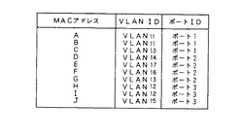
図2は、端末のグループ分けを図1に示すように行なったときのMACアドレスとVLANIDとポートIDとの対応関係を示すVLAN制御テーブルを示す図である。
グループ分けを図1に示すように行なった結果、各MACアドレスに対応するVLANIDの欄には、各1つのVLANIDのみ記録されることになる。ただしこの場合、例えばVLAN1に4つのVLANID、すなわちVLAN11,14,16,17が付されているように、1つのVLANに複数のVLANIDが付されることがあり、このため図2に示すVLAN制御テーブルの場合、図7に示すVLAN制御テーブルと異なり、異なる端末が同一のVLANに属しているか否かを示す情報が不足していることになる。
【0020】
そこで本実施形態では、以下に説明するような、結合管理テーブルを備える。
図3は、結合管理テーブルの一例を示す図である。
この結合管理テーブルは、各発信元端末が属する各単位グループの各VLANID(発信側VLANID)と、各受信先端末が属する各単位グループの各VLANID(受信側VLANID)とを索引情報とする2次元的なテーブルであり、この結合管理テーブルには、発信側VLANIDと受信側VLANIDとの2次元的な各座標点に、その座標の発信側VLANIDで示される単位グループに属する端末が発信元となり、その発信元端末から発信されたデータパケットを、その座標の受信側VLANIDで示される単位グループに属する端末が受信することができる(論理‘1’)か否(論理‘0’)かを示す結合情報が記憶されている。
【0021】
この結合管理テーブルにより、ある特定の端末どうしが通信可能な端末どうしであるか否か、即ち、同一のVLANに属している端末であるか否かを知ることができる。
図4は、本発明のネットワーク中継器の一実施形態を示すブロック図である。尚、本実施形態においても、この図4に示すネットワーク中継器を含むネットワークシステム全体は図5に示すシステムであるとする。
【0022】
この図4に示すネットワーク中継器11には、内部バス101に接続された、VLAN制御テーブル102、VLANIDラッチ103、結合管理テーブル104、制御プロセッサ105と、VLANを制御するVLAN制御プロセッサ106が備えられている。
VLAN制御テーブル102は、本実施形態では図2に示した内容のテーブルであり、連想メモリ(内容アドレス式メモリ;CAM(Content Addressable Memory))内に記憶されている。連想メモリは、1ワード分のデータのうちの一部分のビットパターンからなる検索データを入力し、その検索データと同一の部分データを持ったデータが内部に記憶されているか否を検索することのできる機能を備えたメモリである。連想メモリ自体は既に広く知られており、詳細説明は省略する。
【0023】
VLANIDラッチ103は、VLAN制御テーブル102から読み出されたVLANIDを一旦格納しておくためのものである。詳細は後述する。
結合管理テーブル104は、本実施形態では図3に示した内容のテーブルであり、通常のRAM(Random Access Memory)内に記憶されている。
【0024】
制御プロセッサ105は、VLAN制御テーブル(CAM)102、VLANIDラッチ103、および結合管理テーブル(RAM)104の動作タイミング等の制御を行ない、必要に応じてVLAN制御テーブル102や結合管理テーブル104の内容の書き換えを行なうためのものである。
VLAN制御プロセッサ106は、VLAN制御テーブル102や結合管理テーブル104との間で情報の授受を行ないながら、発信元端末から送信されてきたデータパケットを指定の受信先端末に向けて転送してもよいか否かを判定し、その判定結果に従ってデータパケットの転送制御を行なうためのものである。
【0025】
ネットワーク中継器11のいずれかのポート(図5参照)からデータパケットが入力されてくると、各ポートに対応して備えられた、そのポートからのデータパケットの入力、およびそのポートからのデータパケットの出力を担う各ポートコントローラ(図示せず)のうち、そのデータパケットが入力されてきたポートのポートコントローラにより、その入力されてきたデータパケット中の発信元MACアドレスが切り出されてVLAN制御プロセッサ106に入力される。VLAN制御プロセッサ106は、その発信元MACアドレスをVLAN制御テーブル(CAM)102に渡す。するとVLAN制御テーブル(CAM)102では、その入力されたMACアドレスが記憶されているか否かが検索され、記憶されていたときはそのMACアドレスに対応するVLANID(図2参照)が読み出され、VLANIDラッチ103にラッチされる。結合管理テーブル104を参照するにあたっては、図3に示すように、発信側のVLANIDと受信側のVLANIDとの双方が必要であり、ここでは受信側のVLANIDが揃うまで発信側のVLANIDがVLANIDラッチ103に一旦記憶される。
【0026】
VLAN制御テーブル(CAM)102に発信元MACアドレスが記憶されていなかったときは、このVLAN制御テーブル(CAM)102ではその新たなMACアドレスの登録が行なわれる。
次に、VLAN制御プロセッサ106には、ポートコントローラで切り出された受信先MACアドレスが入力され、VLAN制御プロセッサ106は、VLAN制御テーブル(CAM)102に、その受信先MACアドレスを渡す。VLAN制御テーブル(CAM)102では、この入力されたMACアドレスを基に再度検索が行なわれ、そのMACアドレスに対応するVLANID(受信側VLANID)とポートIDが読み出される。この読み出された受信側VLANIDは、VLANIDラッチ103にラッチされている発信側VLANIDとともに結合管理テーブル104に入力される。また、読み出されたポートIDは、VLAN制御プロセッサ106に入力される。
【0027】
結合管理テーブル(RAM)104では、入力された発信側VLANIDと受信側VLANIDとに基づいて、それら2つのVLANIDを座標とした座標点に格納されている論理‘1’又は論理‘0’の結合情報が読み出されてVLAN制御プロセッサ106に渡される。前述したように、結合情報が論理‘1’であることは、その発信元端末と受信先端末が同一のVLANに属していることを意味しており、したがって通信可能であることをあらわしており、一方、その結合情報が論理‘0’であったときは、その発信元端末と受信先端末とに共通のVLANは存在せず、したがって通信不能であることを表わしている。
【0028】
VLAN制御プロセッサ106は、結合管理テーブル(RAM)104から受け取った結合情報が通信可能であることを示す論理‘1’にあるときは、VLAN制御テーブル(CAM)102から受け取ったポートIDによって特定されるポートを管理するポートコントローラ(図示せず)に向けて、今回入力されてきたデータパケットをそのポートコントローラが管理するポートから出力するよう送信制御情報を出力する。その送信制御情報を受け取ったポートコントローラは、今回入力されてきたデータパケットを、そのデータパケットが入力されたポートを管理するポートコントローラから受け取り、自分が管理するポートから出力する。
【0029】
尚、VLAN制御テーブル102の検索において、VLAN制御プロセッサ106からVLAN制御テーブル102に渡したMACアドレスの検索に失敗した(VLAN制御テーブル102に、VLAN制御プロセッサ106から渡したMACアドレスと同一のMACアドレスが記憶されていなかった)ときは、その旨を表わすミスヒット情報がVLAN制御テーブル(CAM)102からVLAN制御プロセッサ106に渡される。そのときは、VLAN制御プロセッサ106は、あらかじめ定められた手順に従い、例えば宛先不明のデータパケットを処理するコントローラが接続された特別のポートからそのデータパケットを出力するよう指示する。
【0030】
このようにして、本実施形態においては、図1,図2を参照して説明したように各端末(各MACアドレス)が各1つのVLANIDを持ち、図3に示すような結合管理テーブルを備えて通信可能/不能を認識するようにしたため、結合管理テーブルという僅かなメモリ容量の増加だけで、データパケットの高速な転送制御が可能である。
【0031】
尚、上記実施形態では、同一のVLANに属している端末どうしの間ではいずれの方向にも通信が可能であることを前提としている。すなわち端末Aと端末FはVLAN1という同一のVLANに属しており(図1参照)、したがって端末Aが発信元端末、端末Fが受信先端末となることもでき、これとは逆に、端末Fが発信元端末、端末Aが受信先端末となることもできる。これにとどまるときは、この点に関しては、図7を参照して説明した手法あるいは図8を参照して説明した手法の場合と同様であるが、本発明の場合、例えば端末Aから端末Fにデータパケットを送信することができるものの、端末Fから端末Aには送信できないように一方通行の送信を可能とすることもできる。すなわち、図3に示す結合管理テーブルは図の左上から右下に延びる対角線X−X’を境界にして、論理‘1’と論理‘0’からなるパターンが線対称となっているが、非対称のパターンを作成することにより、例えばVLAN11に属する端末AからVLAN16に属する端末Fには送信可能とし、逆にVLAN16に属する端末FからVLAN11に属する端末Aには送信不能とすることもできる。
【0032】
また、図3に示す結合管理テーブルの各座標点には、論理‘1’と論理‘0’の二値からなる結合情報が記憶されているが、多値の結合情報を記憶し、例えば数値0は通信不能をあらわし、数値1以上は通信可能であって、かつその数値が1回の通信可能時間をあらわし、その通信可能時間だけ通信の仲介を行なうようにしてもよく、あるいは数値1以上は通信可能であって、かつその数値が通信可能回数をあらわし、1回通信を行なう毎にデクリメントするようにしてもよい。
【0033】
【発明の効果】
以上説明したように、本発明によれば、メモリ容量の増大化を抑えつつ通信の可否を高速に知ることができる。
【図面の簡単な説明】
【図1】端末のグループ分け方法の説明図である。
【図2】図1に示すように端末のグループ分けを行なったときのMACアドレスとVLANIDとポートIDとの対応関係を示すVLAN制御テーブルを示す図である。
【図3】結合管理テーブルの一例を示す図である。
【図4】本発明のネットワーク中継器の一実施形態を示すブロック図である。
【図5】ネットワークシステムの模式図である。
【図6】図5に示す端末とVLANとの関係を示す模式図である。
【図7】ネットワーク中継器における、各端末のアドレスと、各端末が属するVLANのVLANIDと、各端末が接続されたポートのポートIDとの対応関係を示すVLAN制御テーブルの一例を示す図である。
【図8】各端末のアドレス(MACアドレス)と、各端末が属するVLANとの、他の対応付方法を示す図である。
【符号の説明】
10ネットワークシステム
11 ネットワーク中継器
101 内部バス
102 VLAN制御テーブル(CAM)
103 VLANIDラッチ
104 結合管理テーブル
105 制御プロセッサ
106 VLAN制御プロセッサ[0001]
BACKGROUND OF THE INVENTION
The present invention relates to a network repeater called a router or the like that is provided in a network system and relays transmission of data packets as a lump of information.
[0002]
[Prior art]
2. Description of the Related Art Conventionally, there are network repeaters that relay transmission of data packets transmitted and received in a network system.
FIG. 5 is a schematic diagram illustrating an example of a network system.
Thisnetwork system includes a
[0003]
Here, when transmitting a data packet from the terminal A to the terminal D, the data packet transmitted from the terminal A which is a transmission source is input to the
[0004]
The terminal D knows that it is a data packet to be received from the reception destination address in the data packet sent via the
[0005]
FIG. 6 is a schematic diagram showing the relationship between the terminal shown in FIG. 5 and the VLAN. In the example shown here, the terminal A, the
[0006]
The
[0007]
[Problems to be solved by the invention]
FIG. 7 is a diagram showing an example of a VLAN control table showing the correspondence between the address of each terminal, the VLAN ID of the VLAN to which each terminal belongs, and the port ID of the port to which each terminal is connected in the network repeater. .
Here, the address (MAC address) of each terminal, the VLAN ID that identifies the VLAN to which each terminal belongs, and the port ID that identifies the port to which each terminal is connected are simply tabulated.
[0008]
For example, a terminal with MAC address A (terminal A) belongs to
[0009]
Here, for example, consider a case where a terminal J belonging to
In this case, the
[0010]
FIG. 8 is a diagram showing another method of associating each terminal address (MAC address) with the VLAN to which each terminal belongs.
Here, each MAC address (each terminal) has a bit array having a length of the maximum number n + 1 of VLANs, and each bit has a VLAN,
[0011]
For example, FIG. 8A shows a bit arrangement of n + 1 bits corresponding to the MAC address A (terminal A). Only
[0012]
When each terminal has which VLAN it belongs in such a bit array format, an AND operation is performed for each corresponding bit with respect to the bit array corresponding to the source terminal and the bit array corresponding to the receiving terminal. When the OR operation is performed on the entireAND operation result for each corresponding bit, when the OR operation result is logic '1', the source terminal and the receiving terminal belong to the same VLAN, and the OR operation result Is logical '0', it turns out that they do not belong to the same VLAN. That is, in the case of the bit array format as shown in FIG. 8, it is not necessary to perform successive comparison, and it can be determined whether or not they belong to the same VLAN by a simple calculation, and high-speed communication is possible.
[0013]
However, in the case of the format shown in FIG. 8, since a bit arrangement is required for each terminal, a large memory capacity is required, and a bit arrangement having the same length as the maximum number of VLANs is required. If the number is estimated to be small, the expandability is poor, and if the maximum number of VLANs is estimated to be large, there is a problem that an even larger amount of memory is required.
[0014]
In view of the above circumstances, an object of the present invention is to provide a network repeater having a configuration capable of knowing whether communication is possible at high speed while suppressing an increase in memory capacity.
[0015]
[Means for Solving the Problems]
The network repeater of the present invention that achieves the above object is connected to one or more terminals that act as at least one of a source and a destination of a data packet as a block of information including a source address and a destination address. A VLAN, which is a group of a plurality of terminals that are allowed to communicate with each other, is independent of the port to which each terminal is connected, and one terminal overlaps with a plurality of different VLANs. In a network repeater that relays transmission of data packets from a source terminal belonging to the sameVLAN to a destination terminal,
(1) The address of each terminal connected to any one of the plurality of ports, the port ID for mutually identifying the plurality of ports, only one common VLAN, or a plurality of common When one or more terminals belonging only to a VLAN are set as one unit group, all the terminals connected to any one of a plurality of ports are assigned to belong to only one unit group. VLAN control table storage means for storing a VLAN control table associated with a VLAN ID defined so that a plurality of unit groups are identified with each other. (2) Each unit group to which each source terminal belongs Corresponding to both the VLAN IDs of the VLAN IDs of each unit group to which each destination terminal belongs and Information indicating whether transmission of data packets from terminals belonging to the unit group identified by each VLAN ID on the source terminal side to terminals belonging to the unit group identified by each VLAN ID on the destination terminal side is permitted (3) A VLAN control table stored in the VLAN control table storage means when a data packet is input from any one of the plurality of ports. The VLAN ID of the unit group to which the source terminal belongs is known from the source address of the data packet, and the VLAN ID of the unit group to which the destination terminal belongs is known from the destination address of the data packet. The join management table stored in the storage means Referring to know whether or not the transmission of the data packet from the transmission source terminal to the reception destination terminal is permitted, and when the transmission is permitted, the data packet is A transfer control means for sending out from a connected port is provided.
[0016]
Here, in the network repeater of the present invention, the connection management table storage means is identified by each VLAN ID on the originating side corresponding to both VLAN IDs on the originating side and each VLAN ID on the receiving side. In addition to information indicating whether or not transmission of data packets from terminals belonging to the unit group to terminals belonging to the unit group identified by each VLAN ID on the receiving side is permitted, additional information related to data packet transfer control is stored. The combined management table may be stored.
[0017]
The “additional information related to data packet transfer control” refers to, for example, the communication time, the number of times of communication, and the like, but is not limited thereto. Each VLANID on the source terminal side and each VLANID on the destination terminal side Can be obtained as index information, as long as it is information relating to data packet transfer control.
[0018]
DETAILED DESCRIPTION OF THE INVENTION
Hereinafter, embodiments of the present invention will be described.
FIG. 1 is an explanatory diagram of a terminal grouping method in this embodiment.
Here, when one or more terminals belonging to only one common VLAN or only to a plurality of common VLANs are defined as one unit group, each of all ten terminals A to J is any one. Distribution is performed so as to belong to only one unit group, and a VLAN ID is assigned to each unit group thus distributed. That is, in the example shown here, since there are two terminals A and B that belong only to
[0019]
FIG. 2 is a diagram showing a VLAN control table showing the correspondence between MAC addresses, VLAN IDs, and port IDs when terminals are grouped as shown in FIG.
As a result of grouping as shown in FIG. 1, only one VLANID is recorded in the VLANID column corresponding to each MAC address. However, in this case, a plurality of VLANIDs may be attached to one VLAN, for example, as four VLANIDs, that is,
[0020]
Therefore, in the present embodiment, a join management table as described below is provided.
FIG. 3 is a diagram illustrating an example of the join management table.
This combined management table is a two-dimensional index in which each VLANID (originating VLANID) of each unit group to which each source terminal belongs and each VLANID (receiving VLANID) of each unit group to which each destination terminal belongs are index information. In this connection management table, terminals belonging to the unit group indicated by the sending side VLANID of the coordinates at the two-dimensional coordinate points of the sending side VLANID and the receiving side VLANID are the senders. A combination indicating whether a terminal belonging to the unit group indicated by the receiving side VLANID of the coordinates can receive a data packet transmitted from the transmission source terminal (logical '1') or not (logical '0') Information is stored.
[0021]
From this connection management table, it is possible to know whether or not specific terminals are communicable terminals, that is, whether or not they are terminals belonging to the same VLAN.
FIG. 4 is a block diagram showing an embodiment of the network repeater of the present invention. In this embodiment as well, the entire network system including the network repeater shown in FIG. 4 is the system shown in FIG.
[0022]
The
In the present embodiment, the VLAN control table 102 is a table having the contents shown in FIG. 2, and is stored in an associative memory (content addressable memory; CAM (Content Addressable Memory)). The associative memory can input search data consisting of a bit pattern of a part of one word of data, and can search whether data having the same partial data as the search data is stored therein. This is a memory with functions. The associative memory itself is already widely known, and detailed description thereof is omitted.
[0023]
The
The join management table 104 is a table having the contents shown in FIG. 3 in the present embodiment, and is stored in a normal RAM (Random Access Memory).
[0024]
The
The
[0025]
When a data packet is input from one of the ports of the network repeater 11 (see FIG. 5), the input of the data packet from the port provided for each port and the data packet from the port Of the port controllers (not shown) that are responsible for the output of the data, the port controller of the port to which the data packet is input extracts the source MAC address in the input data packet, and the
[0026]
When the source MAC address is not stored in the VLAN control table (CAM) 102, the new MAC address is registered in the VLAN control table (CAM) 102.
Next, the destination MAC address extracted by the port controller is input to the
[0027]
In the connection management table (RAM) 104, a logical '1' or a logical '0' is stored based on the input transmission side VLAN ID and reception side VLAN ID and stored at coordinate points with the two VLAN IDs as coordinates. Information is read and passed to the
[0028]
The
[0029]
In the search of the VLAN control table 102, the search of the MAC address passed from the
[0030]
In this way, in the present embodiment, as described with reference to FIGS. 1 and 2, each terminal (each MAC address) has one VLAN ID and includes a connection management table as shown in FIG. Therefore, it is possible to perform high-speed transfer control of data packets with only a slight increase in the memory capacity of the connection management table.
[0031]
In the above embodiment, it is assumed that communication is possible in any direction between terminals belonging to the same VLAN. That is, theterminal A and the terminal F belong to the same VLAN called VLAN1 (see FIG. 1), so the terminal A can be the source terminal and the terminal F can be the destination terminal. Can be the source terminal and terminal A can be the destination terminal. When this is the case, this point is the same as the method described with reference to FIG. 7 or the method described with reference to FIG. 8, but in the present invention, for example, from terminal A to terminal F. Although a data packet can be transmitted, one-way transmission can also be enabled so that terminal F cannot transmit to terminal A. That is, in the connection management table shown in FIG. 3, the pattern consisting of logic '1' and logic '0' is axisymmetrical with the diagonal line XX 'extending from the upper left to the lower right of the figure as a boundary. For example, the terminal A belonging to the
[0032]
Further, although the joint information composed of binary values of logic '1' and logic '0' is stored at each coordinate point of the joint management table shown in FIG. 0 indicates that communication is not possible, and a numerical value of 1 or more is communicable, and the numerical value indicates a communication possible time, and mediation of communication may be performed only for the communicable time, or a numerical value of 1 or more May be communicated, and the numerical value represents the number of communicable times, and may be decremented every time communication is performed.
[0033]
【The invention's effect】
As described above, according to the present invention, it is possible to know at high speed whether communication is possible while suppressing an increase in memory capacity.
[Brief description of the drawings]
FIG. 1 is an explanatory diagram of a terminal grouping method;
FIG. 2 is a diagram showing a VLAN control table showing a correspondence relationship between MAC addresses, VLAN IDs, and port IDs when terminals are grouped as shown in FIG. 1;
FIG. 3 is a diagram illustrating an example of a join management table.
FIG. 4 is a block diagram showing an embodiment of a network repeater of the present invention.
FIG. 5 is a schematic diagram of a network system.
6 is a schematic diagram showing the relationship between the terminal shown in FIG. 5 and a VLAN. FIG.
FIG. 7 is a diagram showing an example of a VLAN control table showing a correspondence relationship between the address of each terminal, the VLAN ID of the VLAN to which each terminal belongs, and the port ID of the port to which each terminal is connected in the network repeater. .
FIG. 8 is a diagram illustrating another association method between the address (MAC address) of each terminal and the VLAN to which each terminal belongs.
[Explanation of symbols]
10
103
Claims (2)
Translated fromJapanese前記複数のポートのうちのいずれかのポートに接続されてなる各端末のアドレスと、前記複数のポートを相互に識別するためのポートIDと、共通の1つのVLANのみ、もしくは共通の複数のVLANのみに属する1つ以上の端末を1つの単位グループとしたときに、前記複数のポートのうちのいずれかのポートに接続された全ての端末それぞれがいずれか1つの単位グループのみに属するように振り分けられてなる複数の単位グループが相互に識別されるように定義されてなるVLANIDとが対応づけられてなるVLAN制御テーブルを記憶するVLAN制御テーブル記憶手段、
各発信元端末が属する各単位グループの各VLANIDと、各受信先端末が属する各単位グループの各VLANIDとの双方のVLANIDに対応して、発信元端末側の各VLANIDによって識別される単位グループに属する端末から受信先端末側の各VLANIDによって識別される単位グループに属する端末へのデータパケットの送信が許容されているか否かを示す情報が格納されてなる結合管理テーブルを記憶する結合管理テーブル記憶手段、および
前記複数のポートのうちのいずれかのポートからデータパケットが入力されてきたときに、前記VLAN制御テーブル記憶手段に記憶されたVLAN制御テーブルを参照して、該データパケットの発信元アドレスから発信元端末が属する単位グループのVLANIDを知るとともに該データパケットの受信先アドレスから受信先端末が属する単位グループのVLANIDを知り、次いで、前記結合管理テーブル記憶手段に記憶された結合管理テーブルを参照して、該発信元端末から該受信先端末への該データパケットの送信が許容されているか否かを知り、該送信が許容されている場合に、該データパケットを、該受信先端末が接続されてなるポートから送り出す転送制御手段を備えたことを特徴とするネットワーク中継器。Communication was allowed while providing multiple ports to which one or more terminals that act as at least one of the source and destination of a data packet as a lump of information including a source address and a destination address can be connected A VLAN, which is a group of a plurality of terminals, is defined independently of a port to which each terminal is connected, and one terminal is allowed to belong to a plurality of different VLANs, and belongs to the sameVLAN . In a network repeater that relays transmission of data packets from a source terminal to a destination terminal,
The address of each terminal connected to any one of the plurality of ports, the port ID for mutually identifying the plurality of ports, and only one common VLAN or a plurality of common VLANs When one or more terminals belonging to only one unit are defined as one unit group, all the terminals connected to any one of the plurality of ports are allocated so as to belong to only one unit group. VLAN control table storage means for storing a VLAN control table associated with a VLAN ID defined so that a plurality of unit groups thus identified are mutually identified;
Corresponding to both VLANID of each VLANID of each unit group to which each source terminal belongs and each VLANID of each unit group to which each destination terminal belongs, a unit group identified by each VLANID on the source terminal side A join management table storage for storing a join management table in which information indicating whether or not transmission of data packets is allowed from a terminal belonging to a terminal belonging to a unit group identified by each VLAN ID on the receiving terminal side And a source address of the data packet by referring to the VLAN control table stored in the VLAN control table storage means when a data packet is input from any one of the plurality of ports. To know the VLANID of the unit group to which the source terminal belongs from Knowing the VLANID of the unit group to which the destination terminal belongs from the destination address of the data packet, and then referring to the association management table stored in the association management table storage means, from the source terminal to the destination terminal A transfer control means that knows whether or not transmission of the data packet is permitted, and that transmits the data packet from a port to which the receiving terminal is connected when the transmission is permitted; Feature network repeater.
Priority Applications (2)
| Application Number | Priority Date | Filing Date | Title |
|---|---|---|---|
| JP33715396AJP3662378B2 (en) | 1996-12-17 | 1996-12-17 | Network repeater |
| US08/989,241US6198741B1 (en) | 1996-12-17 | 1997-12-12 | Network interface apparatus for transmitting a data packet |
Applications Claiming Priority (1)
| Application Number | Priority Date | Filing Date | Title |
|---|---|---|---|
| JP33715396AJP3662378B2 (en) | 1996-12-17 | 1996-12-17 | Network repeater |
Publications (2)
| Publication Number | Publication Date |
|---|---|
| JPH10178442A JPH10178442A (en) | 1998-06-30 |
| JP3662378B2true JP3662378B2 (en) | 2005-06-22 |
Family
ID=18305947
Family Applications (1)
| Application Number | Title | Priority Date | Filing Date |
|---|---|---|---|
| JP33715396AExpired - Fee RelatedJP3662378B2 (en) | 1996-12-17 | 1996-12-17 | Network repeater |
Country Status (2)
| Country | Link |
|---|---|
| US (1) | US6198741B1 (en) |
| JP (1) | JP3662378B2 (en) |
Families Citing this family (42)
| Publication number | Priority date | Publication date | Assignee | Title |
|---|---|---|---|---|
| US7171453B2 (en)* | 2001-04-19 | 2007-01-30 | Hitachi, Ltd. | Virtual private volume method and system |
| JP4236398B2 (en)* | 2001-08-15 | 2009-03-11 | 富士通株式会社 | Communication method, communication system, and communication connection program |
| US7577143B1 (en)* | 2001-09-25 | 2009-08-18 | Juniper Networks, Inc. | Decoupling functionality related to providing a transparent local area network segment service |
| JP2003258842A (en)* | 2002-02-28 | 2003-09-12 | Ntt Docomo Inc | Packet communication system and transfer device |
| JP2004080323A (en)* | 2002-08-16 | 2004-03-11 | Fujitsu Ltd | LAN switching method and LAN switch |
| CN100471106C (en)* | 2003-04-29 | 2009-03-18 | 华为技术有限公司 | Method of Isolating Networks Based on Port Sets |
| US8151103B2 (en) | 2004-03-13 | 2012-04-03 | Adaptive Computing Enterprises, Inc. | System and method for providing object triggers |
| US8782654B2 (en) | 2004-03-13 | 2014-07-15 | Adaptive Computing Enterprises, Inc. | Co-allocating a reservation spanning different compute resources types |
| US20070266388A1 (en) | 2004-06-18 | 2007-11-15 | Cluster Resources, Inc. | System and method for providing advanced reservations in a compute environment |
| US8176490B1 (en) | 2004-08-20 | 2012-05-08 | Adaptive Computing Enterprises, Inc. | System and method of interfacing a workload manager and scheduler with an identity manager |
| WO2006053093A2 (en) | 2004-11-08 | 2006-05-18 | Cluster Resources, Inc. | System and method of providing system jobs within a compute environment |
| US9413687B2 (en) | 2005-03-16 | 2016-08-09 | Adaptive Computing Enterprises, Inc. | Automatic workload transfer to an on-demand center |
| US8863143B2 (en) | 2006-03-16 | 2014-10-14 | Adaptive Computing Enterprises, Inc. | System and method for managing a hybrid compute environment |
| US9231886B2 (en) | 2005-03-16 | 2016-01-05 | Adaptive Computing Enterprises, Inc. | Simple integration of an on-demand compute environment |
| ES2614751T3 (en) | 2005-04-07 | 2017-06-01 | Iii Holdings 12, Llc | Access on demand to computer resources |
| JP4622835B2 (en)* | 2005-12-07 | 2011-02-02 | 株式会社日立製作所 | Virtual computer system and network communication method thereof |
| US7817633B1 (en)* | 2005-12-30 | 2010-10-19 | Extreme Networks, Inc. | Method of providing virtual router functionality through abstracted virtual identifiers |
| CN100459583C (en)* | 2006-04-28 | 2009-02-04 | 杭州华三通信技术有限公司 | Data forwarding controlling method and apparatus |
| JP4501916B2 (en) | 2006-09-20 | 2010-07-14 | 日本電気株式会社 | I/O device sharing system, information processing device sharing system, and methods used therefor |
| US7898941B2 (en)* | 2007-09-11 | 2011-03-01 | Polycom, Inc. | Method and system for assigning a plurality of MACs to a plurality of processors |
| US8041773B2 (en) | 2007-09-24 | 2011-10-18 | The Research Foundation Of State University Of New York | Automatic clustering for self-organizing grids |
| JP5204684B2 (en)* | 2009-01-30 | 2013-06-05 | パナソニック株式会社 | Network management device |
| US9054990B2 (en) | 2009-10-30 | 2015-06-09 | Iii Holdings 2, Llc | System and method for data center security enhancements leveraging server SOCs or server fabrics |
| US9465771B2 (en) | 2009-09-24 | 2016-10-11 | Iii Holdings 2, Llc | Server on a chip and node cards comprising one or more of same |
| US8599863B2 (en) | 2009-10-30 | 2013-12-03 | Calxeda, Inc. | System and method for using a multi-protocol fabric module across a distributed server interconnect fabric |
| US9876735B2 (en) | 2009-10-30 | 2018-01-23 | Iii Holdings 2, Llc | Performance and power optimized computer system architectures and methods leveraging power optimized tree fabric interconnect |
| US20130107444A1 (en) | 2011-10-28 | 2013-05-02 | Calxeda, Inc. | System and method for flexible storage and networking provisioning in large scalable processor installations |
| US20110103391A1 (en) | 2009-10-30 | 2011-05-05 | Smooth-Stone, Inc. C/O Barry Evans | System and method for high-performance, low-power data center interconnect fabric |
| US9077654B2 (en) | 2009-10-30 | 2015-07-07 | Iii Holdings 2, Llc | System and method for data center security enhancements leveraging managed server SOCs |
| US10877695B2 (en) | 2009-10-30 | 2020-12-29 | Iii Holdings 2, Llc | Memcached server functionality in a cluster of data processing nodes |
| US9311269B2 (en) | 2009-10-30 | 2016-04-12 | Iii Holdings 2, Llc | Network proxy for high-performance, low-power data center interconnect fabric |
| US11720290B2 (en) | 2009-10-30 | 2023-08-08 | Iii Holdings 2, Llc | Memcached server functionality in a cluster of data processing nodes |
| US9680770B2 (en) | 2009-10-30 | 2017-06-13 | Iii Holdings 2, Llc | System and method for using a multi-protocol fabric module across a distributed server interconnect fabric |
| US9648102B1 (en) | 2012-12-27 | 2017-05-09 | Iii Holdings 2, Llc | Memcached server functionality in a cluster of data processing nodes |
| US9092594B2 (en) | 2011-10-31 | 2015-07-28 | Iii Holdings 2, Llc | Node card management in a modular and large scalable server system |
| US8989188B2 (en)* | 2012-05-10 | 2015-03-24 | Cisco Technology, Inc. | Preventing leaks among private virtual local area network ports due to configuration changes in a headless mode |
| JP2014230046A (en)* | 2013-05-22 | 2014-12-08 | 株式会社ナカヨ | Ip address allocation server having control function by hub |
| US10051204B2 (en)* | 2014-11-18 | 2018-08-14 | Caavo Inc | Seamless setup and control for home entertainment devices and content |
| WO2016081624A1 (en) | 2014-11-18 | 2016-05-26 | Branch Media Labs, Inc. | Automatic identification and mapping of consumer electronic devices to ports on an hdmi switch |
| WO2016081636A1 (en) | 2014-11-18 | 2016-05-26 | Branch Media Labs, Inc. | Seamless setup and control for home entertainment devices and content |
| WO2018148439A1 (en) | 2017-02-10 | 2018-08-16 | Caavo Inc | Determining state signatures for consumer electronic devices coupled to an audio/video switch |
| CN108449443B (en)* | 2018-03-21 | 2020-11-03 | 常熟理工学院 | Method for realizing address configuration of all-IP wireless network |
Family Cites Families (3)
| Publication number | Priority date | Publication date | Assignee | Title |
|---|---|---|---|---|
| US5390173A (en)* | 1992-10-22 | 1995-02-14 | Digital Equipment Corporation | Packet format in hub for packet data communications system |
| EP0594196B1 (en)* | 1992-10-22 | 1999-03-31 | Cabletron Systems, Inc. | Address lookup in packet data communications link, using hashing and content-addressable memory |
| US5959989A (en)* | 1997-06-25 | 1999-09-28 | Cisco Technology, Inc. | System for efficient multicast distribution in a virtual local area network environment |
- 1996
- 1996-12-17JPJP33715396Apatent/JP3662378B2/ennot_activeExpired - Fee Related
- 1997
- 1997-12-12USUS08/989,241patent/US6198741B1/ennot_activeExpired - Fee Related
Also Published As
| Publication number | Publication date |
|---|---|
| JPH10178442A (en) | 1998-06-30 |
| US6198741B1 (en) | 2001-03-06 |
Similar Documents
| Publication | Publication Date | Title |
|---|---|---|
| JP3662378B2 (en) | Network repeater | |
| US6801950B1 (en) | Stackable network unit including register for identifying trunk connection status of stacked units | |
| US5434863A (en) | Internetworking apparatus for connecting plural network systems and communication network system composed of plural network systems mutually connected | |
| EP1035685B1 (en) | Data communication system with distributed multicasting | |
| AU685293B2 (en) | Extended domain computer network using standard links | |
| US6798775B1 (en) | Virtual LANs over a DLSw network | |
| JP2735390B2 (en) | Hub for partitioned virtual area network with shared media access | |
| US6112251A (en) | Virtual local network for sending multicast transmissions to trunk stations | |
| US7835306B2 (en) | Translating MST instances between ports of a bridge in a computer network | |
| US6807179B1 (en) | Trunking arrangement in a network switch | |
| US6807182B1 (en) | Stacked network devices including a protocol engine and distributed trunk ports and method of operating same | |
| US20030172188A1 (en) | Virtual local area network connecting equipment | |
| US20030061533A1 (en) | Multi-device link aggregation | |
| EP1065843A2 (en) | Load sharing/trunking in a communication device | |
| JPH0799837B2 (en) | Method and apparatus for transmitting message package | |
| CN101325554B (en) | Method for establishing route, forwarding chip and three-layer switchboard | |
| EP0860958B1 (en) | Virtual network architecture | |
| MX2007003778A (en) | Ring network, communication device, and operational management method used for the ring network and communication device . | |
| US6510151B1 (en) | Packet filtering in connection-based switching networks | |
| US7447223B2 (en) | Switching mesh with broadcast path redundancy | |
| US6469987B1 (en) | Virtual local area network with trunk stations | |
| KR20060090219A (en) | How to Switch Packets in Transmission Media Including Multiple Stations Connected Using Different Links | |
| US7657619B1 (en) | Method and system for maintaining a loop-free topology across multiple spanning trees in a virtual local area network | |
| JP3315033B2 (en) | Network frame repeater | |
| JPH0458215B2 (en) |
Legal Events
| Date | Code | Title | Description |
|---|---|---|---|
| A977 | Report on retrieval | Free format text:JAPANESE INTERMEDIATE CODE: A971007 Effective date:20050117 | |
| A131 | Notification of reasons for refusal | Free format text:JAPANESE INTERMEDIATE CODE: A131 Effective date:20050125 | |
| A521 | Written amendment | Free format text:JAPANESE INTERMEDIATE CODE: A523 Effective date:20050228 | |
| TRDD | Decision of grant or rejection written | ||
| A01 | Written decision to grant a patent or to grant a registration (utility model) | Free format text:JAPANESE INTERMEDIATE CODE: A01 Effective date:20050322 | |
| A61 | First payment of annual fees (during grant procedure) | Free format text:JAPANESE INTERMEDIATE CODE: A61 Effective date:20050323 | |
| R150 | Certificate of patent or registration of utility model | Free format text:JAPANESE INTERMEDIATE CODE: R150 | |
| FPAY | Renewal fee payment (event date is renewal date of database) | Free format text:PAYMENT UNTIL: 20080401 Year of fee payment:3 | |
| FPAY | Renewal fee payment (event date is renewal date of database) | Free format text:PAYMENT UNTIL: 20090401 Year of fee payment:4 | |
| FPAY | Renewal fee payment (event date is renewal date of database) | Free format text:PAYMENT UNTIL: 20090401 Year of fee payment:4 | |
| FPAY | Renewal fee payment (event date is renewal date of database) | Free format text:PAYMENT UNTIL: 20100401 Year of fee payment:5 | |
| FPAY | Renewal fee payment (event date is renewal date of database) | Free format text:PAYMENT UNTIL: 20100401 Year of fee payment:5 | |
| FPAY | Renewal fee payment (event date is renewal date of database) | Free format text:PAYMENT UNTIL: 20110401 Year of fee payment:6 | |
| LAPS | Cancellation because of no payment of annual fees |