JP3657661B2 - Safety trocar - Google Patents
Safety trocarDownload PDFInfo
- Publication number
- JP3657661B2 JP3657661B2JP23459095AJP23459095AJP3657661B2JP 3657661 B2JP3657661 B2JP 3657661B2JP 23459095 AJP23459095 AJP 23459095AJP 23459095 AJP23459095 AJP 23459095AJP 3657661 B2JP3657661 B2JP 3657661B2
- Authority
- JP
- Japan
- Prior art keywords
- obturator
- trocar
- shield
- distal end
- tissue
- Prior art date
- Legal status (The legal status is an assumption and is not a legal conclusion. Google has not performed a legal analysis and makes no representation as to the accuracy of the status listed.)
- Expired - Fee Related
Links
- 239000005300metallic glassSubstances0.000abstractdescription6
- 210000001519tissueAnatomy0.000description40
- 210000003815abdominal wallAnatomy0.000description4
- 206010033675panniculitisDiseases0.000description4
- 210000004304subcutaneous tissueAnatomy0.000description4
- 210000001835visceraAnatomy0.000description4
- 238000005553drillingMethods0.000description3
- 230000035876healingEffects0.000description3
- 208000034693LacerationDiseases0.000description2
- 238000010586diagramMethods0.000description2
- 238000002674endoscopic surgeryMethods0.000description2
- 208000014674injuryDiseases0.000description2
- 239000000463materialSubstances0.000description2
- 239000002184metalSubstances0.000description2
- 229910052751metalInorganic materials0.000description2
- 230000000149penetrating effectEffects0.000description2
- 229910001220stainless steelInorganic materials0.000description2
- 239000010935stainless steelSubstances0.000description2
- 238000001356surgical procedureMethods0.000description2
- 230000008733traumaEffects0.000description2
- 229910000831SteelInorganic materials0.000description1
- 239000000919ceramicSubstances0.000description1
- 230000000694effectsEffects0.000description1
- 230000001771impaired effectEffects0.000description1
- 150000002739metalsChemical class0.000description1
- 230000002093peripheral effectEffects0.000description1
- 210000004872soft tissueAnatomy0.000description1
- 239000010959steelSubstances0.000description1
Images


Classifications
- A—HUMAN NECESSITIES
- A61—MEDICAL OR VETERINARY SCIENCE; HYGIENE
- A61B—DIAGNOSIS; SURGERY; IDENTIFICATION
- A61B17/00—Surgical instruments, devices or methods
- A61B17/34—Trocars; Puncturing needles
- A61B17/3417—Details of tips or shafts, e.g. grooves, expandable, bendable; Multiple coaxial sliding cannulas, e.g. for dilating
- A—HUMAN NECESSITIES
- A61—MEDICAL OR VETERINARY SCIENCE; HYGIENE
- A61B—DIAGNOSIS; SURGERY; IDENTIFICATION
- A61B17/00—Surgical instruments, devices or methods
- A61B17/34—Trocars; Puncturing needles
- A61B17/3494—Trocars; Puncturing needles with safety means for protection against accidental cutting or pricking, e.g. limiting insertion depth, pressure sensors
- A61B17/3496—Protecting sleeves or inner probes; Retractable tips
Landscapes
- Health & Medical Sciences (AREA)
- Surgery (AREA)
- Life Sciences & Earth Sciences (AREA)
- Medical Informatics (AREA)
- Animal Behavior & Ethology (AREA)
- Engineering & Computer Science (AREA)
- Biomedical Technology (AREA)
- Heart & Thoracic Surgery (AREA)
- Pathology (AREA)
- Molecular Biology (AREA)
- Nuclear Medicine, Radiotherapy & Molecular Imaging (AREA)
- General Health & Medical Sciences (AREA)
- Public Health (AREA)
- Veterinary Medicine (AREA)
- Surgical Instruments (AREA)
- Materials For Medical Uses (AREA)
- Holo Graphy (AREA)
- Eye Examination Apparatus (AREA)
Abstract
Description
Translated fromJapanese【0001】
【発明の属する技術分野】
本出願は、腹腔鏡もしくは関節鏡手術において組織穿孔のために用いられるトロカールに係り、特に栓塞子の先端が組織を穿孔した後この栓塞子先端を直ちに覆う安全装置を備えたトロカールに関する。
【0002】
【従来の技術】
トロカールは普通、トロカールチューブと栓塞子の二つの主要な部品を有する。トロカールチューブもしくはカニューレは、皮膚を貫通して挿入される。腹腔鏡や関節鏡手術を行うためには、体腔にアクセスしなければならない。皮膚に穿孔するためには、トロカールチューブの遠方端を皮膚に当て、栓塞子をこのトロカールチューブに挿入する。栓塞子の手前側を押すと、栓塞子の先端は、体腔内に入り込むまで、皮膚に押し付けられていく。そして皮膚が穿孔されると、トロカールチューブは、栓塞子によって開けられた孔に挿入され、一方栓塞子は引き取られる。そして、トロカールチューブは、体腔への通路として残される。
【0003】
ところで、このようなトロカールを用いた場合は、皮膚と皮下組織の穿孔にかなり大きな力が要求されることがある。そして、栓塞子先端が最終的に皮下組織に穿孔すると、穿孔に対する抵抗が突然なくなり、栓塞子の先端は、体内の器官を穿孔して裂傷その他の外傷を引き起こすような位置に到達してしまう。このような患者に対する危険を避けるため、これまでに、トロカールチューブの内部で栓塞子を包囲する、ばねを装填した環状のシールドを備えたトロカールが開発された。栓塞子が身体に穿孔するとき、シールドの遠方端は、栓塞子が安全シールドの通過を可能にする大きさの径をもつ孔を形成するまで、皮膚を押圧する。このとき、このような孔が形成されると、組織のばね装填シールドに対する抵抗はなくなり、シールドは、ばねの力によって、栓塞子の先端を覆いながら体腔内に入り込む。シールドは、こうして体内器官を栓塞子先端との手違いによる接触から保護する。このような安全シールドを備えたトロカールは、例えば米国特許第4,535,773 号に記載されている。
【0004】
このようなトロカールにある環状のシールドにあっては、しかし、安全シールドがばねの力で前方に進めるよう組織の押圧に対する抵抗が充分に減少する前に、栓塞子で形成する切開がかなり大きな径に広がらなければならない。すなわち、シールドが体腔内に充分に入り込めるのは、切開口がシールドの径分だけ開いたときに限られる。したがって、栓塞子が長手のテーパ付けられた切開用の先端を有するときは、この栓塞子先端は、切開口が安全シールドの通過を許すよう充分に拡大される前に、かなりの距離まで体腔内に入らなければならない。したがって、体腔へのアクセスが得られた後できるだけ早く栓塞子を覆うべくばねの力で前方に進む安全シールドの提供が望まれている。
【0005】
米国特許第5,066,288 号(Deniega)によれば、丸めた弾丸形の遠方端を有するトロカール栓塞子用の安全シールドが提供される。そして、この遠方端には、皮膚穿孔の際に栓塞子の先端が通過、延び出る、栓塞子先端の形状・大きさに合わせたスロットが形成される。安全シールドは、栓塞子先端の形状・大きさに合わせた遠方端を有するため、栓塞子の先端から安全シールドの遠方までトロカール全体がスムーズに移動し、安全シールドは、栓塞子の先端に密接して続き、組織を貫通する。栓塞子の丸めた遠方端は、切開部を形成するとき、切開部の周縁にきわめて近い箇所で皮膚と組織を押圧し、体腔へのアクセスが得られるや否やシールドがばねで前方へ付勢されるよう、切開部の拡大を補助する。
【0006】
このようなトロカールの好ましい特徴は、栓塞子の挿入・引き込みの際にトロカールチューブ内で栓塞子がスムーズにスライドすることである。この要求には対立するが、組織の穿孔径がトロカールチューブのそれと同じになるよう、栓塞子は、トロカールチューブとほぼ同じ径をもつように形成しなければならない。このため、栓塞子の径とトロカールチューブ内径の間の許容差は、一般的に小さくなる。トロカールチューブの手前端は、バルブも設けるため、また複雑になる。このバルブは、トロカールチューブと体腔をガスで充填・膨脹させながら栓塞子を後退させる際、手前端を封止するのに必要である。ヒンジ付きフラップないしトランペットバルブの形状をしたバルブは、栓塞子を押圧するようにばねを装填するため、栓塞子がトロカールチューブから後退するとき、バルブは自動的に閉止する。しかし一方で、バルブは栓塞子を押圧するため、栓塞子の進入と後退を摩擦によって妨害する。これら許容差の問題のため、これまで、トロカールカニューレのシャフトに一致し、また栓塞子が内部をスライドする安全シールドの内径より径が大きな栓塞子は得られていない。
【0007】
さらに、栓塞子が皮下組織を完全に貫通したときにも、栓塞子が体腔に突然延び出るのが防止されるため、患者の安全も確保される。先の米国特許第5,066,288 号(Deniega)によれば、皮下組織の穿孔を進める際、栓塞子の段階的な前進のみを許容する手段を設けている。このような栓塞子の段階的な前進は、ラチェットやねじ機構によって達成することができる。しかし、この特許でも、安全シールドの遠方端がどのような位置にあっても安全シールドの端を越えて栓塞子先端が露出するのを最小にするという問題は解決されていない。
【0008】
【発明が解決しようとする課題】
そこで、本発明の目的は、安全シールドに収められた栓塞子先端の切開端がトロカールカニューレの内径に対応するような、安全シールドを装備したトロカールを提供することである。このようなトロカールによれば、腹壁に穿孔する際の力を減じることができる。
【0009】
【課題を解決するための手段】
栓塞子の先端は、近年使われ始めた非晶質型の金属からつくるのが望ましい。アモルファススチールなどの非晶質金属は、これまでトロカール栓塞子の先端など組織の穿孔を目的とする医療分野では使用されていなかった。
【0010】
さらに、本発明は、円錐形のシールドを備えた安全シールド付きトロカールを提供することも目的とする。この型のシールドは、組織穿孔部の拡大を容易にし、また種々の栓塞子先端に適合することができる。
【0011】
この種の安全シールドにおいては直径の大きさのスロットを設けるのが好ましい。このスロットは、ナイフエッジ(ナイフ状の端部)の通路となり、栓塞子が腹壁に穿孔するときには、このスロットに対応して、栓塞子の直径に相当するスリットを形成される。また、このようなスリットは、穿孔した組織の治癒を容易にし、また標準的なトロカールによって形成される三角形状の開口に対して、メス状の切り口をつくることができる。
【0012】
さらに、両面刃を備えただけの径が小さい(5mm以下)トロカールの栓塞子は、腹壁によりよく穿孔するためには、なんらかの塊が必要である。本発明はこのような塊をトロカール栓塞子に設けることも目的とする。
【0013】
これらの目的は、栓塞子ハンドルに連結され、鋭利な先端を有する栓塞子を備えたトロカールにおいて達成される。この栓塞子は、カニューレハンドルに連結されたカニューレに挿入される。カニューレ自体は開口筒であり、内径を有する。また、このトロカールは、栓塞子ハンドル内でばねを装填された安全シールドを備える。この安全シールドは、栓塞子の先端を覆うことができる。安全シールドは、内部に栓塞子の先端を通す開口部を有する。栓塞子の先端は、この安全シールドの開口部を通じて延び出る際、カニューレの内壁に接する。栓塞子の先端は、非晶質の金属から形成され、ナイフエッジのような湾曲した輪郭を有する。ナイフエッジは、ノコギリ刃状にしてもよい。また、安全シールドは、体組織内に入り込みやすいよう円錐形にされ、またカニューレの内径方向一杯に延びるスリットを有する。ブレード(栓塞子の先端に設けられる刃)は、安全シールドの一部に連結される。
【0014】
したがって、本発明のトロカールを使えば、穿孔が容易になり、穿孔跡の治癒も早くなる。また、きわめて正確な形状の金属を用いるため、腹壁の穿孔もすみやかに行うことができる。本発明のトロカールは、組織を押圧する一方で、栓塞子の先端を覆う安全シールドで保護される。両面ブレードに取り付けられる安全シールドは、体組織穿孔の手段としては理想的なものである。本発明によれば、特に5mm以下の小さなトロカールにおいて、栓塞子がきわめて効果的に使えるようになる。
【0015】
【発明の実施の形態】
本発明は、添付の図面を参照した以下の詳細な記述により、より明確に理解されるであろう。
【0016】
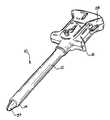
本発明の原理に従って構成される安全トロカールを図1と図8に示す。トロカール10は、開口した遠方端14と開口したフランジ付きの手前端16を有するトロカールチューブもしくはカニューレ12を備える。トロカールハンドル18の手前端16には、ガスケットリング22で包囲された開口20が設けられる。
【0017】
栓塞子24は、トロカールカニューレ12内にスライドおよび取り外し可能に収められ、カニューレハンドル18の開口20を通してカニューレハンドル18およびカニューレ12に挿入される。栓塞子24は、栓塞子ハンドル28内にスライドして入り込み、また栓塞子ハンドル28内で回転することもできる。栓塞子ハンドルは栓塞子の手前端26にあり、栓塞子24の遠方端は、ナイフエッジのように鋭利に尖らせる。図1と8に示す安全トロカールは、カニューレ12の遠方端を組織に当て、栓塞子ハンドル28を押して柔らかい組織に穴を開けるために用いられる。栓塞子ハンドル28に圧力を加えると、安全シールド34は、栓塞子ハンドル28内でばね36を圧縮し始め、安全シールド34は栓塞子ハンドル28内に後退する。このように安全シールドが後退すると、組織穿孔用の栓塞子のナイフエッジ32が露出する。
【0018】
図7(b)は、安全シールド34が栓塞子ハンドル28内で充分に圧縮され、栓塞子のナイフエッジ32が安全シールド34とカニューレ12の遠方端から充分に露出した状態を示す。栓塞子のナイフエッジ32が組織の内表面を破ると、ばねを装填した安全シールド34は、ばねの力で栓塞子遠方端の回りに進み出て、栓塞子のナイフエッジ32を被覆し、ナイフエッジ32が穿孔した組織の内部で体内器官と不意に接触するのを防止する。
【0019】
本発明による安全シールドを装備したトロカールが作動する模様は、図1、2および7(b)に示す。図1は、安全シールド34の端部がカニューレ12の遠方端14から延び出るよう、トロカールハンドル18の内側にカニューレを付けた状態のトロカールの斜視図である。図2は、カニューレ12の遠方端12の底面図である。図5は、栓塞子24を覆うシールド34のない栓塞子24のみの側面図である。図7(b)は、図1のトロカールの遠方端を示す図であり、栓塞子24のナイフエッジ32は延び出て、栓塞子の遠方端30は、安全シールド34から離れている。図7(a)において、栓塞子の遠方端30は、図7(b)に示した安全シールド34に覆われた状態にある。
【0020】
これまでは本発明の一般的な構成について説明してきたが、以下には本発明の種々の態様をより詳しく説明する。第一に、図1、5、7(a)、7(b)および8に示すように、栓塞子の遠方端30を見てみると、この栓塞子遠方端30は、栓塞子の直径方向に延びるナイフエッジ32を有する。すなわち、栓塞子遠方端30は、鋭利なナイフエッジ32を形成する二つの平面40を有する。ナイフエッジ32は、カニューレの内径L一杯に横断方向に延びる。こうしてナイフエッジ32の側端は、カニューレ12の側面Sと同一の高さになる。このような構成・配置にすると、組織の穿孔・貫通に必要な力を減らすことができる。これは、栓塞子は、このようなナイフエッジ32があると、カニューレ12の端部42に隣接して動くことができるからである。したがって、組織Tがカニューレ12に触れたときでも、カニューレ12によって組織がさらに拡がることはない。これは図3に示した従来のトロカールによる場合と対照的で、組織は栓塞子の先端と安全シールドの間に挟み込まれることはない。
【0021】
ナイフエッジ32は、本発明の安全シールド34とともに用いられる。図をみれば、安全シールド34は、円錐形であることに気がつくであろう。通常プラスチックからつくられるこの円錐形安全シールドは、組織をきわめてなだらかに広げていく。勿論、この円錐形は、孔の所望の鋭利さに応じて、より急にもまたより浅くすることもできる。当然のことながら、より急な(長い)円錐形の方が、穿孔は容易になる。さらに、安全シールド34はカニューレの内壁に接するため、安全シールド34は、穿孔部空の組織の拡大もより巧妙に行うことができる。
【0022】
図2の底面図にならって、ナイフエッジ32は、直径方向にやや長いスリットを形成する。このスリットは、従来のトロカールによって形成される三角形の切り口とは異なる。この切り口は、メスのそれによく似ている。よって、皮膚の表面において閉じ合わせなければならない組織が少ないため、組織の治癒はより早く行われる。また、このナイフエッジ32と安全シールド36の組合せにより、組織が非常に容易に穿孔される、すなわち穿孔に必要な力が軽減される。
【0023】
図6(a)と6(b)には、ともに直径方向に延びる形状ではあるが、ナイフエッジ32Aと32Bの二つの異なる形状を示した。すなわち、一方のナイフエッジ32Aは、ノコギリ状である。このノコギリ状のエッジ32Aは、より容易に組織を切断することができる。もちろん、ノコギリ状のエッジ32Aは、組織とより広い面積で接触するが、ナイフエッジの形・大きさが損なわれることはない。
【0024】
他方、図6(b)には、通常のメス型をした栓塞子の先端32Bを示す。このメス型先端をもつ栓塞子をこれと対応する安全シールドと用いる場合、トロカールの使用者は、メスを用いるときと同じ保持姿勢で組織に穿孔することができる。このような先端32Bをもつ栓塞子は、特に内視鏡手術に有用である。これらのナイフエッジは、カニューレ12の側面から10〜60°の切り込み角度をなす方位で適用される。
【0025】
実際、本発明の栓塞子24は、穿孔具としても使うことができる。すなわち、本発明の栓塞子24はメスのように組織を貫通するのに有用であるため、この栓塞子24は、組織を内部で切断する際、長いカニューレの下で内視鏡を使いながら使用するのに借用されることがある。この機構の安全シールド34は、所望の場合だけ被覆され、組織の穿孔後自動的には被覆されないように製造される。
【0026】
本発明の栓塞子32は、本出願人出願の米国特許出願第786,752 号に記載されたように、非晶質の金属からつくられる。この非晶質金属は、約0.001 インチの非常に小さな寸法でも、非常に正確に成形・寸法合わせをすることができる。こうして、この機構のナイフエッジは、穿孔した組織にもきわめて容易に適用することができる。また、非晶質の金属は、図6(a)にあるようなノコギリ状に形成できるため、このようなナイフエッジは、内視鏡手術に用いることができる。しかし、ナイフエッジの材料には、セラミックやステンレススチールのような他の材料も使用することができる。
【0027】
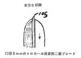
図9、10および11には、安全シールドとブレードの他の組合せを示した。これらの図から分るように、カニューレ(図1の符号12で示したものと同じ)に挿入される栓塞子のシャフト100の一部は、固定安全シールド106となっている。固定シールド106の遠方端には、図1ないし8に示したブレードに似たステンレススチール製の鋭利なブレード104が設けられる。この安全シールドとブレードの組合せ(図10に示す)は、ブレード104がカニューレの周壁に沿って直径方向に延びるよう、カニューレ12の断面の半分を占める。安全シールドの固定部106の反対側には、ばねを装填したシールド部分102が設置される。このシールド部分102は、ばね(図示せず)によって固定部106に連結される。この可動部分102の遠方端108は、固定シールド部分106上にあるブレード104の先端まで延びている。したがって、この可動シールド部分102が最も遠方側の位置にあって、公知のロック手段(図示せず)によってこの位置にロックされているときは、ブレード104は、組織を切断することのないよう保護される。他方、可動シールド部分102がロックされていないときは、この可動シールド部分102はカニューレに向けて手前側に後退することができる。このとき、ブレード104は露出され、ブレードの先端105は、自由に組織を切断できるようになる。可動安全シールド部分102に対する圧力が除かれると、可動シールド102はその最も延び切った位置に戻り、この位置でロックされる。前にも述べたように、このとき、ブレードは組織を切断することはできない。
【0028】
この態様は、きわめて薄い(0.005 インチ未満)ブレード104が固定シールド106によって補強されるため、小さな(5mm以下)トロカールに特に適している。ブレード104に付け加えられる塊(シールド)は、組織と切断する際のプラットホームにもなる。
【0029】
本発明のトロカールは多くの改良点を有するが、本明細書の記載からは多くの均等物が洞察されるであろう。しかし、このような均等物は、本明細書に記載した特許請求の範囲によって、本発明の範囲内のものとして包含されるべきものである。
【0030】
本発明の具体的な実施態様は以下の通りである。
(A)トロカールの栓塞子であって、
遠方端および手前端を有する長手シャフトと、
前記シャフトの遠方端において前記シャフトから延びるブレードと、
前記ブレードに取り付けられる固定シールドと、
前記ブレードと組み合わされ、前記固定シールドに対してスライド可能な可動シールドを備える栓塞子。
1)前記シールドは、前記シャフトを軸方向に二等分する上記実施態様(A)記載の栓塞子。
2)前記シールドは、前記ブレードの遠方端でロックされる上記実施態様(A)記載の栓塞子。
3)前記トロカールの栓塞子は、少なくともこの栓塞子が挿入可能なカニューレを備えるトロカールシステムの一部をなす上記実施態様(A)記載の栓塞子。
4)前記カニューレは口径が5mmないしこれより小さい上記実施態様3)記載の栓塞子。
5)前記可動シールドは、前記トロカール栓塞子の軸方向に沿って往復運動をする上記実施態様(A)記載の栓塞子。
6)前記ブレードは、前記固定シールドの遠方端から延びる上記実施態様(A)記載の栓塞子。
7)前記ブレードはその遠方端において半円状である上記実施態様6)記載の栓塞子。
(B)トロカールであって、
栓塞子が挿入可能なカニューレと、
遠方端および手前端を有する長手シャフトと、
前記シャフトの遠方端において前記シャフトから延びるブレードと、
前記ブレードに取り付けられる固定シールドと、
前記ブレードと組み合わされ、前記固定シールドに対してスライド可能な可動シールドを備えるトロカール。
【0031】
【発明の効果】
以上説明したように、本発明によれば、トロカールの栓塞子先端が組織を貫通した後、勢い余って体内の器官を穿孔し裂傷その他の外傷を引き起こすような事態は防止される。
【図面の簡単な説明】
【図1】円錐形の安全シールドを備えたトロカールの斜視図。
【図2】図1のトロカールの底面図。
【図3】従来の栓塞子先端が組織を穿孔する模様を示す図。
【図4】本発明の栓塞子先端が組織を穿孔する模様を示す図。
【図5】安全シールドなしで示した本発明の栓塞子先端の側面図。
【図6】(a)と(b)はともに本発明の栓塞子先端の他の態様を示す図。
【図7】(a)は図5の栓塞子先端と安全シールドの組合せを示す図、(b)は(a)の栓塞子先端が露出した状態の安全シールドを示す図。
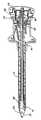
【図8】図1に示したトロカールの断面図。
【図9】ブレードと安全シールドの組合せの変形例を示す側面図。
【図10】図9に示したブレードと安全シールドの組合せの平面図。
【図11】図9に示したブレードと安全シールドの組合せの切開状態を示す図。
【符号の説明】
10 トロカール
12 カニューレ
24 栓塞子
26 栓塞子の手前端
30 栓塞子の遠方端
32 ナイフエッジ
102 可動シールド
106 固定シールド[0001]
BACKGROUND OF THE INVENTION
The present application relates to a trocar used for tissue perforation in laparoscopic or arthroscopic surgery, and more particularly to a trocar equipped with a safety device that immediately covers the obturator tip after the obturator tip has perforated the tissue.
[0002]
[Prior art]
Trocars usually have two main parts: a trocar tube and an obturator. A trocar tube or cannula is inserted through the skin. To perform laparoscopic or arthroscopic surgery, the body cavity must be accessed. To pierce the skin, the distal end of the trocar tube is applied to the skin and an obturator is inserted into the trocar tube. When the front side of the obturator is pushed, the tip of the obturator is pressed against the skin until it enters the body cavity. Then, when the skin is pierced, the trocar tube is inserted into the hole opened by the obturator, while the obturator is withdrawn. The trocar tube is then left as a passage to the body cavity.
[0003]
By the way, when such a trocar is used, a considerably large force may be required to perforate skin and subcutaneous tissue. When the obturator tip finally punctures the subcutaneous tissue, resistance to the puncture suddenly disappears, and the tip of the obturator reaches a position where the internal organ is punctured to cause a laceration or other trauma. To avoid this risk to the patient, so far, trocars have been developed with a spring-loaded annular shield that surrounds the obturator inside the trocar tube. As the obturator pierces the body, the distal end of the shield presses the skin until the obturator forms a hole with a diameter that allows passage of the safety shield. At this time, when such a hole is formed, there is no resistance to the spring-loaded shield of tissue, and the shield enters the body cavity while covering the distal end of the obturator by the force of the spring. The shield thus protects the internal organs from accidental contact with the obturator tip. A trocar equipped with such a safety shield is described, for example, in US Pat. No. 4,535,773.
[0004]
In such an annular shield on a trocar, however, the incision formed by the obturator is much larger in diameter before the resistance to tissue pressure is sufficiently reduced so that the safety shield is advanced forward by the force of the spring. Must spread. That is, the shield can only enter the body cavity sufficiently when the incision is opened by the diameter of the shield. Thus, when the obturator has a longitudinally tapered incision tip, the obturator tip will extend into the body cavity to a significant distance before the incision is sufficiently expanded to allow the safety shield to pass. Must enter. Accordingly, it is desirable to provide a safety shield that advances forward with the force of a spring to cover the obturator as soon as possible after gaining access to the body cavity.
[0005]
U.S. Pat. No. 5,066,288 (Deniega) provides a safety shield for a trocar obturator having a rounded bullet-shaped distal end. The distal end is formed with a slot adapted to the shape and size of the obturator distal end through which the distal end of the obturator passes and extends during skin perforation. Because the safety shield has a distal end that matches the shape and size of the obturator tip, the entire trocar moves smoothly from the obturator tip to the safety shield, and the safety shield is in close contact with the obturator tip. Continue to penetrate the tissue. When forming the incision, the rounded distal end of the obturator presses the skin and tissue at a location very close to the periphery of the incision, and as soon as access to the body cavity is obtained, the shield is biased forward by a spring. To help enlarge the incision.
[0006]
A preferable feature of such a trocar is that the obturator slides smoothly in the trocar tube when the obturator is inserted and retracted. Contrary to this requirement, the obturator must be formed to have approximately the same diameter as the trocar tube so that the perforation diameter of the tissue is the same as that of the trocar tube. For this reason, the tolerance between the obturator diameter and the trocar tube inner diameter is generally small. The front end of the trocar tube is also complicated by the provision of a valve. This valve is necessary to seal the front end when retracting the obturator while filling and inflating the trocar tube and body cavity with gas. A valve in the shape of a hinged flap or trumpet valve is loaded with a spring to push the obturator so that when the obturator is retracted from the trocar tube, the valve automatically closes. However, on the other hand, since the valve presses the obturator, the obturator is prevented from entering and retracting by friction. Because of these tolerance problems, so far no obturator has been obtained that matches the trocar cannula shaft and that is larger in diameter than the inner diameter of the safety shield through which the obturator slides.
[0007]
Furthermore, even when the obturator completely penetrates the subcutaneous tissue, the obturator is prevented from suddenly extending into the body cavity, so that patient safety is also ensured. According to the previous U.S. Pat. No. 5,066,288 (Deniega), a means is provided which allows only stepwise advancement of the obturator when advancing the subcutaneous tissue. Such stepwise advancement of the obturator can be achieved by a ratchet or screw mechanism. However, this patent does not solve the problem of minimizing the exposure of the obturator tip beyond the end of the safety shield no matter where the far end of the safety shield is located.
[0008]
[Problems to be solved by the invention]
Accordingly, an object of the present invention is to provide a trocar equipped with a safety shield in which the incision end of the obturator tip housed in the safety shield corresponds to the inner diameter of the trocar cannula. According to such a trocar, the force at the time of perforating the abdominal wall can be reduced.
[0009]
[Means for Solving the Problems]
The tip of the obturator is preferably made of an amorphous metal that has recently been used. Amorphous metals such as amorphous steel have not been used in the medical field for the purpose of perforating tissues such as the tip of a trocar obturator.
[0010]
It is a further object of the present invention to provide a safety shielded trocar with a conical shield. This type of shield facilitates the enlargement of the tissue perforation and can be adapted to various obturator tips.
[0011]
This type of safety shield is preferably provided with a slot having a diameter. This slot serves as a passage for a knife edge (knife-like end), and when the obturator pierces the abdominal wall, a slit corresponding to the diameter of the obturator is formed corresponding to this slot. Such slits also facilitate healing of the perforated tissue and can create a female cut for the triangular opening formed by a standard trocar.
[0012]
In addition, a trocar obturator with a small diameter (5 mm or less) with double-sided blades requires some mass to better pierce the abdominal wall. The present invention also aims to provide such a mass in a trocar obturator.
[0013]
These objects are achieved in a trocar with an obturator connected to an obturator handle and having a sharp tip. The obturator is inserted into a cannula connected to a cannula handle. The cannula itself is an open cylinder and has an inner diameter. The trocar also includes a safety shield that is spring loaded within the obturator handle. This safety shield can cover the tip of the obturator. The safety shield has an opening through which the tip of the obturator passes. The obturator tip contacts the inner wall of the cannula as it extends through the opening in the safety shield. The tip of the obturator is formed from an amorphous metal and has a curved contour like a knife edge. The knife edge may be a saw blade. The safety shield is also conically shaped to facilitate entry into body tissue and has a slit that extends the full inner diameter of the cannula. The blade (blade provided at the tip of the obturator) is connected to a part of the safety shield.
[0014]
Therefore, when the trocar of the present invention is used, perforation is facilitated and the healing of the perforation trace is accelerated. In addition, since an extremely accurate metal is used, the abdominal wall can be quickly drilled. The trocar of the present invention is protected by a safety shield that covers the tip of the obturator while pressing the tissue. The safety shield attached to the double-sided blade is an ideal means for bodily tissue drilling. According to the present invention, the obturator can be used very effectively, especially in small trocars of 5 mm or less.
[0015]
DETAILED DESCRIPTION OF THE INVENTION
The invention will be more clearly understood from the following detailed description with reference to the accompanying drawings.
[0016]
A safety trocar constructed in accordance with the principles of the present invention is shown in FIGS.
[0017]
The
[0018]
FIG. 7 (b) shows the
[0019]
The manner in which a trocar equipped with a safety shield according to the invention operates is shown in FIGS. 1, 2 and 7 (b). FIG. 1 is a perspective view of a trocar with a cannula inside the trocar handle 18 such that the end of the
[0020]
The general configuration of the present invention has been described so far, but various aspects of the present invention will be described in more detail below. First, as shown in FIGS. 1, 5, 7 (a), 7 (b) and 8, when looking at the
[0021]
The
[0022]
In accordance with the bottom view of FIG. 2, the
[0023]
6 (a) and 6 (b) show two different shapes of
[0024]
On the other hand, FIG. 6B shows a distal end 32B of an ordinary female obturator. When this obturator with a female tip is used with a corresponding safety shield, a trocar user can puncture the tissue with the same holding posture as when using a scalpel. An obturator having such a tip 32B is particularly useful for endoscopic surgery. These knife edges are applied in an orientation that makes a cut angle of 10-60 degrees from the side of the
[0025]
Indeed, the
[0026]
The
[0027]
Figures 9, 10 and 11 show other combinations of safety shields and blades. As can be seen from these figures, a portion of the
[0028]
This embodiment is particularly suitable for small (less than 5 mm) trocars because the very thin (less than 0.005 inch)
[0029]
Although the trocar of the present invention has many improvements, many equivalents will be insighted from the description herein. However, such equivalents are to be embraced within the scope of the invention by the claims set forth herein.
[0030]
Specific embodiments of the present invention are as follows.
(A) Atrocar obturator,
A longitudinal shaft having a distal end and a near end;
A blade extending from the shaft at a distal end of the shaft;
A fixed shield attached to the blade;
An obturator comprising a movable shield combined with the blade and slidable with respect to the fixed shield.
1) The obturator according to theembodiment (A) , wherein the shield bisects the shaft in the axial direction.
2) The obturator according to theembodiment (A) , wherein the shield is locked at a distal end of the blade.
3) The obturator according to theembodiment (A) , wherein the obturator of the trocar forms part of a trocar system including at least a cannula into which the obturator can be inserted.
4) The obturator according to the embodiment 3), wherein the cannula has a diameter of 5 mm or less.
5) The obturator according to theembodiment (A) , wherein the movable shield reciprocates along the axial direction of the trocar obturator.
6) The obturator according to theembodiment (A) , wherein the blade extends from a distal end of the fixed shield.
7) The obturator according to the above embodiment 6), wherein the blade is semicircular at a distal end thereof.
(B) Atrocar,
A cannula into which an obturator can be inserted;
A longitudinal shaft having a distal end and a near end;
A blade extending from the shaft at a distal end of the shaft;
A fixed shield attached to the blade;
A trocar comprising a movable shield combined with the blade and slidable relative to the fixed shield.
[0031]
【The invention's effect】
As described above, according to the present invention, after the distal end of the trocar obturator penetrates the tissue, it is possible to prevent a situation where the internal organs are perforated and cause laceration or other trauma.
[Brief description of the drawings]
FIG. 1 is a perspective view of a trocar with a conical safety shield.
FIG. 2 is a bottom view of the trocar of FIG.
FIG. 3 is a view showing a pattern in which a distal end of a conventional obturator perforates tissue.
FIG. 4 is a view showing a pattern in which the distal end of the obturator of the present invention perforates the tissue.
FIG. 5 is a side view of the obturator tip of the present invention shown without a safety shield.
6A and 6B are views showing another embodiment of the obturator tip of the present invention.
7A is a diagram showing a combination of the obturator tip and the safety shield of FIG. 5, and FIG. 7B is a diagram showing the safety shield in a state where the obturator tip of FIG.
8 is a cross-sectional view of the trocar shown in FIG.
FIG. 9 is a side view showing a modified example of a combination of a blade and a safety shield.
10 is a plan view of the combination of the blade and the safety shield shown in FIG. 9;
11 is a view showing an incision state of the combination of the blade and the safety shield shown in FIG. 9;
[Explanation of symbols]
10
Claims (5)
Translated fromJapanese遠方端および手前端を有し、前記遠方端は固定シールド部および可動シールド部を備える、長尺のシャフトと、
前記シャフトの直径面内に形成され、前記固定シールド部に付属し、前記固定シールド部の遠方端から延びるブレードと、
を備え、
前記固定シールド部は前記直径面の一方の側にあり、前記可動シールド部は前記直径面の他方の側にあり、前記固定シールド部の反対側において前記可動シールド部は前記固定シールド部に対してスライド可能である、栓塞子。A trocar obturator,
Have a distal end and a proximalend, said distal end includes a stationary shield portion and the movable shield portion, and the shaftof the long,
Formed in the diametral plane of said shaft, said supplied to the fixed shield portion, extending distalend or al of thefixed shieldblades,
With
The fixed shield portion is on one side of the diameter surface, the movable shield portion is on the other side of the diameter surface, and the movable shield portion is opposite to the fixed shield portion on the opposite side of the fixed shield portion. An obturatorthat is slidable .
前記可動シールド部を前記ブレードの先端まで延びている最も遠方側の位置でロックするロック手段をさらに有し、A lock means for locking the movable shield portion at a most distant position extending to the tip of the blade;
前記ロック手段は、前記可動シールド部に対する圧力が除かれて前記最も遠方側の位置に前記可動シールド部が戻るとその位置で前記可動シールド部をロックする、栓塞子。The locking means is an obturator that locks the movable shield part at the position when the movable shield part returns to the farthest position when the pressure on the movable shield part is removed.
前記ブレードはその遠方端においてほぼ半円形状である、栓塞子。The obturator, wherein the blade is substantially semicircular at its distal end.
前記栓塞子を挿入可能なカニューレと、を備えるトロカール。The obturator according to any one of claims 1 to 3,
Trocar anda cannula can be insertedthe obturator.
前記カニューレは口径が5The cannula has a caliber of 5mmmm以下である、トロカール。The following is the trocar.
Applications Claiming Priority (2)
| Application Number | Priority Date | Filing Date | Title |
|---|---|---|---|
| US29621794A | 1994-08-25 | 1994-08-25 | |
| US296217 | 1994-08-25 |
Publications (2)
| Publication Number | Publication Date |
|---|---|
| JPH0866407A JPH0866407A (en) | 1996-03-12 |
| JP3657661B2true JP3657661B2 (en) | 2005-06-08 |
Family
ID=23141091
Family Applications (1)
| Application Number | Title | Priority Date | Filing Date |
|---|---|---|---|
| JP23459095AExpired - Fee RelatedJP3657661B2 (en) | 1994-08-25 | 1995-08-22 | Safety trocar |
Country Status (11)
| Country | Link |
|---|---|
| US (1) | US5690663A (en) |
| EP (1) | EP0701799B1 (en) |
| JP (1) | JP3657661B2 (en) |
| AT (1) | ATE190822T1 (en) |
| AU (1) | AU699844B2 (en) |
| CA (1) | CA2156786C (en) |
| DE (1) | DE69515765T2 (en) |
| ES (1) | ES2143594T3 (en) |
| GR (1) | GR3033666T3 (en) |
| PT (1) | PT701799E (en) |
| SI (1) | SI0701799T1 (en) |
Families Citing this family (63)
| Publication number | Priority date | Publication date | Assignee | Title |
|---|---|---|---|---|
| US5984941A (en)* | 1997-02-13 | 1999-11-16 | Endoscopic Concepts, Inc. | Trocar |
| US6228058B1 (en)* | 1997-04-03 | 2001-05-08 | Core Dynamics, Inc. | Sleeve trocar with penetration indicator |
| US5916232A (en)* | 1997-10-10 | 1999-06-29 | Applied Medical Resources Corporation | Asymmetrical obturator |
| US6030402A (en)* | 1998-04-23 | 2000-02-29 | Thompson; Ronald J. | Apparatus and methods for the penetration of tissue, and the creation of an opening therein |
| US6447527B1 (en) | 1998-04-23 | 2002-09-10 | Ronald J. Thompson | Apparatus and methods for the penetration of tissue |
| US6056766A (en)* | 1998-06-09 | 2000-05-02 | Thompson; Ronald J. | Stabilized trocar, and method of using same |
| USD426635S (en)* | 1998-08-18 | 2000-06-13 | Genicon, Lc | Combination trocar, cannula, and valve |
| IL128989A0 (en)* | 1999-03-15 | 2000-02-17 | Popov Sergey | Safety trocar assembly |
| MXPA01013402A (en) | 1999-06-22 | 2004-03-10 | E Blanco Ernesto | Safety trocar with progressive cutting tip guards and gas jet tissue deflector. |
| USD449887S1 (en) | 2000-01-26 | 2001-10-30 | Genicon Lc | Combined obturator, cannula and valve assembly |
| US7153319B1 (en) | 2000-01-26 | 2006-12-26 | Genico, Inc. | Trocar system having shielded trocar |
| USD443360S1 (en) | 2000-03-22 | 2001-06-05 | Dexterity Surgical Inc. | Distal end of obturator for a trocar |
| US6884253B1 (en) | 2000-05-16 | 2005-04-26 | Taut, Inc. | Penetrating tip for trocar assembly |
| US6478806B2 (en) | 2000-05-16 | 2002-11-12 | Taut, Inc. | Penetrating tip for trocar assembly |
| US8398666B2 (en)* | 2000-05-16 | 2013-03-19 | Teleflex Medical Incorporated | Penetrating tip for trocar assembly |
| EP1418963B1 (en) | 2000-05-31 | 2010-04-07 | Teleflex Medical Incorporated | Trocar assembly |
| US6830578B2 (en)* | 2001-11-26 | 2004-12-14 | Neosurg Technologies, Inc. | Trocar |
| IL147324A0 (en) | 2001-12-26 | 2002-08-14 | Sergey Popov | Minimally invasive device |
| USD518177S1 (en) | 2002-03-08 | 2006-03-28 | Erblan Surgical, Inc. | Safety trocar with progressive cutting tip guards and gas jet tissue deflector |
| IL156582A0 (en)* | 2003-06-22 | 2004-01-04 | Sergey Popov | Safety trocar obturator |
| US7390316B2 (en)* | 2003-08-08 | 2008-06-24 | Teleflex Medical Incorporated | Seal positioning assembly |
| USD517694S1 (en) | 2003-08-12 | 2006-03-21 | Erblan Surgical, Inc | Tip portion of an infusor |
| USD499484S1 (en) | 2003-08-12 | 2004-12-07 | Erblan Surgical, Inc. | Trocar seal-valve |
| US20050080441A1 (en)* | 2003-10-10 | 2005-04-14 | Duke University | Surgical instruments which are especially useful for ophthalmic surgical procedures, and methods of making the same |
| US8066729B2 (en)* | 2004-03-02 | 2011-11-29 | Stryker Corporation | Surgical obturator |
| US8475476B2 (en)* | 2004-06-01 | 2013-07-02 | Cook Medical Technologies Llc | System and method for accessing a body cavity |
| US7419496B2 (en) | 2004-08-03 | 2008-09-02 | Staudner Rupert A | Trocar with retractable cutting surface |
| USD561338S1 (en) | 2004-12-06 | 2008-02-05 | Erblan Surgical, Inc. | Trocar and trocar actuation mechanism |
| DE102006015690A1 (en) | 2006-03-27 | 2007-10-11 | Aesculap Ag & Co. Kg | Surgical sealing element, surgical seal and surgical sealing system |
| US8801741B2 (en)* | 2006-05-03 | 2014-08-12 | Applied Medical Resources Corporation | Flat blade shielded obturator |
| US8657843B2 (en) | 2006-05-03 | 2014-02-25 | Applied Medical Resources Corporation | Shield lockout for bladed obturator and trocars |
| AU2007334420B2 (en)* | 2006-12-15 | 2013-03-14 | Covidien Lp | Trocar assembly with obturator design |
| US20110040149A1 (en)* | 2007-01-12 | 2011-02-17 | Smith Robert C | Obturator assembly |
| AU2008219028B2 (en) | 2007-02-21 | 2014-02-13 | Covidien Lp | Obturator tips |
| AU2008243046B2 (en)* | 2007-04-18 | 2013-06-06 | Covidien Lp | Trocar assembly with obturator dissector |
| AU2008202266B2 (en)* | 2007-06-01 | 2013-09-12 | Covidien Lp | Obturator tips |
| US8282663B2 (en) | 2007-10-05 | 2012-10-09 | Tyco Healthcare Group Lp | Bladeless obturator for use in a surgical trocar assembly |
| WO2009117534A2 (en)* | 2008-03-18 | 2009-09-24 | Lake Region Manufacturing, Inc. | Subcutaneous tunneling device |
| US20090270819A1 (en)* | 2008-04-29 | 2009-10-29 | Dario Vitali | Optical safety trocar and method of use thereof |
| DE102008033374A1 (en) | 2008-07-09 | 2010-01-14 | Aesculap Ag | Surgical protection device for a surgical sealing element and surgical sealing system |
| DE102008033375A1 (en) | 2008-07-09 | 2010-01-14 | Aesculap Ag | Surgical sealing element holder for holding a surgical sealing element and surgical sealing system |
| US8979883B2 (en)* | 2009-12-17 | 2015-03-17 | Covidien Lp | Obturator tip |
| US9226774B2 (en)* | 2009-12-17 | 2016-01-05 | Covidien Lp | Visual obturator with tip openings |
| JP5628527B2 (en)* | 2010-01-20 | 2014-11-19 | オリンパス株式会社 | Catheter and catheter insertion device |
| USD660957S1 (en)* | 2010-05-19 | 2012-05-29 | Femasys Inc. | Device for mixing fluids |
| US8961552B2 (en) | 2010-09-21 | 2015-02-24 | Covidien Lp | Bladeless obturators and bladeless obturator members |
| USD653329S1 (en)* | 2011-05-11 | 2012-01-31 | Femasys Inc. | Device for relieving fluid pressure |
| USD672456S1 (en)* | 2011-08-03 | 2012-12-11 | Femasys Inc. | Device for mixing fluids |
| US9216067B2 (en) | 2011-09-23 | 2015-12-22 | Gholam A. Peyman | Vitreous cutter sleeve and a vitreous cutter system using the same |
| US8979867B2 (en)* | 2011-09-23 | 2015-03-17 | Gholam A. Peyman | Vitreous cutter |
| US9364260B2 (en) | 2012-05-25 | 2016-06-14 | Depuy Mitek, Llc | Method for atraumatic hip access |
| USD757267S1 (en)* | 2013-12-02 | 2016-05-24 | Sterilance Medical (Suzhou) Inc. | Lancet protective cap with two cup-shape openings |
| WO2016044072A1 (en) | 2014-09-18 | 2016-03-24 | Mayo Foundation For Medical Education And Research | Soft tissue cutting device and methods of use |
| US20180147328A1 (en)* | 2015-09-02 | 2018-05-31 | MicroAire Surgical Instruments, LLC. | Endoscopic Surgical Devices and Other Surgical Devices and Methods of Making, Especially Using Polyarylamides, Polyetherimides, Polyether Ether Ketones, and Liquid Crystal Polymers |
| US20170056047A1 (en)* | 2015-09-02 | 2017-03-02 | MicroAire Surgical Instruments, LLC. | Endoscopic Surgical Devices and Other Surgical Devices |
| US10864055B2 (en) | 2017-10-13 | 2020-12-15 | Sonex Health, Inc. | Tray for a soft tissue cutting device and methods of use |
| US11986423B1 (en) | 2018-06-18 | 2024-05-21 | Gholam A. Peyman | Method of using a vitrectomy instrument |
| US11020270B1 (en) | 2018-06-18 | 2021-06-01 | Gholam A. Peyman | Vitrectomy instrument and a system including the same |
| EP3908215B1 (en) | 2019-01-11 | 2023-08-02 | Mayo Foundation for Medical Education and Research | Micro-invasive surgical device |
| US12426939B2 (en) | 2019-05-29 | 2025-09-30 | Mayo Foundation For Medical Education And Research | Micro-invasive surgical device and methods of use |
| WO2022150837A1 (en) | 2021-01-08 | 2022-07-14 | Sonex Health, Inc. | Surgical cutting device for ultrasonic guided soft tissue surgery |
| US12251122B2 (en) | 2021-04-30 | 2025-03-18 | Sonex Health, Inc. | Cutting device for trigger finger and other soft tissues |
| USD989961S1 (en) | 2021-04-30 | 2023-06-20 | Sonex Health, Inc. | Soft tissue cutting device |
Family Cites Families (8)
| Publication number | Priority date | Publication date | Assignee | Title |
|---|---|---|---|---|
| US4535773A (en) | 1982-03-26 | 1985-08-20 | Inbae Yoon | Safety puncturing instrument and method |
| GB8816033D0 (en) | 1988-07-06 | 1988-08-10 | Ethicon Inc | Improved safety trocar |
| US5350393A (en)* | 1992-01-06 | 1994-09-27 | Inbae Yoon | Safety trocar penetrating instrument |
| US5275583A (en)* | 1992-10-05 | 1994-01-04 | Lawrence Crainich | Trocar assembly with independently acting shield means |
| US5314417A (en)* | 1992-12-22 | 1994-05-24 | Ethicon, Inc. | Safety trocar |
| US5403312A (en)* | 1993-07-22 | 1995-04-04 | Ethicon, Inc. | Electrosurgical hemostatic device |
| US5263937A (en)* | 1993-02-11 | 1993-11-23 | Shipp John I | Trocar with profile to reduce insertion force |
| US5411515A (en)* | 1993-07-29 | 1995-05-02 | Habley Medical Technology Corporation | Obturator with rotating, self-locking and resettable safety shield |
- 1995
- 1995-08-18AUAU30165/95Apatent/AU699844B2/ennot_activeCeased
- 1995-08-22JPJP23459095Apatent/JP3657661B2/ennot_activeExpired - Fee Related
- 1995-08-23CACA002156786Apatent/CA2156786C/ennot_activeExpired - Fee Related
- 1995-08-24ESES95305937Tpatent/ES2143594T3/ennot_activeExpired - Lifetime
- 1995-08-24PTPT95305937Tpatent/PT701799E/enunknown
- 1995-08-24SISI9530373Tpatent/SI0701799T1/enunknown
- 1995-08-24DEDE69515765Tpatent/DE69515765T2/ennot_activeExpired - Lifetime
- 1995-08-24ATAT95305937Tpatent/ATE190822T1/enactive
- 1995-08-24EPEP95305937Apatent/EP0701799B1/ennot_activeExpired - Lifetime
- 1996
- 1996-06-04USUS08/657,532patent/US5690663A/ennot_activeExpired - Lifetime
- 2000
- 2000-06-14GRGR20000401353Tpatent/GR3033666T3/enunknown
Also Published As
| Publication number | Publication date |
|---|---|
| ATE190822T1 (en) | 2000-04-15 |
| US5690663A (en) | 1997-11-25 |
| GR3033666T3 (en) | 2000-10-31 |
| AU699844B2 (en) | 1998-12-17 |
| SI0701799T1 (en) | 2000-06-30 |
| DE69515765D1 (en) | 2000-04-27 |
| DE69515765T2 (en) | 2000-07-06 |
| PT701799E (en) | 2000-06-30 |
| JPH0866407A (en) | 1996-03-12 |
| CA2156786C (en) | 2007-05-08 |
| EP0701799B1 (en) | 2000-03-22 |
| AU3016595A (en) | 1996-03-07 |
| EP0701799A1 (en) | 1996-03-20 |
| ES2143594T3 (en) | 2000-05-16 |
| CA2156786A1 (en) | 1996-02-26 |
Similar Documents
| Publication | Publication Date | Title |
|---|---|---|
| JP3657661B2 (en) | Safety trocar | |
| US5314417A (en) | Safety trocar | |
| US5267965A (en) | Safety trocar | |
| AU646130B2 (en) | Improved safety trocar | |
| US5215526A (en) | Safety trocar | |
| US5674237A (en) | Safety trocar | |
| US5868773A (en) | Shielded trocar with safety locking mechanism | |
| US5224952A (en) | Safety trocar | |
| US5261891A (en) | Trocar | |
| US5342382A (en) | Surgical trocar | |
| EP0691859B1 (en) | Trocar and cannula | |
| US5104382A (en) | Trocar | |
| US5114407A (en) | Safety mechanism for trocar | |
| CN100515512C (en) | Safety trocar with progressive cutting tip guard and air jet tissue deflector | |
| CA1336564C (en) | Safety trocar | |
| JPH05317326A (en) | Transfixing needle |
Legal Events
| Date | Code | Title | Description |
|---|---|---|---|
| A131 | Notification of reasons for refusal | Free format text:JAPANESE INTERMEDIATE CODE: A131 Effective date:20040525 | |
| A521 | Request for written amendment filed | Free format text:JAPANESE INTERMEDIATE CODE: A523 Effective date:20040825 | |
| TRDD | Decision of grant or rejection written | ||
| A01 | Written decision to grant a patent or to grant a registration (utility model) | Free format text:JAPANESE INTERMEDIATE CODE: A01 Effective date:20050208 | |
| A61 | First payment of annual fees (during grant procedure) | Free format text:JAPANESE INTERMEDIATE CODE: A61 Effective date:20050310 | |
| R150 | Certificate of patent or registration of utility model | Free format text:JAPANESE INTERMEDIATE CODE: R150 | |
| FPAY | Renewal fee payment (event date is renewal date of database) | Free format text:PAYMENT UNTIL: 20080318 Year of fee payment:3 | |
| FPAY | Renewal fee payment (event date is renewal date of database) | Free format text:PAYMENT UNTIL: 20090318 Year of fee payment:4 | |
| FPAY | Renewal fee payment (event date is renewal date of database) | Free format text:PAYMENT UNTIL: 20100318 Year of fee payment:5 | |
| FPAY | Renewal fee payment (event date is renewal date of database) | Free format text:PAYMENT UNTIL: 20110318 Year of fee payment:6 | |
| FPAY | Renewal fee payment (event date is renewal date of database) | Free format text:PAYMENT UNTIL: 20110318 Year of fee payment:6 | |
| FPAY | Renewal fee payment (event date is renewal date of database) | Free format text:PAYMENT UNTIL: 20120318 Year of fee payment:7 | |
| FPAY | Renewal fee payment (event date is renewal date of database) | Free format text:PAYMENT UNTIL: 20130318 Year of fee payment:8 | |
| FPAY | Renewal fee payment (event date is renewal date of database) | Free format text:PAYMENT UNTIL: 20130318 Year of fee payment:8 | |
| FPAY | Renewal fee payment (event date is renewal date of database) | Free format text:PAYMENT UNTIL: 20140318 Year of fee payment:9 | |
| LAPS | Cancellation because of no payment of annual fees |