JP3657277B2 - Device for assessment of neuromuscular function - Google Patents
Device for assessment of neuromuscular functionDownload PDFInfo
- Publication number
- JP3657277B2 JP3657277B2JP50721299AJP50721299AJP3657277B2JP 3657277 B2JP3657277 B2JP 3657277B2JP 50721299 AJP50721299 AJP 50721299AJP 50721299 AJP50721299 AJP 50721299AJP 3657277 B2JP3657277 B2JP 3657277B2
- Authority
- JP
- Japan
- Prior art keywords
- electrode
- stimulus
- wrist
- stimulation
- individual
- Prior art date
- Legal status (The legal status is an assumption and is not a legal conclusion. Google has not performed a legal analysis and makes no representation as to the accuracy of the status listed.)
- Expired - Fee Related
Links
- 230000002232neuromuscularEffects0.000titleabstractdescription51
- 210000003205muscleAnatomy0.000claimsabstractdescription69
- 230000000638stimulationEffects0.000claimsabstractdescription64
- 238000000034methodMethods0.000claimsabstractdescription63
- 238000001514detection methodMethods0.000claimsabstractdescription52
- 210000000707wristAnatomy0.000claimsabstractdescription47
- 230000003183myoelectrical effectEffects0.000claimsabstractdescription35
- 210000005036nerveAnatomy0.000claimsabstractdescription33
- 230000004044responseEffects0.000claimsdescription70
- 208000003295carpal tunnel syndromeDiseases0.000claimsdescription44
- 238000004891communicationMethods0.000claimsdescription20
- 230000035790physiological processes and functionsEffects0.000claimsdescription16
- 238000012545processingMethods0.000claimsdescription15
- 230000007830nerve conductionEffects0.000claimsdescription7
- 230000004936stimulating effectEffects0.000claimsdescription5
- 230000007246mechanismEffects0.000claimsdescription2
- 230000006903response to temperatureEffects0.000claims1
- 210000000544articulatio talocruralisAnatomy0.000abstract1
- 230000006870functionEffects0.000description17
- 239000003990capacitorSubstances0.000description14
- 238000006243chemical reactionMethods0.000description12
- 230000008569processEffects0.000description9
- 230000000763evoking effectEffects0.000description8
- 238000005259measurementMethods0.000description8
- 230000008901benefitEffects0.000description6
- 210000001617median nerveAnatomy0.000description6
- 206010029315Neuromuscular blockadeDiseases0.000description5
- 230000000694effectsEffects0.000description5
- 238000012360testing methodMethods0.000description5
- 210000003813thumbAnatomy0.000description5
- 230000004913activationEffects0.000description4
- 238000003745diagnosisMethods0.000description4
- 238000002405diagnostic procedureMethods0.000description4
- 230000002159abnormal effectEffects0.000description3
- 230000003750conditioning effectEffects0.000description3
- 238000010586diagramMethods0.000description3
- 210000000245forearmAnatomy0.000description3
- 230000001965increasing effectEffects0.000description3
- 239000000463materialSubstances0.000description3
- 238000012544monitoring processMethods0.000description3
- 208000018360neuromuscular diseaseDiseases0.000description3
- 239000000126substanceSubstances0.000description3
- 230000037303wrinklesEffects0.000description3
- 210000003857wrist jointAnatomy0.000description3
- 208000012902Nervous system diseaseDiseases0.000description2
- 208000025966Neurological diseaseDiseases0.000description2
- FAPWRFPIFSIZLT-UHFFFAOYSA-MSodium chlorideChemical compound[Na+].[Cl-]FAPWRFPIFSIZLT-UHFFFAOYSA-M0.000description2
- 230000003321amplificationEffects0.000description2
- 238000004458analytical methodMethods0.000description2
- 230000005540biological transmissionEffects0.000description2
- 230000008859changeEffects0.000description2
- 230000002596correlated effectEffects0.000description2
- 230000001934delayEffects0.000description2
- 238000011161developmentMethods0.000description2
- 201000010099diseaseDiseases0.000description2
- 208000037265diseases, disorders, signs and symptomsDiseases0.000description2
- 210000004247handAnatomy0.000description2
- 230000036541healthEffects0.000description2
- 229940035363muscle relaxantsDrugs0.000description2
- 239000003158myorelaxant agentSubstances0.000description2
- 238000003199nucleic acid amplification methodMethods0.000description2
- 230000035479physiological effects, processes and functionsEffects0.000description2
- 238000007781pre-processingMethods0.000description2
- 230000002265preventionEffects0.000description2
- 206010011906DeathDiseases0.000description1
- 206010028347Muscle twitchingDiseases0.000description1
- 208000024799Thyroid diseaseDiseases0.000description1
- 230000009471actionEffects0.000description1
- 230000003213activating effectEffects0.000description1
- 238000007792additionMethods0.000description1
- 239000000853adhesiveSubstances0.000description1
- 230000001070adhesive effectEffects0.000description1
- 238000013459approachMethods0.000description1
- 230000006835compressionEffects0.000description1
- 238000007906compressionMethods0.000description1
- 238000011109contaminationMethods0.000description1
- 230000008878couplingEffects0.000description1
- 238000010168coupling processMethods0.000description1
- 238000005859coupling reactionMethods0.000description1
- 238000012864cross contaminationMethods0.000description1
- 230000006378damageEffects0.000description1
- 238000012217deletionMethods0.000description1
- 230000037430deletionEffects0.000description1
- 206010012601diabetes mellitusDiseases0.000description1
- 238000012774diagnostic algorithmMethods0.000description1
- 230000004064dysfunctionEffects0.000description1
- 239000003792electrolyteSubstances0.000description1
- 238000004146energy storageMethods0.000description1
- 238000011156evaluationMethods0.000description1
- 238000001914filtrationMethods0.000description1
- -1for exampleSubstances0.000description1
- 238000009499grossingMethods0.000description1
- 239000000017hydrogelSubstances0.000description1
- 230000001976improved effectEffects0.000description1
- 238000011534incubationMethods0.000description1
- 230000001939inductive effectEffects0.000description1
- 238000012417linear regressionMethods0.000description1
- 238000012986modificationMethods0.000description1
- 230000004048modificationEffects0.000description1
- 230000008035nerve activityEffects0.000description1
- 230000001537neural effectEffects0.000description1
- 230000036403neuro physiologyEffects0.000description1
- 231100000344non-irritatingToxicity0.000description1
- 231100000862numbnessToxicity0.000description1
- 230000001575pathological effectEffects0.000description1
- 230000007170pathologyEffects0.000description1
- 230000000737periodic effectEffects0.000description1
- 230000002093peripheral effectEffects0.000description1
- 210000000578peripheral nerveAnatomy0.000description1
- 230000000144pharmacologic effectEffects0.000description1
- 230000002980postoperative effectEffects0.000description1
- 230000035935pregnancyEffects0.000description1
- 238000000513principal component analysisMethods0.000description1
- 230000003252repetitive effectEffects0.000description1
- 206010039073rheumatoid arthritisDiseases0.000description1
- 239000004065semiconductorSubstances0.000description1
- 230000008054signal transmissionEffects0.000description1
- 229910052709silverInorganic materials0.000description1
- 239000004332silverSubstances0.000description1
- HKZLPVFGJNLROG-UHFFFAOYSA-Msilver monochlorideChemical class[Cl-].[Ag+]HKZLPVFGJNLROG-UHFFFAOYSA-M0.000description1
- 239000011780sodium chlorideSubstances0.000description1
- 238000007619statistical methodMethods0.000description1
- 238000001356surgical procedureMethods0.000description1
- 208000024891symptomDiseases0.000description1
- 230000002123temporal effectEffects0.000description1
- 208000021510thyroid gland diseaseDiseases0.000description1
- 210000001519tissueAnatomy0.000description1
- 230000026683transductionEffects0.000description1
- 238000010361transductionMethods0.000description1
- 230000001052transient effectEffects0.000description1
- 238000011282treatmentMethods0.000description1
- 230000001960triggered effectEffects0.000description1
- 230000000007visual effectEffects0.000description1
Images


Classifications
- A—HUMAN NECESSITIES
- A61—MEDICAL OR VETERINARY SCIENCE; HYGIENE
- A61B—DIAGNOSIS; SURGERY; IDENTIFICATION
- A61B5/00—Measuring for diagnostic purposes; Identification of persons
- A61B5/103—Measuring devices for testing the shape, pattern, colour, size or movement of the body or parts thereof, for diagnostic purposes
- A61B5/11—Measuring movement of the entire body or parts thereof, e.g. head or hand tremor or mobility of a limb
- A61B5/1104—Measuring movement of the entire body or parts thereof, e.g. head or hand tremor or mobility of a limb induced by stimuli or drugs
- A61B5/1106—Measuring movement of the entire body or parts thereof, e.g. head or hand tremor or mobility of a limb induced by stimuli or drugs to assess neuromuscular blockade, e.g. to estimate depth of anaesthesia
- A—HUMAN NECESSITIES
- A61—MEDICAL OR VETERINARY SCIENCE; HYGIENE
- A61B—DIAGNOSIS; SURGERY; IDENTIFICATION
- A61B5/00—Measuring for diagnostic purposes; Identification of persons
- A61B5/24—Detecting, measuring or recording bioelectric or biomagnetic signals of the body or parts thereof
- A61B5/316—Modalities, i.e. specific diagnostic methods
- A61B5/389—Electromyography [EMG]
- A61B5/395—Details of stimulation, e.g. nerve stimulation to elicit EMG response
- A—HUMAN NECESSITIES
- A61—MEDICAL OR VETERINARY SCIENCE; HYGIENE
- A61B—DIAGNOSIS; SURGERY; IDENTIFICATION
- A61B5/00—Measuring for diagnostic purposes; Identification of persons
- A61B5/40—Detecting, measuring or recording for evaluating the nervous system
- A61B5/4029—Detecting, measuring or recording for evaluating the nervous system for evaluating the peripheral nervous systems
- A61B5/4041—Evaluating nerves condition
- A—HUMAN NECESSITIES
- A61—MEDICAL OR VETERINARY SCIENCE; HYGIENE
- A61B—DIAGNOSIS; SURGERY; IDENTIFICATION
- A61B2505/00—Evaluating, monitoring or diagnosing in the context of a particular type of medical care
- A61B2505/05—Surgical care
- A—HUMAN NECESSITIES
- A61—MEDICAL OR VETERINARY SCIENCE; HYGIENE
- A61B—DIAGNOSIS; SURGERY; IDENTIFICATION
- A61B5/00—Measuring for diagnostic purposes; Identification of persons
- A61B5/05—Detecting, measuring or recording for diagnosis by means of electric currents or magnetic fields; Measuring using microwaves or radio waves
- A—HUMAN NECESSITIES
- A61—MEDICAL OR VETERINARY SCIENCE; HYGIENE
- A61B—DIAGNOSIS; SURGERY; IDENTIFICATION
- A61B5/00—Measuring for diagnostic purposes; Identification of persons
- A61B5/68—Arrangements of detecting, measuring or recording means, e.g. sensors, in relation to patient
- A61B5/6801—Arrangements of detecting, measuring or recording means, e.g. sensors, in relation to patient specially adapted to be attached to or worn on the body surface
- A61B5/6813—Specially adapted to be attached to a specific body part
- A61B5/6824—Arm or wrist
- A—HUMAN NECESSITIES
- A61—MEDICAL OR VETERINARY SCIENCE; HYGIENE
- A61B—DIAGNOSIS; SURGERY; IDENTIFICATION
- A61B5/00—Measuring for diagnostic purposes; Identification of persons
- A61B5/68—Arrangements of detecting, measuring or recording means, e.g. sensors, in relation to patient
- A61B5/6801—Arrangements of detecting, measuring or recording means, e.g. sensors, in relation to patient specially adapted to be attached to or worn on the body surface
- A61B5/6813—Specially adapted to be attached to a specific body part
- A61B5/6825—Hand
- A—HUMAN NECESSITIES
- A61—MEDICAL OR VETERINARY SCIENCE; HYGIENE
- A61B—DIAGNOSIS; SURGERY; IDENTIFICATION
- A61B5/00—Measuring for diagnostic purposes; Identification of persons
- A61B5/72—Signal processing specially adapted for physiological signals or for diagnostic purposes
- A61B5/7203—Signal processing specially adapted for physiological signals or for diagnostic purposes for noise prevention, reduction or removal
- A61B5/7217—Signal processing specially adapted for physiological signals or for diagnostic purposes for noise prevention, reduction or removal of noise originating from a therapeutic or surgical apparatus, e.g. from a pacemaker
- A—HUMAN NECESSITIES
- A61—MEDICAL OR VETERINARY SCIENCE; HYGIENE
- A61B—DIAGNOSIS; SURGERY; IDENTIFICATION
- A61B5/00—Measuring for diagnostic purposes; Identification of persons
- A61B5/72—Signal processing specially adapted for physiological signals or for diagnostic purposes
- A61B5/7235—Details of waveform analysis
- A61B5/7239—Details of waveform analysis using differentiation including higher order derivatives
Landscapes
- Health & Medical Sciences (AREA)
- Life Sciences & Earth Sciences (AREA)
- Engineering & Computer Science (AREA)
- Neurology (AREA)
- Surgery (AREA)
- Heart & Thoracic Surgery (AREA)
- Veterinary Medicine (AREA)
- Public Health (AREA)
- General Health & Medical Sciences (AREA)
- Animal Behavior & Ethology (AREA)
- Physics & Mathematics (AREA)
- Molecular Biology (AREA)
- Biophysics (AREA)
- Pathology (AREA)
- Biomedical Technology (AREA)
- Medical Informatics (AREA)
- Physiology (AREA)
- Neurosurgery (AREA)
- Bioinformatics & Cheminformatics (AREA)
- Chemical & Material Sciences (AREA)
- Anesthesiology (AREA)
- Oral & Maxillofacial Surgery (AREA)
- Dentistry (AREA)
- Medicinal Chemistry (AREA)
- Measurement And Recording Of Electrical Phenomena And Electrical Characteristics Of The Living Body (AREA)
- Measurement Of The Respiration, Hearing Ability, Form, And Blood Characteristics Of Living Organisms (AREA)
- Electrophonic Musical Instruments (AREA)
Abstract
Description
Translated fromJapanese発明の分野
本発明は、神経筋機能のアセスメントのための装置および方法に関する。より具体的には、本発明は、神経筋機能のアセスメントに基づいて末消神経および筋肉病状を診断するための装置および方法に関する。
発明の背景
多くの臨床および非臨床状況において、神経筋機能の迅速、高信頼性、低コストなアセスメントが必要になる。外科手術および集中治療の状況において神経筋機能をモニタするためには、高信頼性かつ自動化されたデバイスが必要である。例えば、筋肉弛緩剤は、神経筋遮断(neuromuscular blockage)と呼ばれるプロセスを通して神経筋肉結合(nerve to muscle coupling)の有効率(efficacy)を調節することにより、外科手術手順および術後治療を大幅に改善する。しかし、筋肉弛緩剤は、患者の応答に広範なばらつきがあり、その応答が予測できないので、安全かつ効率的に使用するのが難しい。別の状況においては、化学物質による汚染暴露状況(contamination exposure situations)の可能性をアセスメントするに当たって、使用が簡単で高信頼性の指標があれば有利である。これらの物質は、神経筋機能を破壊し、効率的に神経筋遮断を引き起こし、兵士および一般市民を危険にさらす。
しかし、神経筋破壊の最も一般的な原因は、末梢神経および筋肉の病状に関連している。例えば、手根管症候群(CTS)のような神経筋疾患は、非常に一般的で、周知である。個人および保健システムへのインパクトが大きいにも関わらず、このような神経筋病状の発見およびモニタリングは、依然として高価で、複雑で、非常に過小利用されている。
CTSは、神経筋疾患の最も一般的な形態の1つである。この疾患は、手首を通る正中神経の圧迫に起因すると考えられている。多くの場合、CTSは、手の不快感や感覚麻痺を生じ、重度の症例では、手をほとんど使えなくなる。非常に反復的な手首の運動や、例えば、糖尿病、慢性関節リューマチ、甲状腺疾患および妊娠のような医学的症状は、CTSの発症に貢献するファクタであると考えられている。1995年に、米国国立健康統計センタは、CTSの症例は米国だけで189万であるとした。
CTSを有効に予防するには、早期発見とその後の行動が必要である。残念なことに、CTS診断の現状はあまり良くない。経験豊富な医師でさえ、その症状からだけでは、CTSを診断し、その重傷度を段階分けするのは難しいと感じている。唯一の客観的なCTS発見方法は、手首をわたる神経信号の伝達を測定することである。その王道は、臨床神経科医による正式な神経伝導試験であるが、この臨床手順は、複数の重大な欠点を有している。第1に、この手順は、神経科医のような医療専門家のサービスを必要とする時間のかかるプロセスである。第2に、この手順は、非常にコストがかかる(例えば、$600〜$1000)。さらに、この手順は、非常に多数のCTSの原因が存在する職場のような、早期発見によってCTSの発症率(rate)が大幅に低減し得る環境において、利用できない。これらの欠点のために、CTSの疑いがある症例を正式に電気生理学的に評価することはあまり行われておらず、早期発見および予防の可能性を下げている。
従来技術においては、CTSの診断のような神経筋機能のアセスメントをシンプルにしようとしたり、このような診断測定を非専門家にも利用可能にしようとする試みが行われている。Rosier(米国特許第4,807,643号)は、患者の神経伝導速度を測定するポータブルデバイスを記載している。しかし、この器具は、いくつかの非常に重大な欠点を有している。第1に、この器具では、2組の電極を(1組は刺激部位に、そしてもう1組は検出部位に)配置する必要がある。結果的に、神経および筋肉の解剖学的構造に関してかなりの知識を有する熟練した操作者によって、デバイスの正しい適用を確実にしなければならない。一方または両方の電極組を不適切に配置すると、有意な診断誤差を生じ得る。第2に、Rosierの装置は、自動化されていないという欠点を有する。具体的には、デバイスのユーザが、電気的刺激の大きさや、応答検出閾値を確立しなければならない。これらのパラメータは、演繹的に決定するのが困難であり、これらを迅速かつ正確に確立するには、神経生理学および装置の詳細な電気的操作の両方を熟知する必要がある。
Spitzら(米国特許第5,215,100号)およびLemmen(米国特許第5,327,902号)も、以前の従来技術を向上させようとした。具体的には、SpitzらおよびLemmenは、CTSの診断に必要となるような、腕または前腕と手との間で神経伝導パラメータを測定するシステムを提案した。しかし、いずれの場合も、刺激電極が腕に接触する位置および検出電極が手に接触する位置を実質的に固定する電極支持構造または固定具を提案している。さらに、これらのシステムは、いくつかの重大な欠点を有する。第1に、両システム共に、大人の腕および手のための支持固定具を含むために、比較的大型で嵩高である。このことは、これらのシステムのポータブル性を大きく制限し、そのコストを高くしている。第2に、これらのデバイスは、依然として、腕および手の適切な解剖学的部位に電極が接触するように装置を適切に調節できる非常に熟練した操作者を必要とする。両システムの第3の欠点は、これらのシステムが、依然として、刺激および検出パラメータに関する複数の操作者判断を必要とすることである。最後に、これらの従来技術によるシステムは、診断的手順を自動的に行ったり、その結果を単純かつ容易に解釈できる形で示したりしないという欠点を有する。
従って、依然として、時間がかからず、低コストで、より広く一般に利用可能な(即ち、よりポータブルで使い易い)神経筋機能をアセスメントする装置および方法が必要とされている。CTSのような神経筋病状の早期発見および予防をより普及させるためには、このような装置および方法が必要である。本発明は、これらの必要性に応えるものである。
発明の要旨
本発明によれば、熟練した人員を用いない、実質的に自動化された、迅速かつ効率的な神経筋機能のアセスメントのための装置および方法が提供される。神経筋機能のアセスメントは、神経を刺激し、その後、その神経によって神経支配される筋肉の応答を測定することによって行われる。筋肉の応答は、刺激に応答して筋肉が生じる筋電性電位を測定することによって測定される。神経の生理的状態を示す1つの指標は、刺激の付与から筋肉応答の検出までの間の遅延によって提供される。神経が損傷していれば、その神経を介した筋肉への信号の伝達、ひいてはその筋肉の応答の検出が、健康な神経と比較して遅くなる。従って、刺激付与から筋肉応答の検出までの間の異常な遅延は、神経筋機能障害を示す。本発明の装置および方法の場合、刺激付与および応答検出の両方が、完全に、個人の手首の直ぐ近位側の位置(即ち、手関節のしわ)において行われる。この解剖学的位置は、よく知られた位置特定し易い位置であるので、結果の精度を維持しながら、非専門家によるアセスメント部位への装置の正しい配置を確実にすることができる。この使い易さは、手根管症候群(CTS)のような病状の診断の利用可能性を高めるとともに、そのコストを低減する。
本発明の装置および方法は、個人の手首を通る神経に刺激を付与する刺激器(stimulator)を用いて個人の腕における神経筋機能をアセスメントする。刺激器は、個人の手首の近位側の位置において神経に刺激を付与するように調節されている。刺激は、例えば、電気的刺激であってもよいし、あるいは、磁気的刺激であってもよい。他の種類の刺激を用いてもよい。この刺激に応答して筋肉が生じる筋電性電位を検出するように調節された検出器も、個人の手首の近位側の部位における刺激に対する筋肉の応答を検出する。その後、コントローラが、例えば、刺激付与から筋電性電位検出までの間の遅延を決定することによって、その神経の生理的機能を評価する。その後、この遅延を、例えば、手根管症候群(CTS)のような神経筋病状の有無に相関させる。
好適な実施形態において、刺激器および検出器は共に、個人の腕の手首の近位側に配置されるように調節された電極と電気的連絡状態にある。また、コントローラは、基準電極および温度センサと電気的連絡状態にあってもよい、本発明の装置は、装置と、例えば、パーソナルコンピュータのような外部デバイスとの間に連絡状態を確立するための連絡ポートをさらに備え得る。
別の実施形態において、本発明の装置は、インジケータをさらに備え得る。インジケータは、コントローラと電気的連絡状態にあり、付与された刺激および検出された筋電性電位に応答してコントローラが評価した生理学的機能を示すように調節されている。インジケータは、発光ダイオードを備え得る。特に好適な実施形態において、インジケータは、CTSの有無を示すように調節されている。
本発明の装置は、さらに、個人の手首に取外し可能に固定される電極ハウジング内に収容された電極構成として実施され得る。電極ハウジングは、個人の腕への固定のために、例えば、無刺激性の接着性材料のような取付け機構を含み、使い捨てであり得る。好ましくは、電極ハウジングは、上記のように刺激器、検出器およびプロセッサを備えた装置との電気的連絡をとるためのコネクタを有する。
電極ハウジングは、刺激電極および検出電極を備える。刺激電極および検出電極は、ハウジングが個人の手首に固定されたときに、手首の近位側における個人の腕の前部に接触するように、ハウジング内において、その大きさおよび形状が決められている。電極構成は、温度センサおよび/または基準電極をさらに含み得る。
好適な実施形態において、電極構成は、第2の刺激電極および第2の検出電極を備える。2つの刺激電極は、実質的に電極ハウジングの中央に位置決めされ、互いにハウジングの反対端部に位置決めされるように構成されている。2つの刺激電極は、好ましくは、ハウジングがユーザの腕の前部上に配置されたときに、一方の刺激電極が手首の直ぐ近位側に位置し、他方が手首からより近位な位置にくるように構成される。2つの検出電極も互いにハウジングの反対端部に位置する。但し、これらの検出電極は、ユーザの腕の前部上に配置されたときに、一方の検出電極が手首の内側、他方の検出電極が手首の外側に位置するように位置決めされている。
本発明の方法は、本発明の装置を用いた神経筋機能のアセスメントに関する。上記のような装置を用いて、手首の近位側における個人の手首を通る神経に刺激を付与する。その神経によって神経支配される筋肉はこれに応答して筋電性電位を生じる。この筋電性電位を、個人の手首の近位側で検出する。検出された応答は、筋電性電位の一次導関数、および好ましくは筋電性電位の二次導関数を決定することにより処理される。好適な実施形態においては、これらの導関数を用いて、適切な刺激レベルを決定するとともに、刺激付与からこれに関連付けられた応答の検出までの間の遅延を決定する。別の実施形態においては、この遅延に関するさらなる測定が行われる。例えば、少なくとも2つの刺激付与によって誘導される遅延の変化を決定する。その後、これらの測定のいずれかから計算された遅延およびこれに関連付けられたパラメータを、その神経および筋肉の生理学的機能に相関させる。
好適な実施形態においては、本発明の装置を用いて、CTSの有無を示す。例えば、正中神経のような手根管を通る神経に複数の刺激を付与する。これらの刺激は、所定のレートで一度に1つずつ送達してもよいし、あるいは、所定のレートで対で送達してもよい。対で送達する場合、各刺激の付与は、所定の時間間隔に分けられる。
これらの刺激に応答して、刺激された神経によって神経支配される筋肉が、複数の筋電性電位を生じる。各筋電性電位は、それぞれの刺激付与に応答して生じる。これらの各刺激の付与と検出された応答の遅延を決定する。複数の遅延について、例えば、平均値および標準偏差のような統計値を計算する。これらの統計値に基づいて、個人がCTSを有する確率値を計算する。その後、この値に基づいて、CTSの有無を示す指標が与えられる。
本発明の別の実施形態においては、本方法は、さらに別のステップを含み得る。例えば、本発明のある実施形態において、本方法は、短い時間間隔で送達される2つの刺激に応答して測定された遅延間の差を計算し、そして、上記のように、これらの遅延差と計算された統計値とに基づいて、個人がCTSを有する確率値を決定することに関する。別の実施形態においては、神経を刺激する前にノイズのレベルを測定する。さらに別の実施形態においては、遅延の平均値および標準偏差を、皮膚温度に対して調節する。
このようにして、上記の実質的に自動化された正確な神経筋機能のアセスメントのための装置および方法が提供される。本発明の装置および方法により、熟練した専門家なしでも、例えば、CTSのような神経筋病状をより低コストで、より簡単に発見することが可能になる。
下記の図面、説明および請求の範囲を考慮することにより、本発明がさらに理解されるであろう。
図面の説明
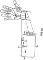
図1は、ユーザの手首に取り付けられた本発明の装置のある実施形態を示す図である。
図2Aは、図1に示す本発明の装置の実施形態の上面を示す。
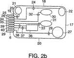
図2Bは、図1に示す本発明の装置の実施形態の底面を示し、電極構成を図示する。
図3は、本発明の装置のある実施形態のブロック図である。
図4は、本発明の装置のある実施形態の電気回路を示す。
図5は、本発明の装置によって誘発および測定された筋肉応答を示すグラフである。
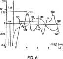
図6は、本発明の装置によって誘発および測定された筋肉応答信号の二次導関数を示すグラフである。
図7は、本発明の装置を用いて手根管症候群を発見するためのアルゴリズムのある実施形態を示すフローチャートである。
発明の詳細な説明
本発明の装置のある実施形態例、およびそのユーザの前腕8上への配置を図1に示す。本発明は、神経筋電極1および電子モニタ2の2つの主要部材で構成される。神経筋電極1は、刺激器および検出器の両方を含む。電子モニタ2は、コントローラおよびインジケータの両方を含む。本実施形態において、神経筋電極1および電子モニタ2は物理的に分離可能であり、両部材間の電気的接続は、神経筋電極1に関連付けられたコネクタ6と、電子モニタ2に関連付けられたコネクタスロット7とを物理的に接触させることによって確立される。別の実施形態においては、神経筋電極1および電子モニタ2は、物理的に分離できない単一のユニットを構成する。電子モニタ2は、診断プロセスを起動する手段を含む。図1に示す実施形態例を参照して、上記診断プロセスを開始するためにプッシュボタン3が設けられている。電子モニタ2は、診断プロセスの結果を表示または伝達するためのインジケータをも含む。図1に示す実施形態例を参照して、インジケータは、ディスプレイ4を含む。ディスプレイ4は、2つのマルチセグメント(multi−segment)発光ダイオード(LED)を含み、フィードバックおよび結果を与える。これらに限定はされないが、単一LEDおよび多色離散(multicolor discrete)LEDを含む他のインジケータを用いてもよい。例えば、スピーカのような他の種類のインジケータによって、聴覚信号を提供してもよい。電子モニタ2は、外部デバイスに接続および連絡するための連絡ポートをも含む。図1に示す実施形態例を参照して、連絡ポートは、ケーブルを挿入することができるジャック5を含む。そして、ケーブルの他端は、これらに限定はされないが、コンピュータおよび電話線を含む任意の数の異なるデバイスに接続される。
神経筋電極1は、電気的刺激を皮膚表面に送達し、皮膚表面からの生体電位(biopotentials)を検出し、そして、例えば、皮膚温度のようなさらなる生理学的パラメータおよび生物学的パラメータを測定する。図1に示すように、神経筋電極1は、手関節のしわ9の直ぐ近位側において前腕8の前部上に配置される。好適な実施形態においては、神経筋電極1の物理的寸法は、大人に見られる手首サイズの範囲に対して最適化された所定の寸法組から選択される。例えば、電極は、小、中、および大のサイズで構成され得る。神経筋電極1が、調節可能なバンドまたはストラップのような、例えば電極ハウジング内に入る所定の範囲にわたってその物理的な寸法を変える手段を含むさらなる実施形態が想定されている。バンドまたはストラップもまた、取外し可能であり得る。
神経筋電極1のある実施形態例を図2Aに示す。図2Aは、神経筋電極1の上面、およびそのユーザの手首上での適切な位置を示す。ある実施形態において、神経筋電極1の上面は、ユーザが神経筋電極1を適切に位置決めするのを助けるために、印刷された取扱説明46および/または他の視覚的指標45を含む。図2Bは、神経筋電極1の裏面を示す。この構成例では、図2Aに示すように、神経筋電極1が手関節のしわ9の直ぐ近位側に位置決めされたときに、母指球筋群51における筋活動を誘発および感知することが可能になる。2つの生体電気的変換部位(bioelectrical transduction sites)30および31(以下、刺激部位と呼ぶ)は、神経筋電極1の外側端部19および内側端部17のほぼ中間地点に位置決めされる。2つの刺激部位30および31は、遠位から近位方向へ向かう線に沿って構成され、一方の部位は神経筋電極1の遠位端部18の近傍にあり、もう一方の部位が神経筋電極1の近位端部20の近傍にある。
これらの刺激部位は、電子的信号を電気化学的信号に、そして電気化学的信号を電子的信号に変換する生体電気的信号変換手段の複数の規定された領域で構成される刺激電極で構成され得る。好適な実施形態において、これらの部位は、異なる材料の実質的に同面積の複数の層で構成される。第1の層は、神経筋電極1の底面に直接取り付けられ、好ましくは、銀の薄層で形成される。第2の層は、第1の層に取り付けられ、好ましくは、塩化銀塩で構成される。第3の層は、第2の層に取り付けられ、その露出表面がユーザの皮膚に接触する。第3の層は、好ましくは、例えば、塩化ナトリウムのような電解質ヒドロゲルで構成される。
図2Aに示すように、神経筋電極1を適切に位置決めすると、2つの刺激部位30および31は、正中神経50に重畳する。低振幅電流(例えば、典型的には10ミリアンペア未満)を2つの刺激部位30および31を通して流すことによって、神経50を刺激する。この電流は、外部コネクタ6上のコンタクト34および35に電気的に接続された外部供給源によって提供される。コンタクト34および35ならびに刺激部位30および31は、導電性/絶縁性手段32および33によって接続される。
2つの変換部位21および22(以下、検出部位と呼ぶ)は、遠位端部18近傍において、神経筋電極1の最外側端部19および内側端部17に位置決めされる。好適な実施形態において、検出部位21および22は、電子的信号を電気化学的信号に、そして電気化学的信号を電子的信号に変換する生体電気的信号変換手段の複数の規定された領域で構成される検出電極で構成される。好適な実施形態において、これらの部位は、刺激部位30および31と実質的に同様に構成される。
母指球筋51が収縮すると、筋電性電位が生じ、外側検出部位21の方が母指球筋51に比較的近いために、外側検出部位21と内側検出部位22の間に生体電気的電位差が生じる。この電位差は、外部コネクタ6上のコンタクト25および26間の小さな(例えば、典型的には0.5mV未満)電圧差として測定され得る。コンタクト25および26ならびに検出部位21および22は、導電性/絶縁性手段23および24によって接続される。電圧信号差の測定は、基準電位が利用可能であることによって高められるが、基準電位は、変換部位27(以下、基準部位または基準電極と呼ぶ)によって提供される。この部位は、神経筋電極1の内側端部17に沿って、その近位端部20に向かって位置決めされている。しかし、基準部位27の位置は、決定的なものではなく、本発明の作用にあまり影響しない。好適な実施形態において、基準部位27は、刺激部位30および31ならびに検出部位21および22と実質的に同様に構成される。導電性/絶縁性手段28によって基準部位27に接続される外部コネクタ6上のコンタクト29において、基準電位が利用可能になる。
神経筋電極1は、例えば、DS1820(Dallas Semiconductor,Dallas,TX)のような温度センサ36またはサーミスタを含む。センサ36の感温部は、ユーザの皮膚と直接、あるいは、効率的に熱を伝導する仲介材料を通して間接的に接触する。温度センサ36は、神経筋電極1の領域中の任意の利用可能な位置に配置され得る。温度センサ36の電力供給および電子モニタ2への温度情報の送信は、外部コネクタ6上の2つ以上のコンタクト39および40を通して行われる。コンタクト39および40ならびに温度センサ36は、導電性/絶縁性手段37および38によって接続される。
上記以外の変換部位およびセンサ構成ならびに配置も想定されており、本発明の範囲に入るものとみなされるべきである。そのような構成の1つとして、電子的多重化(electronic multiplexing)によって、刺激および検出の両方に1対の変換部位を用いたものが挙げられる。
電子モニタ2は、複数の機能を有する。モニタ2は、神経活動または筋活動によって生じる電位のような生体電気的電位の検出、増幅、処理および保存を行う。モニタ2はまた、神経または筋肉においてインパルスを生じるのに十分な大きさの複数段階の電流のような刺激を生じる。さらに、モニタ2は、ユーザ、および、例えば、パーソナルコンピュータのような外部機器と連絡する。最後に、電子モニタ2は、データを処理し、刺激付与の強度および持続時間を制御するコントローラを含む。
図1の電子モニタ2の例示的ブロック図を図3に示す。差動増幅器60は、入力端子間の電圧差を増幅し、その電圧差に比例する電圧を生じる。図1の電子モニタ2および神経筋電極1が、コネクタ6および7間の物理的接触によって接続される場合、図3の差動増幅器60は、検出部位21および22ならびに基準部位27に電気的に接続される。身体表面からの生体電気的信号は、典型的に、約5KΩ〜約50KΩの供給源インピーダンスを有し、大きな共通モード信号を含むので、差動増幅器60は、高い入力インピーダンス、良好な共通モード除去率および低いリーク電流を有する。これらの要件は、好ましくは、例えば、INA111(Burr−Brown,Tuscon,AZ)またはAD621(Analog Devices,Norwood,MA)のような計装用増幅器によって満たされる。
差動増幅器60は、アナログからデジタルへの変換およびその後の処理のために信号を用意する信号調整ユニット61に電気的に接続される。信号調整ユニット61は、好ましくは、DCオフセットを除去し、増幅、ローパスフィルタリングを行い、DCバイアスを生じる。信号調整ユニット61は、コントローラ63上のアナログ−デジタル変換器に電気的に接続される。
温度センサインターフェース電子部品62は、温度センサに電力供給し、温度に関連付けられた信号をコントローラ63が解釈できる形式に変換する。刺激器64は、コントローラ63からの信号によって決定されるインパルスの大きさおよび持続時間のいずいれか一方または両方を用いて、電気的インパルスを生じる。
刺激器64は、好ましくは、高い電圧(例えば、100ボルト)に充電されたキャパシタの放電をゲーティングする回路によって実施される。容量値(例えば、1μF)は、放電時間定数(例えば、数秒)が典型的なインパルス持続時間(例えば、1ミリ秒未満)よりも大幅に大きくなるように選択される。キャパシタにかかる電圧は、例えば、DC−DC変換器のような内部充電手段によって確立される。別の実施形態においては、この電圧は、外部充電手段によって確立される。後者の場合、刺激器64は、外部充電手段によって刺激器64を再充電する必要が生じる前に、有限数の電気的インパルスを生じることができる。
起動手段65は、プロセッサ63に電気的に接続され、好ましくは、1つ以上のプッシュボタンスイッチによって実施される。インジケータ66も、コントローラ63に電気的に接続され、好ましくは、単一またはマルチセグメントLEDによって実施される。最後に、外部インターフェース67は、コントローラ63に電気的に接続され、好ましくは、標準RS−232シリアルインターフェースとして実施される。コントローラ63は、アナログ−デジタル変換を行い、I/Oラインを感知および制御し、そして、取得データの処理、分析および保存を行う。コントローラ63は、好ましくは、単一の、一体型低コスト埋込みマイクロコントローラとして実施される。しかし、他の実施形態においては、コントローラ63は、例えば、マイクロプロセッサならびにアナログ−デジタル変換および他の必要な機能を行う外部構成要素のような複数の構成要素を用いて構成される。
図4は、図1の電子モニタ2のある実施形態の回路の模式図を示す。図4の回路例は、検出サブ回路、刺激サブ回路ならびに制御および処理サブ回路を含む。検出ステージは、U1増幅器、タイプINA111(Burr−Brown,Tuscon,AZ)計装用増幅器を利用している。増幅器U1の入力対100および101のそれぞれは、図2Bの検出器部位21および22の一方に電気的に接続される。さらに、増幅器U1は、図2Bの基準部位27への電気的接続を通して基準電位を受け取る基準ピン102を有する。U1は、モノリシック計装用増幅器であり、好ましくは10の倍数であるその増幅ゲインを確立するために、抵抗R7という1つの外部構成要素を必要とする。増幅器U1は、+Vc110および−Vc111(例えば、6ボルト)、ならびにグラウンド112を提供する画面対称電源によって電力供給される。好適な実施形態において、+Vc110、−Vc111およびグラウンド112は、図4に示すように直列に接続された2つのバッテリB1およびB2によって提供される。増幅器U1の出力は、キャパシタC1および抵抗R1によって形成されるハイパスフィルタを通して、オペアンプU2aによって形成される非反転増幅器の入力に接続される。ハイパスフィルタは、増幅器U1の出力のあらゆるDCオフセットを除去する。好適な実施形態において、キャパシタC1および抵抗R1は、約2Hzのハイパスコーナー周波数が得られるように選択される。非反転増幅器のゲインは、抵抗R2およびR10によって確立され、好ましくは、500のゲインに設定される。第1のオペアンプU2aの出力は、抵抗R3およびキャパシタC2によって形成されるローパスフィルタによって、第2のオペアンプU2bの入力に接続される。このローパスフィルタは、信号から高周波ノイズを除去する。好適な実施形態において、抵抗R3およびキャパシタC2は、約3KHzのローパスコーナー周波数が得られるように選択される。第2のオペアンプU2bは、単純にインピーダンスバッファとして構成される。増幅器U2bの出力は、キャパシタC4ならびに抵抗R8およびR9で構成されるDCバイアス回路によって、マイクロコントローラU4上のアナログ−デジタル変換ピンに接続される。DCバイアス回路の目的は、全ての信号がグラウンド112から+Vc110まで変化することを確実にするためである。なぜなら、マイクロコントローラU4のアナログ−デジタル変換電子部品は、正の電圧に対してしか動作しないからである。検出ステージは、マイクロコントローラU4上のI/Oピンに接続された、図2Bの「1配線(one−wire)」温度センサ36のインターフェースをとるための組み合わせ連絡および電力ライン116をも有する。
この装置の刺激サブ回路は、高容量(例えば、1μF以上)かつ高電圧(例えば、100ボルトより大きい)キャパシタであるエネルギー保存キャパシタC3を利用している。この装置のある実施形態において、キャパシタC3は、外部充電手段105によって100ボルトを越える値に充電される。キャパシタC3の充電は、充電期間の間一時的にキャパシタC3端子109および108に電気的に接続される端子107および106間に電流を流す充電手段105によって行われる。キャパシタC3の充電が終わると、充電手段105は取り外される。神経および筋肉の電気的刺激は、刺激部位30および31に電気的に接続されるリード103および104を通して放電キャパシタC3によって行われる。刺激持続期間の制御は、マイクロコントローラU4からのデジタル信号に従って放電をゲーティングするパワーMOSFETトランジスタQ1によって行われる。抵抗R4は、それを通って流れる電流を制限することによって、トランジスタQ1を保護する。
この装置の制御および処理ステージは、好ましくは、タイプPIC12C71(MicroChip,Chandler,AZ)マイクロコントローラであるマイクロコントローラU4を利用している。U4は、処理および保存能力、アナログ−デジタル変換および入力/出力制御を提供する。上述の検出サブ回路および刺激サブ回路への接続に加えて、マイクロコントローラU4は、I/Oピンに接続されるスイッチS1の押下を検出するとともに、これもI/Oピンに接続される発光ダイオードLED1を制御する。抵抗R6は、スイッチS1が押下されたときにI/Oピンに流入する電流を制限し、抵抗R5は、発光ダイオードLED1を流れる電流を制限する。さらに、外部デバイスへのシリアル連絡115は、残りの利用可能なI/Oピンによって提供される。制御および処理アルゴリズムは、マイクロコントローラU4内に保存されており、電力投入時に自動的に実行される。上記の処理を行うために他の電子回路を用いてもよく、それも、本発明の範囲に入るものとみなされる。上述の機能を果たす電子回路を設計する方法は、当業者には公知である。
本発明の主要な目的の1つは、CTSの検出システムとして機能することである。従来のCTS検出は、誘発された筋肉応答の特定の特徴(典型的には、遠位モータ潜伏期(distal motor latency)(DML))の分析に基づいている。DMLは、手関節のしわ9の直ぐ近位側の正中神経50を刺激してから、手根管を通って神経伝導されたインパルスが母指球筋群51に到達するまでの時間のずれを表す。最も一般的で一貫したCTSの指標は、DMLの増加である。DMLの一義的な定義はないが、DMLは、概ね、刺激の開始時点(即ち、時間=0)から筋肉応答に対して一貫した特徴が発生するまでに経過した時間の長さとして定義される。
本発明の装置を用いて誘発および取得される典型的な筋肉応答120を図5に示す。縦軸目盛121は、検出部位21および22間で測定されたミリボルト単位の筋肉応答の振幅を示す。横軸目盛122は、刺激パルスの発生からの経過時間を示す(即ち、刺激の発生は、時間=0)。最初の2ミリ秒に生じている大きな過渡信号123は、刺激に関連するアーチファクトを表すものであり、母指球筋51における活動とは無関係である。誘発された筋肉応答120は、発生までの時間124、ピークまでの時間125、ピーク振幅126、ピークトゥピーク振幅127およびピークトゥピーク幅128を含む多数のパラメータによって特徴付けられ得る。但し、パラメータは、これらに限定されない。図5の例示的な例では、発生までの時間124は約3.7ミリ秒であり、ピークまでの時間125は約5.8ミリ秒である。
母指球筋51応答が、その生理学的発生部位から有意に離れた場所で検出されるので、介在する組織がローパスフィルタとして機能する。結果的に、母指球筋51の直上でとられた測定値と比べて、検出される波形には、振幅減衰および時間的広がりがある。振幅が減少する結果、検出される筋肉応答120の信号対ノイズ比が低減する。時間的広がりは、応答120の急峻な特性をぼやかす。これらの2つのローパス関連効果が合わさって、特に様々なノイズ源(例えば、腕の筋肉の単収縮(muscle twitch)によって生じるような外部筋活動)が存在する場合に、発生までの時間124またはピークまでの時間125のような筋肉応答特徴の一貫した正確な特定が、困難で非常に不定なものとなる。
好適な実施形態において、筋肉応答120の分析は、その特性を決定する前に予備処理することにより、大幅に向上する。このような処理ステップの1つは、図6に示すように筋肉応答120の二次導関数をとることである。この予備処理ステップが有利であることは、二次導関数130(実線)が筋肉応答120の発生124の近傍にピーク131を有することから明らかである。結果的に、単に、このピーク131の存在を検出するだけで、潜伏期推定値(latency estimate)133を正確に一貫して得られるようになる。対照的に、発生までの時間124を筋肉応答120から直接推定しようとすると、複数の個人の間で有意にばらつき得る任意電圧閾値を確立する必要が生じる。
好適な実施形態において、図6の二次導関数130における急峻なピーク131は、例えば、所定の標準偏差を有する正規化ガウス波形を用いて筋肉応答120を畳み込むなどの方法によって筋肉応答120を先ず平滑化することによって得られる。その後で、筋肉応答120中の各データ点についての瞬間的傾き(instantaneous slope)を推定することによって、一次導関数を計算する。その後、今計算したばかりの一次導関数中の各データ点についての瞬間的傾きを推定することによって、二次導関数を計算する。ダイナミックメモリのリソースを節約するために、一次および二次導関数130を、筋肉応答120の小さな区間毎に順次計算して、その値が二次導関数130のピーク131の存在を示さない場合に値を破棄することが可能である。
二次導関数130のピーク131が特定された後、ある規定された時間窓136内における最大の正ピークを選択する。この時間窓136は、2つの時間限界値134および135の間に生じるように規定される。好適な実施形態において、時間下限値134は、所定の値であり、刺激に関連するアーチファクト123が、筋肉120によって誘発された実際の信号の振幅よりも有意に低い振幅まで減衰するのにかかる時間の長さを反映した値である。時間下限値134は、好ましくは、約2.5ミリ秒である。しかし、他の時間下限値を用いてもよい。さらに、刺激に関連するアーチファクト123の振幅減衰を分析することによって、時間下限値134を動的に確立することも可能である。時間上限値135は、動的に決定される。好適な実施形態において、時間上限値135は、誘発された筋肉応答120の一次導関数が正である時間を反映するように設定される。換言すれば、時間上限値135は、誘発された筋肉応答120が増加している期間を反映した値である。このようにして時間上限値135を確立すれば、応答の後半部分で生じる応答の二次導関数130の大きなピーク132は無視されるので、大きなピーク132によって、潜伏期推定値133が不正確になることがない。
本発明の好適な実施形態において、図7に、本発明の装置を完全に自動化して用いてCTSを検出するためのアルゴリズム例を示す。アルゴリズムは、例えば、STARTスイッチS1の押下のような起動手段65を活性化することによって、処理ステップ140から始まる。起動手段が活性化されると、アルゴリズムは、処理ステップ142へと進む。そうでなければ、処理ステップ140は、起動手段が活性化されるまで続けて実行される。処理ステップ142において、電気的刺激が全く無い状態で、ノイズの平方自乗平均(RMS)値を得て、これを所定の閾値nmaxと比較する。ノイズRMSが、nmax未満である場合、アルゴリズムは、処理ステップ146へと進む。しかし、ノイズRMSが、nmaxより大きい場合、アルゴリズムは処理ステップ144へと進み、インジケータ66を用いて、ノイズレベルに関する問題をユーザに示す。その後、アルゴリズムは、処理ステップ140に戻り、STARTスイッチS1の再起動を待つ。
処理ステップ146において、CTSの診断に用いる刺激の大きさを決定する。好適なプロセスにおいては、このパラメータは、ユーザが関与することなく自動的に決定される。これは、誘発された筋肉応答120が1つ以上の所定の基準を満たすまで、所定の増加幅(例えば、25マイクロ秒)で刺激持続時間を徐々に増加させることによって行われる。一例としては、誘発された筋肉応答120の一次導関数のピークが所定の閾値(例えば、0.1mV/ms)を上回るまで刺激持続時間を増加させる。適切な刺激持続時間が得られると、アルゴリズムは、処理ステップ148から処理ステップ152へと進む。適切な刺激の大きさが得られない場合(即ち、所定の閾値を上回らない場合)、アルゴリズムは処理ステップ150に進み、インジケータ66を用いて、刺激の大きさの決定に関する問題をユーザに示す。その後、アルゴリズムは、処理ステップ140に戻り、STARTスイッチの再起動を待つ。
適切な刺激の大きさが決定されると、アルゴリズムは、処理ステップ152に進む。このステップでは、正中神経50を、所定のレート(例えば、2Hz)で、所定の持続時間(例えば、2秒)の間刺激する。各母指球筋応答120を上記のように分析し、これにより、筋肉応答120の二次導関数130の大きなピーク133として遠位モータ潜伏期(DML)を推定する。さらに、複数のDML推定値を組み合わせて、平均DML(m)およびこの平均値についての標準偏差(s)を得る。その後、アルゴリズムは、処理ステップ153に進み、皮膚温度のばらつきについてmおよびsを調節する。具体的には、下記の2つの調節式を適用する。
(A)mcorrected=muncorrected+k1T+k2
(B)Scorrected=Suncorrected+k1T+k2
補正された平均DML(mcorrected)および標準偏差(Scorrected)は、室温(即ち、25℃または298゜K)における予想値を表す。温度センサ36によって測定される皮膚温度を変数Tとして表す。定数k1およびk2の値は、温度較正プロセスによって決定される。このプロセスにおいて、平均DMLの複数の測定値が、本発明が通常使用される予想温度範囲(例えば、25℃から40℃)にわたる様々な温度において得られる。その後、それらの温度と平均DML測定値との間で線形回帰を行う。定数k1およびk2は、回帰係数から直接決定される。
その後、アルゴリズムは、処理ステップ154に進み、DML測定値の標準偏差sを所定の閾値sminと比較する。sがsmin以上である場合、処理ステップ156が実行される。処理ステップ156では、mおよびsが決定された回数を評価する。これらの値が1回しか計算されていない場合、アルゴリズムは、処理ステップ146に戻り、適切な刺激レベルおよびその後の全ての処理の決定が繰り返される。しかし、mおよびsが2回決定されている場合、処理ステップ158が実行され、インジケータ66を通してユーザに診断エラーが示される。その後、アルゴリズムは、処理ステップ140に戻り、STARTスイッチS1の再起動を待つ。
処理ステップ154において、sがsmin未満であると判定された場合、アルゴリズムは、処理ステップ160に進む。このステップにおいては、DML推定値の平均値mを所定の潜伏期閾値tnormalと比較する。mがtnormal未満である場合、アルゴリズムは、処理ステップ162に進み、正常(即ち、ユーザはCTSに罹っていない)の検査結果がインジケータ66を通してユーザに示される。その後、アルゴリズムは、処理ステップ140に戻り、STARTスイッチS1の再起動を待つ。mがtnormal以上である場合、アルゴリズムは、処理ステップ164に進み、平均遠位モータ潜伏期mを第2の所定の潜伏期値tCTSと比較する。mがtCTSより大きい場合、アルゴリズムは、処理ステップ166に進み、異常(即ち、ユーザはCTSに罹っている)の検査結果がインジケータ66を通してユーザに示される。その後、アルゴリズムは、処理ステップ140に戻り、STARTスイッチS1の再起動を待つ。
上記2つの不等式がいずれも真でない場合、アルゴリズムは、処理ステップ168に進む。このステップにおいては、所定の時間間隔(例えば、3ミリ秒)だけ間隔を空けた電気的刺激対によって正中神経150を刺激する。誘発された筋肉応答120のそれぞれについて、第1および第2の刺激から推定されるDML間の差を決定する。さらに、複数のDML差推定値を組み合わせて、平均DML差(m')およびこの平均値についての標準偏差(s')を求める。これらの2つのパラメータを測定した後、アルゴリズムは、処理ステップ170に進み、平均DML差m'を所定の閾値tshiftと比較する。m'がtshiftよりも大きい場合、処理ステップ166が実行され、上記のように異常の検査結果をユーザに示す。この不等式が成り立たない場合、処理ステップ172において、不明の検査結果をユーザに示す。その後、アルゴリズムは、処理ステップ140に戻り、STARTスイッチS1の起動を待つ。
上記のアルゴリズムは例示に過ぎない。本発明の装置を用いてCTSを検出する他のアルゴリズムが開発され得る。例えば、この診断アルゴリズムに、DML以外のパラメータを用いてもよい。パラメータ例としては、例えば、振幅および幅のような誘発された筋肉応答120の波形特徴が含まれる。さらに別のパラメータ例としては、例えば、導関数、フーリエ変換および統計学的分析(例えば、主成分分析)から導出される他のパラメータのような、誘発された筋肉応答120の波形特徴を処理したものが含まれる。さらに、異なる刺激レベルにおける上記パラメータの任意のものを比較することにより、さらに別のパラメータが得られる。
上記のアルゴリズム例はCTSの検出に関するが、本発明の装置は、他の形態の神経疾患の発見および神経筋遮断の評価にも使用できる。例えば、麻酔下の患者における神経筋遮断の度合いを評価するために広く利用されている4連(TOF)プロトコルは、本発明の装置を用いて容易に実施される。具体的には、所定の数(通常、4つ)の筋肉応答120を所定のレート(例えば、2Hz)で誘発して、各応答の振幅126を決定する。その後、誘発される最後の複数の筋肉応答の振幅比を、誘発される最初の複数の筋肉応答の振幅で割る。この比は、神経筋遮断の高感度な指標として認識されている。
ここに開示される発明は、神経筋生理機能のモニタリングのための新規なアプローチを提供する。多くの異なる神経筋生理機能パラメータの実質的に自動化された効率的な測定のための装置および方法が記載される。これらの指標を用いて、手根管症候群(CTS)および他の末梢神経疾患を発見したり、病理学的、薬理学的および化学的手段によって引き起こされる神経筋遮断をモニタすることが可能である。本発明は、以下のような顕著な利点を有する。即ち、手首を通る神経伝導を測定するための従来技術とは異なり、ここに開示される発明は、手首の直ぐ近位側(即ち、手関節のしわ)に配置される一体型の単一神経筋電極を提供する。これはよく知られた解剖学的位置であるので、ほとんどの大人は、この配置動作を迅速かつ容易に行うことができる。従来の装置および方法とは異なり、ここに開示される発明では、複数組の電極を手首の両側に配置しなくてもよい。複数組の電極を手首の両側に配置することは、非専門家にとっては、困難かつ誤差の出やすい手順である。一体型の神経筋電極は、低コストな使い捨ての部品として製造できることにより、ここに開示される発明のまた別の利点が生じる。結果的に、本装置のユーザ間での相互感染(cross−contamination)の可能性は、大幅に低減される。さらに、低いコストおよび使い易さにより、CTSのような神経筋疾患のモニタリングがより頻繁に行われるようになるであろう。これにより、疾患の早期発見および定期的な追跡検査という潜在的な利点が提供される。本発明の別の利点は、神経筋信号を誘発、検出および処理するプロセスが、完全に自動化された方法で行われ、装置のユーザあるいは熟練した人員が関与する必要がないことである。本発明のさらなる利点は、正確な診断アセスメントと一貫した最小かつ最少の電気的刺激が使用されることである。結果的に、ユーザの不快感は、最小限に抑えられるか、ほとんどの場合完全になくなる。
本発明を特定の好適な実施形態例に関連して記載したが、当業者であれば、本発明がそれらに限定されないこと、ならびに、下記の請求の範囲に記載された発明の範囲内で、これらの好適な実施形態に対して多くの追加、削除および改変を行うことが可能であることが容易に理解かつ認識されるであろう。従って、本発明の範囲は、添付の請求の範囲によってのみ限定される。Field of Invention
The present invention relates to an apparatus and method for assessment of neuromuscular function. More specifically, the present invention relates to an apparatus and method for diagnosing end-of-life nerves and muscle conditions based on assessment of neuromuscular function.
Background of the Invention
In many clinical and non-clinical situations, a quick, reliable, low-cost assessment of neuromuscular function is required. In order to monitor neuromuscular function in surgical and intensive care situations, a reliable and automated device is required. For example, muscle relaxants significantly improve surgical procedures and post-operative treatments by adjusting the effectiveness of nerve to muscle coupling through a process called neuromuscular blockage. To do. However, muscle relaxants are difficult to use safely and efficiently because there are wide variations in patient responses and the responses cannot be predicted. In other situations, it is advantageous to have an easy-to-use and reliable indicator in assessing the possibility of contamination exposure situations due to chemicals. These substances destroy neuromuscular function, effectively cause neuromuscular blockade, and endanger soldiers and the general public.
However, the most common causes of neuromuscular destruction are associated with peripheral nerve and muscle conditions. For example, neuromuscular diseases such as carpal tunnel syndrome (CTS) are very common and well known. Despite the great impact on individuals and health systems, the discovery and monitoring of such neuromuscular conditions is still expensive, complex, and very underutilized.
CTS is one of the most common forms of neuromuscular disease. The disease is thought to result from compression of the median nerve through the wrist. In many cases, CTS causes hand discomfort and numbness, and in severe cases, the hand becomes almost unusable. Very repetitive wrist movements and medical conditions such as diabetes, rheumatoid arthritis, thyroid disease and pregnancy are considered factors contributing to the development of CTS. In 1995, the National Center for Health Statistics stated that there were 1.89 million cases of CTS in the United States alone.
Early detection and subsequent action are required to effectively prevent CTS. Unfortunately, the current state of CTS diagnosis is not very good. Even experienced doctors find it difficult to diagnose CTS and grade its severity by its symptoms alone. The only objective CTS discovery method is to measure the transmission of neural signals across the wrist. The royal road is a formal nerve conduction test by a clinical neurologist, but this clinical procedure has several significant drawbacks. First, this procedure is a time consuming process that requires the service of a medical professional such as a neurologist. Second, this procedure is very expensive (eg, $ 600- $ 1000). Furthermore, this procedure is not available in environments where early detection can significantly reduce the rate of CTS, such as workplaces where a large number of CTS causes exist. Because of these shortcomings, formal electrophysiological evaluation of suspected cases of CTS has not been done extensively, reducing the likelihood of early detection and prevention.
In the prior art, attempts have been made to simplify the assessment of neuromuscular function, such as CTS diagnosis, or to make such diagnostic measurements available to non-experts. Rosier (US Pat. No. 4,807,643) describes a portable device that measures the nerve conduction velocity of a patient. However, this instrument has several very significant drawbacks. First, this instrument requires two sets of electrodes (one set at the stimulation site and the other at the detection site). As a result, the correct application of the device must be ensured by a skilled operator who has considerable knowledge about nerve and muscle anatomy. Improper placement of one or both electrode sets can result in significant diagnostic errors. Secondly, the Rosier device has the disadvantage of not being automated. Specifically, the device user must establish the magnitude of the electrical stimulus and the response detection threshold. These parameters are difficult to determine a priori and establishing them quickly and accurately requires familiarity with both neurophysiology and detailed electrical operation of the device.
Spitz et al. (US Pat. No. 5,215,100) and Lemmen (US Pat. No. 5,327,902) also sought to improve upon the prior art. Specifically, Spitz et al. And Lemmen proposed a system that measures nerve conduction parameters between the arm or forearm and hand, as required for the diagnosis of CTS. However, in either case, an electrode support structure or fixture that substantially fixes the position where the stimulation electrode contacts the arm and the position where the detection electrode contacts the hand is proposed. In addition, these systems have several significant drawbacks. First, both systems are relatively large and bulky because they include support fixtures for adult arms and hands. This greatly limits the portability of these systems and increases their cost. Second, these devices still require a highly skilled operator who can properly adjust the device so that the electrodes are in contact with the appropriate anatomical sites of the arms and hands. A third drawback of both systems is that they still require multiple operator decisions regarding stimulation and detection parameters. Finally, these prior art systems have the disadvantage of not performing diagnostic procedures automatically or presenting the results in a simple and easily interpretable form.
Accordingly, there remains a need for an apparatus and method for assessing neuromuscular function that is less time consuming, less expensive, and more widely available (ie, more portable and easy to use). Such devices and methods are needed to make the early detection and prevention of neuromuscular pathologies such as CTS more prevalent. The present invention addresses these needs.
Summary of the Invention
In accordance with the present invention, an apparatus and method for the assessment of neuromuscular function that is substantially automated, quick and efficient without the need for skilled personnel is provided. Assessment of neuromuscular function is performed by stimulating a nerve and then measuring the response of the muscle innervated by that nerve. Muscle response is measured by measuring the myoelectric potential generated by the muscle in response to a stimulus. One indicator of the physiological state of the nerve is provided by the delay between applying the stimulus and detecting the muscle response. If a nerve is damaged, the transmission of signals through the nerve to the muscle, and hence the detection of the muscle response, is slow compared to a healthy nerve. Thus, an abnormal delay between applying a stimulus and detecting a muscle response indicates neuromuscular dysfunction. In the case of the device and method of the present invention, both stimulation and response detection are performed entirely at a position just proximal to the individual's wrist (ie, the wrist crease). This anatomical location is a well-known location that is easy to locate, thus ensuring correct placement of the device at the assessment site by a non-expert while maintaining the accuracy of the results. This ease of use increases the availability and diagnosis of conditions such as carpal tunnel syndrome (CTS).
The apparatus and method of the present invention assesses neuromuscular function in an individual's arm using a stimulator that provides stimulation to nerves passing through the individual's wrist. The stimulator is adjusted to provide stimulation to the nerve at a location proximal to the individual's wrist. The stimulus may be, for example, an electrical stimulus or a magnetic stimulus. Other types of stimuli may be used. A detector tuned to detect the myoelectric potential generated by the muscle in response to this stimulus also detects the muscle's response to the stimulus at a site proximal to the individual's wrist. The controller then evaluates the physiological function of the nerve, for example, by determining the delay between applying the stimulus and detecting the myoelectric potential. This delay is then correlated with the presence or absence of a neuromuscular condition such as carpal tunnel syndrome (CTS).
In a preferred embodiment, both the stimulator and the detector are in electrical communication with electrodes that are adjusted to be placed proximal to the wrist of the individual's arm. The controller may also be in electrical communication with a reference electrode and a temperature sensor. The apparatus of the present invention is for establishing communication between the apparatus and an external device such as a personal computer. A communication port may further be provided.
In another embodiment, the apparatus of the present invention may further comprise an indicator. The indicator is in electrical communication with the controller and is adjusted to indicate the physiological function evaluated by the controller in response to the applied stimulus and the detected myoelectric potential. The indicator may comprise a light emitting diode. In a particularly preferred embodiment, the indicator is adjusted to indicate the presence or absence of CTS.
The device of the present invention may further be implemented as an electrode configuration housed in an electrode housing that is removably secured to an individual's wrist. The electrode housing includes a mounting mechanism, such as a non-irritating adhesive material, for fixation to an individual's arm and can be disposable. Preferably, the electrode housing has a connector for electrical communication with the device comprising the stimulator, detector and processor as described above.
The electrode housing includes a stimulation electrode and a detection electrode. The stimulation and detection electrodes are sized and shaped within the housing such that when the housing is secured to the individual's wrist, it contacts the front of the individual's arm on the proximal side of the wrist. Yes. The electrode configuration may further include a temperature sensor and / or a reference electrode.
In a preferred embodiment, the electrode configuration comprises a second stimulation electrode and a second detection electrode. The two stimulation electrodes are positioned substantially in the center of the electrode housing and are configured to be positioned at opposite ends of the housing. The two stimulation electrodes preferably have one stimulation electrode located just proximal to the wrist and the other more proximal to the wrist when the housing is placed on the front of the user's arm. It is configured to The two detection electrodes are also located at opposite ends of the housing. However, when these detection electrodes are arranged on the front part of the user's arm, they are positioned so that one detection electrode is positioned inside the wrist and the other detection electrode is positioned outside the wrist.
The method of the present invention relates to the assessment of neuromuscular function using the device of the present invention. A device such as that described above is used to stimulate the nerves that pass through the individual's wrist on the proximal side of the wrist. The muscle innervated by the nerve produces a myoelectric potential in response. This myoelectric potential is detected proximal to the individual's wrist. The detected response is processed by determining the first derivative of the myoelectric potential, and preferably the second derivative of the myoelectric potential. In a preferred embodiment, these derivatives are used to determine the appropriate stimulus level and to determine the delay between applying the stimulus and detecting the associated response. In another embodiment, further measurements regarding this delay are made. For example, a change in delay induced by at least two stimulations is determined. The delay calculated from any of these measurements and the parameters associated therewith are then correlated to the physiological function of the nerve and muscle.
In a preferred embodiment, the device of the present invention is used to indicate the presence or absence of CTS. For example, a plurality of stimuli are applied to nerves passing through the carpal tunnel such as the median nerve. These stimuli may be delivered one at a time at a predetermined rate, or in pairs at a predetermined rate. When delivered in pairs, each stimulus application is divided into predetermined time intervals.
In response to these stimuli, muscles innervated by the stimulated nerve produce multiple myoelectric potentials. Each myoelectric potential occurs in response to a respective stimulus application. The application of each of these stimuli and the delay of the detected response is determined. For multiple delays, statistics such as mean and standard deviation are calculated. Based on these statistics, the probability value that the individual has CTS is calculated. Thereafter, an index indicating the presence or absence of CTS is given based on this value.
In another embodiment of the invention, the method may include further steps. For example, in certain embodiments of the invention, the method calculates the difference between delays measured in response to two stimuli delivered at short time intervals and, as described above, these delay differences. And determining the probability value that the individual has CTS based on the calculated statistic. In another embodiment, the level of noise is measured before stimulating the nerve. In yet another embodiment, the mean value and standard deviation of the delay are adjusted for skin temperature.
In this manner, an apparatus and method for the above substantially automated and accurate assessment of neuromuscular function is provided. The apparatus and method of the present invention allows for easier discovery of neuromuscular conditions such as CTS, for example, at a lower cost, without the need for skilled professionals.
The present invention will be further understood in light of the following drawings, description and claims.
Description of drawings
FIG. 1 shows an embodiment of the device of the present invention attached to a user's wrist.
FIG. 2A shows a top view of the embodiment of the apparatus of the invention shown in FIG.
FIG. 2B shows the bottom of the embodiment of the device of the invention shown in FIG. 1 and illustrates the electrode configuration.
FIG. 3 is a block diagram of an embodiment of the apparatus of the present invention.
FIG. 4 shows the electrical circuit of an embodiment of the device of the present invention.
FIG. 5 is a graph showing the muscle response elicited and measured by the device of the present invention.
FIG. 6 is a graph showing the second derivative of the muscle response signal induced and measured by the device of the present invention.
FIG. 7 is a flowchart illustrating one embodiment of an algorithm for finding carpal tunnel syndrome using the apparatus of the present invention.
Detailed Description of the Invention
An example embodiment of the device of the present invention and its placement on the user's
The
An example embodiment of the
These stimulation sites consist of stimulation electrodes composed of a plurality of defined areas of bioelectric signal conversion means that convert electronic signals into electrochemical signals and electrochemical signals into electronic signals. obtain. In a preferred embodiment, these sites are comprised of multiple layers of substantially the same area of different materials. The first layer is attached directly to the bottom surface of the
As shown in FIG. 2A, when the
Two
When the
The
Other conversion sites and sensor configurations and arrangements are envisioned and should be considered within the scope of the present invention. One such configuration is one that uses a pair of conversion sites for both stimulation and detection by electronic multiplexing.
The
An exemplary block diagram of the
The
The temperature
The
The activation means 65 is electrically connected to the processor 63 and is preferably implemented by one or more push button switches.
FIG. 4 shows a schematic diagram of a circuit of an embodiment of the
The stimulation subcircuit of this device utilizes an energy storage capacitor C3 that is a high capacitance (eg, 1 μF or greater) and high voltage (eg, greater than 100 volts) capacitor. In one embodiment of this device, capacitor C3 is charged to a value greater than 100 volts by external charging means 105. Charging of the capacitor C3 is performed by charging
The control and processing stage of this device preferably utilizes a microcontroller U4 which is a type PIC12C71 (MicroChip, Chandler, AZ) microcontroller. U4 provides processing and storage capabilities, analog-to-digital conversion and input / output control. In addition to the connection to the detection and stimulation subcircuits described above, the microcontroller U4 detects the pressing of the switch S1 connected to the I / O pin and also a light emitting diode connected to the I / O pin Control LED1. The resistor R6 limits the current flowing into the I / O pin when the switch S1 is pressed, and the resistor R5 limits the current flowing through the light emitting diode LED1. In addition, serial communication 115 to external devices is provided by the remaining available I / O pins. Control and processing algorithms are stored in the microcontroller U4 and are automatically executed upon power up. Other electronic circuits may be used to perform the above processing and are considered to be within the scope of the present invention. Methods for designing electronic circuits that perform the functions described above are known to those skilled in the art.
One of the main objectives of the present invention is to function as a CTS detection system. Conventional CTS detection is based on analysis of specific characteristics of the evoked muscle response (typically distal motor latency (DML)). DML represents the time lag from the stimulation of the
A
Since the
In a preferred embodiment, the analysis of
In a preferred embodiment, the
After the
In a preferred embodiment of the present invention, FIG. 7 shows an example algorithm for detecting CTS using a fully automated apparatus of the present invention. The algorithm begins at
In
Once the appropriate stimulus magnitude is determined, the algorithm proceeds to process
(A) mcorrected= Muncorrected+ K1T + k2
(B) Scorrected= Suncorrected+ K1T + k2
Corrected average DML (mcorrected) And standard deviation (Scorrected) Represents the expected value at room temperature (
Thereafter, the algorithm proceeds to process
In
If neither of the two inequalities is true, the algorithm proceeds to process
The above algorithm is only exemplary. Other algorithms for detecting CTS using the apparatus of the present invention can be developed. For example, parameters other than DML may be used for this diagnostic algorithm. Examples of parameters include the waveform characteristics of the evoked
Although the above example algorithm relates to the detection of CTS, the device of the invention can also be used to detect other forms of neurological disease and assess neuromuscular blockade. For example, the widely used Quadruple (TOF) protocol for assessing the degree of neuromuscular blockade in anesthetized patients is easily implemented using the device of the present invention. Specifically, a predetermined number (usually four)
The invention disclosed herein provides a novel approach for monitoring neuromuscular physiology. Devices and methods for substantially automated and efficient measurement of many different neuromuscular physiology parameters are described. These indicators can be used to discover carpal tunnel syndrome (CTS) and other peripheral neurological diseases and to monitor neuromuscular blockade caused by pathological, pharmacological and chemical means . The present invention has the following significant advantages. That is, unlike the prior art for measuring nerve conduction through the wrist, the invention disclosed herein is an integrated single nerve that is placed just proximal to the wrist (ie, the wrist crease). A muscle electrode is provided. Since this is a well-known anatomical location, most adults can perform this placement operation quickly and easily. Unlike conventional devices and methods, the invention disclosed herein does not require multiple sets of electrodes on either side of the wrist. Placing multiple sets of electrodes on both sides of the wrist is a difficult and error-prone procedure for non-experts. The integral neuromuscular electrode can be manufactured as a low-cost, disposable part, resulting in yet another advantage of the invention disclosed herein. As a result, the possibility of cross-contamination between users of the device is greatly reduced. Furthermore, the low cost and ease of use will make monitoring of neuromuscular diseases like CTS more frequent. This provides the potential benefits of early disease detection and periodic follow-up. Another advantage of the present invention is that the process of inducing, detecting and processing neuromuscular signals is performed in a fully automated manner and does not require the involvement of a device user or skilled personnel. A further advantage of the present invention is that minimal and minimal electrical stimulation consistent with accurate diagnostic assessment is used. As a result, user discomfort is minimized or almost completely eliminated.
While the invention has been described in connection with specific preferred embodiments, those skilled in the art will recognize that the invention is not limited thereto and, within the scope of the invention as set forth in the claims below, It will be readily understood and appreciated that many additions, deletions and modifications can be made to these preferred embodiments. Accordingly, the scope of the invention is limited only by the appended claims.
Claims (35)
Translated fromJapanese(a)刺激を生成し、該刺激を個人の手首の近位側に付与する刺激器であって、該刺激の付与は該手首を通る神経を刺激する、刺激器と、
(b)個人の手首の近位側において、筋電性電位を検出する検出器であって、該筋電性電位は、該刺激に応答して該個人の手の筋肉によって生じるものであり、該筋肉は該神経と連絡状態にある、検出器と、
(c)該刺激および該筋電性電位に応答して、生理学的機能を評価するコントローラと、
を備えた装置。A device for assessing physiological functions in an individual's arm and hand,
(A) a stimulator that generates a stimulus and applies the stimulus to a proximal side of an individual's wrist, the application of the stimulus stimulating a nerve passing through the wrist;
(B) a detector for detecting a myoelectric potential proximal to the individual's wrist, the myoelectric potential being generated by the muscle of the individual's hand in response to the stimulus; The muscle is in communication with the nerve, a detector;
(C) a controller that evaluates physiological function in response to the stimulus and the myoelectric potential;
With a device.
(a)個人の手首の近位側において刺激を付与する手段であって、該刺激の付与は該手首を通る神経を刺激する、手段と、
(b)個人の手首の近位側において、筋電性電位を検出する手段であって、該筋電性電位は、該刺激に応答して該個人の手の筋肉によって生じるものであり、該筋肉は該神経と連絡状態にある、手段と、
(c)該刺激および該筋電性電位を処理する手段と、
(d)該処理された結果を該神経および該筋肉の生理学的機能に相関させる手段と、
を包含する、装置。A device for assessing physiological functions in an individual's arm and hand,
(A) means for applying a stimulus on the proximal side of an individual's wrist, the application of the stimulus stimulating a nerve passing through the wrist;
(B) means for detecting a myoelectric potential proximal to the wrist of the individual, the myoelectric potential being generated by the muscle of the individual's hand in response to the stimulus, Muscle is in communication with the nerve, means;
(C) means for processing the stimulus and the myoelectric potential;
(D) means for correlating the processed results with physiological functions of the nerves and muscles;
Including the device.
(a)該個人の手首の近位側において刺激を付与するように適合された刺激電極と、
(b)該刺激電極に関して固定の関係にあり、該刺激に応答して、該個人の該手の筋肉によって生じる筋電性電位を該手首の近位側において検出するように適合された検出電極と、
を備え、
生理学的機能は、該刺激および該筋電性電位に応答して評価され、該刺激電極および該電極は、該手首の近位側にある該個人の該腕の前部上に位置決めされるように大きさおよび形状が決められている、
電極構成。An electrode configuration for assessing physiological functions in an individual's arm and hand,
(A) a stimulation electrode adapted to provide stimulation on the proximal side of the individual's wrist;
(B) a sensing electrode in a fixed relationship with respect to the stimulation electrode and adapted to detect a myoelectric potential generated by the muscles of the hand of the individual on the proximal side of the wrist in response to the stimulation When,
With
Physiological function is assessed in response to the stimulation and the myoelectric potential such that the stimulation electrode and the electrode are positioned on the front of the arm of the individual proximal to the wrist Size and shape are determined,
Electrode configuration.
(a)個人の手首の近位側に刺激を付与する手段であって、該刺激の付与が該手首を通る神経を刺激する、手段と、
(b)該個人の該手首の近位側において筋電性電位を検出する手段であって、該筋電性電位が、該刺激に応答して該個人の手の筋肉によって生じ、該筋肉が該神経と連絡状態にある、手段と、
(c)該刺激および該筋電性電位を処理する手段と、
(d)該処理結果を神経伝導に相関させる手段と、
を包含する、装置。A device for measuring nerve conduction,
(A) means for applying a stimulus to the proximal side of an individual's wrist, the application of the stimulus stimulating a nerve passing through the wrist;
(B) means for detecting a myoelectric potential on the proximal side of the individual's wrist, wherein the myoelectric potential is generated by a muscle of the individual's hand in response to the stimulus, Means in communication with the nerve;
(C) means for processing the stimulus and the myoelectric potential;
(D) means for correlating the processing result with nerve conduction;
Including the device.
Applications Claiming Priority (3)
| Application Number | Priority Date | Filing Date | Title |
|---|---|---|---|
| US08/886,861 | 1997-07-01 | ||
| US08/886,861US5851191A (en) | 1997-07-01 | 1997-07-01 | Apparatus and methods for assessment of neuromuscular function |
| PCT/US1998/012922WO1999001064A1 (en) | 1997-07-01 | 1998-06-22 | Apparatus and methods for assessment of neuromuscular function |
Related Child Applications (1)
| Application Number | Title | Priority Date | Filing Date |
|---|---|---|---|
| JP2004112602ADivisionJP4324001B2 (en) | 1997-07-01 | 2004-04-06 | Apparatus and method for assessment of neuromuscular function |
Publications (2)
| Publication Number | Publication Date |
|---|---|
| JP2001509721A JP2001509721A (en) | 2001-07-24 |
| JP3657277B2true JP3657277B2 (en) | 2005-06-08 |
Family
ID=25389937
Family Applications (2)
| Application Number | Title | Priority Date | Filing Date |
|---|---|---|---|
| JP50721299AExpired - Fee RelatedJP3657277B2 (en) | 1997-07-01 | 1998-06-22 | Device for assessment of neuromuscular function |
| JP2004112602AExpired - Fee RelatedJP4324001B2 (en) | 1997-07-01 | 2004-04-06 | Apparatus and method for assessment of neuromuscular function |
Family Applications After (1)
| Application Number | Title | Priority Date | Filing Date |
|---|---|---|---|
| JP2004112602AExpired - Fee RelatedJP4324001B2 (en) | 1997-07-01 | 2004-04-06 | Apparatus and method for assessment of neuromuscular function |
Country Status (8)
| Country | Link |
|---|---|
| US (3) | US5851191A (en) |
| EP (1) | EP0993270B1 (en) |
| JP (2) | JP3657277B2 (en) |
| AT (1) | ATE375116T1 (en) |
| AU (1) | AU750315B2 (en) |
| CA (1) | CA2295132C (en) |
| DE (1) | DE69838549D1 (en) |
| WO (1) | WO1999001064A1 (en) |
Cited By (2)
| Publication number | Priority date | Publication date | Assignee | Title |
|---|---|---|---|---|
| JP2007159722A (en)* | 2005-12-12 | 2007-06-28 | Ishikawajima Harima Heavy Ind Co Ltd | Electromyography device for myoelectric potential measurement |
| JP2008148998A (en)* | 2006-12-19 | 2008-07-03 | Fuji Heavy Ind Ltd | Muscle force sensor |
Families Citing this family (164)
| Publication number | Priority date | Publication date | Assignee | Title |
|---|---|---|---|---|
| US7628761B2 (en)* | 1997-07-01 | 2009-12-08 | Neurometrix, Inc. | Apparatus and method for performing nerve conduction studies with localization of evoked responses |
| US6132386A (en)* | 1997-07-01 | 2000-10-17 | Neurometrix, Inc. | Methods for the assessment of neuromuscular function by F-wave latency |
| EP1146816B1 (en) | 1998-12-23 | 2005-10-12 | Nuvasive Inc. | Nerve surveillance cannulae systems |
| US6564078B1 (en) | 1998-12-23 | 2003-05-13 | Nuvasive, Inc. | Nerve surveillance cannula systems |
| CA2363254C (en) | 1999-03-07 | 2009-05-05 | Discure Ltd. | Method and apparatus for computerized surgery |
| AU4681799A (en)* | 1999-06-14 | 2001-01-02 | John M. Agee | Method and apparatus for monitoring tendon motion |
| EP1095670B1 (en)* | 1999-10-29 | 2008-05-07 | Compex Medical S.A | Neuromuscular stimulator with measurement of the muscular response on the electrical stimulation impulse |
| WO2001037728A1 (en) | 1999-11-24 | 2001-05-31 | Nuvasive, Inc. | Electromyography system |
| US6466817B1 (en)* | 1999-11-24 | 2002-10-15 | Nuvasive, Inc. | Nerve proximity and status detection system and method |
| EP1289415A4 (en) | 2000-05-18 | 2008-12-03 | Nuvasive Inc | Tissue discrimination and applications in medical procedures |
| US20020055688A1 (en)* | 2000-05-18 | 2002-05-09 | Jefferson Jacob Katims | Nervous tissue stimulation device and method |
| WO2001093748A2 (en) | 2000-06-08 | 2001-12-13 | Nuvasive, Inc. | Relative nerve movement and status detection system and method |
| US6564079B1 (en) | 2000-07-27 | 2003-05-13 | Ckm Diagnostics, Inc. | Electrode array and skin attachment system for noninvasive nerve location and imaging device |
| US20030105503A1 (en)* | 2001-06-08 | 2003-06-05 | Nuvasive, Inc. | Relative nerve movement and status detection system and method |
| EP1417000B1 (en) | 2001-07-11 | 2018-07-11 | Nuvasive, Inc. | System for determining nerve proximity during surgery |
| JP2005503857A (en) | 2001-09-25 | 2005-02-10 | ヌバシブ, インコーポレイテッド | Systems and methods for performing surgical procedures and surgical diagnosis |
| US7664544B2 (en) | 2002-10-30 | 2010-02-16 | Nuvasive, Inc. | System and methods for performing percutaneous pedicle integrity assessments |
| US6829510B2 (en)* | 2001-12-18 | 2004-12-07 | Ness Neuromuscular Electrical Stimulation Systems Ltd. | Surface neuroprosthetic device having an internal cushion interface system |
| US8147421B2 (en) | 2003-01-15 | 2012-04-03 | Nuvasive, Inc. | System and methods for determining nerve direction to a surgical instrument |
| US7582058B1 (en) | 2002-06-26 | 2009-09-01 | Nuvasive, Inc. | Surgical access system and related methods |
| US8137284B2 (en) | 2002-10-08 | 2012-03-20 | Nuvasive, Inc. | Surgical access system and related methods |
| US7691057B2 (en) | 2003-01-16 | 2010-04-06 | Nuvasive, Inc. | Surgical access system and related methods |
| US9462960B2 (en)* | 2003-02-21 | 2016-10-11 | 3Dt Holdings, Llc | Impedance devices and methods of using the same to obtain luminal organ measurements |
| US7819801B2 (en) | 2003-02-27 | 2010-10-26 | Nuvasive, Inc. | Surgical access system and related methods |
| US20040225228A1 (en) | 2003-05-08 | 2004-11-11 | Ferree Bret A. | Neurophysiological apparatus and procedures |
| EP1675508B1 (en) | 2003-08-05 | 2016-04-20 | NuVasive, Inc. | System for performing dynamic pedicle integrity assessments |
| US7179231B2 (en)* | 2003-08-25 | 2007-02-20 | Wisys Technology Foundation, Inc., | Apparatus and method for analyzing nerve conduction |
| US7905840B2 (en) | 2003-10-17 | 2011-03-15 | Nuvasive, Inc. | Surgical access system and related methods |
| JP4463819B2 (en) | 2003-09-25 | 2010-05-19 | ヌヴァシヴ インコーポレイテッド | Surgical access system |
| US8313430B1 (en) | 2006-01-11 | 2012-11-20 | Nuvasive, Inc. | Surgical access system and related methods |
| SE0302746D0 (en)* | 2003-10-17 | 2003-10-17 | Uppsala Laekarkonsult Ab | multielectrode |
| US8326410B2 (en)* | 2004-02-17 | 2012-12-04 | Neurometrix, Inc. | Method for automated analysis of submaximal F-waves |
| US9259164B2 (en) | 2004-08-30 | 2016-02-16 | Neuronetrix, Inc. | Controller for neuromuscular testing |
| WO2006042241A2 (en) | 2004-10-08 | 2006-04-20 | Nuvasive, Inc. | Surgical access system and related methods |
| US9101386B2 (en) | 2004-10-15 | 2015-08-11 | Amendia, Inc. | Devices and methods for treating tissue |
| US7738969B2 (en) | 2004-10-15 | 2010-06-15 | Baxano, Inc. | Devices and methods for selective surgical removal of tissue |
| US8257356B2 (en) | 2004-10-15 | 2012-09-04 | Baxano, Inc. | Guidewire exchange systems to treat spinal stenosis |
| US20110190772A1 (en) | 2004-10-15 | 2011-08-04 | Vahid Saadat | Powered tissue modification devices and methods |
| US8430881B2 (en) | 2004-10-15 | 2013-04-30 | Baxano, Inc. | Mechanical tissue modification devices and methods |
| US7963915B2 (en) | 2004-10-15 | 2011-06-21 | Baxano, Inc. | Devices and methods for tissue access |
| US8613745B2 (en) | 2004-10-15 | 2013-12-24 | Baxano Surgical, Inc. | Methods, systems and devices for carpal tunnel release |
| JP5243034B2 (en) | 2004-10-15 | 2013-07-24 | バクサノ,インク. | Tissue removal device |
| US7578819B2 (en) | 2005-05-16 | 2009-08-25 | Baxano, Inc. | Spinal access and neural localization |
| US20100331883A1 (en) | 2004-10-15 | 2010-12-30 | Schmitz Gregory P | Access and tissue modification systems and methods |
| US9247952B2 (en) | 2004-10-15 | 2016-02-02 | Amendia, Inc. | Devices and methods for tissue access |
| US8048080B2 (en) | 2004-10-15 | 2011-11-01 | Baxano, Inc. | Flexible tissue rasp |
| US7857813B2 (en) | 2006-08-29 | 2010-12-28 | Baxano, Inc. | Tissue access guidewire system and method |
| US7959577B2 (en) | 2007-09-06 | 2011-06-14 | Baxano, Inc. | Method, system, and apparatus for neural localization |
| US7938830B2 (en) | 2004-10-15 | 2011-05-10 | Baxano, Inc. | Powered tissue modification devices and methods |
| US8062300B2 (en) | 2006-05-04 | 2011-11-22 | Baxano, Inc. | Tissue removal with at least partially flexible devices |
| US8221397B2 (en) | 2004-10-15 | 2012-07-17 | Baxano, Inc. | Devices and methods for tissue modification |
| US7887538B2 (en) | 2005-10-15 | 2011-02-15 | Baxano, Inc. | Methods and apparatus for tissue modification |
| EP1656883A1 (en)* | 2004-11-10 | 2006-05-17 | Universite Libre De Bruxelles | Portable device for measuring EMG signal |
| US20060173374A1 (en)* | 2005-01-31 | 2006-08-03 | Neubardt Seth L | Electrically insulated surgical probing tool |
| US7643884B2 (en) | 2005-01-31 | 2010-01-05 | Warsaw Orthopedic, Inc. | Electrically insulated surgical needle assembly |
| US7785253B1 (en) | 2005-01-31 | 2010-08-31 | Nuvasive, Inc. | Surgical access system and related methods |
| US20090177112A1 (en) | 2005-02-02 | 2009-07-09 | James Gharib | System and Methods for Performing Neurophysiologic Assessments During Spine Surgery |
| WO2006084194A2 (en) | 2005-02-02 | 2006-08-10 | Nuvasive, Inc. | System and methods for monitoring during anterior surgery |
| US7424322B2 (en)* | 2005-02-03 | 2008-09-09 | Cardinal Health 209, Inc. | Method and apparatus for stimulus artifact suppression |
| US20060178594A1 (en)* | 2005-02-07 | 2006-08-10 | Neubardt Seth L | Apparatus and method for locating defects in bone tissue |
| US8092455B2 (en) | 2005-02-07 | 2012-01-10 | Warsaw Orthopedic, Inc. | Device and method for operating a tool relative to bone tissue and detecting neural elements |
| US20060200023A1 (en)* | 2005-03-04 | 2006-09-07 | Sdgi Holdings, Inc. | Instruments and methods for nerve monitoring in spinal surgical procedures |
| US20070129771A1 (en)* | 2005-04-20 | 2007-06-07 | Kurtz Ronald L | Device, method and stimulus unit for testing neuromuscular function |
| US20070185409A1 (en)* | 2005-04-20 | 2007-08-09 | Jianping Wu | Method and system for determining an operable stimulus intensity for nerve conduction testing |
| CA2544331A1 (en)* | 2005-04-20 | 2006-10-20 | Excel-Tech Ltd. | Device, method and stimulus unit for testing neuromuscular function |
| US7640057B2 (en)* | 2005-04-25 | 2009-12-29 | Cardiac Pacemakers, Inc. | Methods of providing neural markers for sensed autonomic nervous system activity |
| WO2006119532A1 (en)* | 2005-05-13 | 2006-11-16 | Mcleay, Charmaine, A., M. | Detection of muscular disorders |
| US8740783B2 (en) | 2005-07-20 | 2014-06-03 | Nuvasive, Inc. | System and methods for performing neurophysiologic assessments with pressure monitoring |
| US8328851B2 (en) | 2005-07-28 | 2012-12-11 | Nuvasive, Inc. | Total disc replacement system and related methods |
| WO2007038290A2 (en) | 2005-09-22 | 2007-04-05 | Nuvasive, Inc. | Multi-channel stimulation threshold detection algorithm for use in neurophysiology monitoring |
| US8568317B1 (en) | 2005-09-27 | 2013-10-29 | Nuvasive, Inc. | System and methods for nerve monitoring |
| US8092456B2 (en) | 2005-10-15 | 2012-01-10 | Baxano, Inc. | Multiple pathways for spinal nerve root decompression from a single access point |
| US8062298B2 (en) | 2005-10-15 | 2011-11-22 | Baxano, Inc. | Flexible tissue removal devices and methods |
| US8366712B2 (en) | 2005-10-15 | 2013-02-05 | Baxano, Inc. | Multiple pathways for spinal nerve root decompression from a single access point |
| US9014798B2 (en)* | 2005-10-20 | 2015-04-21 | Neurometrix, Inc. | Automated stimulus artifact removal for nerve conduction studies |
| US7632239B2 (en)* | 2005-11-16 | 2009-12-15 | Bioness Neuromodulation Ltd. | Sensor device for gait enhancement |
| US20070149892A1 (en)* | 2005-12-22 | 2007-06-28 | Neurotron Medical Inc. | Apparatus for neuromuscular function signal acquisition |
| US9610459B2 (en)* | 2009-07-24 | 2017-04-04 | Emkinetics, Inc. | Cooling systems and methods for conductive coils |
| US9339641B2 (en)* | 2006-01-17 | 2016-05-17 | Emkinetics, Inc. | Method and apparatus for transdermal stimulation over the palmar and plantar surfaces |
| US20100168501A1 (en)* | 2006-10-02 | 2010-07-01 | Daniel Rogers Burnett | Method and apparatus for magnetic induction therapy |
| EP2586489B1 (en) | 2006-05-01 | 2014-12-24 | Bioness Neuromodulation Ltd | Improved functional electrical stimulation systems |
| US20090077877A1 (en)* | 2006-08-08 | 2009-03-26 | Richard Kerber | Method and apparatus for precluding plant trunks from freezing |
| US7917201B2 (en)* | 2006-08-23 | 2011-03-29 | Neurometrix, Inc. | Method and apparatus for determining optimal neuromuscular detection sites, novel diagnostic biosensor array formed in accordance with the same, and novel method for testing a patient using the novel diagnostic biosensor array |
| CA2665121C (en)* | 2006-09-16 | 2013-11-26 | Terence Gilhuly | Modeling and control for highly variable and nonlinear processes |
| US11224742B2 (en) | 2006-10-02 | 2022-01-18 | Emkinetics, Inc. | Methods and devices for performing electrical stimulation to treat various conditions |
| US9005102B2 (en) | 2006-10-02 | 2015-04-14 | Emkinetics, Inc. | Method and apparatus for electrical stimulation therapy |
| US10786669B2 (en) | 2006-10-02 | 2020-09-29 | Emkinetics, Inc. | Method and apparatus for transdermal stimulation over the palmar and plantar surfaces |
| US20080281378A1 (en)* | 2006-12-15 | 2008-11-13 | Michael Williams | Neurological diagnostic and therapeutic system utilizing function-specific modules |
| US8374673B2 (en) | 2007-01-25 | 2013-02-12 | Warsaw Orthopedic, Inc. | Integrated surgical navigational and neuromonitoring system having automated surgical assistance and control |
| US20080183074A1 (en)* | 2007-01-25 | 2008-07-31 | Warsaw Orthopedic, Inc. | Method and apparatus for coordinated display of anatomical and neuromonitoring information |
| US7987001B2 (en) | 2007-01-25 | 2011-07-26 | Warsaw Orthopedic, Inc. | Surgical navigational and neuromonitoring instrument |
| WO2008124079A1 (en)* | 2007-04-03 | 2008-10-16 | Nuvasive, Inc. | Neurophysiologic monitoring system |
| US9042978B2 (en)* | 2007-05-11 | 2015-05-26 | Neurometrix, Inc. | Method and apparatus for quantitative nerve localization |
| AU317831S (en)* | 2007-10-09 | 2008-01-31 | Innov Ind Pty Ltd | Thermal insulating device |
| US8192436B2 (en) | 2007-12-07 | 2012-06-05 | Baxano, Inc. | Tissue modification devices |
| US8398641B2 (en) | 2008-07-01 | 2013-03-19 | Baxano, Inc. | Tissue modification devices and methods |
| US9314253B2 (en) | 2008-07-01 | 2016-04-19 | Amendia, Inc. | Tissue modification devices and methods |
| US8409206B2 (en) | 2008-07-01 | 2013-04-02 | Baxano, Inc. | Tissue modification devices and methods |
| AU2009271047B2 (en) | 2008-07-14 | 2014-04-17 | Baxano Surgical, Inc. | Tissue modification devices |
| US8271659B2 (en)* | 2008-09-04 | 2012-09-18 | Oracle International Corporation | Methods and systems for automatic removal and replacement of connections in a pool rendered stale by a firewall |
| WO2010057495A2 (en)* | 2008-11-18 | 2010-05-27 | Sense A/S | Methods, apparatus and sensor for measurement of cardiovascular quantities |
| US9084551B2 (en) | 2008-12-08 | 2015-07-21 | Medtronic Xomed, Inc. | Method and system for monitoring a nerve |
| AU2009329873A1 (en) | 2008-12-26 | 2011-11-03 | Scott Spann | Minimally-invasive retroperitoneal lateral approach for spinal surgery |
| US20100210965A1 (en)* | 2009-02-13 | 2010-08-19 | Gozani Shai N | Apparatus and method for the detection of neuromuscular signals |
| EP2405823A4 (en) | 2009-03-13 | 2012-07-04 | Baxano Inc | Flexible neural localization devices and methods |
| US8287597B1 (en) | 2009-04-16 | 2012-10-16 | Nuvasive, Inc. | Method and apparatus for performing spine surgery |
| US9351845B1 (en) | 2009-04-16 | 2016-05-31 | Nuvasive, Inc. | Method and apparatus for performing spine surgery |
| CN102448370B (en) | 2009-05-29 | 2014-04-16 | 皇家飞利浦电子股份有限公司 | Capacitive sensing apparatus |
| US8394102B2 (en) | 2009-06-25 | 2013-03-12 | Baxano, Inc. | Surgical tools for treatment of spinal stenosis |
| EP2493551A4 (en) | 2009-10-26 | 2013-04-17 | Emkinetics Inc | Method and apparatus for electromagnetic stimulation of nerve, muscle, and body tissues |
| US20110230785A1 (en)* | 2010-03-16 | 2011-09-22 | ProNerve, LLC | Somatosensory Evoked Potential (SSEP) Automated Alert System |
| US9775531B2 (en)* | 2010-06-09 | 2017-10-03 | Techmedic Development International B.V. | Sensor device, processing device, and measurement system for acquiring a biopotential |
| US10004445B2 (en) | 2010-09-16 | 2018-06-26 | Neurometrix, Inc. | Apparatus and method for stimulator on-skin short detection |
| JP6087819B2 (en) | 2010-09-16 | 2017-03-01 | ニューロメトリックス・インコーポレーテッド | Single fully integrated handheld device |
| US9392953B1 (en) | 2010-09-17 | 2016-07-19 | Nuvasive, Inc. | Neurophysiologic monitoring |
| US9095417B2 (en) | 2011-02-07 | 2015-08-04 | Bioness Neuromodulation Ltd. | Adjustable orthosis for electrical stimulation of a limb |
| US8790406B1 (en) | 2011-04-01 | 2014-07-29 | William D. Smith | Systems and methods for performing spine surgery |
| WO2012155189A1 (en) | 2011-05-13 | 2012-11-22 | National Ict Australia Ltd | Method and apparatus for estimating neural recruitment - f |
| WO2012155185A1 (en) | 2011-05-13 | 2012-11-22 | National Ict Australia Ltd | Method and apparatus for measurement of neural response |
| CN103648583B (en) | 2011-05-13 | 2016-01-20 | 萨鲁达医疗有限公司 | For measuring method and the instrument of nerves reaction-A |
| US8868217B2 (en) | 2011-06-27 | 2014-10-21 | Bioness Neuromodulation Ltd. | Electrode for muscle stimulation |
| CN103987326B (en) | 2011-08-19 | 2016-06-08 | 诺威适有限公司 | Surgical retractor system and method of use |
| US9198765B1 (en) | 2011-10-31 | 2015-12-01 | Nuvasive, Inc. | Expandable spinal fusion implants and related methods |
| EP2806794A1 (en)* | 2012-01-27 | 2014-12-03 | T4 Analytics LLC | Anesthesia monitoring systems and methods of monitoring anesthesia |
| JP2015506246A (en)* | 2012-01-27 | 2015-03-02 | ティー4・アナリティクス・リミテッド・ライアビリティ・カンパニー | Method and system for assessing muscle electrical activity in response to motor nerve stimulation |
| US11259737B2 (en) | 2012-11-06 | 2022-03-01 | Nuvasive, Inc. | Systems and methods for performing neurophysiologic monitoring during spine surgery |
| US11877860B2 (en) | 2012-11-06 | 2024-01-23 | Nuvasive, Inc. | Systems and methods for performing neurophysiologic monitoring during spine surgery |
| US9757067B1 (en) | 2012-11-09 | 2017-09-12 | Nuvasive, Inc. | Systems and methods for performing neurophysiologic monitoring during spine surgery |
| US9757072B1 (en) | 2013-02-11 | 2017-09-12 | Nuvasive, Inc. | Waveform marker placement algorithm for use in neurophysiologic monitoring |
| US9814402B2 (en) | 2013-02-15 | 2017-11-14 | Acacia Designs Bv | Electrode systems for use with medical monitoring systems |
| US10098585B2 (en) | 2013-03-15 | 2018-10-16 | Cadwell Laboratories, Inc. | Neuromonitoring systems and methods |
| CA2906558A1 (en)* | 2013-03-15 | 2014-09-25 | Amit Rajguru | Method and apparatus for transdermal stimulation over the palmar and plantar surfaces |
| JP6730185B2 (en) | 2013-11-15 | 2020-07-29 | サルーダ・メディカル・ピーティーワイ・リミテッド | Cerebral nerve potential monitoring |
| US9867985B2 (en) | 2014-03-24 | 2018-01-16 | Bioness Inc. | Systems and apparatus for gait modulation and methods of use |
| EP3122247B1 (en) | 2014-03-28 | 2025-05-07 | Saluda Medical Pty Ltd | Assessing neural state from action potentials |
| US10420480B1 (en) | 2014-09-16 | 2019-09-24 | Nuvasive, Inc. | Systems and methods for performing neurophysiologic monitoring |
| AU2015349614B2 (en) | 2014-11-17 | 2020-10-22 | Saluda Medical Pty Ltd | Method and device for detecting a neural response in neural measurements |
| WO2016090436A1 (en) | 2014-12-11 | 2016-06-16 | Saluda Medical Pty Ltd | Method and device for feedback control of neural stimulation |
| EP3229890B1 (en) | 2014-12-11 | 2020-05-27 | Saluda Medical Pty Limited | Implantable electrode positioning |
| US10894158B2 (en) | 2015-04-09 | 2021-01-19 | Saluda Medical Pty Ltd | Electrode to nerve distance estimation |
| WO2017123608A1 (en) | 2016-01-11 | 2017-07-20 | Bioness Inc. | Systems and apparatus for gait modulation and methods of use |
| ES2888773T3 (en) | 2016-04-05 | 2022-01-07 | Saluda Medical Pty Ltd | Improved neuromodulation feedback control |
| EP3474747A4 (en) | 2016-06-24 | 2020-01-22 | Saluda Medical Pty Ltd | NERVOUS STIMULATION FOR REDUCED ARTIFACT |
| CN110072451B (en) | 2016-10-14 | 2022-05-27 | 布林克设备有限责任公司 | Quantitative neuromuscular blockade sensing systems and methods |
| US9808208B1 (en)* | 2016-10-27 | 2017-11-07 | Focal Wellness, Inc. | Carpal tunnel infomatic monitor |
| US10188346B2 (en) | 2016-10-27 | 2019-01-29 | Focal Wellness, Inc. | Cubital tunnel infomatic monitor |
| US9935395B1 (en) | 2017-01-23 | 2018-04-03 | Cadwell Laboratories, Inc. | Mass connection plate for electrical connectors |
| US10758801B1 (en) | 2017-02-11 | 2020-09-01 | Focal Wellness, Inc. | Method and system for proper kicking technique |
| US10874347B1 (en) | 2017-03-02 | 2020-12-29 | Focal Wellness, Inc. | Multiple plane sensors |
| US11051737B2 (en)* | 2017-05-19 | 2021-07-06 | Ricoh Company, Ltd. | Biomagnetic measurement method, biomagnetic measuring device, and biomagnetic measuring system |
| KR102432861B1 (en)* | 2017-06-15 | 2022-08-16 | 삼성전자주식회사 | Image sensor for distance measuring |
| USD837394S1 (en) | 2017-07-11 | 2019-01-01 | Neurometrix, Inc. | Transcutaneous electrical nerve stimulation (TENS) device |
| USD865986S1 (en) | 2017-09-21 | 2019-11-05 | Neurometrix, Inc. | Transcutaneous electrical nerve stimulation device strap |
| USD857910S1 (en) | 2017-09-21 | 2019-08-27 | Neurometrix, Inc. | Transcutaneous electrical nerve stimulation device |
| EP4434461A3 (en) | 2018-04-27 | 2025-03-05 | Saluda Medical Pty Ltd | Neurostimulation of mixed nerves |
| US11253182B2 (en) | 2018-05-04 | 2022-02-22 | Cadwell Laboratories, Inc. | Apparatus and method for polyphasic multi-output constant-current and constant-voltage neurophysiological stimulation |
| US11992339B2 (en) | 2018-05-04 | 2024-05-28 | Cadwell Laboratories, Inc. | Systems and methods for dynamic neurophysiological stimulation |
| USD861903S1 (en) | 2018-05-15 | 2019-10-01 | Neurometrix, Inc. | Apparatus for transcutaneous electrical nerve stimulation |
| US11166648B2 (en)* | 2018-05-24 | 2021-11-09 | General Electric Company | Method and system for estimating patient recovery time utilizing neuromuscular transmission measurements |
| US11443649B2 (en) | 2018-06-29 | 2022-09-13 | Cadwell Laboratories, Inc. | Neurophysiological monitoring training simulator |
| US11612344B2 (en) | 2018-11-02 | 2023-03-28 | Biocircuit Technologies, Inc. | Electrode-based systems and devices for interfacing with biological tissue and related methods |
| US11382564B2 (en)* | 2018-12-28 | 2022-07-12 | Jose Antonio Gamboa-Pinto | Medical monitoring system with a foot diagnostic device |
| JP7574051B2 (en) | 2020-10-28 | 2024-10-28 | キヤノン株式会社 | Photoelectric conversion device, photoelectric conversion system, and mobile body |
| USD1076100S1 (en) | 2022-02-03 | 2025-05-20 | Neurometrix, Inc. | Nerve conduction assessment device |
Family Cites Families (29)
| Publication number | Priority date | Publication date | Assignee | Title |
|---|---|---|---|---|
| US3572322A (en)* | 1968-10-11 | 1971-03-23 | Hoffmann La Roche | Transducer assembly |
| AT325196B (en)* | 1971-12-01 | 1975-10-10 | Rodler Ing Hans | ELECTRICAL DIAGNOSTIC DEVICE |
| US4213467A (en)* | 1978-08-11 | 1980-07-22 | Harvard College, President And Fellows | Monitoring myoelectric signals |
| US4291705A (en)* | 1979-09-10 | 1981-09-29 | The Regents Of The University Of California | Neuromuscular block monitor |
| US4807643A (en)* | 1982-08-16 | 1989-02-28 | University Of Iowa Research Foundation | Digital electroneurometer |
| FI73878C (en)* | 1983-06-10 | 1987-12-10 | Instrumentarium Oy | FOERFARANDE FOER VIDAREUTVECKLING AV NERVMUSKELANSLUTNINGS MAETNING. |
| US4811742A (en)* | 1985-06-11 | 1989-03-14 | Verimed, Inc. | Proportional response electrical muscle stimulation |
| US4763666A (en)* | 1986-04-22 | 1988-08-16 | Max-Planck-Gesellschaft Zur Foerderung Der Wissenschaften E.V. | Method and apparatus for determining the thermal sensitivity of the human peripheral nervous system |
| US5080099A (en)* | 1988-08-26 | 1992-01-14 | Cardiotronics, Inc. | Multi-pad, multi-function electrode |
| US5099844A (en)* | 1988-12-22 | 1992-03-31 | Biofield Corp. | Discriminant function analysis method and apparatus for disease diagnosis and screening |
| US5511553A (en)* | 1989-02-15 | 1996-04-30 | Segalowitz; Jacob | Device-system and method for monitoring multiple physiological parameters (MMPP) continuously and simultaneously |
| US5050612A (en)* | 1989-09-12 | 1991-09-24 | Matsumura Kenneth N | Device for computer-assisted monitoring of the body |
| DE3939790C1 (en)* | 1989-12-01 | 1991-02-28 | Draegerwerk Ag, 2400 Luebeck, De | |
| NL9000983A (en)* | 1990-04-24 | 1991-11-18 | Univ Nijmegen | APPARATUS AND METHOD FOR DETERMINING THE INFLUENCE OF ANESTHETICS ON HUMANS OR ANIMALS. |
| US5143081A (en)* | 1990-07-27 | 1992-09-01 | New York University | Randomized double pulse stimulus and paired event analysis |
| US5131401A (en)* | 1990-09-10 | 1992-07-21 | Axon Medical Inc. | Method and apparatus for monitoring neuromuscular blockage |
| US5092344A (en)* | 1990-11-19 | 1992-03-03 | Lee Tzium Shou | Remote indicator for stimulator |
| US5203330A (en)* | 1991-02-26 | 1993-04-20 | Vickers Plc | Disposable electrodes for electromyography (EMG) and nerve conduction velocity (NCV) and kit containing same |
| US5255677A (en)* | 1991-02-26 | 1993-10-26 | Vickers Plc | Disposable electrodes for electromyography (EMG) and nerve conduction velocity (NCV) and kit containing same |
| US5215100A (en)* | 1991-04-29 | 1993-06-01 | Occupational Preventive Diagnostic, Inc. | Nerve condition monitoring system and electrode supporting structure |
| GB2272376B (en)* | 1992-11-13 | 1996-07-24 | Eric Thomas Mcadams | A multifunction multielectrode device |
| US5379764A (en)* | 1992-12-09 | 1995-01-10 | Diasense, Inc. | Non-invasive determination of analyte concentration in body of mammals |
| US5467768A (en)* | 1993-03-17 | 1995-11-21 | Nihon Koden Corporation | Multi-purpose sensor |
| US5327902A (en)* | 1993-05-14 | 1994-07-12 | Lemmen Roger D | Apparatus for use in nerve conduction studies |
| US5496363A (en)* | 1993-06-02 | 1996-03-05 | Minnesota Mining And Manufacturing Company | Electrode and assembly |
| US5333618A (en)* | 1993-06-30 | 1994-08-02 | Gregory Lekhtman | Portable self-contained instrument for the measurement of nerve resistance of a patient |
| US5560372A (en)* | 1994-02-02 | 1996-10-01 | Cory; Philip C. | Non-invasive, peripheral nerve mapping device and method of use |
| US5540235A (en)* | 1994-06-30 | 1996-07-30 | Wilson; John R. | Adaptor for neurophysiological monitoring with a personal computer |
| US6132386A (en)* | 1997-07-01 | 2000-10-17 | Neurometrix, Inc. | Methods for the assessment of neuromuscular function by F-wave latency |
- 1997
- 1997-07-01USUS08/886,861patent/US5851191A/ennot_activeExpired - Lifetime
- 1998
- 1998-02-12USUS09/022,990patent/US5976094A/ennot_activeExpired - Lifetime
- 1998-06-22JPJP50721299Apatent/JP3657277B2/ennot_activeExpired - Fee Related
- 1998-06-22DEDE69838549Tpatent/DE69838549D1/ennot_activeExpired - Lifetime
- 1998-06-22ATAT98931451Tpatent/ATE375116T1/ennot_activeIP Right Cessation
- 1998-06-22CACA002295132Apatent/CA2295132C/ennot_activeExpired - Fee Related
- 1998-06-22WOPCT/US1998/012922patent/WO1999001064A1/enactiveIP Right Grant
- 1998-06-22EPEP98931451Apatent/EP0993270B1/ennot_activeExpired - Lifetime
- 1998-06-22AUAU81579/98Apatent/AU750315B2/ennot_activeCeased
- 2004
- 2004-04-06JPJP2004112602Apatent/JP4324001B2/ennot_activeExpired - Fee Related
- 2008
- 2008-03-14USUS12/077,077patent/US20090030337A1/ennot_activeAbandoned
Cited By (2)
| Publication number | Priority date | Publication date | Assignee | Title |
|---|---|---|---|---|
| JP2007159722A (en)* | 2005-12-12 | 2007-06-28 | Ishikawajima Harima Heavy Ind Co Ltd | Electromyography device for myoelectric potential measurement |
| JP2008148998A (en)* | 2006-12-19 | 2008-07-03 | Fuji Heavy Ind Ltd | Muscle force sensor |
Also Published As
| Publication number | Publication date |
|---|---|
| CA2295132A1 (en) | 1999-01-14 |
| EP0993270B1 (en) | 2007-10-10 |
| ATE375116T1 (en) | 2007-10-15 |
| DE69838549D1 (en) | 2007-11-22 |
| JP4324001B2 (en) | 2009-09-02 |
| US5851191A (en) | 1998-12-22 |
| US5976094A (en) | 1999-11-02 |
| US20090030337A1 (en) | 2009-01-29 |
| CA2295132C (en) | 2004-09-14 |
| EP0993270A1 (en) | 2000-04-19 |
| AU750315B2 (en) | 2002-07-18 |
| WO1999001064A1 (en) | 1999-01-14 |
| JP2004261606A (en) | 2004-09-24 |
| JP2001509721A (en) | 2001-07-24 |
| AU8157998A (en) | 1999-01-25 |
Similar Documents
| Publication | Publication Date | Title |
|---|---|---|
| JP3657277B2 (en) | Device for assessment of neuromuscular function | |
| US6132386A (en) | Methods for the assessment of neuromuscular function by F-wave latency | |
| US6146335A (en) | Apparatus for methods for the assessment of neuromuscular function of the lower extremity | |
| US6132387A (en) | Neuromuscular electrode | |
| US7628761B2 (en) | Apparatus and method for performing nerve conduction studies with localization of evoked responses | |
| EP2615972B1 (en) | Apparatus for the automated measurement of sural nerve conduction velocity and amplitude | |
| RU2126228C1 (en) | Method for measuring health of living organism and device which implements said method | |
| US10004445B2 (en) | Apparatus and method for stimulator on-skin short detection | |
| JP7735326B2 (en) | Controller operation method and controller | |
| WO2002065906A2 (en) | Apparatus and method for performing nerve conduction studies with localization of evoked responses | |
| US20200323461A1 (en) | Point-of-care system for detection of the physical stress at different parts of body |
Legal Events
| Date | Code | Title | Description |
|---|---|---|---|
| A601 | Written request for extension of time | Free format text:JAPANESE INTERMEDIATE CODE: A601 Effective date:20031229 | |
| A602 | Written permission of extension of time | Free format text:JAPANESE INTERMEDIATE CODE: A602 Effective date:20040216 | |
| A521 | Request for written amendment filed | Free format text:JAPANESE INTERMEDIATE CODE: A523 Effective date:20040406 | |
| A02 | Decision of refusal | Free format text:JAPANESE INTERMEDIATE CODE: A02 Effective date:20040601 | |
| A521 | Request for written amendment filed | Free format text:JAPANESE INTERMEDIATE CODE: A523 Effective date:20040824 | |
| A911 | Transfer to examiner for re-examination before appeal (zenchi) | Free format text:JAPANESE INTERMEDIATE CODE: A911 Effective date:20041202 | |
| TRDD | Decision of grant or rejection written | ||
| A01 | Written decision to grant a patent or to grant a registration (utility model) | Free format text:JAPANESE INTERMEDIATE CODE: A01 Effective date:20050222 | |
| A61 | First payment of annual fees (during grant procedure) | Free format text:JAPANESE INTERMEDIATE CODE: A61 Effective date:20050309 | |
| R150 | Certificate of patent or registration of utility model | Free format text:JAPANESE INTERMEDIATE CODE: R150 | |
| FPAY | Renewal fee payment (event date is renewal date of database) | Free format text:PAYMENT UNTIL: 20080318 Year of fee payment:3 | |
| FPAY | Renewal fee payment (event date is renewal date of database) | Free format text:PAYMENT UNTIL: 20090318 Year of fee payment:4 | |
| FPAY | Renewal fee payment (event date is renewal date of database) | Free format text:PAYMENT UNTIL: 20100318 Year of fee payment:5 | |
| FPAY | Renewal fee payment (event date is renewal date of database) | Free format text:PAYMENT UNTIL: 20100318 Year of fee payment:5 | |
| FPAY | Renewal fee payment (event date is renewal date of database) | Free format text:PAYMENT UNTIL: 20110318 Year of fee payment:6 | |
| LAPS | Cancellation because of no payment of annual fees |