JP3656835B2 - Electric vacuum cleaner - Google Patents
Electric vacuum cleanerDownload PDFInfo
- Publication number
- JP3656835B2 JP3656835B2JP2001207545AJP2001207545AJP3656835B2JP 3656835 B2JP3656835 B2JP 3656835B2JP 2001207545 AJP2001207545 AJP 2001207545AJP 2001207545 AJP2001207545 AJP 2001207545AJP 3656835 B2JP3656835 B2JP 3656835B2
- Authority
- JP
- Japan
- Prior art keywords
- clamp
- cover
- push button
- dust
- case
- Prior art date
- Legal status (The legal status is an assumption and is not a legal conclusion. Google has not performed a legal analysis and makes no representation as to the accuracy of the status listed.)
- Expired - Fee Related
Links
Images


Landscapes
- Filters For Electric Vacuum Cleaners (AREA)
Description
Translated fromJapanese【0001】
【発明の属する技術分野】
本発明は、掃除機本体が、電動送風機が内蔵されると共に集塵容器を支持する支持部を有するケースと、このケースに回動可能に設けられると共に集塵容器をケースと協働して挟持するカバー部材とから構成されている電気掃除機の改良に関する。
【0002】
【従来の技術】
従来から、電気掃除機には、掃除機本体が電動送風機が内蔵されると共に集塵容器を支持する支持部が形成されたケースと、このケースに回動可能に設けられると共に集塵容器をケースと協働して挟持するカバー部材とから構成されたものが知られている。
【0003】
この従来の電気掃除機では、集塵容器に把持部が設けられ、集塵容器にたまったゴミを取り除くときには、カバー部材を開いて、把持部を握って集塵容器をケースから取り外し、上部に着脱可能に挿着されたフィルター部材を集塵容器から取り外して、ゴミを捨てるようにしている。
【0004】
【発明が解決しようとする課題】
しかしながら、この従来の電気掃除機では、集塵容器にたまったゴミを捨てるときに、掃除機本体のカバー部材を開いて、把持部を握ってケースから集塵容器を取り外し、次いで、フィルター部材を集塵容器から取り外して集塵容器を逆さまにしてゴミを捨てなければならず、ゴミ捨てが面倒である。
【0005】
そこで、集塵容器に底蓋を設けると共に、その集塵容器に底蓋を開閉してゴミ捨てを行うことができるようにクランプ部材を設け、このクランプ部材にクランプ解除押しボタン部材を連係させて、クランプ解除押しボタン部材の操作により底蓋を開くことができるようにしてゴミ捨ての容易化を図った電気掃除機が開発されつつあるが、誤ってクランプ解除押しボタン部材を押す可能性が考えられ、意図せずにクランプ解除押しボタン部材が押されると、カバー部材を開ける前にすでに底蓋のクランプが解除された状態となっているため、カバー部材を開けて掃除機本体から集塵容器を取り外す際に、ゴミが不意にこぼれ落ちるおそれがある。
【0006】
本発明は、上記の事情に鑑みて為されたもので、その目的とするところは、集塵容器の底部に底蓋を設けて、この底蓋の開閉によるゴミ捨ての容易化を図る構成とした場合の不具合を解消することのできる電気掃除機を提供することにある。
【0007】
【課題を解決するための手段】
請求項1に記載の電気掃除機の発明は、掃除機本体が、電動送風機を内蔵すると共に集塵容器を支持する支持部を有するケースと、該ケースに回動可能に設けられると共に前記集塵容器を前記ケースと協働して挟持するカバー部材とから構成され、前記集塵容器が、上下方向に延びる把持部を有する筒状容器本体と、該筒状容器本体の底部に開閉可能に設けられた底蓋と、前記筒状容器本体に設けられて前記底蓋をクランプするクランプ部材と、前記把持部の上部に設けられかつ前記クランプ部材に連係されて前記底蓋のクランプを解除するクランプ解除押しボタン部材とから構成され、前記カバー部材にはその前部にホース接続口が形成され、該ホース接続口は前記クランプ解除押しボタン部材の上方に位置され、前記ホース接続口の直下部には前記クランプ解除押しボタン部材の周囲を包囲しつつ被覆する被覆カバーが設けられ、前記集塵容器が前記ケースと前記カバー部材とで挟持された状態のときに、前記クランプ解除押しボタン部材が前記被覆カバーにより操作不能に被覆されていることを特徴とする。
【0008】
本発明によれば、集塵容器の底蓋のクランプを解除するクランプ解除押しボタン部材が掃除機本体のカバー部材により被覆されているので、集塵容器の把持部を握って掃除機本体のカバー部材を開いて集塵容器を掃除機本体から取り外そうとするときに、誤ってクランプ解除押しボタン部材に手が触れて把持部を握って掃除機本体のカバー部材を開くときに底蓋が開いてせっかく集塵したゴミが集塵容器から不意にこぼれ落ちるのを防止できる。
また、クランプ解除押しボタン部材が集塵容器の把持部の上部に設けられているので、集塵容器の把持部を握った状態でクランプ解除押しボタン部材を操作し易い。
【0011】
【発明の実施の形態】
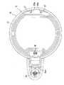
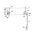
図1〜図3は本発明に係わる電動掃除機の外観図である。その図1〜図3において、1は掃除機本体である。この掃除機本体1は、ケース2とカバー部材3とから構成されている。カバー部材3はその後部が図2に示すようにヒンジ部材4を介してケース2に回動可能に取り付けられている。そのカバー部材3の前部にはホース接続口5Aが形成されている。ホース接続口5Aから後部二股部5Bに至る間の途中には掃除機本体1の握持部6が形成されている。握持部6のホース接続口5Aに近い側には操作部7が設けられると共に、操作部7の横壁にはロック解除ボタン8が設けられている。
【0012】
そのカバー部材3は図2に示すようにヒンジ部材4を介して後部を支点にして開くことができる。ケース2には電動送風機2B(図12参照)が内蔵されると共に、集塵容器9を載置する載置部10が形成されている。また、ケース2にはその上部にフィルター部材11が設けられると共に、ロック用係合凹所12を有する一対の突起部13が設けられている。カバー部材3を閉じたとき、カバー部材3に設けられている一対のロック爪3Aがロック用係合凹所12に係合し、これにより、カバー部材3がケース2にロックされ、ロック解除ボタン8を押すとロック爪3Aとロック用係合凹所12との係合が解除されて、カバー部材3を開くことができるようになっている。
【0013】
そのフィルター部材11は電動送風機2Bの直上方に位置している。そのケース2の側壁には排気口2Aが形成されている。カバー部材3には連通口14、15、16が形成されている。連通口14はホース接続口5Aに連通している。連通口15と連通口16とはカバー部材3の内部で連通され、連通口15の周囲にはパッキン部材17が設けられ、カバー部材3を閉じたときに連通口16がフィルター部材11に対向すると共に、パッキン部材17によって連通口16とパッキン部材17との間がシールされるようになっている。
【0014】
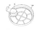
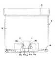
集塵容器9はその筒状容器本体18の底部に図4に示すように底蓋19が設けられ、その前部には把持部20が設けられている。その筒状容器本体18の上部にはフィルター挿着部21が図5に示すように設けられている。そのフィルター挿着部21には、図3に示すようにフィルターセット部材22が着脱可能にセットされる。
【0015】
フィルターセット部材22は図6、図7に示す下部材22Aと図8に示す上部材22Bとから構成され、両部材22A、22B間に図示を略すフィルターが挟着固定される。下部材22Aにはその前部にツマミ部23が形成されると共に、カバー部材3を閉じたときに連通口14に対向する吸引筒24が形成されている。その吸引筒24の下部口部には風向板25が図7に示すように形成されている。上部材22Bにはツマミ部26が形成されている。
【0016】
筒状容器本体18の後部側の底部には、一対の回動支持壁27が図5、図9に示すように形成されている。この回動支持壁27には嵌合凹所28aが形成されている。底蓋19の後部には突起板部29aが形成され、突起板部29aには嵌合凹所28aに回動可能に嵌合支持される嵌合軸部30aが形成され、底蓋19は嵌合軸部30aを支点にして回動可能である。
【0017】
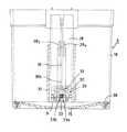
把持部20は図10に示すように筒状容器本体18への挿着部28を有する。その挿着部28は中空状とされ、その中空状の挿着部28の下部にはクランプ機構29が設けられている。このクランプ機構29は回動支持壁30と、回動支持壁30に回動可能に支持されたシャフト31と、シャフト31と一体のクランプ部材32と、ネジリコイルスプリング33とを備えている。
【0018】
ネジリコイルスプリング33の一端33aは図11に示すように挿着部28の内壁に当接され、ネジリコイルスプリング33の他端32bはクランプ部材32に当接され、クランプ部材32はネジリコイルスプリング33によってシャフト31を支点にして回動可能にかつクランプ方向(矢印Z方向)に付勢されている。
【0019】
そのクランプ部材32は図11、図12に示すように底蓋19の前部に形成されたかぎ爪19aと係合するクランプ爪32aと後述するクランプ解除バーが係合する係合当接部32bとから構成されている。
【0020】
把持部20の上部には図3〜図5に示すようにクランプ解除ボタン34が設けられている。このクランプ解除押しボタン部材34は図4に示すコイルスプリング35により把持部20から上方に突出する方向に付勢されている。そのクランプ解除押しボタン部材34はその基部34aが把持部20の上部内壁に当接することによりその突出量が規定されている。その基部34aにクランプ解除バー36の一端部36aが取り付けられ、その他端部36bは係合当接部32bに当接可能に臨んでいる。挿着部28の内部には、一対のガイド突起28yが図10に示すように設けられると共に、図4に示すように、一対のガイド突起28z、28zが上下方向に間隔を開けて設けられている。これにより、クランプ解除バー36が上下方向にスムーズに案内されるようになっている。
【0021】
カバー部材3にはそのホース接続口5Aの直下部にクランプ解除押しボタン部材34の周囲を包囲しつつ被覆する被覆カバー37が形成され、そのクランプ解除押しボタン部材34は、ケース2とカバー部材3とによって集塵容器9を挟持固定した状態で、その被覆カバー37によって被覆される。従って、ホースの着脱時にゴミがクランプ解除押しボタン部材34の周囲に落ちて付着することがなく、クランプ解除押しボタン部材34と把持部20の開口34Aとの間の隙間に詰まって、クランプ解除押しボタン部材34が動かなくなるということを確実に防止できる。
【0022】
図1に示す状態で、図示を略す吸引ホースをホース接続口5Aに接続し、空気を吸い込みを始めると、ホース接続口5A、連通口14、吸引筒24にゴミと共に吸引空気が導かれ、吸引筒24に設けた風向板25によって筒状容器本体18の内周壁に沿って周回り方向の渦巻き風(サイクロン風)となって図12に示すように集塵容器9に導かれ、集塵容器9内で減速されつつ中心部に向かい、中心部に設けられたフィルターを通って連通口15に導かれ、その連通口15、16を経由してフィルター部材11に導かれ、ケース2内を通って排気口2Aから排出される。
【0023】
その集塵容器9に導かれた吸引空気内のゴミのうち重量の大きなものは、集塵容器9内で吸引空気が減速される際に落下して集塵容器9内に溜まり、重量の軽い細かなゴミは集塵容器9の上部に設置のフィルター、ケース2の上部に設置のフィルター部材11で除去される。
【0024】
集塵容器9内に溜まったゴミを捨てるときには、カバー部材3を開けて把持部20を握って、ケース2から集塵容器9を取り外し、クランプ解除押しボタン部材34を押下すると、図13(a)に矢印Aで示すようにクランプ解除バー36の他端部36bが係合当接部32bに向かって下降し、図13(b)に示すように、係合当接部32bにクランプ解除バー36の他端部36bが当接すると、クランプ部材32がネジリコイルスプリング33のクランプ方向の付勢力に抗して、シャフト31を支点にしてクランプ方向と反対方向に回動され、かぎ爪19aとクランプ爪32aとの係合が解除され、更に、クランプ解除バー36が下降すると、図13(c)に示すように、係合当接部32がかぎ爪19aの頭部に当接し、図13(d)に示すように底蓋19が押されて開き、図11に示すように、底蓋19が全開状態となり、集塵容器9内のゴミが落下するので、図示を略すゴミ収集袋等に捨てることができる。
【0025】
一方、底蓋19を開けると、クランプ部材32はネジリコイルスプリング33によってクランプ方向に復帰する。底蓋19を閉じるときには、かぎ爪19aの頭部がクランプ爪32のテーパー面32cに押され、これにより、クランプ解除方向にクランプ部材32が回動され、かぎ爪19aの頭部がクランプ爪32aを通り越した時点でかぎ爪19aの頭部によるクランプ爪32aの押圧が解除されるので、クランプ爪32aがネジリコイルスプリング33の付勢力によりクランプ方向に回動され、再び底蓋19がクランプされる。
【0026】
また、掃除中にクランプ解除押しボタン部材34が押されないようにするのに別部材を用いているので構成が簡単である。
【0027】
なお、底蓋19にはシール用パッキン38が設けられ、底蓋19を閉じると、その底部がシール用パッキン38によりシールされる。
【0028】
【発明の効果】
本発明によれば、集塵容器の底蓋のクランプを解除するクランプ解除押しボタン部材が掃除機本体のカバー部材により被覆されているので、集塵容器の把持部を握って掃除機本体のカバー部材を開いて集塵容器を掃除機本体から取り外そうとするときに、誤ってクランプ解除押しボタン部材に手が触れて把持部を握って掃除機本体のカバー部材を開くときに底蓋が開いてせっかく集塵したゴミが集塵容器から不意にこぼれ落ちるのを防止できる。
また、クランプ解除押しボタン部材が集塵容器の把持部の上部に設けられているので、集塵容器の把持部を握った状態でクランプ解除押しボタン部材を操作し易い。
【図面の簡単な説明】
【図1】 本発明の掃除機を示す外観図で、カバー部材を閉じた状態を示す図である。
【図2】 本発明の掃除機を示す外観図で、カバー部材を開いて集塵容器を取り外した状態を示す図である。
【図3】 本発明の掃除機を示す外観図で、カバー部材を開いて集塵容器をケースにセットした状態を示す図である。
【図4】 集塵容器の概略構成を示す断面図である。
【図5】 集塵容器を上面側から見た概略構成を示す図である。
【図6】 図3に示すフィルターセット部材の下部材を示す外観図である。
【図7】 図6に示す下部材の平面図である。
【図8】 図8に示す上部材の平面図である。
【図9】 図3に示す集塵容器を後部側から見た図である。
【図10】 図3に示す集塵容器の一部を破断して前面側から見た図である。
【図11】 図4に示す集塵容器の底蓋を開けた状態を示す図である。
【図12】 本発明の掃除機の吸引空気の流れを示す説明図である。
【図13】 本発明のクランプ機構の作用を説明するための説明図であり、(a)はクランプ解除押しボタンを押す前の状態を示し、(b)はクランプ解除押しボタンの押下によりクランプ解除バーの他端部の下端がクランプ部材の係合当接部に当接した状態を示し、(c)はクランプ部材が底蓋に形成のかぎ爪に当接してかぎ爪を押下している状態を示し、(d)はクランプ部材とかぎ爪との係合が解除されて、底蓋が開いた状態を示している。
【符号の説明】
1…掃除機本体
2…ケース
3…カバー部材
9…集塵容器
18…筒状容器本体
19…底蓋
20…把持部
32…クランプ部材
34…クランプ解除押しボタン部材[0001]
BACKGROUND OF THE INVENTION
According to the present invention, a vacuum cleaner body includes a case in which an electric blower is incorporated and a support portion that supports a dust collection container, and the case is rotatably provided and sandwiches the dust collection container in cooperation with the case. The present invention relates to an improvement of an electric vacuum cleaner that includes a cover member.
[0002]
[Prior art]
Conventionally, in a vacuum cleaner, the vacuum cleaner body has a built-in electric blower and a support portion that supports the dust collection container, and the case is rotatably provided with the dust collection container. And a cover member that is sandwiched in cooperation with the device is known.
[0003]
In this conventional vacuum cleaner, the dust collecting container is provided with a gripping part, and when removing dust accumulated in the dust collecting container, the cover member is opened, the gripping part is held, the dust collecting container is removed from the case, and the upper part is The detachable filter member is removed from the dust collecting container and the trash is discarded.
[0004]
[Problems to be solved by the invention]
However, in this conventional electric vacuum cleaner, when throwing away the dust accumulated in the dust collection container, the cover member of the vacuum cleaner body is opened, the gripping part is held, the dust collection container is removed from the case, and then the filter member is removed. It must be removed from the dust container and the dust container must be turned upside down to throw away the garbage, which is troublesome.
[0005]
Therefore, a dust cover is provided with a bottom cover, and a clamp member is provided on the dust collection container so that the dust can be disposed by opening and closing the bottom cover, and a clamp release push button member is linked to the clamp member. In addition, vacuum cleaners are being developed that can open the bottom lid by operating the clamp release push-button member to facilitate the disposal of dust, but there is a possibility that the clamp release push-button member may be accidentally pressed. If the clamp release push button member is pressed unintentionally, the bottom cover clamp is already released before the cover member is opened. There is a risk of spilling trash spilling when removing.
[0006]
The present invention has been made in view of the above circumstances, and the object of the present invention is to provide a bottom cover at the bottom of the dust collecting container and to facilitate disposal of dust by opening and closing the bottom cover. It is in providing the vacuum cleaner which can eliminate the malfunction in the case of doing.
[0007]
[Means for Solving the Problems]
According to a first aspect of the present invention, the main body of the vacuum cleaner includes a case having a built-in electric blower and a support part for supporting the dust collecting container, and the case is provided rotatably with the dust collecting unit. A cover member that holds the container in cooperation with the case, and the dust collection container isprovided in a cylindrical container body having a gripping portionextending in thevertical direction, and is openable and closable at the bottom of the cylindrical container body A clamp that is provided on the cylindrical container body and clamps the bottom lid; and a clamp thatis provided onan upper portionof the grip portion and that is linkedto the clamp member to release the clamp of the bottom lid. is composed of a release push button member,said cover member is a hose connecting port is formed on the front part, the hose connecting port is located above the clamp releasing push button member, immediately below the hose connecting port Coating cover covering while surrounding the periphery of the clamp releasing push button member is provided on, in a state where the dust collection container is held between the cover member and the case, the clamp releasingthe pushbutton member It iscovered with the covering cover so as not to beoperated .
[0008]
According to the present invention, the clamp release push button member for releasing the clamp of the bottom cover of the dust collecting container is covered with the cover member of the cleaner body. When you try to open the member and remove the dust container from the vacuum cleaner body, the bottom cover will pop up when you accidentally touch the clamp release pushbutton member and grasp the grip to open the vacuum cleaner cover member. It is possible to prevent trash spilled from the dust collection container from unintentionally spilling from the dust collection container.
Further, since the clamp release push button member is provided on the upper part of the gripping portion of the dust collecting container, it is easy to operate the clamp release push button member while holding the gripping portion of the dust collection container.
[0011]
DETAILED DESCRIPTION OF THE INVENTION
1 to 3 are external views of an electric vacuum cleaner according to the present invention. 1 to 3,
[0012]
The
[0013]
The
[0014]
As shown in FIG. 4, the
[0015]
The
[0016]
A pair of
[0017]
As shown in FIG. 10, the
[0018]
As shown in FIG. 11, one
[0019]
As shown in FIGS. 11 and 12, the
[0020]
A
[0021]
The
[0022]
In the state shown in FIG. 1, when a suction hose (not shown) is connected to the
[0023]
Of the dust in the suction air that has been guided to the
[0024]
When the dust accumulated in the
[0025]
On the other hand, when the
[0026]
Further, since another member is used to prevent the clamp release
[0027]
The
[0028]
【The invention's effect】
According to the present invention, the clamp release push button member for releasing the clamp of the bottom cover of the dust collecting container is covered with the cover member of the cleaner body. When you try to open the member and remove the dust container from the vacuum cleaner body, the bottom cover will pop up when you accidentally touch the clamp release pushbutton member and grasp the grip to open the vacuum cleaner cover member. It is possible to prevent trash spilled from the dust collection container from unintentionally spilling from the dust collection container.
Further, since the clamp release push button member is provided on the upper part of the gripping portion of the dust collecting container, it is easy to operate the clamp release push button member while holding the grip portion of the dust collection container.
[Brief description of the drawings]
FIG. 1 is an external view showing a vacuum cleaner according to the present invention, and shows a state in which a cover member is closed.
FIG. 2 is an external view showing the vacuum cleaner of the present invention, and shows a state where a cover member is opened and a dust collecting container is removed.
FIG. 3 is an external view showing the vacuum cleaner of the present invention, and shows a state where a cover member is opened and a dust collecting container is set in a case.
FIG. 4 is a cross-sectional view showing a schematic configuration of a dust collecting container.
FIG. 5 is a diagram showing a schematic configuration of a dust collection container as viewed from the upper surface side.
6 is an external view showing a lower member of the filter set member shown in FIG. 3. FIG.
7 is a plan view of the lower member shown in FIG. 6. FIG.
FIG. 8 is a plan view of the upper member shown in FIG.
9 is a view of the dust container shown in FIG. 3 as viewed from the rear side.
10 is a view in which a part of the dust collecting container shown in FIG. 3 is broken and viewed from the front side.
11 is a view showing a state in which the bottom cover of the dust collecting container shown in FIG. 4 is opened.
FIG. 12 is an explanatory diagram showing the flow of suction air of the vacuum cleaner of the present invention.
13A and 13B are explanatory views for explaining the operation of the clamp mechanism of the present invention, in which FIG. 13A shows a state before the clamp release push button is pressed, and FIG. 13B shows the clamp release by pressing the clamp release push button. The state where the lower end of the other end of the bar is in contact with the engagement contact portion of the clamp member is shown, and (c) is the state where the clamp member is in contact with the claw formed on the bottom cover and presses the claw (D) shows a state in which the engagement between the clamp member and the claw is released and the bottom cover is opened.
[Explanation of symbols]
DESCRIPTION OF
Claims (1)
Translated fromJapanese前記集塵容器が、上下方向に延びる把持部を有する筒状容器本体と、該筒状容器本体の底部に開閉可能に設けられた底蓋と、前記筒状容器本体に設けられて前記底蓋をクランプするクランプ部材と、前記把持部の上部に設けられかつ前記クランプ部材に連係されて前記底蓋のクランプを解除するクランプ解除押しボタン部材とから構成され、
前記カバー部材にはその前部にホース接続口が形成され、該ホース接続口は前記クランプ解除押しボタン部材の上方に位置され、前記ホース接続口の直下部には前記クランプ解除押しボタン部材の周囲を包囲しつつ被覆する被覆カバーが設けられ、前記集塵容器が前記ケースと前記カバー部材とで挟持された状態のときに、前記クランプ解除押しボタン部材が前記被覆カバーにより操作不能に被覆されていることを特徴とする電気掃除機。A case in which the main body of the vacuum cleaner has an electric blower and a support part for supporting the dust collecting container, and a cover member that is rotatably provided in the case and holds the dust collecting container in cooperation with the case And consists of
The dust container is a cylindrical container body having a grip portionextending in thevertical direction, a bottom lid provided at the bottom of the cylindrical container body so as to be openable and closable, and the bottom lid provided on the cylindrical container body. A clamp member that clamps the clamp, and a clamp release push button member thatis provided atan upper portionof the grip portion and that is linkedto the clamp member to release the clamp of the bottom lid,
The cover member has a hose connection port formed at a front portion thereof, and the hose connection port is positioned above the clamp release push button member, and immediately below the hose connection port is around the clamp release push button member. A covering cover is provided to surround and cover the dust collecting container, and when the dust collecting container is sandwiched between the case and the cover member, the clamp release pushbutton member iscovered with thecovering cover so as not to beoperated. A vacuum cleaner characterized by
Priority Applications (1)
| Application Number | Priority Date | Filing Date | Title |
|---|---|---|---|
| JP2001207545AJP3656835B2 (en) | 2001-07-09 | 2001-07-09 | Electric vacuum cleaner |
Applications Claiming Priority (1)
| Application Number | Priority Date | Filing Date | Title |
|---|---|---|---|
| JP2001207545AJP3656835B2 (en) | 2001-07-09 | 2001-07-09 | Electric vacuum cleaner |
Publications (2)
| Publication Number | Publication Date |
|---|---|
| JP2003019095A JP2003019095A (en) | 2003-01-21 |
| JP3656835B2true JP3656835B2 (en) | 2005-06-08 |
Family
ID=19043510
Family Applications (1)
| Application Number | Title | Priority Date | Filing Date |
|---|---|---|---|
| JP2001207545AExpired - Fee RelatedJP3656835B2 (en) | 2001-07-09 | 2001-07-09 | Electric vacuum cleaner |
Country Status (1)
| Country | Link |
|---|---|
| JP (1) | JP3656835B2 (en) |
Cited By (3)
| Publication number | Priority date | Publication date | Assignee | Title |
|---|---|---|---|---|
| US11013378B2 (en) | 2018-04-20 | 2021-05-25 | Omachon Intellectual Property Inc. | Surface cleaning apparatus |
| US11229335B2 (en) | 2007-08-29 | 2022-01-25 | Omachron Intellectual Property Inc. | Cyclonic surface cleaning apparatus |
| US12004700B2 (en) | 2007-08-29 | 2024-06-11 | Omachron Intellectual Property Inc. | Cyclonic surface cleaning apparatus |
Families Citing this family (27)
| Publication number | Priority date | Publication date | Assignee | Title |
|---|---|---|---|---|
| GB2440125A (en)* | 2006-07-18 | 2008-01-23 | Dyson Technology Ltd | Cyclonic separating apparatus |
| JP2008093342A (en)* | 2006-10-16 | 2008-04-24 | Sharp Corp | Electric vacuum cleaner |
| KR101026065B1 (en) | 2008-08-18 | 2011-04-04 | 엘지전자 주식회사 | Cover opening and closing means of the cleaner and cover opening and closing structure using the same |
| GB0821827D0 (en)* | 2008-11-28 | 2009-01-07 | Dyson Technology Ltd | Separating apparatus for a cleaning aplliance |
| DE102009035619A1 (en)* | 2009-07-31 | 2011-04-21 | BSH Bosch und Siemens Hausgeräte GmbH | Vacuum cleaner with Staubabscheideeinheit |
| JP5691015B2 (en)* | 2010-09-03 | 2015-04-01 | パナソニックIpマネジメント株式会社 | Dust collector and vacuum cleaner |
| JP5907038B2 (en)* | 2012-10-18 | 2016-04-20 | 三菱電機株式会社 | Electric vacuum cleaner |
| GB2508035B (en)* | 2012-11-20 | 2015-03-11 | Dyson Technology Ltd | Cleaning appliance |
| AU2017227414C1 (en)* | 2016-02-29 | 2019-10-24 | Lg Electronics Inc. | Vacuum cleaner |
| AU2017227351B2 (en) | 2016-02-29 | 2019-07-18 | Lg Electronics Inc. | Vacuum cleaner |
| TWI637718B (en) | 2016-02-29 | 2018-10-11 | Lg電子股份有限公司 | Vacuum cleaner |
| TWI643596B (en) | 2016-02-29 | 2018-12-11 | Lg電子股份有限公司 | Vacuum cleaner |
| TWI643597B (en) | 2016-02-29 | 2018-12-11 | Lg電子股份有限公司 | Vacuum cleaner |
| DE202017000985U1 (en) | 2016-02-29 | 2017-05-29 | Lg Electronics Inc. | vacuum cleaner |
| TWI664944B (en)* | 2016-02-29 | 2019-07-11 | Lg電子股份有限公司 | Vacuum cleaner |
| KR101922301B1 (en) | 2016-08-25 | 2018-11-26 | 엘지전자 주식회사 | Vacuum cleaner |
| TWI653962B (en) | 2016-02-29 | 2019-03-21 | Lg電子股份有限公司 | Vacuum cleaner |
| DE112017000532B4 (en) | 2016-02-29 | 2023-11-09 | Lg Electronics Inc. | Vacuum cleaner |
| TWI636758B (en) | 2016-02-29 | 2018-10-01 | Lg電子股份有限公司 | Vacuum cleaner |
| TWI626032B (en)* | 2016-02-29 | 2018-06-11 | Lg電子股份有限公司 | Vacuum cleaner |
| DE202017000984U1 (en) | 2016-02-29 | 2017-05-29 | Lg Electronics Inc. | vacuum cleaner |
| GB2564035B8 (en) | 2016-02-29 | 2021-07-07 | Lg Electronics Inc | Vacuum cleaner |
| TWI664943B (en) | 2016-02-29 | 2019-07-11 | Lg電子股份有限公司 | Vacuum cleaner |
| WO2017150862A1 (en)* | 2016-02-29 | 2017-09-08 | 엘지전자 주식회사 | Vacuum cleaner |
| TWI641353B (en) | 2016-02-29 | 2018-11-21 | Lg電子股份有限公司 | Vacuum cleaner |
| DE202017002619U1 (en) | 2016-05-20 | 2017-08-04 | Lg Electronics Inc. | vacuum cleaner |
| GB2569821B (en)* | 2017-12-30 | 2020-04-29 | Dyson Technology Ltd | A cleaning appliance |
- 2001
- 2001-07-09JPJP2001207545Apatent/JP3656835B2/ennot_activeExpired - Fee Related
Cited By (5)
| Publication number | Priority date | Publication date | Assignee | Title |
|---|---|---|---|---|
| US11229335B2 (en) | 2007-08-29 | 2022-01-25 | Omachron Intellectual Property Inc. | Cyclonic surface cleaning apparatus |
| US12004700B2 (en) | 2007-08-29 | 2024-06-11 | Omachron Intellectual Property Inc. | Cyclonic surface cleaning apparatus |
| US11013378B2 (en) | 2018-04-20 | 2021-05-25 | Omachon Intellectual Property Inc. | Surface cleaning apparatus |
| US11375861B2 (en) | 2018-04-20 | 2022-07-05 | Omachron Intellectual Property Inc. | Surface cleaning apparatus |
| US11930987B2 (en) | 2018-04-20 | 2024-03-19 | Omachron Intellectual Property Inc. | Surface cleaning apparatus |
Also Published As
| Publication number | Publication date |
|---|---|
| JP2003019095A (en) | 2003-01-21 |
Similar Documents
| Publication | Publication Date | Title |
|---|---|---|
| JP3656835B2 (en) | Electric vacuum cleaner | |
| JP2002532123A (en) | Vacuum cleaner with removable trash container | |
| EP1023864B1 (en) | Dust-collecting device for vacuum cleaner and upright type vacuum cleaner | |
| US4545794A (en) | Vacuum cleaner | |
| US20070084165A1 (en) | Dust collection unit for electric vacuum cleaner and upright electric vacuum cleaner | |
| GB2178949A (en) | Hand-held vacuum cleaner | |
| GB2456607A (en) | Dust receptacle with lid opening mechanism on handle | |
| KR20090079143A (en) | Dust bin and vacuum cleaner with same | |
| JP3656834B2 (en) | Dust collecting container and vacuum cleaner having the dust collecting container | |
| JP3938527B2 (en) | Electric vacuum cleaner | |
| JP5664284B2 (en) | Electric vacuum cleaner | |
| JP2002325704A (en) | Dust collection case and vacuum cleaner | |
| JP2003079545A (en) | Dust collector and vacuum cleaner | |
| EP0796586A2 (en) | Closure device for a vacuum cleaner dust bag | |
| JP4530950B2 (en) | Dust collection container for vacuum cleaner and vacuum cleaner having dust collection container | |
| JPS6058646B2 (en) | vacuum cleaner | |
| JPS583406Y2 (en) | vacuum cleaner | |
| JPS6314758Y2 (en) | ||
| JPS642683Y2 (en) | ||
| JPS6136207Y2 (en) | ||
| JPS642682Y2 (en) | ||
| JP2002017628A5 (en) | ||
| JP2004261334A (en) | Vacuum cleaner | |
| JPS58118726A (en) | Electric cleaner | |
| JP5125861B2 (en) | Dust collector and electric vacuum cleaner using the same |
Legal Events
| Date | Code | Title | Description |
|---|---|---|---|
| A977 | Report on retrieval | Free format text:JAPANESE INTERMEDIATE CODE: A971007 Effective date:20041028 | |
| A131 | Notification of reasons for refusal | Free format text:JAPANESE INTERMEDIATE CODE: A131 Effective date:20041102 | |
| A521 | Written amendment | Free format text:JAPANESE INTERMEDIATE CODE: A523 Effective date:20041224 | |
| TRDD | Decision of grant or rejection written | ||
| A01 | Written decision to grant a patent or to grant a registration (utility model) | Free format text:JAPANESE INTERMEDIATE CODE: A01 Effective date:20050301 | |
| A61 | First payment of annual fees (during grant procedure) | Free format text:JAPANESE INTERMEDIATE CODE: A61 Effective date:20050302 | |
| R150 | Certificate of patent or registration of utility model | Ref document number:3656835 Country of ref document:JP Free format text:JAPANESE INTERMEDIATE CODE: R150 Free format text:JAPANESE INTERMEDIATE CODE: R150 | |
| FPAY | Renewal fee payment (event date is renewal date of database) | Free format text:PAYMENT UNTIL: 20080318 Year of fee payment:3 | |
| S111 | Request for change of ownership or part of ownership | Free format text:JAPANESE INTERMEDIATE CODE: R313113 | |
| FPAY | Renewal fee payment (event date is renewal date of database) | Free format text:PAYMENT UNTIL: 20080318 Year of fee payment:3 | |
| R350 | Written notification of registration of transfer | Free format text:JAPANESE INTERMEDIATE CODE: R350 | |
| FPAY | Renewal fee payment (event date is renewal date of database) | Free format text:PAYMENT UNTIL: 20080318 Year of fee payment:3 | |
| FPAY | Renewal fee payment (event date is renewal date of database) | Free format text:PAYMENT UNTIL: 20090318 Year of fee payment:4 | |
| FPAY | Renewal fee payment (event date is renewal date of database) | Free format text:PAYMENT UNTIL: 20090318 Year of fee payment:4 | |
| S533 | Written request for registration of change of name | Free format text:JAPANESE INTERMEDIATE CODE: R313533 | |
| R350 | Written notification of registration of transfer | Free format text:JAPANESE INTERMEDIATE CODE: R350 | |
| R350 | Written notification of registration of transfer | Free format text:JAPANESE INTERMEDIATE CODE: R350 | |
| FPAY | Renewal fee payment (event date is renewal date of database) | Free format text:PAYMENT UNTIL: 20090318 Year of fee payment:4 | |
| FPAY | Renewal fee payment (event date is renewal date of database) | Free format text:PAYMENT UNTIL: 20100318 Year of fee payment:5 | |
| FPAY | Renewal fee payment (event date is renewal date of database) | Free format text:PAYMENT UNTIL: 20100318 Year of fee payment:5 | |
| FPAY | Renewal fee payment (event date is renewal date of database) | Free format text:PAYMENT UNTIL: 20110318 Year of fee payment:6 | |
| FPAY | Renewal fee payment (event date is renewal date of database) | Free format text:PAYMENT UNTIL: 20120318 Year of fee payment:7 | |
| FPAY | Renewal fee payment (event date is renewal date of database) | Free format text:PAYMENT UNTIL: 20130318 Year of fee payment:8 | |
| FPAY | Renewal fee payment (event date is renewal date of database) | Free format text:PAYMENT UNTIL: 20140318 Year of fee payment:9 | |
| S531 | Written request for registration of change of domicile | Free format text:JAPANESE INTERMEDIATE CODE: R313531 | |
| S533 | Written request for registration of change of name | Free format text:JAPANESE INTERMEDIATE CODE: R313533 | |
| R350 | Written notification of registration of transfer | Free format text:JAPANESE INTERMEDIATE CODE: R350 | |
| S111 | Request for change of ownership or part of ownership | Free format text:JAPANESE INTERMEDIATE CODE: R313115 Free format text:JAPANESE INTERMEDIATE CODE: R313117 | |
| R371 | Transfer withdrawn | Free format text:JAPANESE INTERMEDIATE CODE: R371 | |
| R350 | Written notification of registration of transfer | Free format text:JAPANESE INTERMEDIATE CODE: R350 | |
| S111 | Request for change of ownership or part of ownership | Free format text:JAPANESE INTERMEDIATE CODE: R313117 | |
| S531 | Written request for registration of change of domicile | Free format text:JAPANESE INTERMEDIATE CODE: R313531 | |
| R350 | Written notification of registration of transfer | Free format text:JAPANESE INTERMEDIATE CODE: R350 | |
| LAPS | Cancellation because of no payment of annual fees |