JP3656787B2 - Automatic opening / closing device for vehicle sliding door - Google Patents
Automatic opening / closing device for vehicle sliding doorDownload PDFInfo
- Publication number
- JP3656787B2 JP3656787B2JP02985397AJP2985397AJP3656787B2JP 3656787 B2JP3656787 B2JP 3656787B2JP 02985397 AJP02985397 AJP 02985397AJP 2985397 AJP2985397 AJP 2985397AJP 3656787 B2JP3656787 B2JP 3656787B2
- Authority
- JP
- Japan
- Prior art keywords
- sliding door
- controller
- vehicle
- door
- clutch device
- Prior art date
- Legal status (The legal status is an assumption and is not a legal conclusion. Google has not performed a legal analysis and makes no representation as to the accuracy of the status listed.)
- Expired - Fee Related
Links
- 239000007858starting materialSubstances0.000claimsdescription10
- 230000007423decreaseEffects0.000claimsdescription7
- 238000010586diagramMethods0.000description9
- 238000012544monitoring processMethods0.000description5
- 238000001514detection methodMethods0.000description3
- 230000005540biological transmissionEffects0.000description2
- 230000002093peripheral effectEffects0.000description2
- 230000000694effectsEffects0.000description1
- 238000012423maintenanceMethods0.000description1
Images


Classifications
- B—PERFORMING OPERATIONS; TRANSPORTING
- B60—VEHICLES IN GENERAL
- B60J—WINDOWS, WINDSCREENS, NON-FIXED ROOFS, DOORS, OR SIMILAR DEVICES FOR VEHICLES; REMOVABLE EXTERNAL PROTECTIVE COVERINGS SPECIALLY ADAPTED FOR VEHICLES
- B60J5/00—Doors
- B60J5/04—Doors arranged at the vehicle sides
- B60J5/06—Doors arranged at the vehicle sides slidable; foldable
- E—FIXED CONSTRUCTIONS
- E05—LOCKS; KEYS; WINDOW OR DOOR FITTINGS; SAFES
- E05F—DEVICES FOR MOVING WINGS INTO OPEN OR CLOSED POSITION; CHECKS FOR WINGS; WING FITTINGS NOT OTHERWISE PROVIDED FOR, CONCERNED WITH THE FUNCTIONING OF THE WING
- E05F15/00—Power-operated mechanisms for wings
- E05F15/60—Power-operated mechanisms for wings using electrical actuators
- E05F15/603—Power-operated mechanisms for wings using electrical actuators using rotary electromotors
- E05F15/632—Power-operated mechanisms for wings using electrical actuators using rotary electromotors for horizontally-sliding wings
- E05F15/643—Power-operated mechanisms for wings using electrical actuators using rotary electromotors for horizontally-sliding wings operated by flexible elongated pulling elements, e.g. belts, chains or cables
- E05F15/646—Power-operated mechanisms for wings using electrical actuators using rotary electromotors for horizontally-sliding wings operated by flexible elongated pulling elements, e.g. belts, chains or cables allowing or involving a secondary movement of the wing, e.g. rotational or transversal
- E—FIXED CONSTRUCTIONS
- E05—LOCKS; KEYS; WINDOW OR DOOR FITTINGS; SAFES
- E05F—DEVICES FOR MOVING WINGS INTO OPEN OR CLOSED POSITION; CHECKS FOR WINGS; WING FITTINGS NOT OTHERWISE PROVIDED FOR, CONCERNED WITH THE FUNCTIONING OF THE WING
- E05F15/00—Power-operated mechanisms for wings
- E05F15/70—Power-operated mechanisms for wings with automatic actuation
- E—FIXED CONSTRUCTIONS
- E05—LOCKS; KEYS; WINDOW OR DOOR FITTINGS; SAFES
- E05Y—INDEXING SCHEME ASSOCIATED WITH SUBCLASSES E05D AND E05F, RELATING TO CONSTRUCTION ELEMENTS, ELECTRIC CONTROL, POWER SUPPLY, POWER SIGNAL OR TRANSMISSION, USER INTERFACES, MOUNTING OR COUPLING, DETAILS, ACCESSORIES, AUXILIARY OPERATIONS NOT OTHERWISE PROVIDED FOR, APPLICATION THEREOF
- E05Y2201/00—Constructional elements; Accessories therefor
- E05Y2201/20—Brakes; Disengaging means; Holders; Stops; Valves; Accessories therefor
- E05Y2201/214—Disengaging means
- E05Y2201/216—Clutches
- E—FIXED CONSTRUCTIONS
- E05—LOCKS; KEYS; WINDOW OR DOOR FITTINGS; SAFES
- E05Y—INDEXING SCHEME ASSOCIATED WITH SUBCLASSES E05D AND E05F, RELATING TO CONSTRUCTION ELEMENTS, ELECTRIC CONTROL, POWER SUPPLY, POWER SIGNAL OR TRANSMISSION, USER INTERFACES, MOUNTING OR COUPLING, DETAILS, ACCESSORIES, AUXILIARY OPERATIONS NOT OTHERWISE PROVIDED FOR, APPLICATION THEREOF
- E05Y2201/00—Constructional elements; Accessories therefor
- E05Y2201/20—Brakes; Disengaging means; Holders; Stops; Valves; Accessories therefor
- E05Y2201/23—Actuation thereof
- E05Y2201/246—Actuation thereof by auxiliary motors, magnets, springs or weights
- E—FIXED CONSTRUCTIONS
- E05—LOCKS; KEYS; WINDOW OR DOOR FITTINGS; SAFES
- E05Y—INDEXING SCHEME ASSOCIATED WITH SUBCLASSES E05D AND E05F, RELATING TO CONSTRUCTION ELEMENTS, ELECTRIC CONTROL, POWER SUPPLY, POWER SIGNAL OR TRANSMISSION, USER INTERFACES, MOUNTING OR COUPLING, DETAILS, ACCESSORIES, AUXILIARY OPERATIONS NOT OTHERWISE PROVIDED FOR, APPLICATION THEREOF
- E05Y2201/00—Constructional elements; Accessories therefor
- E05Y2201/40—Motors; Magnets; Springs; Weights; Accessories therefor
- E05Y2201/46—Magnets
- E05Y2201/462—Electromagnets
- E—FIXED CONSTRUCTIONS
- E05—LOCKS; KEYS; WINDOW OR DOOR FITTINGS; SAFES
- E05Y—INDEXING SCHEME ASSOCIATED WITH SUBCLASSES E05D AND E05F, RELATING TO CONSTRUCTION ELEMENTS, ELECTRIC CONTROL, POWER SUPPLY, POWER SIGNAL OR TRANSMISSION, USER INTERFACES, MOUNTING OR COUPLING, DETAILS, ACCESSORIES, AUXILIARY OPERATIONS NOT OTHERWISE PROVIDED FOR, APPLICATION THEREOF
- E05Y2400/00—Electronic control; Electrical power; Power supply; Power or signal transmission; User interfaces
- E05Y2400/10—Electronic control
- E05Y2400/50—Fault detection
- E05Y2400/512—Fault detection of electric power
- E—FIXED CONSTRUCTIONS
- E05—LOCKS; KEYS; WINDOW OR DOOR FITTINGS; SAFES
- E05Y—INDEXING SCHEME ASSOCIATED WITH SUBCLASSES E05D AND E05F, RELATING TO CONSTRUCTION ELEMENTS, ELECTRIC CONTROL, POWER SUPPLY, POWER SIGNAL OR TRANSMISSION, USER INTERFACES, MOUNTING OR COUPLING, DETAILS, ACCESSORIES, AUXILIARY OPERATIONS NOT OTHERWISE PROVIDED FOR, APPLICATION THEREOF
- E05Y2400/00—Electronic control; Electrical power; Power supply; Power or signal transmission; User interfaces
- E05Y2400/61—Power supply
- E05Y2400/612—Batteries
- E—FIXED CONSTRUCTIONS
- E05—LOCKS; KEYS; WINDOW OR DOOR FITTINGS; SAFES
- E05Y—INDEXING SCHEME ASSOCIATED WITH SUBCLASSES E05D AND E05F, RELATING TO CONSTRUCTION ELEMENTS, ELECTRIC CONTROL, POWER SUPPLY, POWER SIGNAL OR TRANSMISSION, USER INTERFACES, MOUNTING OR COUPLING, DETAILS, ACCESSORIES, AUXILIARY OPERATIONS NOT OTHERWISE PROVIDED FOR, APPLICATION THEREOF
- E05Y2900/00—Application of doors, windows, wings or fittings thereof
- E05Y2900/50—Application of doors, windows, wings or fittings thereof for vehicles
- E05Y2900/53—Type of wing
- E05Y2900/531—Doors
Landscapes
- Engineering & Computer Science (AREA)
- Mechanical Engineering (AREA)
- Power-Operated Mechanisms For Wings (AREA)
Description
Translated fromJapanese【0001】
【発明の属する技術分野】
本発明は、モータ等の駆動源の駆動力を電磁クラッチを介してスライドドアに伝達し、スライドドアを開閉移動させる車輛用スライドドアの自動開閉装置に関する。
【0002】
【従来の技術】
従来から車体の側面に前後方向にスライド可能に取り付けたスライドドアを、モータ等の駆動源によって開閉移動するようにした車輛用スライドドアの自動開閉装置が知られている。この装置は運転席やドアハンドルの近くに設けた操作子を使用者が意識的に操作することによって、コントローラを介して駆動源を起動し、スライドドアを開閉移動するものである。
【0003】
また、この装置は駆動源とスライドドアとの間に介在する電磁クラッチの伝達維持力をコントローラで制御することによって、車輛が坂道に停止した場合にスライドドアが動き出さないように、あるいは手動による開閉操作が可能なように保持するようにしている。
【0004】
【発明が解決しようとする課題】
前述した従来技術において、コントローラに電源を供給するバッテリーが劣化してくると、エンジンの始動時などにバッテリーの出力電圧が低下し、それによってコントローラが作動を停止するという不都合が生じる。コントローラが作動を停止すると、電磁クラッチがオフ(断)となり、車輛が坂道に停止しているとスライドドアが自重で落下してしまうという不都合が生じる。
【0005】
とくに、コントローラにマイクロコンピュータ(以下、マイコン、という)を使用している場合は、低電圧時の暴走を防止するために、電源電圧が低下するとマイコンをリセットしている。このため、電磁クラッチの能力としてはスライドドアを保持できる電源電圧であっても、マイコンそのものがリセットされてしまうので、制御不能となり、電磁クラッチがオフしてしまう。
【0006】
また、一定の電源電圧以下では作動を停止させる装置もあるが、この場合はバッテリーが無負荷時のときの電圧を監視するので、バッテリーの特性上、バッテリーが劣化していても見掛け上の電圧が正常に近い場合があり、スライドドア起動後に電圧が低下すると、例えばスライドドアの作動途中でエンジンを始動させた途端に電圧が低下し、コントローラがリセットされてしまうなどの不都合が生じる。
【0007】
本発明は、このような従来の課題を解決するためになされたもので、電源電圧が低下してコントローラが作動しなくなった場合でも、スライドドアを停止保持することができる車輛用スライドドアの自動開閉装置を提供することを目的とする。
【0008】
【課題を解決するための手段】
本発明の請求項1記載の発明は、車体に設けたガイドトラックに沿ってスライドドア移動機構により開閉移動されるスライドドアと、駆動源の動力をスライドドア移動機構に断続自在に伝達するクラッチ装置と、クラッチ装置を断続制御すると共に、電源電圧が一定値以下に低下すると自体の制御を停止するコントローラと、車輛エンジン始動時にクラッチ装置に電源電圧を直接供給してクラッチ装置を強制的に接続する切替え回路とを備える。
【0009】
本発明の請求項2に記載の発明は、請求項1記載の発明において、車輛エンジン始動の検出は、イグニッションスイッチがスタータポジションにあることを検出することによって行う。
【0010】
本発明の請求項3に記載の発明は、車体に設けたガイドトラックに沿ってスライドドア移動機構により開閉移動されるスライドドアと、駆動源の動力をスライドドア移動機構に断続自在に伝達するクラッチ装置と、クラッチ装置を断続制御するコントローラと、コントローラに供給される電源電圧の低下時にクラッチ装置を強制的に接続する制御回路とを備える。
【0011】
本発明の請求項4に記載の発明は、請求項1または3記載の発明において、コントローラが、電源電圧が通常電圧に復帰し、スライドドアが途中位置に停止しているときは、クラッチ装置を一定時間接続し、かつ駆動源のモータ制御によるブレーキ作用をスイッチ素子にて一定時間解放する。
【0012】
本発明によれば、スライドドアが駆動源によって開閉駆動されているときに、エンジンを始動することによって電源電圧が低下し、コントローラによるクラッチ装置の制御が不可能になるのを未然に防ぐために、エンジン始動時にはクラッチ装置を強制的に接続するようにしたため、スライドドアの急閉・急開を防止することができる。
【0013】
また、本発明によれば、スライドドアが駆動源によって開閉駆動されているときに、電源電圧の出力電圧が低下してコントローラがリセットされるような場合は、クラッチ装置を強制的に接続するようにしたため、スライドドアの急閉・急開を防止することができる。
【0014】
また、本発明によれば、電源電圧が通常電圧に復帰したときは、コントローラによってクラッチ装置を一定時間オンとし、かつ駆動源のブレーキを解放するようにしたため、車輛が坂道に停車し、スライドドアが途中位置に停止しているときは、スライドドアは駆動源等の摩擦による減速を受けながら落下方向に移動するので、スライドドアの急閉または急開を防止することができる。
【0015】
【発明の実施の形態】
図1は、本発明による車輛用スライドドアの自動開閉装置が適用された自動車の一例を示す外観斜視図で、車体1の側面にスライドドア3が前後方向に開閉可能に装着された状態を示している。図2は、スライドドア3(鎖線で示す)を取り外した状態を示す車体1の拡大斜視図であり、図3は、スライドドア3のみを単独で示す斜視図である。
【0016】
これらの図において、スライドドア3は、内側上下端にそれぞれ固設した上側摺動連結具31および下側摺動連結具32を、車体1のドア開口部11の上縁に設けた上部トラック12および下縁に設けた下部トラック13にそれぞれ連係することによって、車体1に前後方向に摺動自在に懸架されている。
【0017】
また、スライドドア3は、内側後端に取り付けたヒンジアーム33が車体1の後部ウェスト部付近に固定したガイドトラック14に摺動自在に係合して案内され、ドア開口部11を密閉した全閉位置から車体1のアウターパネルの外側面より若干外方に突出しながら車体1の外装パネル側面と平行に後方に移動し、ドア開口部11を全開させる全開位置まで移動するように装着されている。さらに、スライドドア3の外側面には、手動によって開閉操作を行うためのドアハンドル35が取り付けられている。
【0018】
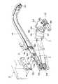
また、図4に示すように、車体1のドア開口部11の後方には、車体1を外装するアウターパネルと室内側のインナーパネルとの間に、スライドドア駆動装置5が装着されている。このスライドドア駆動装置5は、モータ駆動によってガイドトラック14内に配設されているケーブル部材51を移動させ、それによってケーブル部材51に連結されたスライドドア3を移動させるものである。
【0019】
なお、本実施の形態では、車内に設置した開閉スイッチによってスライドドア3の開閉指示を行うと共に、図1に示すように、車外からワイヤレスリモコン9によっても開閉指示を行うことができるように構成されている。この構成の詳細については後述する。
【0020】
図5は、スライドドア駆動装置5の要部を示す斜視図である。同図において、スライドドア駆動装置5は駆動部52を有し、この駆動部52は車体1の室内側にボルト等をもって固定されたベースプレート53に、正逆転可能なスライドドア開閉用の開閉モータ54と、ケーブル部材51が巻回されたドライブプーリ55と、電磁クラッチ56を内蔵する減速部57とをそれぞれ固定した構成からなっている。
【0021】
ドライブプーリ55に巻回されたケーブル部材51は、ガイドトラック14の後方に設けられた一対の案内プーリ58,58を介して外向きにコ字型に開口するガイドトラック14の上方の開口部14aと、下方の開口部14bとに互いに平行に掛け回されるとともに、ガイドトラック14の前端部に設けた反転プーリ59に巻回されて無端索条を形成している。
【0022】
また、ケーブル部材51のガイドトラック14の開口部14aを走行する部分の適所には、開口部14a内を抵抗なく走行できる状態で移動部材36が固設されている。ケーブル部材51はこの移動部材36より前方側が閉扉用ケーブル51aとなり、後方側が開扉用ケーブル51bとなっている。
【0023】
移動部材36はヒンジアーム33を介してスライドドア3の内側後端部に連結されており、開閉モータ54の回転による開扉用ケーブル51aまたは閉扉用ケーブル51bの引っ張り力によってガイドトラック14の開口部14a内を前方または後方に移動し、それによってスライドドア3を閉扉方向または開扉方向に移動させるようになっている。したがって、ケーブル部材51、案内プーリ58、反転プーリ59、ヒンジアーム33および移動部材36等によってスライドドア移動機構が構成されている。
【0024】
また、ドライブプーリ55の回転軸には、その回転角度を高分解能に計測するロータリーエンコーダ60が連係されている。ロータリーエンコーダ60はドライブプーリ55の回転角度に応じたパルス数の出力信号を発生し、ドライブプーリ55に巻回されているケーブル部材51の移動量、すなわちスライドドア3の移動量を計測できるようになっている。このため、スライドドア3の全閉位置を初期値としてロータリーエンコーダ60からのパルス数を全開位置まで計数すれば、その位置計数値Nは移動部材36の位置、すなわちスライドドア3の位置を表すことになる。
【0025】
図6は、スライドドア3の移動状況を示す概略的平面図である。前述したように、スライドドア3は、上側摺動連結具31および下側摺動連結具32が上部トラック12および下部トラック13と連係することによって前方部が保持されており、ヒンジアーム33が移動部材36を介してケーブル部材51に固設されることで後方部が保持されている。
【0026】
(スライドドア制御装置と周辺装置)
次に、図7に示すブロック図を参照しながらスライドドア制御装置7と、車体1およびスライドドア3内の各電気的要素との接続関係について説明する。スライドドア制御装置7はマイクロコンピュータによるプログラム制御によってスライドドア駆動装置5を制御するもので、例えば車体1内のモータ駆動部52の近傍に配置されている。
【0027】
スライドドア制御装置7と車体1内の各電気的要素との接続としては、直流電圧BVを受けるためのバッテリー15との接続、イグニッション信号IGを受けるためのイグニッションスイッチ16との接続、パーキング信号PKを受けるためのパーキングスイッチ17との接続、メインスイッチ信号MAを受けるためのメインスイッチ18との接続がある。
【0028】
さらに、ドア開信号DOを受けるためのドア開スイッチ19との接続、ドア閉信号DCを受けるためのドア閉スイッチ20との接続、ワイヤレスリモコン9からのリモコン開信号ROまたはリモコン閉信号RCを受けるためのキーレスシステム21との接続、スライドドア3が自動開閉されることを警告するために警報音を発生するブザー22との接続、車速信号SSを受けるための車速センサ23との接続がある。なお、ドア開スイッチ19およびドア閉スイッチ20がそれぞれ2つの操作子から構成されているのは、これらのスイッチが例えば車内の運転席と後部座席との2箇所に設置されていることを示している。
【0029】
次に、スライドドア制御装置7とスライドドア駆動装置5との接続関係は、開閉モータ54に電力を供給するための接続、電磁クラッチ56を制御するための接続、ロータリーエンコーダ60からのパルス信号を受けてパルス信号φ1、φ2を出力するパルス信号発生部61との接続などがある。
【0030】
スライドドア制御装置7とスライドドア3内の各電気的要素との接続は、スライドドア3が全閉状態から若干開いた状態でドア開口部11に設けた車体側コネクタ24とスライドドア3の開口端に設けたドア側コネクタ37とが接続されることによって可能となる。
【0031】
この接続状態でのスライドドア制御装置7とスライドドア3内の各電気的要素との接続関係としては、スライドドア3をハーフラッチ直前からフルラッチの状態にまで締め込むためのクロージャーモータ(CM)38に電力を供給するための接続、ドアロック34を駆動してストライカ25から外すためのアクチュエータ(ACTR)39に電力を供給するための接続、ハーフラッチを検出するハーフラッチスイッチ40からのハーフラッチ信号HRを受けるための接続、ドアロック34と連結しているドアハンドル35の操作を検出するドアハンドルスイッチ35aからのドアハンドル信号DHを受けるための接続などがある。なお、下部トラック13上には、スライドドア3が全開位置に達したときに、下側摺動連結具32によってオンする全開検出スイッチ65が取り付けられている。
【0032】
(要部ブロック図)
図8は、図7に示すブロック図から本発明の要部である電磁クラッチの制御部分を抽出して示すブロック図である。同図において、スライドドア制御装置7は内部にマイコンを備えるコントローラ71を有し、一定の時間間隔で繰り返し制御を行っている。
【0033】
また、スライドドア制御装置7は電源監視回路72を有し、この電源監視回路72はバッテリー15からの電源電圧を受けてコントローラ71に供給する電源電圧Vccを生成すると共に、バッテリー15の出力電圧を監視する機能を有している。
【0034】
すなわち、電源監視回路72は、バッテリー15の出力電圧が一定値以下に低下したことを検出すると、コントローラ71のリセット端子にリセット信号を出力し、コントローラ71の動作を停止させる。これはコントローラ71を構成するマイコンは、バッテリー電圧が定格電圧より低くなると暴走する可能性があるためである。定格電圧はマイコンの種類や電源回路等における電圧低下により異なるが、バッテリー電圧が6.5ボルト付近(マイコン自体への電圧で約4ボルト付近)でリセットするようにしている。
【0035】
また、スライドドア制御装置7はコントローラ71によって駆動されるクラッチ制御リレー73を有し、そのリレーコイル73Lの一端はコントローラ71のスイッチ素子TR1に接続され、他端はバッテリー15に接続されている。接点スイッチ73Sの固定端子はバッテリー15に接続され、可動端子は電磁クラッチ56の一端に接続されている。電磁クラッチ56の他端は接地されている。
【0036】
また、スライドドア制御装置7は第1および第2のモータ制御リレー74,75を有する。第1のモータ制御リレー74は、そのリレーコイル74Lの一端がコントローラ71のスイッチ素子TR2に接続され、他端がバッテリー15に接続されている。接点スイッチ74Sの可動端子は開閉モータ54の一端に接続され、2つある固定端子の一方はバッテリー15に接続され、他方はモータブレーキキャンセルリレー76の接点スイッチ76Sを介して接地されている。
【0037】
第2のモータ制御リレー75は、そのリレーコイル75Lの一端がコントローラ71のスイッチ素子TR3に接続され、他端がバッテリー15に接続されている。接点スイッチ75Sの可動端子はモータ54の他端に接続され、2つある固定端子の一方はバッテリー15に接続され他方は接地されている。
【0038】
また、スライドドア制御装置7は、モータブレーキキャンセルリレー76を有し、そのリレーコイル76Lの一端がコントローラ71のスイッチング素子TR4に接続され、他端がバッテリー15に接続されている。接点スイッチ76Sは可動端子がモータ制御リレー74の他方の固定端子に接続され、固定端子は接地されている。
【0039】
また、バッテリー15の出力はイグニッションスイッチ16を介してコントローラ71に接続され、スタータポジションスイッチ77およびダイオードD1の直列回路を介して電磁クラッチ56の一端に接続されている。
【0040】
この構成において、ドア開スイッチ19がオン操作されると、スイッチ素子TR1がオンしてクラッチ制御リレー73のリレーコイル73Lに電流が流れ、それによって接点スイッチ73Sが閉じる。接点スイッチ73Sが閉じると、電磁クラッチ56の一端がバッテリー15に接続され、他端は接地されているので、電磁クラッチ56が断状態(オフ)から接続状態(オン)になる。
【0041】
次いで、スイッチ素子TR2がオンしてモータ制御リレー74のリレーコイル74Lに電流が流れ、それによって接点スイッチ74Sが閉じる。接点スイッチ74Sが閉じると、開閉モータ54の一端がバッテリー15に接続され、開閉モータ54の他端はモータ制御リレー75を介して接地されているので、開閉モータ54はスライドドア3を開方向に駆動する方向に回転駆動される。これによって、開閉モータ54の動力が電磁クラッチ56およびドライブプーリ55を介してケーブル部材51に伝達され、スライドドア3が開方向に駆動される。
【0042】
ドア閉スイッチ20がオン操作された場合は、同様にしてスイッチ素子TR1がオンして電磁クラッチ56がオンし、次いでスイッチ素子TR3がオンしてモータ制御リレー75のリレーコイル75Lに電流が流れ、それによって接点スイッチ75Sが閉じ、開閉モータ54の他端がバッテリー15に接続される。
【0043】
開閉モータ54の一端はモータ制御リレー74およびモータブレーキキャンセルリレー76を介して接地されているので、開閉モータ54はスライドドア3を閉方向に駆動する方向に回転駆動される。これによって、開閉モータ54の動力が電磁クラッチ56およびドライブプーリ55を介してケーブル部材51に伝達され、スライドドア3が閉方向に駆動される。
【0044】
こうしてスライドドア3が開閉駆動されているときに、エンジンが始動されると、イグニッションスイッチがスタータポジションになり、スイッチ77がオンしてバッテリー15の出力電圧がダイオードD1を介して直接電磁クラッチ56の一端に供給される。
【0045】
これは、前述したようにバッテリー15が劣化しているときに、車載伝送負荷の中で最も大容量であるスタータモータが駆動されることによってバッテリー電圧が低下し、コントローラ71がリセットされてクラッチ制御リレー73からの電源供給が断たれても、電磁クラッチ56にバッテリー電圧を直接供給するためである。
【0046】
こうすることによって、バッテリー15が弱っている状態でエンジンを始動させたときの最低電圧は4ボルト付近であるので、コントローラ71のマイコンはリセットされ制御不能となるが、電磁クラッチ56は電源電圧3.5ボルト付近まで作動可能であり、しかも電磁クラッチ56は1度保持されるとヒステリシスを持っているので低電圧までオン状態に保持する。このとき開閉モータ54はコントローラ71のマイコンがリセットされたことによって停止しているので、スライドドア3も停止し、スライドドア3の自重による移動を阻止することができる。
【0047】
なお、ダイオードD1はイグニッションスイッチがスタータポジション以外のときにスタータポジションに接続されたスタータモータ等への回り込みを防止するためのものである。
【0048】
エンジンが始動してバッテリー電圧が通常電圧に復帰すると、コントローラ71も復帰する。電源復帰時に、スライドドア3が全開位置のときにオンする全開検出スイッチ65がオフで、かつハーフラッチスイッチ40もオフの場合、すなわちスライドドア3が途中位置にある場合は、コントローラ71はスイッチ素子TR1をオンして電磁クラッチ56を一定時間オンし、かつスイッチ素子TR4をオンしてモータブレーキキャンセルリレー76を一定時間オンする。リレー76がオンすると開閉モータ54のブレーキが解放される。
【0049】
こうすることによって、車輛が坂道に停車し、スライドドア3は途中位置に停止しているときでも、機構部の摩擦(とくに駆動源ギアの摩擦)による減速を受けながら落下方向に移動することになるので、スライドドア3の急閉または急開を防止することができる。また、手動力によるスライドドア3の操作も可能である。
【0050】
(他の実施の形態による要部ブロック図)
図9は、本発明の要部である電磁クラッチの制御部分を抽出して示す他の実施の形態のブロック図で、図8に示す構成要素と同一部分には同一符号を付して説明する。
【0051】
本実施の形態では、図8に示す構成において、スイッチ77およびダイオードD1の直列回路と、クラッチ制御リレー73とが削除されており、それに代えて電磁クラッチ56の一端はバッテリー15に接続され、他端はスライドドア制御装置7内のスイッチ素子81を介して接地されている。
【0052】
このスイッチ素子81はコントローラ71のスイッチ素子TR11のA出力およびスイッチ素子TR12のB出力のNAND条件を取るNAND回路82の出力によって制御される。その他の構成は前述の図8に示す構成と同様である。
【0053】
この構成において、通常作動時(電源電圧6.5ボルト以上)は、コントローラ71のマイコンが作動しているのでB出力は絶えず“H”出力となるようにスイッチ素子TR12が制御されている。従って、NAND回路82の出力はA出力の反転値となるので、スイッチ素子81をコントローラ71側で制御することが可能である。
【0054】
すなわち、A出力が“H”となればスイッチ素子81はオフとなり電磁クラッチ56もオフとなる。A出力が“L”となればスイッチ素子81はオンとなり電磁クラッチ56もオンとなる。
【0055】
電源電圧が6.5ボルト以下では、電源回路72からコントローラ71に対してリセット信号が出力され、コントローラ71はリセット状態になる。するとB出力はオープンになるが、プルダウン抵抗により“L”状態となる。これによりNAND回路82の出力はA出力の状態にかかわらず“H”状態となり、スイッチ素子81がオン、電磁クラッチ56もオンとなる。
【0056】
このとき、開閉モータ54はコントローラ71のマイコンがリセットされたことによって停止しているので、スライドドア3も停止し、スライドドア3の自重による移動を阻止することができる。このように、NAND回路82は電源電圧低下時に電磁クラッチ56を強制的にオンする制御回路としても機能する。
【0057】
電源電圧が復帰してコントローラ71が通常動作に戻ると、B出力も“H”状態に戻る。また、電源復帰時に一定時間電磁クラッチ56とモータブレーキキャンセルリレー76をオンとすることによって、前述の実施の形態と同様にスライドドア3の急閉・急開を防止することができる。
【0058】
【発明の効果】
本発明によれば、イグニッションスイッチがスタータポジションのときは電磁クラッチを強制的にオンするようにしているため、スライドドアが駆動源によって開閉駆動されているときに、エンジンを始動することによりバッテリーの出力電圧が低下し、コントローラがリセットされても、スライドドアが急閉・急開するのを防止することができる。
【0059】
また、本発明によれば、スライドドアが駆動源によって開閉駆動されているときに、エンジン始動またはそれ以外の原因によってバッテリーの出力電圧が低下してコントローラがリセットされるような場合でも、電磁クラッチを強制的にオンするようにしたため、スライドドアが急閉・急開することが防止できる。
【0060】
また、本発明によれば、電源電圧が復帰したときは、一定時間電磁クラッチをオンし、モータブレーキを解放するため、車両が坂道に停車し、スライドドアが途中位置で停止しているときは、スライドドアは機構部の摩擦を受けながら落下方向に移動するので、スライドドアの急閉・急開を防止できる。
【図面の簡単な説明】
【図1】本発明が適用される自動車の一例を示す外観斜視図である。
【図2】スライドドアを取り外した状態を示す車体の拡大斜視図である。
【図3】スライドドアを示す斜視図である。
【図4】車内側から見たスライドドアの取り付け部分を示す斜視図である。
【図5】スライドドア駆動装置の要部を示す斜視図である。
【図6】スライドドアの移動状況を示す概略的平面図である。
【図7】スライドドア制御装置と周辺の電気的要素との接続関係を示すブロック図である。
【図8】本発明の要部を抽出して示す一実施の形態のブロック図である。
【図9】本発明の要部を抽出して示す他の実施の形態のブロック図である。
【符号の説明】
1 車体
3 スライドドア
5 スライドドア駆動装置
7 スライドドア制御装置
15 バッテリー
16 イグニッションスイッチ
17 パーキングスイッチ
18 メインスイッチ
19 ドア開スイッチ
20 ドア閉スイッチ
51 ケーブル部材
52 モータ駆動部
53 ベースプレート
54 開閉モータ
55 ドライブプーリ
56 電磁クラッチ
57 減速部
58 案内プーリ
59 反転プーリ
60 ロータリーエンコーダ
65 全開検出スイッチ
71 コントローラ
72 電源監視回路
73 クラッチ制御リレー
74,75 モータ制御リレー
76 モータブレーキキャンセルリレー
77 スタータポジションスイッチ
82 NAND回路[0001]
BACKGROUND OF THE INVENTION
The present invention relates to an automatic opening / closing device for a vehicle sliding door that transmits a driving force of a driving source such as a motor to a sliding door via an electromagnetic clutch to open and close the sliding door.
[0002]
[Prior art]
2. Description of the Related Art Conventionally, there is known an automatic opening / closing device for a vehicle sliding door in which a sliding door attached to a side surface of a vehicle body so as to be slidable in the front-rear direction is opened and closed by a driving source such as a motor. In this device, when a user consciously operates an operator provided near a driver's seat or a door handle, a drive source is activated via a controller to open and close the slide door.
[0003]
In addition, this device controls the transmission maintenance force of the electromagnetic clutch interposed between the drive source and the sliding door with a controller so that the sliding door does not start when the vehicle stops on a slope or is manually opened and closed. The operation is held so that it can be operated.
[0004]
[Problems to be solved by the invention]
In the above-described prior art, when the battery that supplies power to the controller deteriorates, the output voltage of the battery decreases when the engine is started, thereby causing the inconvenience that the controller stops operating. When the controller stops operating, the electromagnetic clutch is turned off (disconnected), and if the vehicle is stopped on a slope, the sliding door falls due to its own weight.
[0005]
In particular, when a microcomputer (hereinafter referred to as “microcomputer”) is used as the controller, the microcomputer is reset when the power supply voltage decreases in order to prevent runaway at a low voltage. For this reason, even if it is the power supply voltage which can hold | maintain a sliding door as a capability of an electromagnetic clutch, since the microcomputer itself will be reset, it will become uncontrollable and an electromagnetic clutch will be turned off.
[0006]
In addition, there are devices that stop operation at a certain power supply voltage or lower, but in this case, the voltage when the battery is unloaded is monitored, so the apparent voltage even if the battery deteriorates due to the characteristics of the battery If the voltage drops after the sliding door is activated, the voltage drops as soon as the engine is started during the operation of the sliding door, and the controller is reset.
[0007]
The present invention has been made to solve such a conventional problem. An automatic sliding door for a vehicle capable of stopping and holding the sliding door even when the power supply voltage decreases and the controller does not operate. An object is to provide a switchgear.
[0008]
[Means for Solving the Problems]
Clutch according to claim 1Symbol placement aspect of the present invention is intermittently freely transfer the sliding door is opened or closed moved by a slide door moving mechanism along a guide track provided on the vehicle body, a power of the drive source to the sliding door moving mechanism The controller and the clutch device are controlled intermittently, and when the power supply voltage drops below a certain value, the control stopsitself. When the vehicle engine starts, the power supply voltage is directly supplied to the clutch device and the clutch device is forcibly connected. Switching circuit.
[0009]
According to a second aspect of the present invention, in the first aspect of the invention, the vehicle engine start is detected by detecting that the ignition switch is in the starter position.
[0010]
According to a third aspect of the present invention, there is provided a slide door that is opened and closed by a slide door moving mechanism along a guide track provided on a vehicle body, and a clutch that transmits power of a drive source to the slide door moving mechanism in an intermittent manner. And a controller for intermittently controlling the clutch device, and a control circuit for forcibly connecting the clutch device when a power supply voltage supplied to the controller decreases.
[0011]
According to a fourth aspect of the present invention, in the first or third aspect of the present invention,when the power supply voltage is restored to the normal voltage and the sliding door is stopped at the midway position, the controller operates the clutch device. It is connected for a certain period of time, and thebrake action by themotor control of the drive source is released by theswitch element for a certain period of time.
[0012]
According to the present invention, when the sliding door is driven to open and close by the drive source, the power supply voltage is lowered by starting the engine, so that the control of the clutch device by the controller becomes impossible in advance. Since the clutch device is forcibly connected when the engine is started, the sliding door can be prevented from being suddenly closed or opened.
[0013]
Further, according to the present invention, when the slide door is driven to open and close by the drive source, the clutch device is forcibly connected when the output voltage of the power supply voltage decreases and the controller is reset. As a result, the sliding door can be prevented from being suddenly closed or opened.
[0014]
Further, according to the present invention, when the power supply voltage returns to the normal voltage, the controller turns on the clutch device for a certain period of time and releases the brake of the drive source, so that the vehicle stops on the slope and the sliding door When the slide door stops at an intermediate position, the slide door moves in the dropping direction while receiving deceleration due to friction of a drive source or the like, so that the slide door can be prevented from being suddenly closed or opened.
[0015]
DETAILED DESCRIPTION OF THE INVENTION
FIG. 1 is an external perspective view showing an example of an automobile to which an automatic opening / closing device for a slide door for a vehicle according to the present invention is applied. ing. FIG. 2 is an enlarged perspective view of the
[0016]
In these drawings, the
[0017]
The sliding
[0018]
As shown in FIG. 4, a slide
[0019]
In the present embodiment, the opening / closing instruction of the
[0020]
FIG. 5 is a perspective view showing a main part of the sliding
[0021]
The
[0022]
In addition, a moving
[0023]
The moving
[0024]
Further, the
[0025]
FIG. 6 is a schematic plan view showing a moving state of the
[0026]
(Sliding door control device and peripheral device)
Next, the connection relationship between the sliding
[0027]
As for the connection between the sliding
[0028]
Further, connection with the
[0029]
Next, the connection relationship between the slide
[0030]
The connection between the sliding
[0031]
The connection relationship between the sliding
[0032]
(Main block diagram)
FIG. 8 is a block diagram showing the control part of the electromagnetic clutch, which is the main part of the present invention, extracted from the block diagram shown in FIG. In the figure, a sliding
[0033]
The slide
[0034]
That is, when the power
[0035]
The sliding
[0036]
The sliding
[0037]
The second
[0038]
Further, the slide
[0039]
The output of the
[0040]
In this configuration, when the
[0041]
Next, the switch element TR2 is turned on, a current flows through the
[0042]
When the
[0043]
Since one end of the open /
[0044]
When the engine is started when the sliding
[0045]
As described above, when the
[0046]
By doing so, since the minimum voltage when the engine is started with the
[0047]
The diode D1 is used to prevent a sneak into a starter motor or the like connected to the starter position when the ignition switch is other than the starter position.
[0048]
When the engine starts and the battery voltage returns to the normal voltage, the
[0049]
By doing so, even when the vehicle stops on a slope and the
[0050]
(Principal part block diagram according to another embodiment)
FIG. 9 is a block diagram of another embodiment in which the control part of the electromagnetic clutch, which is the main part of the present invention, is extracted and described. The same parts as those shown in FIG. .
[0051]
In the present embodiment, in the configuration shown in FIG. 8, the series circuit of the
[0052]
This
[0053]
In this configuration, during normal operation (power supply voltage of 6.5 volts or more), since the microcomputer of the
[0054]
That is, when the A output becomes “H”, the
[0055]
When the power supply voltage is 6.5 volts or less, a reset signal is output from the
[0056]
At this time, since the opening /
[0057]
When the power supply voltage is restored and the
[0058]
【The invention's effect】
According to the present invention, when the ignition switch is in the starter position, the electromagnetic clutch is forcibly turned on. Therefore, when the sliding door is driven to open and close by the drive source, the engine is started to start the battery. Even if the output voltage decreases and the controller is reset, the sliding door can be prevented from being suddenly closed or opened.
[0059]
Further, according to the present invention, when the slide door is driven to open and close by the drive source, even when the output voltage of the battery is lowered due to engine start or other causes and the controller is reset, the electromagnetic clutch Since the switch is forcibly turned on, the sliding door can be prevented from being suddenly closed or opened.
[0060]
Further, according to the present invention, when the power supply voltage is restored, the electromagnetic clutch is turned on for a certain period of time and the motor brake is released, so that the vehicle stops on a slope and the slide door stops at an intermediate position. Since the slide door moves in the dropping direction while receiving the friction of the mechanism part, the slide door can be prevented from being suddenly closed or opened.
[Brief description of the drawings]
FIG. 1 is an external perspective view showing an example of an automobile to which the present invention is applied.
FIG. 2 is an enlarged perspective view of a vehicle body showing a state where a slide door is removed.
FIG. 3 is a perspective view showing a sliding door.
FIG. 4 is a perspective view showing a mounting portion of the slide door as viewed from the inside of the vehicle.
FIG. 5 is a perspective view showing a main part of the sliding door drive device.
FIG. 6 is a schematic plan view showing a moving state of the slide door.
FIG. 7 is a block diagram showing a connection relationship between a sliding door control device and peripheral electrical elements.
FIG. 8 is a block diagram of an embodiment in which a main part of the present invention is extracted and shown.
FIG. 9 is a block diagram of another embodiment in which a main part of the present invention is extracted and shown.
[Explanation of symbols]
DESCRIPTION OF
Claims (4)
Translated fromJapanese駆動源の動力を前記スライドドア移動機構に断続自在に伝達するクラッチ装置と、
前記クラッチ装置を断続制御すると共に、電源電圧が一定値以下に低下すると自体の制御を停止するコントローラと、
車輛エンジン始動時に前記クラッチ装置に電源電圧を直接供給して前記クラッチ装置を強制的に接続する切替え回路と、を備えることを特徴とする車輛用スライドドアの自動開閉装置。A sliding door that is opened and closed by a sliding door moving mechanism along a guide track provided on the vehicle body;
A clutch device for intermittently transmitting the power of the drive source to the sliding door moving mechanism;
A controller for controlling intermittently of the clutch device andstopping its own control when the power supply voltage drops below a certain value ;
An automatic opening / closing device for a sliding door for a vehicle, comprising: a switching circuit for supplying a power supply voltage directly to the clutch device when the vehicle engine is started to forcibly connect the clutch device.
駆動源の動力を前記スライドドア移動機構に断続自在に伝達するクラッチ装置と、
前記クラッチ装置を断続制御するコントローラと、
前記コントローラに供給される電源電圧の低下時に前記クラッチ装置を強制的に接続する制御回路と、
を備えることを特徴とする車輛用スライドドアの自動開閉装置。A sliding door that is opened and closed by a sliding door moving mechanism along a guide track provided on the vehicle body;
A clutch device for intermittently transmitting the power of the drive source to the sliding door moving mechanism;
A controller for intermittently controlling the clutch device;
A control circuit for forcibly connecting the clutch device when a power supply voltage supplied to the controller decreases;
A device for automatically opening and closing a sliding door for a vehicle.
Priority Applications (3)
| Application Number | Priority Date | Filing Date | Title |
|---|---|---|---|
| JP02985397AJP3656787B2 (en) | 1997-01-30 | 1997-01-30 | Automatic opening / closing device for vehicle sliding door |
| DE19803709ADE19803709C2 (en) | 1997-01-30 | 1998-01-30 | Automatic opening and closing system for a sliding vehicle door |
| US09/016,340US6087794A (en) | 1997-01-30 | 1998-01-30 | Automatic open-and-close system for a vehicle slide door |
Applications Claiming Priority (1)
| Application Number | Priority Date | Filing Date | Title |
|---|---|---|---|
| JP02985397AJP3656787B2 (en) | 1997-01-30 | 1997-01-30 | Automatic opening / closing device for vehicle sliding door |
Publications (2)
| Publication Number | Publication Date |
|---|---|
| JPH10212867A JPH10212867A (en) | 1998-08-11 |
| JP3656787B2true JP3656787B2 (en) | 2005-06-08 |
Family
ID=12287533
Family Applications (1)
| Application Number | Title | Priority Date | Filing Date |
|---|---|---|---|
| JP02985397AExpired - Fee RelatedJP3656787B2 (en) | 1997-01-30 | 1997-01-30 | Automatic opening / closing device for vehicle sliding door |
Country Status (3)
| Country | Link |
|---|---|
| US (1) | US6087794A (en) |
| JP (1) | JP3656787B2 (en) |
| DE (1) | DE19803709C2 (en) |
Families Citing this family (33)
| Publication number | Priority date | Publication date | Assignee | Title |
|---|---|---|---|---|
| US5979114A (en)* | 1995-07-12 | 1999-11-09 | Valeo Electrical Systems, Inc. | Electronic control and method for power sliding van door with rear-center-mounted drive |
| US6904717B2 (en) | 1995-07-12 | 2005-06-14 | Valeo Electrical Systems, Inc. | Method for controlling a power sliding van door |
| US6729071B1 (en)* | 1995-10-02 | 2004-05-04 | Ohi Seisakusho Co., Ltd. | Device for automatically controlling opening and closing of a vehicle slide door |
| JP3465735B2 (en)* | 1995-10-02 | 2003-11-10 | 株式会社大井製作所 | Automatic opening and closing control of sliding doors for vehicles |
| JP3843626B2 (en)* | 1998-11-30 | 2006-11-08 | アイシン精機株式会社 | Vehicle sliding door control device |
| JP3527425B2 (en)* | 1998-12-07 | 2004-05-17 | ダイハツ工業株式会社 | Automobile sliding door guidance system |
| JP3675204B2 (en)* | 1998-12-14 | 2005-07-27 | アイシン精機株式会社 | Sliding door device for vehicle |
| WO2000079689A2 (en)* | 1999-06-17 | 2000-12-28 | Autowin Corporation | Remote controllable device for opening/closing of a window |
| JP4803870B2 (en)* | 2000-11-09 | 2011-10-26 | 株式会社ミツバ | Opening and closing device for vehicle opening and closing body |
| JP3452548B2 (en)* | 2000-12-28 | 2003-09-29 | 三井金属鉱業株式会社 | Control method of power sliding device for vehicle sliding door |
| FR2820453B1 (en)* | 2001-02-05 | 2003-09-19 | Oxford Automotive Mecanismes E | SLIDING DOOR DRIVE DEVICE OF A MOTOR VEHICLE AND VEHICLE EQUIPPED WITH SUCH A DEVICE |
| US6481783B1 (en)* | 2001-04-25 | 2002-11-19 | Delphi Technologies, Inc. | Drive mechanism for power operated slideable side door |
| DE10297326T5 (en)* | 2001-10-11 | 2004-12-23 | Mitsui Kinzoku Kogyo K.K. | Method for controlling a motor-driven sliding device for a sliding door of a vehicle |
| GB2415015B (en)* | 2001-10-11 | 2006-03-29 | Mitsui Mining & Smelting Co | Method of controlling powered sliding device for vehicle sliding door |
| DE10322122C5 (en)* | 2003-05-16 | 2010-11-11 | Kiekert Ag | motor vehicle |
| DE102004025097B4 (en)* | 2004-05-14 | 2016-06-09 | Volkswagen Ag | Outside door handle for a motor vehicle |
| DE102004063737A1 (en)* | 2004-12-29 | 2006-07-13 | Brose Fahrzeugteile Gmbh & Co. Kommanditgesellschaft, Coburg | Opening and closing system for a motor vehicle sliding door |
| WO2006086892A1 (en)* | 2005-02-18 | 2006-08-24 | Magna Closures Inc. | Compact cable drive power sliding door mechanism |
| JP4831294B2 (en)* | 2005-06-20 | 2011-12-07 | アイシン精機株式会社 | Vehicle door opening / closing control device |
| DE202005014501U1 (en)* | 2005-09-13 | 2007-02-01 | BROSE SCHLIEßSYSTEME GMBH & CO. KG | Sliding door arrangement for e.g. mini van, has coupler brought into intermediate-coupling state, so that door is held in its actual position by self-locking of drive and is adjustable by manual actuation with minimum -actuating force |
| DE102005055848B4 (en)* | 2005-11-23 | 2016-09-01 | Volkswagen Ag | Sliding door for motor vehicles |
| US7770961B2 (en)* | 2006-02-20 | 2010-08-10 | Magna Closures Inc. | Compact cable drive power sliding door mechanism |
| WO2008106037A2 (en)* | 2007-02-28 | 2008-09-04 | Corning Incorporated | Photonic crystal fibers and methods for manufacturing the same |
| JP2010116077A (en)* | 2008-11-13 | 2010-05-27 | Toyota Motor Corp | Battery deterioration determination device |
| JP5040041B2 (en)* | 2010-06-16 | 2012-10-03 | 三井金属アクト株式会社 | Open / close control device for vehicle door |
| JP5750282B2 (en)* | 2011-03-29 | 2015-07-15 | 株式会社ケーヒン | Electronic control unit |
| US8794688B2 (en)* | 2012-01-24 | 2014-08-05 | Chrysler Group Llc | Door assembly for a vehicle |
| JP5788937B2 (en)* | 2013-08-30 | 2015-10-07 | アイシン精機株式会社 | Vehicle opening / closing body control apparatus and vehicle opening / closing system |
| DE102016102878A1 (en)* | 2016-01-12 | 2017-07-13 | Kiekert Ag | Motor vehicle door lock |
| GB2550890B (en) | 2016-05-27 | 2020-02-19 | Ford Global Tech Llc | A vehicle having a braked sliding door |
| US11053725B2 (en)* | 2017-04-11 | 2021-07-06 | Overhead Door Corporation | Sliding barrier tracking system |
| DE102017207556B4 (en) | 2017-05-05 | 2023-07-13 | Volkswagen Aktiengesellschaft | Door check device for a motor vehicle and motor vehicle and operating method for a door check device |
| EP3517340A1 (en)* | 2018-01-30 | 2019-07-31 | Kwang Yang Motor Co., Ltd. | Electricity supply system of driven element of vehicle |
Family Cites Families (4)
| Publication number | Priority date | Publication date | Assignee | Title |
|---|---|---|---|---|
| US5239779A (en)* | 1990-03-22 | 1993-08-31 | Masco Industries, Inc. | Control apparatus for powered vehicle door systems |
| US5350986A (en)* | 1993-05-20 | 1994-09-27 | General Motors Corp. | Vehicle power door speed control |
| DE4345232C2 (en)* | 1993-11-30 | 1996-01-11 | Dorma Gmbh & Co Kg | Control and regulation for a door driven by an electromechanical motor |
| KR0148506B1 (en)* | 1994-03-08 | 1998-12-01 | 미야무라 신페이 | Power supply of the vehicle power latch mechanism |
- 1997
- 1997-01-30JPJP02985397Apatent/JP3656787B2/ennot_activeExpired - Fee Related
- 1998
- 1998-01-30DEDE19803709Apatent/DE19803709C2/ennot_activeExpired - Fee Related
- 1998-01-30USUS09/016,340patent/US6087794A/ennot_activeExpired - Lifetime
Also Published As
| Publication number | Publication date |
|---|---|
| US6087794A (en) | 2000-07-11 |
| DE19803709A1 (en) | 1998-10-08 |
| DE19803709C2 (en) | 2002-08-01 |
| JPH10212867A (en) | 1998-08-11 |
Similar Documents
| Publication | Publication Date | Title |
|---|---|---|
| JP3656787B2 (en) | Automatic opening / closing device for vehicle sliding door | |
| US7814704B2 (en) | Method for controlling door and door control system for vehicle | |
| US8567129B2 (en) | Vehicle door control method and system therefor | |
| US6178699B1 (en) | Open/close control system for a vehicle slide door | |
| US5105131A (en) | Power drive system for sliding door | |
| JPH10196219A (en) | Door holding control device of vehicular sliding door | |
| JPH0747585Y2 (en) | Automatic door opening device | |
| JPH03187488A (en) | Power door slide system | |
| JP2000160935A (en) | Door control | |
| US7698855B2 (en) | Sliding-door opening control apparatus | |
| WO2004025063A1 (en) | Vehicle-use automatic opening/closing device | |
| CN110206440B (en) | Stay bar falling protection system of automobile electric tail gate | |
| JP2004131931A (en) | Door control | |
| JP3723037B2 (en) | Automatic opening / closing device for vehicle opening / closing body | |
| JP2001132327A (en) | Opening/closing device of opening/closing body for vehicle | |
| JP3576483B2 (en) | Automatic sliding door control device | |
| JP3666732B2 (en) | Automatic sliding door control device | |
| JP3711516B2 (en) | Opening and closing device for vehicle opening and closing body | |
| JPH11301271A (en) | Automatic opening and closing device for vehicle slide door | |
| JP3565317B2 (en) | Automatic opening and closing device for sliding doors for vehicles | |
| JP3851117B2 (en) | Automatic opening and closing device for vehicle door | |
| JP4149860B2 (en) | Opening and closing body drive control device | |
| JP3656182B2 (en) | Automatic opening and closing device for vehicle sliding door | |
| JP3636592B2 (en) | Automatic opening and closing device for vehicle sliding door | |
| JPH10317793A (en) | Stop controller for auto slide door |
Legal Events
| Date | Code | Title | Description |
|---|---|---|---|
| A131 | Notification of reasons for refusal | Free format text:JAPANESE INTERMEDIATE CODE: A131 Effective date:20041026 | |
| A521 | Request for written amendment filed | Free format text:JAPANESE INTERMEDIATE CODE: A523 Effective date:20041220 | |
| TRDD | Decision of grant or rejection written | ||
| A01 | Written decision to grant a patent or to grant a registration (utility model) | Free format text:JAPANESE INTERMEDIATE CODE: A01 Effective date:20050301 | |
| A61 | First payment of annual fees (during grant procedure) | Free format text:JAPANESE INTERMEDIATE CODE: A61 Effective date:20050302 | |
| R150 | Certificate of patent or registration of utility model | Free format text:JAPANESE INTERMEDIATE CODE: R150 | |
| FPAY | Renewal fee payment (event date is renewal date of database) | Free format text:PAYMENT UNTIL: 20080318 Year of fee payment:3 | |
| FPAY | Renewal fee payment (event date is renewal date of database) | Free format text:PAYMENT UNTIL: 20090318 Year of fee payment:4 | |
| FPAY | Renewal fee payment (event date is renewal date of database) | Free format text:PAYMENT UNTIL: 20090318 Year of fee payment:4 | |
| FPAY | Renewal fee payment (event date is renewal date of database) | Free format text:PAYMENT UNTIL: 20100318 Year of fee payment:5 | |
| LAPS | Cancellation because of no payment of annual fees |