JP3656712B2 - Intercom and its system - Google Patents
Intercom and its systemDownload PDFInfo
- Publication number
- JP3656712B2 JP3656712B2JP36830798AJP36830798AJP3656712B2JP 3656712 B2JP3656712 B2JP 3656712B2JP 36830798 AJP36830798 AJP 36830798AJP 36830798 AJP36830798 AJP 36830798AJP 3656712 B2JP3656712 B2JP 3656712B2
- Authority
- JP
- Japan
- Prior art keywords
- call
- control device
- machine
- version information
- collective entrance
- Prior art date
- Legal status (The legal status is an assumption and is not a legal conclusion. Google has not performed a legal analysis and makes no representation as to the accuracy of the status listed.)
- Expired - Fee Related
Links
- 230000005540biological transmissionEffects0.000description14
- 238000000034methodMethods0.000description8
- 238000012544monitoring processMethods0.000description6
- 238000010586diagramMethods0.000description4
- 238000004891communicationMethods0.000description3
- 230000005236sound signalEffects0.000description2
- 230000015572biosynthetic processEffects0.000description1
- 239000004973liquid crystal related substanceSubstances0.000description1
- 230000002265preventionEffects0.000description1
- 238000003786synthesis reactionMethods0.000description1
- 239000002699waste materialSubstances0.000description1
Images


Landscapes
- Closed-Circuit Television Systems (AREA)
- Interconnected Communication Systems, Intercoms, And Interphones (AREA)
Description
Translated fromJapanese【0001】
【発明の属する技術分野】
本発明は集合住宅等において設備されるインターホーンシステム、特にインターホン等のソフトウェアのバーション情報の表示に関する。
【0002】
【従来の技術】
従来この種のインターホーンシステムは、一般的には、集合玄関機、住戸機、管理用機及び通話制御装置から構成されており、集合玄関機、住戸機及び管理用機の間での通話が可能になっている。これらの機器にはマイクロコンピュータ、ROM等が内蔵されており、その機器の制御はソフトウェアによりなされる。このため、インターホーンシステムの全体の制御処理、或いは個々の機器についての制御処理を変更する場合には、ハード部品を代えるのではなく、ソフトウェアを変更することによりなされることが多い。
【0003】
【発明が解決しようとする課題】
インターホーンシステムの通話制御装置は、その制御の中核をなすものであり、従って、端末(集合玄関機、管理用機、住戸機)との整合が必要であり、相互にそのソフトのバーションを確認する必要がある場合がある。そのような場合には、マイクロコンピュータ、ROM等にソフトウェアのバージョン情報を予め表記しておき、そして、必要があるときには機器を分解してそのソフトウェアのバーションを確認していた。このため、従来のインターホーンシステムにおいてソフトウェアのバージョンを確認するのは面倒であるという課題があった。
【0004】
本発明は、このような課題を解決するためになされたものであり、機器のソフトウェアのバーションを簡単に確認することができるようにしたインターホンシステムを提供することを目的とする。
【0005】
【課題を解決するための手段】
本発明に係るインターホンシステムは、集合玄関機、管理用機、住戸機及び通話制御装置から構成され、前記通話制御装置を介して集合玄関機、管理用機及び住戸機の間で通話を行うインターホンシステムにおいて、前記通話制御装置又は住戸機は、自機のソフトウェアのバージョン情報が格納される記憶手段と、前記バージョン情報を所定の条件下において前記集合玄関機及び前記管理用機の少なくともいずれか1個に送出して表示させる演算手段とを有する。
また、本発明に係るインターホンシステムにおいて、前記集合玄関機及び前記管理用機の少なくともいずれか1個は、自機のソフトウェアのバージョン情報が格納される記憶手段と、前記自機のバージョン情報を所定の条件下において表示させる演算手段とを有する。また、前記所定の条件下は、自機の電源投入又はリセット時である。
【0006】
【発明の実施の形態】
実施形態1.
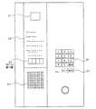
図1は本発明の一実施形態に係る集合玄関機(ロビーインターホン)の内部構成を示すブロック図である。図1において、10はマイクロコンピュータであり(これに内蔵されたROMにはそのソフトウェアのバージョン情報が格納されている)、11は制御信号線L11を介して制御信号を送受する送受信回路である。12は第1通話線L21を介して音声信号を送受信するための送受信回路、13は第2通話線L31を介して音声信号を送受信するための送受信回路、14は第1通話線の送受信回路12と第2通話線の送受信回路13とを切り替えるための切替回路である。15は増幅器、16はスピーカであり、これらは切替回路14を介して送受信回路12又は13と接続され、受信した音声信号に基づいて音声を出力する。17はマイク、18は増幅器であり、マイク17からの音声信号は増幅器18で増幅されて切替回路14を介して送受信回路12又は13に送り出される。19は音声合成回路であり、マイクロコンピュータ10の制御信号に基づいて音声信号を生成して増幅器15を介してスピーカ16に出力する。
【0007】
また、21はテレビカメラ、22はテレビカメラ21からの映像信号を切り替えるための切替回路、23は切替回路22で切り替えられた映像信号を第1映像線L41に送り出すための送信回路、24は切替回路22で切り替えられた映像信号を第2映像線L51に送り出すための送信回路である。26はテンキー、27は呼出釦、28は操作表示灯である。30はドライバ、31は7セグメント表示器である。40はシステムが1通話路か2通話路か、映像システムをもっているか等の各種の機能設定をするためのディップスイッチである。41は自機のアドレスを設定するためのロータリスイッチである。これらのスイッチ40,41は電源投入時又はリセット時に読み取られてマイクロコンピュータ10に内蔵したメモリに記憶される。
【0008】
図2は図1の集合玄関機の外観図である。図において、テレビカメラ21は左上に配置され、操作表示灯28、7セグメント表示器31が順次その下方に配置され、更に符号45に示される領域にスピーカ16及びマイク17が配置される。また、右側中央部には、テンキー26及び呼出釦27が配置される。
【0009】
図3は図1の集合玄関機(ロビーインターホン)を含む集合住宅全体のシステム構成図である。図3において、TCは通話制御装置、VCは映像制御装置、EP1,EPkはマンションなどの集合住宅の集合玄関に設けられた図1の集合玄関機、SM1,SM2は集合住宅の管理室及び管理人住戸に設けられた管理人インターホン(管理用機)である。SMPは通話制御装置TCと管理人インターホンSM1とを1つのケースに収容した管理人親機である。J1〜Jnは集合住宅の各住戸に設けられたインターホン機能を備えた住戸機に更に防犯機能を備えた住戸情報盤(以下住情盤という)である。また、L11〜L13は制御線、L21〜L23は第1通話線、L31〜L33は第2通話線、L41〜L43は第1映像線、L51〜L53は第2映像線である。また、AL1,ALKは各々集合玄関機EPI,EPKに接続されたオートドアである。
【0010】
また、図3のDP1〜DPnは各住戸の玄関の外に設けられ、その住戸の住情盤J1〜Jnに接続されたドアホン、SE1は監視線LS21〜LS2nによって住情盤J1〜Jnに接続された各住戸の玄関の防犯センサ、SE2〜SEnは監視線LS21〜LS2nによって住情盤J1〜Jnに接続された各住戸の玄関以外の部分(例えばベランダに面した窓など)に設けられた防犯センサである。なお、図3の例では、防犯センサSE1〜SEnは監視線LS21〜LS2nに接続されているが、各住戸の玄関部分に設けられた防犯センサSE1は監視線LS21〜LS2nとは別系続の監視線LS11〜LS1nに接続して玄関以外の部分に設けられた防犯センサSE2〜SEnとは別の監視動作とさせるようにしても良い。
【0011】
また、図3の住情盤J1〜Jnには、7セグメント表示器31を備えていないが、インターホンのハンドセット(送受話器)、インタホンの呼出音、管理室からの放送、警報音などを流すスピーカ、集合玄関機EP1〜EPkのテレビカメラ21から送られてくる訪問者の映像を映すLCD等のモニタテレビ、各種表示灯、各種スイッチ(例えば玄関のオートドアロックを解錠するための解錠スイッチ)や、図1のマイクロコンピュータ10と同種のマイクロコンピュータや、図3の左側の機器(符号11〜14,22〜24、40,41)に相当する機器を備えている。
【0012】
また、図3の通話制御装置TCは、集合玄関機EP1〜EPkと住戸機J1〜Jnと管理用機SM1,SM2のとの間での通話に介在するものであり、そのハードウエアとして図1のセグメント表示器31を備えていないが、図1のマイクロコンピュータ10と同種のマイクロコンピュータを備えている。
【0013】
ここで、図3のシステムの概要を、集合玄関機EP1〜EPkと住情盤J1〜Jnのインターホンとの間の例で説明する。
訪問者が例えば集合玄関機EP1のテンキー26を操作して訪問すべき部屋番号例えば「102」を入力し、次に呼出スイッチ27を押すと、集合玄関機EP1の送受信回路11から制御線L11を介して通話制御装置TCに、集合玄関機EP1のアドレスと、「102」号室の部屋コード(アドレス)と呼出コードからなる呼出信号が送出される。通話制御装置TCは集合玄関機EP1から呼出信号を受信すると、空いている通話線、映像線を調べ、第2通話線と第2映像線とが使用中であれば、呼出信号と第1通話線L22及び第1映像線L42の通話・映像線指定命令を制御線L12を介して102号室の住情盤J2に送出すると共に、第1映像線L41の映像線指定命令を制御線L11を介して集合玄関機EP1に送出する。また、制御線L61を介して映像制御装置VCに映像線L41とL42を接続する命令を送出する。集合玄関機EP1では、送受信回路11を介して上記の映像線指定命令を受信し、これにより、テレビカメラ21を起動すると共に切替回路22を制御して、テレビカメラ21の出力を送信回路23を介して第1映像線L41に接続し、第1映像線L41に訪問者の映像信号を送出する。
【0014】
また、102号室の住情盤J2は、制御線L12を通じ受信した呼出信号と第1通話線L22および第1映像線L42の通話・映像線指定命令が自機のアドレスに合致しているとき、図示しない通話用と映像用の各接続スイッチを制御して第1通話線L22及び第1映像線L42をそれぞれ接続する。また、スピーカから呼出音を発し、ロビー灯を点灯し、モニタテレビを起動して第1映像線L42により送られてくる映像信号による映像を放映する。
【0015】
住情盤J2でハンドセットが取り上げられると、ハンドセットにより押下されていた住情盤J2の図示しないフックが解放され、住情盤J2から通話制御装置TCに制御線L12を介してフックオン信号が送出される。通話制御装置TCは住情盤J2からフックオン信号を受信すると、集合玄関機EP1に対し第1通話線L21の通話線指定命令を送出し、この命令を送受信回路11を介して受け取ると、集合玄関機EP1は切替回路14を制御して送受信回路12を介して第1通話線L21と接続する。これにより集合玄関機EP1と住情盤J2との間の通話路が形成され、訪問者と102号室の居住者との間で通話が行われる。
【0016】
そして、集合玄関に配置されている入出館用の自動ドアは、住情盤J2の解錠スイッチを操作すると、制御線L12、L11を介して集合玄関機EP1に解錠信号が送られ、オートドアロックAL1が解錠されて開放される。
【0017】
また、通話が終了して住情盤J2のハンドセットHSを元に戻すと、住情盤J2から制御線L12を介して通話終了信号が通話制御装置TCに送られ、通話制御装置TCは住情盤J2と集合玄関機EP1並びに映像制御装置VCに終了命令を送出する。これにより、集合玄関機EP1はテレビカメラ21をオフすると共に、切替回路14,22を制御して第1通話線L21と第1映像線L41の接続スイッチを開放し、住情盤J2はモニタテレビをオフすると共に第1通話線L22と第1映像線L42の各接続スイッチを開放し、映像制御装置VCは第1通話線L21と第1映像線L41の接続を解放する。この結果、第1通話線と第1映像線とは解放される。
【0018】
図3のシステムの概要が明らかになったところで、次に、本実施形態に特有な構成について説明する。
【0019】
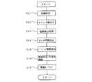
図4は図3の通話制御装置TCの電源投入又はリセット時の動作を示すフローチャートである。
▲1▼電源投入又はリセットにより装置が立ち上がり、マイクロコンピュータ(図示せず)の初期設定、RAMのクリア、I/Oポートの設定等の各種の処理を行う(S11)。
▲2▼次に、ディップスイッチやロータリスイッチの設定を読み込む(S12)。
▲3▼次に、制御信号線L11,12,通話線21,22,31,32及び映像線L41,42,51,52が短絡状態になっているかどうかの検出処理を行う(S13)。
▲4▼次に、イニシャル情報を制御信号線L11,12に送出し(S14)、続いて、その通話制御装置TCのソフトウェアのバージョン情報を制御信号線L11,12に送出する(S15)。
▲5▼その後、端末存在不存在の確認のための処理(S16)、緊急ポーリング処理(S17)等を行う。なお、前記の処理(S13,S14,S16,S17)については本発明と直接関係ないのでその説明は省略する。
【0020】
図5は集合玄関機EP1,EPkの電源投入又はリセット時の動作を示すフローチャートである。
▲1▼電源投入又はリセットにより装置が立ち上がり、マイクロコンピュータ10の初期設定、RAMのクリア、I/Oポートの設定等の各種の処理を行う(S21)。
▲2▼次に、ディップスイッチ40やロータリスイッチ41の設定を読み込む(S12)。
▲3▼そして、装置が立ち上がったことを示す例えば「イニシャル」という意味の情報表示(例えばコード番号や文字等による)を7セグメント表示器31に表示させる(S23)。
▲4▼続いて、自機である集合玄関機EP1(又はEPk)のソフトウェアのバージョン情報を内蔵したROMから読み出して7セグメント表示器31に表示させる(S24)。
▲5▼このとき、通話制御装置TCからイニシャル情報が入力されているかどうかを判断し(S25)、イニシャル情報が入力されていない場合には、受信データ処理(S26)に移行する。
【0021】
▲6▼上記にて、通話制御装置TCからイニシャル情報が入力されているという判断がなされたときには、通話制御装置TCが立ち上がった旨を示す例えば「イニシャル受信」という意味の情報表示を7セグメント表示器31に表示させる(S27)。通話制御装置TCからはイニシャル情報の後に、ソフトウェアのバージョン情報が出力されるから(図4のS14,、S15参照)、次に、通話制御装置TCのソフトウェアのバージョン情報が入力されているかどうかを判断し(S28)、バージョン情報が入力されているという判断がなされたときには、通話制御装置TCのソフトウェアのバージョン情報を7セグメント表示器31に表示させる(S29)。
【0022】
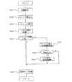
図6は図5の受信データ処理の詳細を示したフローチャートである。
▲1▼まず、受信データが正常であるかどうかを判断し(S31)、正常である場合には次の処理に移行する。
▲2▼受信データが通話制御装置TCからのイニシャル情報であるかどうかを判断し(S32)、イニシャル情報が入力されている場合には通話制御装置TCが立ち上がった旨を示す例えば「イニシャル受信」という意味の情報表示を7セグメント表示器31に表示させる(S33)。
▲3▼通話制御装置TCからはイニシャル情報の後に、ソフトウェアのバージョン情報が出力されるから(図4のS14,、S15参照)、次に、受信データが通話制御装置TCのソフトウェアのバージョン情報であるかどうかを判断し(S34)、バージョン情報であるという判断がなされたときには、通話制御装置TCのソフトウェアのバージョン情報を7セグメント表示器31に表示させる(S35)。
▲4▼また、受信データが通話先からのフックオン信号である場合には(S36)、集合玄関機EP1を通話制御状態に移行する(S37)。
【0023】
以上のようにして、集合玄関機EP1,EPkは電源投入時又はリセット時に、自機のソフトウェアのバージョン情報を表示する。また、通話制御装置TCは7セグメント表示器31を備えていないので、バージョン情報を集合玄関機EP1,EPkに出力することにより、それらにバージョン情報を表示させる。
【0024】
上記の説明は集合玄関機EP1,EPkの例であるが、管理用機SM1,SM2においても同様である。管理用機SM1,SM2においても電源投入時又はリセット時に自機のソフトウェアのバージョン情報を表示し、また、通話制御装置TCからのソフトウェアのバージョン情報を表示させる。また、上記の例では住情盤J1〜Jnには7セグメント表示器31が搭載されていないのでバージョン情報を表示することができないが、7セグメント表示器31を搭載することで上記の場合と同様にしてソフトウェアのバージョン情報を表示させることができる。
【0025】
また、通話制御装置TCのソフトウェアのバージョン情報については、集合玄関機EP1,EPk、管理用機SM1,SM2及び住情盤(上記のように表示可能にした場合)J1〜Jnの全てに表示させるようにしても良いし、何れか一方にのみ表示させるようにしても良い。更に、住情盤J1〜Jnに7セグメント表示器31を搭載しない場合には、通話制御装置TCの場合と同様に、他の機器(集合玄関機EP1,EPk、管理用機SM1,SM2)にそのソフトウェアのバージョン情報を表示させるようにしても良い。また、通話制御装置TCに表示器を設け、通話制御装置TCで各機器のバージョン情報を表示させるようにしても良い。
【0026】
なお、上記の例においては電源投入時又はリセット時にバージョン情報を表示するようにしているが、本発明はおいてはそれに限定されるものではなく、適当なコマンドを用意しておいてそのコマンドを入力したときにソフトウェアのバージョン情報を表示するようにしてもよい。
【0027】
また、上記の例においてはソフトウェアのバージョン情報を7セグメント表示器に表示させる例について説明したが、本発明の表示手段はそれに限定されるものではなく、液晶表示装置等の他の表示装置も含むものである。なお、上記実施形態では管理用機を管理室に設けた例を示したが、当該管理室以外に設けるようにしても良い。
【0028】
【発明の効果】
以上のように本発明によれば、自機のソフトウェアのバージョン情報を所定の条件下において自機又は他のインターホンの表示手段に表示させるようにしたことから、ソフトウェアのバージョンを確認する必要があるときでも、機器を分解する必要がなく、簡単にそのバーションを確認することができる。
【図面の簡単な説明】
【図1】本発明の一実施形態に係る集合住宅玄関機の内部構成を示すブロック図である。
【図2】図1の集合住宅玄関機の外観図である。
【図3】図1の集合住宅玄関機を含む集合住宅全体のシステム構成図である。
【図4】図3の通話制御装置の電源投入時又はリセット時の初期段階の動作を示したフローチャートである。
【図5】集合玄関機の電源投入時又はリセット時の初期段階の動作を示したフローチャートである。
【図6】図5の受信データ処理の詳細を示したフローチャートである。
【符号の説明】
10 マイクロコンピュータ
30 ドライバ
31 7セグメント表示器[0001]
BACKGROUND OF THE INVENTION
The present invention relates to an interphonesystem installed in an apartment house or the like,and more particularly to displaying version information of software such as an interphone.
[0002]
[Prior art]
Conventionally, this type of interphone system is generally composed of a collective entrance unit, a dwelling unit, a management unit and a call control device, and calls between the collective entrance unit, the dwelling unit and the management unit can be made. It is possible. These devices incorporate a microcomputer, ROM, and the like, and the devices are controlled by software. For this reason, when changing the overall control process of the interphone system or the control process for individual devices, it is often done by changing the software instead of replacing the hardware components.
[0003]
[Problems to be solved by the invention]
The communication control device of the interphone system is the core of the control. Therefore, it is necessary to match the terminal (collection entrance machine, management machine, dwelling unit), and the software version can be exchanged with each other. You may need to check. In such a case, software version information is written in advance in a microcomputer, ROM, etc., and when necessary, the device is disassembled to check the software version. For this reason, there is a problem that it is troublesome to check the software version in the conventional interphone system.
[0004]
The present invention has been made to solve such a problem, and an object of the present invention is to provide an intercomsystem in which the software version of the device can be easily confirmed.
[0005]
[Means for Solving the Problems]
The intercom system according to the present invention is composed of a collective entrance machine, a management machine, a dwelling unit, and a call control device, and performs intercom calls between the collective entrance device, the management machine, and the dwelling unit via the call control device. In the system, the call control device or the dwelling unit has at least one of storage means for storing version information of its own software, and the collective entrance machine and the management machine under the predetermined condition of the version information. Computing means for sending out and displaying the data.
Further, in the intercom system according to the present invention, at least one of the collective entrance machine and the management machine has a storage means for storing version information of its own software, and the version information of the own machine is predetermined. And a calculation means for displaying under the conditions. Further, the predetermined condition is when the power of the own device is turned on or reset .
[0006]
DETAILED DESCRIPTION OF THE INVENTION
Embodiment 1. FIG.
FIG. 1 is a block diagram showing an internal configuration of a collective entrance machine (lobby intercom) according to an embodiment of the present invention. In FIG. 1, reference numeral 10 denotes a microcomputer (a built-in ROM stores software version information), and 11 denotes a transmission / reception circuit that transmits and receives control signals via a control signal line L11.
[0007]
Further, 21 is a television camera, 22 is a switching circuit for switching a video signal from the
[0008]
FIG. 2 is an external view of the collective entrance machine of FIG. In the figure, the
[0009]
FIG. 3 is a system configuration diagram of the entire apartment house including the collective entrance machine (lobby intercom) of FIG. In FIG. 3, TC is a call control device, VC is a video control device, EP1 and EPk are the collective entrance machines of FIG. 1 provided at the collective entrance of a collective housing such as an apartment, and SM1 and SM2 are management rooms and management of the collective housing This is a manager intercom (management machine) installed in a human dwelling unit. The SMP is a manager base unit in which the call control device TC and the manager intercom SM1 are accommodated in one case. J1 to Jn are dwelling unit information boards (hereinafter referred to as dwelling board) provided with a crime prevention function on dwelling units equipped with intercom functions provided in each dwelling unit of the apartment house. L11 to L13 are control lines, L21 to L23 are first call lines, L31 to L33 are second call lines, L41 to L43 are first video lines, and L51 to L53 are second video lines. AL1 and ALK are automatic doors connected to the collective entrance machines EPI and EPK, respectively.
[0010]
Further, DP1 to DPn in FIG. 3 are provided outside the entrance of each dwelling unit, and the door phone connected to the dwelling board J1 to Jn of the dwelling unit, SE1 is connected to the dwelling board J1 to Jn through the monitoring lines LS21 to LS2n. The security sensors SE2 to SEn at the entrances of the respective dwelling units were provided at portions other than the entrances of the dwelling units (for example, windows facing the veranda) connected to the dwelling boards J1 to Jn by the monitoring lines LS21 to LS2n. It is a security sensor. In the example of FIG. 3, the security sensors SE1 to SEn are connected to the monitoring lines LS21 to LS2n. However, the security sensor SE1 provided at the entrance of each dwelling unit is a separate connection from the monitoring lines LS21 to LS2n. The monitoring operation may be performed separately from the security sensors SE2 to SEn provided at portions other than the entrance by connecting to the monitoring lines LS11 to LS1n.
[0011]
3 does not include a 7-
[0012]
Further, the call control device TC of FIG. 3 is interposed in a call between the collective entrance machines EP1 to EPk, the dwelling machines J1 to Jn, and the management machines SM1 and SM2, and its hardware is shown in FIG. The
[0013]
Here, an overview of the system of FIG. 3 will be described with an example between the collective entrance machines EP1 to EPk and the intercoms of the living information boards J1 to Jn.
For example, when the visitor inputs the room number to be visited, for example, “102” by operating the
[0014]
Also, the living information board J2 in the room No. 102, when the call signal received through the control line L12 and the call / video line designation command for the first call line L22 and the first video line L42 match the address of the own machine, The first call line L22 and the first video line L42 are respectively connected by controlling connection switches for video and video (not shown). In addition, a ringing tone is emitted from the speaker, the lobby light is turned on, the monitor TV is activated, and an image based on the image signal sent through the first image line L42 is broadcast.
[0015]
When the handset is picked up by the house information board J2, the hook (not shown) of the house information board J2 pressed by the handset is released, and a hook-on signal is sent from the house information board J2 to the call control device TC via the control line L12. The When the call control device TC receives the hook-on signal from the house information board J2, the call control device TC sends a call line designation command for the first call line L21 to the collective entrance machine EP1, and when this command is received via the transmission /
[0016]
The automatic doors for entering and exiting the entrance hall are operated by operating the unlocking switch of the house information board J2, and an unlocking signal is sent to the entrance hall EP1 via the control lines L12 and L11. Lock AL1 is unlocked and released.
[0017]
Further, when the call is finished and the handset HS of the house information board J2 is returned to the original state, a call end signal is sent from the house information board J2 to the call control device TC via the control line L12. An end command is sent to the board J2, the collective entrance machine EP1, and the video controller VC. As a result, the collective entrance machine EP1 turns off the
[0018]
Now that the outline of the system in FIG. 3 has been clarified, a configuration unique to the present embodiment will be described.
[0019]
FIG. 4 is a flowchart showing an operation at power-on or reset of the call control device TC of FIG.
(1) When the power is turned on or reset, the apparatus starts up and performs various processes such as initial setting of a microcomputer (not shown), RAM clearing, I / O port setting, and the like (S11).
(2) Next, the settings of the dip switch and the rotary switch are read (S12).
(3) Next, the control signal lines L11, 12, the
(4) Next, the initial information is sent to the control signal lines L11, 12 (S14), and then the software version information of the call control device TC is sent to the control signal lines L11, 12 (S15).
(5) Thereafter, processing for confirming the absence of the terminal (S16), emergency polling processing (S17), and the like are performed. Since the processes (S13, S14, S16, S17) are not directly related to the present invention, the description thereof is omitted.
[0020]
FIG. 5 is a flowchart showing the operation at the time of turning on or resetting the entrance halls EP1 and EPk.
(1) When the power is turned on or reset, the apparatus starts up and performs various processes such as initial setting of the microcomputer 10, clearing of the RAM, and setting of the I / O port (S21).
(2) Next, the settings of the dip switch 40 and the rotary switch 41 are read (S12).
{Circle over (3)} Then, for example, an information display (for example, by a code number or characters) indicating that the apparatus has started up is displayed on the 7-segment display 31 (S23).
(4) Subsequently, the software version information of the collective entrance machine EP1 (or EPk) as its own machine is read from the built-in ROM and displayed on the 7-segment display 31 (S24).
(5) At this time, it is determined whether or not the initial information is input from the call control device TC (S25). If the initial information is not input, the process proceeds to the reception data processing (S26).
[0021]
(6) In the above, when it is determined that the initial information is input from the call control device TC, for example, an information display meaning “initial reception” indicating that the call control device TC has started up is displayed in 7 segments. The data is displayed on the device 31 (S27). Since the call control device TC outputs software version information after the initial information (see S14 and S15 in FIG. 4), it is next determined whether or not the software version information of the call control device TC is input. When the determination is made (S28) and it is determined that the version information is input, the software segment information of the call control device TC is displayed on the 7-segment display 31 (S29).
[0022]
FIG. 6 is a flowchart showing details of the received data processing of FIG.
(1) First, it is determined whether or not the received data is normal (S31). If it is normal, the process proceeds to the next process.
(2) It is determined whether or not the received data is initial information from the call control device TC (S32), and when the initial information is input, it indicates that the call control device TC has started up. Is displayed on the 7-segment display 31 (S33).
(3) Since the call control device TC outputs the software version information after the initial information (see S14 and S15 in FIG. 4), the received data is the software version information of the call control device TC. It is determined whether or not there is version information (S34), and when it is determined that the version information is present, the software version information of the call control device TC is displayed on the 7-segment display 31 (S35).
(4) If the received data is a hook-on signal from the call destination (S36), the central entrance EP1 is shifted to the call control state (S37).
[0023]
As described above, the collective entrance devices EP1 and EPk display the software version information of their own devices when the power is turned on or reset. Further, since the call control device TC does not include the 7-
[0024]
The above explanation is an example of the collective entrance machines EP1 and EPk, but the same applies to the management machines SM1 and SM2. The management machines SM1 and SM2 also display the software version information of the own machine when the power is turned on or reset, and also display the software version information from the call control device TC. In the above example, since the 7-
[0025]
In addition, the software version information of the call control device TC is displayed on all of the entrance halls EP1 and EPk, the management machines SM1 and SM2, and the living board (when displayable as described above) J1 to Jn. You may make it display, and you may make it display only in any one. Further, when the 7-
[0026]
In the above example, version information is displayed when the power is turned on or reset. However, the present invention is not limited to this, and an appropriate command is prepared and the command is input. Software version information may be displayed.
[0027]
In the above example, the software version information is displayed on the 7-segment display. However, the display means of the present invention is not limited to this, and includes other display devices such as a liquid crystal display device. It is a waste. In the above embodiment, an example in which the management machine is provided in the management room has been described. However, the management machine may be provided in a place other than the management room.
[0028]
【The invention's effect】
As described above, according to the present invention, the version information of the software of the own device is displayed on the display unit of the own device or another interphone under a predetermined condition. Therefore, it is necessary to check the software version. Even when there is no need to disassemble the device, you can easily check its version.
[Brief description of the drawings]
FIG. 1 is a block diagram showing an internal configuration of an apartment house entrance according to an embodiment of the present invention.
2 is an external view of the apartment house entrance machine of FIG.
3 is a system configuration diagram of the entire apartment house including the apartment house entrance machine of FIG. 1. FIG.
4 is a flowchart showing an operation at an initial stage when the call control device of FIG. 3 is turned on or reset.
FIG. 5 is a flowchart showing an operation at an initial stage when the collective entrance machine is turned on or reset.
6 is a flowchart showing details of reception data processing of FIG. 5;
[Explanation of symbols]
10
Claims (3)
Translated fromJapanese前記通話制御装置又は住戸機は、自機のソフトウェアのバージョン情報が格納される記憶手段と、前記バージョン情報を所定の条件下において前記集合玄関機及び前記管理用機の少なくともいずれか1個に送出して表示させる演算手段とを有することを特徴とするインターホンシステム。In an intercom system comprising a collective entrance machine, a management machine, a dwelling unit and a call control device, and performing a call between the collective entrance machine, the management machine and the dwelling unit via the call control device,
The call control device or the dwelling unit sends a storage means for storing version information of its own software and the version information to at least one of the collective entrance machine and the management machine under a predetermined condition.And an intercom systemcharacterized in that the intercom system is displayed.
Priority Applications (1)
| Application Number | Priority Date | Filing Date | Title |
|---|---|---|---|
| JP36830798AJP3656712B2 (en) | 1998-12-25 | 1998-12-25 | Intercom and its system |
Applications Claiming Priority (1)
| Application Number | Priority Date | Filing Date | Title |
|---|---|---|---|
| JP36830798AJP3656712B2 (en) | 1998-12-25 | 1998-12-25 | Intercom and its system |
Publications (2)
| Publication Number | Publication Date |
|---|---|
| JP2000196758A JP2000196758A (en) | 2000-07-14 |
| JP3656712B2true JP3656712B2 (en) | 2005-06-08 |
Family
ID=18491492
Family Applications (1)
| Application Number | Title | Priority Date | Filing Date |
|---|---|---|---|
| JP36830798AExpired - Fee RelatedJP3656712B2 (en) | 1998-12-25 | 1998-12-25 | Intercom and its system |
Country Status (1)
| Country | Link |
|---|---|
| JP (1) | JP3656712B2 (en) |
Families Citing this family (3)
| Publication number | Priority date | Publication date | Assignee | Title |
|---|---|---|---|---|
| JP2003224670A (en)* | 2002-01-29 | 2003-08-08 | Aiphone Co Ltd | Collective housing interphone system |
| JP2003224669A (en)* | 2002-01-29 | 2003-08-08 | Aiphone Co Ltd | Collective housing interphone system |
| JP2012205196A (en)* | 2011-03-28 | 2012-10-22 | Aiphone Co Ltd | Intercom system |
- 1998
- 1998-12-25JPJP36830798Apatent/JP3656712B2/ennot_activeExpired - Fee Related
Also Published As
| Publication number | Publication date |
|---|---|
| JP2000196758A (en) | 2000-07-14 |
Similar Documents
| Publication | Publication Date | Title |
|---|---|---|
| US7123142B2 (en) | Integrated intercom and security system | |
| JP2004135203A (en) | Residential information management system | |
| JP3656712B2 (en) | Intercom and its system | |
| JP3823574B2 (en) | Crime prevention equipment and intercom equipment | |
| KR20010019901A (en) | Doorphone system capable of taking over the telephone with a visitor during my absence | |
| JP2004135202A (en) | Monitoring system for house | |
| JP3622139B2 (en) | Collective entrance machine | |
| JP3843419B2 (en) | Intercom system | |
| JP2000036089A (en) | Security interphone device and alarm monitoring system provided with the same | |
| JP3716361B2 (en) | Intercom equipment | |
| JP3880202B2 (en) | Apartment house monitoring call system | |
| JP3177647B2 (en) | Monitoring system | |
| JP3704635B2 (en) | intercom | |
| JP4464710B2 (en) | Intercom system | |
| JP2003274027A (en) | Interphone system for multiple dwelling house | |
| JP2003198741A (en) | Intercom device | |
| JPH08297793A (en) | Monitoring device | |
| JP3273306B2 (en) | Alarm monitoring / integration panel for multiple dwelling units and alarm monitoring / integrating system for multiple dwelling units using the same | |
| JP3894848B2 (en) | Alarm system | |
| JP3694822B2 (en) | Intercom device | |
| JP3671325B2 (en) | Intercom device for collective housing | |
| JP2004171383A (en) | Composite board for alarm monitoring of apartment house | |
| JP2000069187A (en) | Interphone system | |
| JPH0964989A (en) | Monitor system for complex housing | |
| JPH04133588A (en) | Video monitor system and video monitor system for apartment complexes |
Legal Events
| Date | Code | Title | Description |
|---|---|---|---|
| A977 | Report on retrieval | Free format text:JAPANESE INTERMEDIATE CODE: A971007 Effective date:20041109 | |
| A131 | Notification of reasons for refusal | Free format text:JAPANESE INTERMEDIATE CODE: A131 Effective date:20041116 | |
| A521 | Written amendment | Free format text:JAPANESE INTERMEDIATE CODE: A523 Effective date:20050112 | |
| TRDD | Decision of grant or rejection written | ||
| A01 | Written decision to grant a patent or to grant a registration (utility model) | Free format text:JAPANESE INTERMEDIATE CODE: A01 Effective date:20050222 | |
| A61 | First payment of annual fees (during grant procedure) | Free format text:JAPANESE INTERMEDIATE CODE: A61 Effective date:20050301 | |
| R150 | Certificate of patent or registration of utility model | Free format text:JAPANESE INTERMEDIATE CODE: R150 | |
| FPAY | Renewal fee payment (event date is renewal date of database) | Free format text:PAYMENT UNTIL: 20080318 Year of fee payment:3 | |
| FPAY | Renewal fee payment (event date is renewal date of database) | Free format text:PAYMENT UNTIL: 20090318 Year of fee payment:4 | |
| FPAY | Renewal fee payment (event date is renewal date of database) | Free format text:PAYMENT UNTIL: 20100318 Year of fee payment:5 | |
| FPAY | Renewal fee payment (event date is renewal date of database) | Free format text:PAYMENT UNTIL: 20110318 Year of fee payment:6 | |
| FPAY | Renewal fee payment (event date is renewal date of database) | Free format text:PAYMENT UNTIL: 20110318 Year of fee payment:6 | |
| FPAY | Renewal fee payment (event date is renewal date of database) | Free format text:PAYMENT UNTIL: 20120318 Year of fee payment:7 | |
| FPAY | Renewal fee payment (event date is renewal date of database) | Free format text:PAYMENT UNTIL: 20130318 Year of fee payment:8 | |
| FPAY | Renewal fee payment (event date is renewal date of database) | Free format text:PAYMENT UNTIL: 20140318 Year of fee payment:9 | |
| LAPS | Cancellation because of no payment of annual fees |