JP3655003B2 - Plug-in locking device for correctly attaching accessories to multi-component cartridges or dispensing devices - Google Patents
Plug-in locking device for correctly attaching accessories to multi-component cartridges or dispensing devicesDownload PDFInfo
- Publication number
- JP3655003B2 JP3655003B2JP08985796AJP8985796AJP3655003B2JP 3655003 B2JP3655003 B2JP 3655003B2JP 08985796 AJP08985796 AJP 08985796AJP 8985796 AJP8985796 AJP 8985796AJP 3655003 B2JP3655003 B2JP 3655003B2
- Authority
- JP
- Japan
- Prior art keywords
- bayonet
- mixer
- cartridge
- inlet
- mounting device
- Prior art date
- Legal status (The legal status is an assumption and is not a legal conclusion. Google has not performed a legal analysis and makes no representation as to the accuracy of the status listed.)
- Expired - Lifetime
Links
- 238000000926separation methodMethods0.000claimsdescription30
- 230000008878couplingEffects0.000claimsdescription22
- 238000010168coupling processMethods0.000claimsdescription22
- 238000005859coupling reactionMethods0.000claimsdescription22
- 238000007789sealingMethods0.000claimsdescription8
- 238000009826distributionMethods0.000claimsdescription3
- 238000007373indentationMethods0.000claims3
- 239000007788liquidSubstances0.000claims1
- 230000014759maintenance of locationEffects0.000claims1
- 238000012864cross contaminationMethods0.000description10
- 239000000126substanceSubstances0.000description10
- 238000006243chemical reactionMethods0.000description5
- 238000005192partitionMethods0.000description5
- 238000003825pressingMethods0.000description5
- 238000009434installationMethods0.000description4
- 238000003780insertionMethods0.000description3
- 230000037431insertionEffects0.000description3
- 239000000463materialSubstances0.000description3
- 238000011109contaminationMethods0.000description2
- 230000001419dependent effectEffects0.000description2
- 230000006872improvementEffects0.000description2
- 238000000034methodMethods0.000description2
- 230000005012migrationEffects0.000description2
- 238000013508migrationMethods0.000description2
- 230000004048modificationEffects0.000description2
- 238000012986modificationMethods0.000description2
- 238000003860storageMethods0.000description2
- 230000004888barrier functionEffects0.000description1
- 238000005452bendingMethods0.000description1
- 230000008901benefitEffects0.000description1
- 239000003086colorantSubstances0.000description1
- 238000010276constructionMethods0.000description1
- 230000000694effectsEffects0.000description1
- 238000000465mouldingMethods0.000description1
- 230000003287optical effectEffects0.000description1
- 238000002360preparation methodMethods0.000description1
- 230000000007visual effectEffects0.000description1
Images


Classifications
- B—PERFORMING OPERATIONS; TRANSPORTING
- B05—SPRAYING OR ATOMISING IN GENERAL; APPLYING FLUENT MATERIALS TO SURFACES, IN GENERAL
- B05C—APPARATUS FOR APPLYING FLUENT MATERIALS TO SURFACES, IN GENERAL
- B05C17/00—Hand tools or apparatus using hand held tools, for applying liquids or other fluent materials to, for spreading applied liquids or other fluent materials on, or for partially removing applied liquids or other fluent materials from, surfaces
- B05C17/005—Hand tools or apparatus using hand held tools, for applying liquids or other fluent materials to, for spreading applied liquids or other fluent materials on, or for partially removing applied liquids or other fluent materials from, surfaces for discharging material from a reservoir or container located in or on the hand tool through an outlet orifice by pressure without using surface contacting members like pads or brushes
- B05C17/00553—Hand tools or apparatus using hand held tools, for applying liquids or other fluent materials to, for spreading applied liquids or other fluent materials on, or for partially removing applied liquids or other fluent materials from, surfaces for discharging material from a reservoir or container located in or on the hand tool through an outlet orifice by pressure without using surface contacting members like pads or brushes with means allowing the stock of material to consist of at least two different components
- B—PERFORMING OPERATIONS; TRANSPORTING
- B05—SPRAYING OR ATOMISING IN GENERAL; APPLYING FLUENT MATERIALS TO SURFACES, IN GENERAL
- B05C—APPARATUS FOR APPLYING FLUENT MATERIALS TO SURFACES, IN GENERAL
- B05C17/00—Hand tools or apparatus using hand held tools, for applying liquids or other fluent materials to, for spreading applied liquids or other fluent materials on, or for partially removing applied liquids or other fluent materials from, surfaces
- B05C17/005—Hand tools or apparatus using hand held tools, for applying liquids or other fluent materials to, for spreading applied liquids or other fluent materials on, or for partially removing applied liquids or other fluent materials from, surfaces for discharging material from a reservoir or container located in or on the hand tool through an outlet orifice by pressure without using surface contacting members like pads or brushes
- B05C17/00503—Details of the outlet element
- B05C17/00506—Means for connecting the outlet element to, or for disconnecting it from, the hand tool or its container
- B05C17/00509—Means for connecting the outlet element to, or for disconnecting it from, the hand tool or its container of the bayonet type
- B—PERFORMING OPERATIONS; TRANSPORTING
- B05—SPRAYING OR ATOMISING IN GENERAL; APPLYING FLUENT MATERIALS TO SURFACES, IN GENERAL
- B05C—APPARATUS FOR APPLYING FLUENT MATERIALS TO SURFACES, IN GENERAL
- B05C17/00—Hand tools or apparatus using hand held tools, for applying liquids or other fluent materials to, for spreading applied liquids or other fluent materials on, or for partially removing applied liquids or other fluent materials from, surfaces
- B05C17/005—Hand tools or apparatus using hand held tools, for applying liquids or other fluent materials to, for spreading applied liquids or other fluent materials on, or for partially removing applied liquids or other fluent materials from, surfaces for discharging material from a reservoir or container located in or on the hand tool through an outlet orifice by pressure without using surface contacting members like pads or brushes
- B05C17/00596—The liquid or other fluent material being supplied from a rigid removable cartridge having no active dispensing means, i.e. the cartridge requiring cooperation with means of the handtool to expel the material
- B—PERFORMING OPERATIONS; TRANSPORTING
- B65—CONVEYING; PACKING; STORING; HANDLING THIN OR FILAMENTARY MATERIAL
- B65D—CONTAINERS FOR STORAGE OR TRANSPORT OF ARTICLES OR MATERIALS, e.g. BAGS, BARRELS, BOTTLES, BOXES, CANS, CARTONS, CRATES, DRUMS, JARS, TANKS, HOPPERS, FORWARDING CONTAINERS; ACCESSORIES, CLOSURES, OR FITTINGS THEREFOR; PACKAGING ELEMENTS; PACKAGES
- B65D81/00—Containers, packaging elements, or packages, for contents presenting particular transport or storage problems, or adapted to be used for non-packaging purposes after removal of contents
- B65D81/32—Containers, packaging elements, or packages, for contents presenting particular transport or storage problems, or adapted to be used for non-packaging purposes after removal of contents for packaging two or more different materials which must be maintained separate prior to use in admixture
- B65D81/325—Containers having parallel or coaxial compartments, provided with a piston or a movable bottom for discharging contents
Landscapes
- Engineering & Computer Science (AREA)
- Mechanical Engineering (AREA)
- Accessories For Mixers (AREA)
- Devices For Dispensing Beverages (AREA)
- Mutual Connection Of Rods And Tubes (AREA)
- Feeding, Discharge, Calcimining, Fusing, And Gas-Generation Devices (AREA)
- Package Specialized In Special Use (AREA)
- Coating Apparatus (AREA)
- Quick-Acting Or Multi-Walled Pipe Joints (AREA)
Description
Translated fromJapanese【0001】
【発明の属する技術分野】
この発明は、請求項1または請求項2の前文によって、分配装置に付属品を正しく取付けるための、特に2成分カートリッジに混合器を取付けるための、差込式(bayonet)固定装置に関する。
【0002】
【従来の技術】
混合器をカートリッジに取付けるための手段を有する、例えば、米国特許第4,767,026号または米国特許第4,538,920号によって混合器の二つのバヨネット締付けつばを回転させて対応するカートリッジの尖端(prong)に挿入する、混合器およびカートリッジが多数ある。一方、混合器全部を回転締付け運動させることは、カートリッジと混合器の間の境界面で一つの化学成分が他の化学成分を汚染するだろう。即ち、これらの成分が、それぞれ一つの出口から他の出口へ、一つの入口から他の入口へ運ばれ、カートリッジと混合器または閉鎖手段との間の境界面でこれらの化学成分の間に望ましくない反応を生じ、結局そのような反応をカートリッジ出口の中まで戻し、それによって出口の詰りを生ずるだろう。他方、例えば、カートリッジ出口または混合器入口が、相対混合比が異なるために、大きさが違うとき、または混合器または付属品を再使用するために再装着するときのように、混合器または付属品を多成分カートリッジまたは分配装置に所定の方向で結合し、取付けることが必要な場合がある。
【0003】
清浄な混合器または付属品の入口領域または閉鎖栓が、取付けに備えて混合器または閉鎖栓をカートリッジに対して最初に置く過程で、カートリッジ出口領域で化学成分と、例えば角度的に傾斜することによって、何らかの形の間違った整列の接触をするときには、別の相互汚染の状態が起り得る。その場合、同じ混合器または閉鎖栓を間違った方向で嵌めるとき、カートリッジの出口を化学的に汚染することがあり得る。また、これが詰りを生じ、反応をカートリッジ出口の中まで戻すことがある。
【0004】
【発明が解決しようとする課題】
この従来技術に基づき、この発明の目的は、カートリッジ出口に対する付属品入口の整列が、相互汚染を避けるため、一つの決った方向でだけしか行われないバヨネット取付け手段を提供することである。
【0005】
最後に、従来技術のバヨネット取付け手段は全て、共通して、カートリッジのバヨネット尖端が比較的小さく、従って構造的剛性および強度が制限される。これは、撓みと歪みを起き易くし、および、混合器の直径を小さくし、従って、背圧が高くなり、その結果、分配中、混合器とカートリッジの密封境界面で漏れる傾向のために、非常に重要である。従って、この発明の更なる目的は、応力に対する強度および構造的剛性を改良することである。
【0006】
【課題を解決するための手段】
この発明の第1の目的は、独立請求項1による装置で達成され、第2の目的は、従属請求項2から従属請求項4による装置で達成される。他の目的およびこの装置の改良は、更なる従属請求項で定義される。
【0007】
【発明の実施の形態】
以下に、実施例の図面を参照してこの発明を更に詳しく説明する。
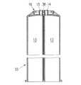
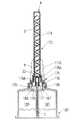
図1及び図2は、混合器1を示し、それには、混合器ハウジング2、混合器素子グループ3、混合器出口4、並びにこの混合器素子グループ3の適正に整列された分離素子3Sと一体である二つの別々の入口部分6および7を備えた混合器入口部5がある。
【0008】
混合器ハウジングは、縦リブ8を備え、それらは、この混合器ハウジング2の大径9で終り、それらの二つの横端は、バヨネットつば10および11に作られていて、カートリッジのバヨネット保持手段と協同する。図2から分るように、これら二つのつばは、同じ幅でなく、つば10がつば11より大きい。後に示すように、つばの幅が違うことが、この混合器をカートリッジにコード整合(coded alignment)を可能にし、決った方向にしか取付かないようにする。
【0009】
この混合器は、混合器の幅の異なるバヨネットつば10、11を幅の異なるバヨネットソケット19、20に合わせて、混合器をカートリッジに押付けながら混合器ハウジング2を回転することによってカートリッジに取付け、別々の入口部分6および7、並びに分離素子3Sを備える混合器素子グループ3は、回転しない。分離素子3Sは、この実施例では、各化学成分を混合器素子グループ3の第1仕切り素子3Dに別々に案内するための分離手段として作用する。
【0010】
図3のカートリッジ12には、二つの円筒形容器13があり、それらは、調量比1:1にするために断面積が等しく、二つの別々の円筒形で離れた出口14および15で終る。このカートリッジの離れた出口14および15の外側形状は、混合器1の別々の入口6および7(図1参照)のそれぞれの内側形状に対応し、それで混合器のこれらの入口がカートリッジの出口の上に嵌まってしっかりした密封結合をする。入口部分6および7が出口開口部14および15の中に嵌り込む、逆の配列も可能である。
【0011】
図4で、カートリッジに付いているバヨネット手段16には、二つの内部くぼみ18を備えたリング形バヨネットソケット17、並びに二つの直径上で対向する異なる幅のバヨネット切り欠き19および20を備えた円形開口部があって、混合器の対応して幅の異なるバヨネットつば10および11(図1参照)を受け、混合器を所定の一方向にだけ符号による挿入をできるようにする。これらの切り欠きに隣接するフランジ部21は、混合器のつばを固着するバヨネット保持手段として作用する。
【0012】
このリング形バヨネット手段は、特に、分配中、取付けた混合器から伝達される液圧が最大であるとき、このバヨネット保持手段の強度を増し、カートリッジの出口端の構造的剛性を増す。この装置は、従来技術の差込尖端に比べてかなりの改善である。
【0013】
図5および図6は、混合器が、カートリッジの雌出口の中に嵌り込んで密封する雄入口部分を備えた、更なる実施例を示す。
【0014】
図5は、混合器101の入口端の図であり、二つの別々の雄入口104および105を含む混合器入口部を備え、それに分離手段が続く混合器ハウジング102がある。この混合器も、混合器のコード手段をカートリッジのコード手段に合わせて、混合器をカートリッジに押付け、混合器ハウジングを内部の一体の混合器部品の周りに回転することによって、カートリッジに取付ける。この混合器ハウジングは、縦リブを備え、それらは、大径106で終り、それらの二つの横端は、バヨネットつば107および108に作られていて、カートリッジのバヨネット保持手段と協同する。これら二つのつばの幅は、同じでなく、つば107の方が大きい。
【0015】
カートリッジ109(図6)には、混合器の雄入口104および105の上に嵌って密封する、離れた出口112および113を備えた二つの円筒形容器110および111がある。このカートリッジ前面114は、図4のカートリッジと同じバヨネット手段16を備え、リング形バヨネットソケットを含んでいる。
【0016】
図7及び図8は、混合器が、カートリッジの雌/雄出口の中に/上に嵌って密封する雄および雌入口部分を備えた、更なる実施例を示す。
【0017】
図7は、混合器115を示し、出口および別の雄入口118と別の雌入口119を含む混合器入口部を備えた混合器ハウジングがある。この混合器も、混合器をカートリッジに押付け、混合器ハウジング116を、別の雄/雌入口118および119を含む内部の一体の混合器部品の周りに回転することによって、カートリッジに取付ける。この混合器ハウジングは、縦リブを備え、それらは、大径で終り、それらの二つの横端は、バヨネットつば121および122に作られていて、カートリッジのバヨネット保持手段と協同する。これらのつばの幅は、同じでなく、つば122の方が大きい。
【0018】
カートリッジ123には、それぞれ、混合器の別の雌入口119の中におよび別の雄入口118の上に嵌って密封する、一つの離れた雄出口126および一つの離れた雌出口127を備えた二つの円筒形容器124および125がある。このカートリッジ前面128(図8)は、図4のカートリッジと同じバヨネット手段16を備え、リング形バヨネットソケットを含んでいる。
【0019】
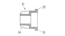
図9および図10は、更なる実施例として混合器25を示し、それには、混合器ハウジング26、混合器素子グループ3、混合器出口4、混合器入口部27がある。この混合器は、別の結合リング31(図13および図14参照)の支援で、カートリッジ35(図11参照)に固定する。この結合リング31は、カートリッジのバヨネット取付け手段16のバヨネット切り欠き19、20にそれぞれ対応する、幅の異なる二つのバヨネットつば32および33、並びに、手でつかみやすくするために、円筒形外面上にリブ34を備える。
【0020】
特に図9から、この混合器入口部27に、第1混合器素子3Sの入口側面に、二つの円筒形の個々の入口開口部28、29があることになり、この第1混合器素子3Sは、この実施例では、各成分を混合器素子グループ3の第1仕切り素子3Dに別々に案内するための分離手段として作用する。スロット30は、この混合器をカートリッジに関してコードによる整列ができるようにする。
【0021】
カートリッジ35(図11および図12参照)は、バヨネット取付け手段の底に、混合器のコードによる整列をするために、混合器のスロット30(図9参照)に対応する突起片36があることを除いて、図1のカートリッジ1と同じである。
【0022】
この混合器をカートリッジに結合するとき、カートリッジ上の突起片36が、混合器入口部27のスロット30に嵌る。このコードによる結合方法は、一つの整列しか可能でなくするだけでなく、混合器ハウジングを回転することなく混合器を軸方向に取付けられるようにする。
【0023】
付属品を分配装置またはカートリッジにコードにより整合するために、この分配装置またはカートリッジにおよび付属品に設けることができるその他のコード手段、例えば、くぼみ、空洞またはスロットに嵌り込むピンまたはあらゆる種類の突出部品、がある。
【0024】
図15は、先の実施例の変形として、断面積が異なる容器76および77を有するカートリッジ75に取付けた混合器38を示し、混合器38の混合器入口部37には、この混合器内に断面積が異なる別々の入口室、それぞれ39、40を含み、カートリッジ出口より小さな総合直径の中に収容され、通過する材料のために各室に対応する開口部を備えた分離手段がある。
【0025】
前記の分離手段は、混合器素子グループ3の第1仕切り素子3Dまで流れる材料の分離を維持する役割をする。この分離手段は、室の断面積が等しくても良く、または断面積比が1:1以外でもよい。例えば、これらの分離室の断面積比をその調量比に対するカートリッジ75の容器76および77の断面積にすることができる。この分離手段は、混合器素子グループ3に固定結合する。
【0026】
図16から図21による本発明の更なる実施例には、カートリッジ42にスナップ嵌めして永久的に取付けた締付けリング51がある。このカートリッジ42には、断面積が等しい二つの円筒形容器43、二つの離れた出口45および46、並びに締付けリングを取付け、その回転運動を制限する取付け手段47がある。この取付け手段47は、同じ幅の二つのつば44を備え、二つの離れた出口の周りに配置され、その基部に円形切下げ48がある円形縁の形をしている。
【0027】
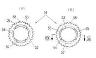
締付けリング51(図18(A)、図18(B)および図19参照)は、カートリッジの取付け手段の円形縁49にスナップ嵌されて、それに取付けられたままである。この締付けリング51には、内円形溝52があって、カートリッジ側の縁53および混合器側の縁54を形成する。カートリッジ側の縁53には、幅がカートリッジ取付け手段のつば44に対応する二つの対向する切り欠き55があり、このカートリッジ側の縁53の内径は、カートリッジ取付け手段の外径よりわずかに小さい。この締付けリングをカートリッジにスナップ嵌めするためには、このリングをそのカートリッジ側の縁の切り欠きが取付け手段のつばの上に来るように置き、次にこのリングをカートリッジに押付けて、締付けリングのカートリッジ側の縁の残りが取付け手段の円形切下げ48に滑り込むようにする。この締付けリングは、手でつかみやすくするためにセレーション58も備えている。
【0028】
混合器側の縁54には、一つの方向にしか入らないようにするために、混合器のつば10および11に対応する幅の異なる二つの対向する切り欠き56および57がある。これら二つの切り欠きは、カートリッジ側の縁の切り欠き55と90°に配置されている。それで、混合器59をカートリッジ上の締付けリングに取付けるべきとき、この締付けリングを90°だけ回転すると、カートリッジ側の縁と混合器側の縁の両方の残りの内側フランジ部分が、カートリッジの取付け手段47のつば44は勿論、混合器のつば10および11を取り囲むバヨネット保持手段として作用して、強く固着する。
【0029】
図20および図21は、混合器59を付けた、図16のカートリッジ42を示し、その混合器は、ハウジング60が混合器の一体の内部部品の周りに回転できず且つリブ8がなく、二つのバヨネットつば10および11の幅が異なることを除いて、図1の混合器1に類似し、別々の雌入口6および7のある同じ入口部5を備えている。図20は、この混合器を締付けリング51に挿入し、この締付けリングがその締付け位置にある図を示し、図21は、図20の線XXI−XXIによ
る同じ組立体の90°回転した断面を示す。別々の入口室を備える混合器を同様に取付けることができること、およびカートリッジは、断面積が異なる容器を有するものでもよいことが明白である。
【0030】
上に説明した、混合器をコード取付けするシステムは、キャップ、アダプタ等のコード取付けも可能にし、それによって相互汚染を防ぎ、キャップの再利用を可能にする。使用するキャップの取付け部は、混合器の取付け部に類似し、カートリッジの出口および取付け部にコード態様で嵌める。
【0031】
図22から図24は、図1から図4による混合器およびカートリッジのバヨネット装置に比べて逆のバヨネット装置を備えた、本発明の更なる実施例を示す。図22は、混合器出口4を備える混合器ハウジング81並びに上記の部品および分離手段を含む混合器入口部82がある混合器80を示す。この混合器も、混合器とカートリッジのコード手段を合わせて、混合器をカートリッジに押付け、この混合器の混合器ハウジング81を、別々の雌入口83および84、分離素子3S並びに混合器素子グループ3を含む、内部の一体の混合器部品の周りに回転することによって、カートリッジに取付ける。この混合器素子グループまたはその部品は、混合器ハウジング内に予備整合し、固定して組付けてもよい。
【0032】
混合器ハウジング81は、大径85で終る縦リブ8を備えている。この混合器ハウジングの大径端には、突起片89があって、それがこのカートリッジのスロット付尖端90に整合し挿入するためのよく見えるコード案内となる。この混合器ハウジング81は、バヨネット保持手段として作用し、間に二つの切り欠き96および97がある、二つのバヨネットフランジ部94および95を含むリング形バヨネットソケット取付け手段100も備える。
【0033】
カートリッジ86には、混合器入口部82に嵌って密封するための離れた出口14および15を備えた、二つの円筒形容器87および88がある。カートリッジ前面86Aは、混合器の間違った挿入を防ぐために、スロット付尖端90および案内片91を備え、更に、幅が混合器の切り欠き96および97に対応し、間に直径の小さい切り欠き98および99がある、テーパ付楔形縁の二つのバヨネットフランジ92および93も備える。
【0034】
この混合器をカートリッジに取付けるためには、混合器入口をカートリッジの離れた雄出口14および15の上に押付けるとき、部分91が案内片として作用している間に、混合器ハウジングの突起片89をスロット付尖端90内に整合することによって、混合器入口部82をカートリッジに挿入し、カートリッジフランジ92および93が混合器切り欠き96および97と一致し、その中に入るようにする。混合器ハウジングを回転すると、混合器バヨネットフランジ部94および95は、カートリッジフランジ92および93が深さ方向にテーパ付楔形であって、混合器80をカートリッジ前面86Aに押付けるので、次第にカートリッジフランジに抗して動く。この混合器をカートリッジに取付ける間、混合器ハウジング81は、静止した内部の一体の混合器部品の周りに90°回転する。
【0035】
リング形バヨネットソケットが、回転混合器ハウジングで図示したように、付属品側にある、上記のバヨネット装置は、締付けリングの解決法を除いて、先に示した実施例にも、およびキャップにも、類似の方法で使うことができる。混合器ハウジングの外周に代替コード手段を配置することは、可能または切り欠きの幅および係合するフランジ部品を違えることによって達成できる。
【0036】
図25から図31の実施例は、完全なリング形ではなくて扇形のバヨネットソケットを示す。この付属品の機能および取付けは、先の実施例と同じであり、それでこのバヨネット手段の三つの異なる実施例を混合器とカートリッジのそれぞれの一つの例で説明する。この扇形バヨネットソケットおよび類似の手段を他の全ての実施例にも設けることができることは明白である。
【0037】
混合器130の混合器ハウジングは、二つの横端を備え、それらはバヨネットつば136および137として形成され、図25のカートリッジ138のバヨネット保持手段として作用する扇形バヨネットソケット145、146と協同する。これらのバヨネットつばは、幅が同じで、各々その端にリブ136Aおよび137Aを備え、それらが各つばを補強すると共にストッパとして作用し、並びにこの混合器を一方向にだけ回転して取付けられることを保証する。これらのつばの上面は、軸方向負荷による締付け能力を強化するように傾斜した表面部品を有してもよい。対応する傾斜した表面部品を、このカートリッジ扇形バヨネットソケットの対応する面にも配置してもよい。
【0038】
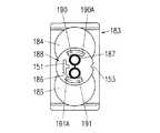
図25のカートリッジ138には、別々の雄入口133および134を受け、密封するための二つの離れた雌出口141および142を備えた二つの円筒形容器139および140がある。カートリッジ前面143(図25)は、扇形バヨネットソケット145、146を含むバヨネット手段を備え、それらのバヨネットソケットは、尖端として作用し、片側がリブ145Aおよび146Aによって閉ざされ、そのリブがこのカートリッジ端壁と結合してこのバヨネット尖端を硬化し強度を増す。扇形バヨネットソケットの間の切り欠き149および150は、混合器バヨネットつば136および137を挿入できるようにする。
【0039】
この実施例では、バヨネットつばと扇形バヨネットソケットがほぼ同じ幅である。コード化は、混合器とカートリッジで別のコード化手段によって行う。カートリッジ前面143は、二つの出口の間に配置されたT形突起151を備え、混合器入口面は、混合器入口の間に中心を外して配置された同様な突起152を備える(図25および図26参照)。
【0040】
これら二つのT形コード化手段は、これら二つの突起を互いに重なるように置くと、それらが混合器入口をカートリッジ出口に挿入できなくし、カートリッジ出口と混合器入口または閉鎖手段の栓の間の接触も防ぐので、混合器を一方向にしか取付けられなくし、それによって相互汚染を防ぎ、混合器/付属品の取付けを禁止する。これらのコード化突起がT形以外の他の形状をとることができること、および、例えば、キー溝の形をしていて、一つの決った位置でだけ対応する突起を持った混合器を挿入できるようにするか、または二つの異なる形状のキー溝と対応する突起でもよいことは明らかである。
【0041】
このコードによる整列は、目に見えるコード手段、例えばカートリッジ出口端に印153を付け、混合器のバヨネットつば137のコード突起と同じ側に印154を付けることによって、容易にすることができる。
【0042】
図27から図28(B)の実施例では、このコード付けをバヨネットつば間の幅の異なる切り欠きによって達成する。図28(B)の混合器155の混合器ハウジングは、大径で終る縦リブを備え、その二つの横端は、バヨネットつば160および161に作られていて、カートリッジの扇形バヨネット保持手段と協同する。
【0043】
これらのバヨネットつば160、161は、各々混合器入口の反対側にリブ167(図28(A))を設けることができ、それが混合器を正しい整合と180°に取付けることを防ぐように一方向にしか回転できなくすることは勿論、つばを補強すると共にストッパとして作用する。これらのつばの上面は、軸方向力によって締付け能力および封止能力を強化するように傾斜した部品(図示せず)を有してもよい。対応する傾斜した表面部品(図示せず)を、このカートリッジ扇形バヨネットソケットの対応する面にも配置してもよい。
【0044】
カートリッジ162には、別々の雄入口157および158を受け、密封するための二つの離れた雌出口165および166を備えた二つの円筒形容器163および164がある。カートリッジ前面168(図27)は、二つの扇形バヨネットソケットを含むバヨネット手段を備えている。
【0045】
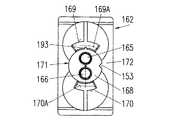
図27で、カートリッジのバヨネット手段には、混合器のバヨネットつばに対するバヨネット尖端として作用する直径上で対向する二つの扇形バヨネットソケット169および170があり、これら二つのソケットの幅は異なり、ソケット169の幅の方が大きい。ソケット間の二つの切り欠き171および172は、対応する混合器バヨネットつば160および161を扇形バヨネットソケット169、170に挿入できるようにする。この図に示すように、バヨネットソケット169および170の通路は、直線通路に始るが、中間点から先は曲って、バヨネットつばの軸方向力に対する強度が大きくなる。
【0046】
これらの通路は、直線部分がなく、全体が曲っていても良く、また全体的にまたは部分的に曲った通路をリング形バヨネット取付け手段上に設けることもできる。
【0047】
混合器の入口とカートリッジの出口が間違った整合をしている間に、それらの一つが他に対して何らかの形で傾くことによって、それらが不用意に接触することを避けるために、大きい方のソケット169のV形切れ目193に対応するV形突起192を、混合器の大きな切り欠き195に設け、混合器が狭い方のソケット170の上を滑るのをこのV形突起192によって防ぐ。
【0048】
この実施例でも、コードによる整列は、目に見えるコード手段、例えばカートリッジに印153を付け、対応するつばに印154を付けることによって、容易にすることができる。
【0049】
混合器をカートリッジ162に一つの決った方向で取付ける必要がない場合は、混合器のつば間の両切り欠きは、カートリッジの大きい方の保持手段に嵌まるように十分大きくなければならず、一方可視コード手段は、先に説明したのと同じままである。
【0050】
混合器155には、二つの直径拡張部があり、例えば、一つは入口にあって別々の入口157、158を収容し、密封する第1部分159であり、それに続いて分離手段157A、158Aを収容し、密封する第2部分159Aである。バヨネットつば160、161もリブを有し、同じ幅であるが、それらの間の隙間または切り欠き194、195は、カートリッジの扇形バヨネットソケットの異なる幅に対応して、異なる。
【0051】
図29から図31は、混合器200が結合リング196と別であることを除いて、図27から図28(B)のものに類似する装置であり、結合リングバヨネットつば160A、161Aをカートリッジ162の扇形バヨネットソケット169、170に回転締付け取付けするときに、結合リングを静止している混合器の周りに回転する。
【0052】
図29は、組立たときの混合器200およびカートリッジ162を示す。それは、混合器200に、入口部197と整合した混合器素子グループ3を含むハウジング201があり、この入口部は、部分的にしか混合器ハウジングに含まれず、別々の雄入口157B、158Bおよび別々の室157C、158Cを含むことを示す。隆起198が入口部197を混合器ハウジング内に収容し、密封する。結合リング196は、予備組立され、この結合リング196の溝199(図30(A))を介して混合器入口部197と予備整合されている。図30(B)は、図28(A)による実施例で使用したのと同じコード付けされたバヨネットつば160A、161A、切り欠き194A、195A、可視コード154AおよびV形突起コード192Aを備えた結合リング196を示す。
【0053】
そのような組立の前に、結合リング196は、十分な張力を加えて混合器に予備組立して、両部品が、初期のコードによる目で見たおよび初期のコードによる軸方向の機械的接触に対して正しい相対整合で、上記のように結合リングを最終的に回転締付け取付けする前に、混合器入口157B、158Bをこのカートリッジのカートリッジ出口165、166に取付けてまとまっているようにする。従って、この実施例では、取付けるときに混合器ハウジング201を静止した混合器入口部197および素子グループ3の周りに回転しない。
【0054】
図32から図34による実施例では、図22から図24による実施例に類似して、扇形バヨネットソケットが混合器にあり、バヨネットつばがカートリッジにある。
【0055】
図32は、混合器−カートリッジ組立体を示し、混合器173には、出口4を備える混合器ハウジング174および混合器入口部175があり、その入口部は、内部の一体の部品を含み、それらには、二つの別々の入口176および177に続き別々の室176Aおよび177Aがあり、次にそれらの室は、混合器素子グループ3の第1仕切り素子3Dに固定して取付けられている。この混合器も、混合器をカートリッジに押付け、混合器ハウジング174を別々の雄入口176および177、別々の室176Aおよび177A並びに混合器素子グループ3の周りに回転することによって、カートリッジに取付ける。この混合器素子グループまたはその部品も、予備整合して、この混合器ハウジングの中に固定するように組立てもよい。
【0056】
この混合器では、混合器ハウジングの入口端に、一つだけではなく二つの円筒形拡張部があり、例えば、一つは入口にあって別々の入口176、177を収容し、密封する第1部分178であり、それに続いて分離手段176A、177Aを収容し、密封する中間直径の第2部分178Aであることを示す。
【0057】
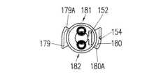
混合器ハウジング174は、大径178で終る縦リブ8を備え、その二つの横端は、尖端として作用する直径上で対向する二つの扇形バヨネットソケット179および180(図34参照)に作られていて、それらは共に片側がリブ179Aおよび180Aによって閉ざされ、そのリブがこの混合器壁と結合してこのバヨネット尖端を硬化し強度を増す。ソケットの間の切り欠き181および182は、混合器のバヨネット保持手段と協同するカートリッジバヨネットつばを挿入できるようにする。
【0058】
図33のカートリッジ183には、別々の雄入口176および177の上に嵌って密封する、二つの離れた雌出口186および187を備えた二つの円筒形容器184および185がある。このカートリッジ前面188は、同じ幅の扇形バヨネットつば190および191を含むバヨネット手段を備え、これらのつばは、各々その端にリブ190Aおよび191Aを備え、それが混合器を正しい整合と180°に取付けることを防ぐように一方向にしか回転できなくすることは勿論、つばを補強すると共にストッパとして作用する。これらのつばの上面は、軸方向負荷によって締付け能力を強化するように傾斜した部品(図示せず)を有してもよい。対応する傾斜した表面部品(図示せず)を、この混合器扇形バヨネットソケットの対応する面にも配置してもよい。
【0059】
これらのつばは、切り欠きのように、幅がほぼ等しい。それで、必要なコード化は、混合器とカートリッジで別のコード化手段によって行う。従って、カートリッジ前面188は、二つの離れた雌出口の間に配置されたT形突起151を備え、混合器入口面は、混合器入口の間に中心を外して配置された類似形状の突起152を備える(図33および図34参照)。
【0060】
これら二つのT形コード化手段は、これら二つの突起が互いに重なるように混合器をカートリッジの上に置くと、それらが混合器の別々の雄入口をカートリッジの離れた雌出口に挿入できなくし、カートリッジ出口と混合器入口の間の接触も防ぐので、混合器を一つの位置でしか取付けられなくし、それによって相互汚染を防ぎ、混合器/付属品の取付けを禁止する。これらのコード化突起がT形以外の他の形状をとることができることは明らかである。
【0061】
片側のT形コード化突起では相互汚染を避けるための100%の保護をしない場合がある。図35から図42に、混合器を間違った方向でカートリッジに挿入しても相互汚染が起きないことを保証する、いくつかのコード化突起を示す。この目的で、コード化突起が、この汚染を起すことになる、カートリッジの二つの出口の中心を結ぶ軸線の周りに傾斜しないように配置されている。
【0062】
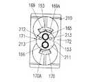
図35のカートリッジ210は、図27のカートリッジ162と類似し、別々の雄入口157および158を受け、密封するための二つの離れた雌出口165および166を備えた同じ二つの円筒形容器がある。カートリッジ前面211は、混合器のバヨネットつばに対するバヨネット尖端として作用する直径上で対向する二つの扇形バヨネットソケット169および170があり、これら二つのソケットの幅は異なり、ソケット169の幅の方が大きい。ソケット間の二つの切り欠き171および172は、対応する混合器バヨネットつば160および161を扇形バヨネットソケット169、170に挿入できるようにする。この図35に示すように、バヨネットソケット169および170の通路は、直線通路に始るが、中間点から先は曲って、バヨネットつばの軸方向力に対する強度が大きくなる。
【0063】
図27のカートリッジとは違って、このカートリッジ210の前面は、出口の中心を結ぶ軸線に対して対象ではあるが横中間軸に関しては非対称に、例えば一つの出口側に、配置された二つのピン213から成るコード化手段212を備えている。
【0064】
図36は、二つの別々の入口157および158に続き分離手段を含む混合器ハウジングを備える混合器214の入口端の図である。この混合器も、混合器をカートリッジに押付け、この混合器ハウジングを内部の一体の混合器部品の周りに回転することによって、カートリッジに取付ける。この混合器ハウジングは、大径で終る縦リブを備え、その二つの横端は、バヨネットつば160および161に作られていて、カートリッジの扇形バヨネット保持手段と協同する。
【0065】
図28(A)の混合器に比べて、この混合器214の入口部は、更に、二つのピン216から成り、カートリッジのピン213に従って配置された、カートリッジ210のものと同じコード化手段215を備え、この混合器を他のコード化手段に関して、もし間違った方向で挿入しても傾ける可能性なしに、正しい方向だけでしか挿入できないようにする。
【0066】
図37から図42は、コード化突起212、215の更なる配置および形状を示し、そこではカートリッジも混合器も常に図35、図36と同じであり、コード化突起だけ数字を備え、他の部品は同じである。
【0067】
図37および図38は、横中間軸に対して対象ではあるが出口の中心を結ぶ軸線に対しては非対称に配置された二つの矩形棒217から成る、カートリッジの前面上のコード化突起212を示す。混合器入口部の二つの棒218は、カートリッジのそれに従って配置され、混合器をカートリッジに挿入し取付けることは、一方向にだけ可能である。
【0068】
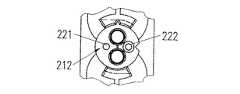
図39および図40は、対象に配置された雄プラグ221と雌レセプタクル222から成る、カートリッジの前面上のコード化突起212を示す。混合器入口部の雄プラグ223と雌レセプタクル224は、カートリッジのそれに従って配置され、混合器をカートリッジに挿入し取付けることは、一方向にだけ可能である。
【0069】
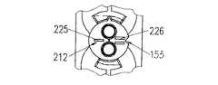
図41および図42は、出口の中心を結ぶ軸線の片側の棒225とこの軸線の他の側の二つの離れた棒226から成り、カートリッジの横中間軸に対して対象に配置された、カートリッジの前面上の特に有効なコード化突起212を示す。混合器入口部の単一棒227と二重棒228は、カートリッジのそれに従って配置され、混合器をカートリッジに挿入し取付けることは、一方向にだけ可能である。
【0070】
これら全てのコード化突起は、他の適当な形状・形態のどれでも良く、混合器を間違った方向に向けても、混合器をカートリッジに取付けるときに傾斜することを効果的に防ぎ、従って相互汚染を防ぐ。
【0071】
このコード整合は、目に見えるコード手段、例えばカートリッジに突起に対向して印153を付け、混合器のつばのコード突起の近くに印154を付けることによって、容易にすることができる。
【0072】
図7および図8の実施例から、混合器の入口とカートリッジの出口は、それぞれ雌でも雄でもよいことになり、混合器に、対応するカートリッジの雄出口/雌出口の上に/中に嵌る一つの雌入口と一つの雄入口を設けることが可能であるということにもなる。
【0073】
この後者の配置は、混合器または閉鎖手段をカートリッジと合わせることができるのは一つの位置だけであるので、更なるコード手段を備える。このコードとコード手段の混合配置は、結合リング、締付けリングまたは回転可能な混合器ハウジングによる取付け方法とは独立である。
【0074】
バヨネットつばの幅を違えることは、はっきりしたコード手段となるが、コードを目に見えるようにすることによってこの効果を高めることが有利かも知れない。この目に見えるようにすることは、例えば、異なる色、切込みおよび印のような光学手段によって、または付属品の切り欠きに突起を設けてカートリッジのバヨネット保持手段に対応する切り欠きを設けることによって行う。これは、コード部品の一つに目に見える印を付けるか、コードそれ自体に対して実施することができる。
【0075】
例えば、米国特許第5,333,760号による、単一壁により分離したカートリッジは、そのような単一壁の分離遮断層を通る化学的移行を排除できず、従って、カートリッジ出口での分離では、移行、従って保管中のシリンダ内の反応を防ぐには十分でない。
【0076】
特に、図16および図22から、間をエアギャップLで実質的に分離した、二つの完全な、好ましくは円筒形の容器から成る一体のカートリッジを設けることが有利であるということになる(図16参照)。これは、シリンダピストンの前から、保管中は閉鎖手段が装着されている出口の上まで、化学製品が入っている全長に亘って、完全な化学的分離を保証する。分配中、この分離は、更に混合器内で混合器素子グループの第1仕切り素子3Dまで維持される。
【0077】
しかし、この発明は、エアギャップで分離した容器に限定されず、図3による単一壁で分離された容器を備えるカートリッジにも同様に適用する。
【0078】
上記の説明から、この独創的カートリッジと付属品連結装置の組合せは、特に個々の出口までエアギャップによって分離されたカートリッジ容器に対して、および大きさが同じまたは異なる口に対する口と口のコード整合に対して、境界面を通る化学成分の分離を混合器の中まで十分に維持し、この境界面でおよびカートリッジ出口まで逆行して起り得る化学成分の反応および詰りが広がるのを防ぎながら、回転またはでたらめな取付けによる相互汚染が生じないようにする。この組合せはまた、それだけではないが、特に1:1以外の比に対して混合性能を最適化する。
【0079】
これらのカートリッジ実施例の前記の説明および図面は、並列容器を備えた多成分カートリッジに関連するが、この発明の教示は、それに限定されず、同心の容器または他の方法で配置・形成された容器を備えるカートリッジにも同様に適用できる。
【0080】
しかし、このコードによる取付けの原理は、混合器または付属品を一方向にしかできないので、混合器または付属品をカートリッジ出口に正しく整合して結合することと、混合器またはキャップをカートリッジに再結合する場合は、相互汚染をなくすることの両方を保証する。
【0081】
その上、混合器に関しては、混合器入口、分離手段および混合器素子グループを一体に作るので、上に説明した実施例は全て、最少数の部品しか含まず、コンパクトであり、その結果成形および組立てコストが安いという利点を有する。また、この内部部品の一体構成は、適正整合を保証し、従って混合効率を最適にする。
【0082】
図1による第1実施例の場合で、比較的長い混合器素子グループを使い、この混合器素子グループと混合器ハウジングの間の回転摩擦が問題を起す虞があるときは、混合器素子グループの一部または全部を入口部の分離手段から分離し、この混合器素子グループの一部または全部をハウジングの中に固定して組立て適正に整合し、従って、混合器をカートリッジに結合しながら、それがハウジングと共に回転するようにするのが好ましいかも知れない。
【0083】
この場合、混合器入口から混合器出口の方に見て、混合器素子グループの第1素子、またはその一部の前端は、ハウジングの中で予備整合した位置に固定して組立てねばならない。従って、混合器をカートリッジに取付けるためにハウジングを回転してから、これらの素子の正しい整合が得られ、分離手段またはこの分離手段に取付けられた第1素子グループを出た二つの材料流が、この素子グループまたはハウジングに取付けられたその一部の第1素子の前端によって均等に分割され、最適の混合効率が得られる。
【0084】
円筒形の入口および出口ではなく、D形または異形で、大きさが類似または異なる入口および出口が可能であることは明白である。更に、同じ原理を、3成分以上の分配装置、またはカートリッジにも使える。
【図面の簡単な説明】
【図1】回転可能な混合器ハウジングを備えた、この発明の第1実施例の混合器の縦断面図である。
【図2】この第1実施例の混合器の入口端を示す図である。
【図3】この第1実施例のカートリッジの縦断面図である。
【図4】離れた出口およびリング形バヨネット手段を備えた、図3のカートリッジの平面図である。
【図5】第1実施例の変形の混合器の入口端を示す図である。
【図6】第1実施例の変形のカートリッジの平面図である。
【図7】第1実施例に対する更なる変形の混合器の入口端を示す図である。
【図8】第1実施例に対する更なる変形のカートリッジの平面図である。
【図9】結合リングを含む、この発明の第2実施例の混合器の縦断面図である。
【図10】この第2実施例の混合器の入口端を示す図である。
【図11】離れた出口およびリング形バヨネット手段を備えた、第2実施例のカートリッジの平面図である。
【図12】突起片を備えた、図11のカートリッジの平面図である。
【図13】第2実施例の結合リングの平面図である。
【図14】図13の結合リングの断面図である。
【図15】断面積が異なる容器を有する、図3および図4のカートリッジに取付けた図1の混合器の変形の縦断面図である。
【図16】カートリッジに永久的に取付けた締付けリングを備えた、この発明の第3実施例の、離れた出口を備えたカートリッジの縦断面図である。
【図17】図16のカートリッジの平面図である。
【図18】(A)は、第3実施例のカートリッジに取付けるべき締付けリングの混合器側の図である。(B)は、図18(A)の締付けリングのカートリッジ側の図である。
【図19】図18(B)の線IXX −IXX による締付けリングの断面図である。
【図20】図18(A)ないし図19の締付けリングで図16のカートリッジに取付けた混合器の、締付け位置での断面図である。
【図21】図20の線XXI −XXI による同じ組立体の90°回転した断面図である。
【図22】回転可能な混合器ハウジングにリング形バヨネットソケットを備えた、この発明の代替実施例の、部分的に示すカートリッジに取付けた混合器の縦断面図である。
【図23】図22の混合器の入口端を示す図である。
【図24】図22のカートリッジの平面図である。
【図25】カートリッジに扇形バヨネットソケットを備えた、この発明の更なる実施例のカートリッジの平面図である。
【図26】カートリッジに扇形バヨネットソケットを備えた、この発明の更なる実施例の混合器の入口端を示す図である。
【図27】カートリッジに扇形バヨネットソケットを備えた、この発明の代替実施例のカートリッジの平面図である。
【図28】(A)は、カートリッジに扇形バヨネットソケットを備えた、この発明の代替実施例の混合器の入口端を示す図である。(B)は、図28(A)の混合器の一部の縦断面図である。
【図29】結合リングを備えた、この発明の更なる実施例の、部分的に示すカートリッジに取付けた混合器の縦断面図である。
【図30】(A)は、図29の結合リングの縦断面図である。(B)は、図29の結合リングの平面図である。
【図31】図29の混合器の一部の縦断面図である。
【図32】扇形バヨネットソケットを備えた、この発明の更なる実施例の、部分的に示すカートリッジに取付けた混合器の縦断面図である。
【図33】図32のカートリッジの平面図である。
【図34】図32の混合器の入口端を示す図である。
【図35】混合器を間違ってカートリッジに取付けることによる相互汚染を防ぐための、カートリッジと混合器の両方の更なるコード手段の内、図27に類似するカートリッジにコード手段を付加したものの平面図である。
【図36】図35のカートリッジに対応する混合器の入口端を示す図である。
【図37】カートリッジのコード手段の変形を示す。
【図38】図37のカートリッジに対応する混合器の入口端を示す。
【図39】カートリッジのコード手段の更なる変形を示す。
【図40】図39のカートリッジに対応する混合器の入口端を示す。
【図41】カートリッジのコード手段の更なる変形を示す。
【図42】図41のカートリッジに対応する混合器の入口端を示す。
【符号の説明】
1 付属品(混合器)
2 ハウジング
3 混合器素子グループ
3D 第1分割素子
3S 分離手段(第1素子)
5 入口部
6 混合器雌入口
7 混合器雌入口
10 つば
11 つば
12 カートリッジ
13 容器
14 雄出口
15 雄出口
16 バヨネット取付け手段
17 リング形バヨネットソケット
18 内部くぼみ
19 切り欠き
20 切り欠き
21 バヨネット保持手段
22 容器
23 容器
24 カートリッジ
25 付属品(混合器)
26 ハウジング
27 入口部
28 混合器入口
29 混合器入口
30 スロット
31 結合リング
32 つば
33 つば
35 カートリッジ
37 入口部
38 付属品(混合器)
39 分離手段(室)
40 分離手段(室)
42 カートリッジ
43 容器
45 雄出口
46 雄出口
47 取付け手段
51 バヨネット取付け手段(締付けリング)
52 円形溝
55 切り欠き
56 切り欠き
57 切り欠き
59 付属品(混合器)
60 ハウジング
61 付属品
64 つば
65 つば
67 付属品
69 スロット
71 付属品
73 つば
74 つば
75 カートリッジ
76 容器
77 容器
80 付属品(混合器)
81 ハウジング
82 入口部
83 混合器雌入口
84 混合器雌入口
86 カートリッジ
87 容器
88 容器
89 突起片
90 プロング
92 つば
93 つば
94 バヨネット保持手段
95 バヨネット保持手段
96 切り欠き
97 切り欠き
98 切り欠き
99 切り欠き
100 バヨネット取付け手段
101 付属品
102 ハウジング
104 混合器入口
105 混合器入口
107 つば
108 つば
109 カートリッジ
112 雌出口
113 雌出口
115 混合器
116 ハウジング
118 混合器雄入口
117A 室
117B 室
119 混合器雌入口
123 カートリッジ
126 雄出口
127 雌出口
130 付属品(混合器)
131 ハウジング
133 混合器雄入口
133A 分離手段(室)
134 混合器雄入口
134A 分離手段
134B 室
136 つば
137 つば
138 カートリッジ
139 容器
140 容器
141 雌出口
142 雌出口
143 カートリッジ前面
145 扇形バヨネットソケット
145A リブ
146 扇形バヨネットソケット
146A リブ
149 切り欠き
150 切り欠き
151 コード突起
152 コード突起
153 印
154 目に見える印
155 付属品(混合器)
156 ハウジング(混合器管)
157 混合器雄入口
157A 分離手段(室)
158 混合器雄入口
158A 分離手段(室)
159A 中間部
160 つば
160A つば
161 つば
161A つば
162 カートリッジ
163 容器
164 容器
165 雌出口
166 雌出口
169 扇形バヨネットソケット
169A 湾曲部
170 扇形バヨネットソケット
170A 湾曲部
171 切り欠き
172 切り欠き
173 付属品(混合器)
174 ハウジング
176 混合器雄入口
176A 分離手段(室)
177 混合器雄入口
177A 分離手段(室)
179 つば(バヨネットソケット保持手段)
179A リブ
180 つば(バヨネットソケット保持手段)
180A リブ
181 切り欠き
182 切り欠き
183 カートリッジ
184 容器
185 容器
186 雌出口
187 雌出口
188 カートリッジ前面
190 つば
191 つば
192 コード突起
193 切れ目
195 切り欠き
200 付属品
210 カートリッジ
212 コード突起
213 突起
214 付属品
215 コード突起
216 突起
217 突起
218 突起
219 突起
220 突起
221 突起
222 突起
223 突起
224 突起
225 突起
226 突起
227 突起
228 突起
L エアギャップ[0001]
BACKGROUND OF THE INVENTION
The invention relates to a bayonet fixing device according to the preamble of claim 1 or claim 2 for the correct attachment of accessories to a dispensing device, in particular for the attachment of a mixer to a two-component cartridge.
[0002]
[Prior art]
Having means for attaching the mixer to the cartridge, for example according to U.S. Pat. No. 4,767,026 or U.S. Pat. No. 4,538,920, rotating the two bayonet clamping collars of the mixer to the corresponding cartridge There are a number of mixers and cartridges that insert into the prong. On the other hand, rotational clamping movement of the entire mixer will cause one chemical component to contaminate other chemical components at the interface between the cartridge and the mixer. That is, these components are each carried from one outlet to the other and from one inlet to the other, preferably between these chemical components at the interface between the cartridge and the mixer or closure means. Will result in no reaction, eventually returning such a reaction back into the cartridge outlet, thereby clogging the outlet. On the other hand, for example, when the cartridge outlet or mixer inlet is different in size due to a different relative mixing ratio, or when the mixer or accessory is remounted for reuse, the mixer or accessory It may be necessary to couple and attach the item to the multi-component cartridge or dispenser in a predetermined direction.
[0003]
A clean mixer or accessory inlet area or closure plug can be angled, eg, angularly, with chemical components at the cartridge outlet area during the initial placement of the mixer or closure plug relative to the cartridge in preparation for installation. Thus, another form of cross-contamination can occur when making some form of misaligned contact. In that case, the cartridge outlet can be chemically contaminated when the same mixer or closure plug is fitted in the wrong direction. This can also clog and return the reaction back into the cartridge outlet.
[0004]
[Problems to be solved by the invention]
Based on this prior art, it is an object of the present invention to provide a bayonet attachment means in which the alignment of the accessory inlet with respect to the cartridge outlet is performed only in one fixed direction to avoid cross-contamination.
[0005]
Finally, all prior art bayonet attachment means commonly have a relatively small bayonet tip in the cartridge, thus limiting structural rigidity and strength. This tends to cause deflection and distortion and reduces the diameter of the mixer, thus increasing the back pressure, resulting in a tendency to leak at the mixer / cartridge sealing interface during dispensing. Very important. Accordingly, a further object of the present invention is to improve strength against stress and structural rigidity.
[0006]
[Means for Solving the Problems]
The first object of the invention is achieved with a device according to independent claim 1, and the second object is achieved with a device according to
[0007]
DETAILED DESCRIPTION OF THE INVENTION
Hereinafter, the present invention will be described in more detail with reference to the drawings of embodiments.
1 and 2 show a mixer 1, which is integrated with a
[0008]
The mixer housing comprises
[0009]
This mixer is attached to the cartridge by rotating the
[0010]
The
[0011]
In FIG. 4, the bayonet means 16 attached to the cartridge comprises a ring-
[0012]
This ring bayonet means increases the strength of the bayonet retaining means and increases the structural rigidity of the outlet end of the cartridge, particularly when the hydraulic pressure transmitted from the installed mixer is maximum during dispensing. This device is a significant improvement over prior art plug tips.
[0013]
FIGS. 5 and 6 show a further embodiment in which the mixer comprises a male inlet portion that fits and seals into the female outlet of the cartridge.
[0014]
FIG. 5 is a view of the inlet end of the
[0015]
The cartridge 109 (FIG. 6) has two
[0016]
Figures 7 and 8 show a further embodiment in which the mixer comprises a male and female inlet portion that fits into and over the female / male outlet of the cartridge.
[0017]
FIG. 7 shows the
[0018]
[0019]
FIGS. 9 and 10 show a
[0020]
In particular, from FIG. 9, this
[0021]
The cartridge 35 (see FIGS. 11 and 12) has a
[0022]
When this mixer is coupled to the cartridge, the protruding
[0023]
Other cord means that can be provided on the dispensing device or cartridge and on the accessory to code the accessory to the dispensing device or cartridge, such as a pin or any type of protrusion that fits into a recess, cavity or slot There are parts.
[0024]
FIG. 15 shows, as a modification of the previous embodiment, a
[0025]
The separation means serves to maintain separation of the material flowing to the
[0026]
A further embodiment of the present invention according to FIGS. 16-21 includes a clamping
[0027]
The clamping ring 51 (see FIGS. 18A, 18B and 19) is snapped onto the
[0028]
On the
[0029]
FIGS. 20 and 21 show the
Figure 2 shows a section of the same assembly rotated 90 °. It will be apparent that mixers with separate inlet chambers can be similarly installed and that the cartridge may have containers with different cross-sectional areas.
[0030]
The mixer cording system described above also allows cording of caps, adapters, etc., thereby preventing cross-contamination and allowing cap reuse. The cap attachment used is similar to the mixer attachment and is fitted in a cord fashion to the outlet and attachment of the cartridge.
[0031]
FIGS. 22 to 24 show a further embodiment of the invention with a reverse bayonet device compared to the mixer and cartridge bayonet device according to FIGS. FIG. 22 shows a
[0032]
The
[0033]
The
[0034]
In order to attach the mixer to the cartridge, when the mixer inlet is pushed over the remote
[0035]
The bayonet device described above, with the ring-shaped bayonet socket on the accessory side as illustrated in the rotary mixer housing, can be used in the embodiments and caps shown above, except for the clamping ring solution. Can be used in a similar way. Placing alternative cord means on the outer periphery of the mixer housing can be achieved or can be accomplished by varying the notch width and engaging flange parts.
[0036]
The embodiment of FIGS. 25-31 shows a fan-shaped bayonet socket rather than a perfect ring. The function and attachment of this accessory is the same as the previous embodiment, so three different embodiments of this bayonet means will be described with one example of each of the mixer and cartridge. It will be apparent that this sector bayonet socket and similar means can be provided in all other embodiments.
[0037]
The mixer housing of the
[0038]
The
[0039]
In this embodiment, the bayonet collar and the fan-shaped bayonet socket are approximately the same width. The encoding is performed by separate encoding means for the mixer and the cartridge. The
[0040]
These two T-shaped coding means, when these two protrusions are placed so as to overlap each other, they prevent the mixer inlet from being inserted into the cartridge outlet, and the contact between the cartridge outlet and the mixer inlet or closure means plug This also prevents the mixer from being installed in one direction, thereby preventing cross-contamination and prohibiting mixer / accessory installation. These coded projections can take other shapes besides T-shape and, for example, in the form of a keyway, a mixer can be inserted with a corresponding projection only at one fixed position Obviously, there may be two differently shaped keyways and corresponding protrusions.
[0041]
This cord alignment can be facilitated by marking 153 on the visible cord means, for example, the cartridge outlet end, and marking 154 on the same side as the cord protrusion of the
[0042]
In the embodiment of FIGS. 27-28B, this coding is achieved by notches with different widths between bayonet collars. The mixer housing of the
[0043]
Each of these
[0044]
[0045]
In FIG. 27, the bayonet means of the cartridge has two diametrically opposed
[0046]
These passages have no straight portions and may be entirely bent, or they may be provided on the ring-shaped bayonet mounting means in whole or in part.
[0047]
While the mixer inlet and cartridge outlet are misaligned, the larger one is used to avoid inadvertent contact of one of them in some way with respect to the other. A V-shaped
[0048]
Again in this embodiment, alignment by code can be facilitated by marking visible code means, such as a
[0049]
If the mixer does not need to be mounted on the
[0050]
The
[0051]
FIGS. 29 to 31 are devices similar to those of FIGS. 27 to 28B except that the
[0052]
FIG. 29 shows the
[0053]
Prior to such assembly, the
[0054]
In the embodiment according to FIGS. 32 to 34, similar to the embodiment according to FIGS. 22 to 24, the sector bayonet socket is in the mixer and the bayonet collar is in the cartridge.
[0055]
FIG. 32 shows a mixer-cartridge assembly, where the
[0056]
In this mixer, at the inlet end of the mixer housing, there are two cylindrical extensions instead of only one, for example, one at the inlet to accommodate and separate the
[0057]
The
[0058]
33 has two
[0059]
These collars are almost equal in width, like notches. Thus, the necessary encoding is performed by separate encoding means in the mixer and cartridge. Thus, the
[0060]
These two T-shaped encoding means, when the mixer is placed on the cartridge so that these two protrusions overlap each other, they prevent the separate male inlet of the mixer from being inserted into the remote female outlet of the cartridge, It also prevents contact between the cartridge outlet and the mixer inlet so that the mixer can only be installed in one location, thereby preventing cross-contamination and prohibiting mixer / accessory installation. Obviously, these coded projections can take other shapes than the T-shape.
[0061]
In some cases, the T-shaped coded protrusion on one side does not provide 100% protection to avoid cross-contamination. FIGS. 35-42 show several coding protrusions that ensure that cross-contamination does not occur if the mixer is inserted into the cartridge in the wrong direction. For this purpose, the coding protrusion is arranged so that it does not tilt around the axis connecting the two outlet centers of the cartridge, which will cause this contamination.
[0062]
[0063]
Unlike the cartridge of FIG. 27, the front surface of this
[0064]
FIG. 36 is a view of the inlet end of a
[0065]
Compared to the mixer of FIG. 28 (A), the inlet portion of the
[0066]
FIGS. 37 to 42 show further arrangements and shapes of the
[0067]
FIGS. 37 and 38 show the
[0068]
39 and 40 show a
[0069]
FIGS. 41 and 42 show a cartridge composed of a
[0070]
All these coded protrusions can be of any other suitable shape and configuration, effectively preventing the mixer from tilting when the mixer is mounted on the cartridge, even if the mixer is oriented in the wrong direction, and therefore Prevent contamination.
[0071]
This cord alignment can be facilitated by marking 153 on the visible cord means, eg, cartridge, opposite the projection and marking 154 near the cord projection of the mixer collar.
[0072]
7 and 8, the mixer inlet and cartridge outlet can each be female or male and fit into the mixer over / into the male outlet / female outlet of the corresponding cartridge. It also means that it is possible to provide one female inlet and one male inlet.
[0073]
This latter arrangement comprises additional cord means, since the mixer or closure means can only be combined with the cartridge in one position. This mixed arrangement of cord and cord means is independent of the attachment method by means of a coupling ring, a clamping ring or a rotatable mixer housing.
[0074]
Different bayonet collar widths provide a clear means of coding, but it may be advantageous to enhance this effect by making the code visible. This visibility can be achieved, for example, by optical means such as different colors, incisions and indicia, or by providing a notch in the accessory notch to provide a notch corresponding to the bayonet retaining means of the cartridge. Do. This can be done by marking one of the code parts visually or on the code itself.
[0075]
For example, a cartridge separated by a single wall according to US Pat. No. 5,333,760 cannot eliminate chemical migration through such a single wall separation barrier layer, and therefore separation at the cartridge outlet , Not enough to prevent migration and thus reaction in the cylinder during storage.
[0076]
In particular, from FIGS. 16 and 22, it will be advantageous to provide an integral cartridge consisting of two complete, preferably cylindrical containers, substantially separated by an air gap L (FIG. 16). 16). This ensures complete chemical separation over the entire length of the chemical product, from the front of the cylinder piston to the top of the outlet where the closure means is mounted during storage. During distribution, this separation is further maintained in the mixer up to the
[0077]
However, the invention is not limited to containers separated by an air gap, but applies equally to cartridges comprising containers separated by a single wall according to FIG.
[0078]
From the above description, this unique cartridge and accessory coupling device combination is particularly suitable for cartridge containers separated by air gaps to individual outlets, and for mouth-to-mouth code alignment for the same or different sizes. While maintaining sufficient separation of chemical components through the interface into the mixer, preventing reaction and clogging of chemical components that can occur retrograde to the interface and to the cartridge outlet, while rotating. Or avoid cross-contamination due to random installation. This combination also optimizes mixing performance, especially but not for ratios other than 1: 1.
[0079]
While the foregoing description and drawings of these cartridge embodiments relate to multi-component cartridges with side-by-side containers, the teachings of the present invention are not so limited and are arranged and formed in concentric containers or otherwise. The same can be applied to a cartridge including a container.
[0080]
However, the principle of attachment with this cord is that the mixer or accessory can only be unidirectional so that the mixer or accessory is properly aligned and connected to the cartridge outlet and the mixer or cap is reconnected to the cartridge. If you do, ensure both to eliminate cross-contamination.
[0081]
In addition, with respect to the mixer, the mixer inlet, separation means and mixer element group are made together, so that all the embodiments described above contain only a few parts and are compact, resulting in molding and It has the advantage that the assembly cost is low. This integral construction of the internal parts also ensures proper alignment and thus optimizes mixing efficiency.
[0082]
In the case of the first embodiment according to FIG. 1, when a relatively long mixer element group is used and there is a risk of rotational friction between the mixer element group and the mixer housing, Separating part or all of it from the separating means at the inlet, and fixing part or all of this mixer element group within the housing to ensure proper assembly and thus associating the mixer with the cartridge It may be preferable to allow the to rotate with the housing.
[0083]
In this case, when viewed from the mixer inlet to the mixer outlet, the first element of the mixer element group, or the front end of a part thereof, must be fixed and assembled in a pre-aligned position in the housing. Thus, after rotating the housing to attach the mixer to the cartridge, the correct alignment of these elements is obtained and the two material streams exiting the separating means or first element group attached to the separating means are: This element group or part of the first element attached to the housing is evenly divided by the front end of the first element to obtain the optimum mixing efficiency.
[0084]
Obviously, inlets and outlets of D-shape or profile, similar or different in size, are possible rather than cylindrical inlets and outlets. Furthermore, the same principle can be used for a three-component or more dispensing device or cartridge.
[Brief description of the drawings]
FIG. 1 is a longitudinal sectional view of a mixer according to a first embodiment of the present invention equipped with a rotatable mixer housing.
FIG. 2 is a view showing an inlet end of the mixer according to the first embodiment.
FIG. 3 is a longitudinal sectional view of the cartridge according to the first embodiment.
4 is a plan view of the cartridge of FIG. 3 with a remote outlet and ring-shaped bayonet means.
FIG. 5 is a view showing an inlet end of a modified mixer according to the first embodiment.
FIG. 6 is a plan view of a modified cartridge of the first embodiment.
FIG. 7 shows the inlet end of a further variant of the mixer according to the first embodiment.
FIG. 8 is a plan view of a further modified cartridge with respect to the first embodiment.
FIG. 9 is a longitudinal sectional view of a mixer according to a second embodiment of the present invention including a coupling ring.
FIG. 10 is a view showing an inlet end of the mixer according to the second embodiment.
FIG. 11 is a plan view of a cartridge of a second embodiment with a remote outlet and ring-shaped bayonet means.
12 is a plan view of the cartridge of FIG. 11 provided with protruding pieces.
FIG. 13 is a plan view of a coupling ring according to a second embodiment.
14 is a cross-sectional view of the coupling ring of FIG.
15 is a longitudinal cross-sectional view of a variation of the mixer of FIG. 1 attached to the cartridge of FIGS. 3 and 4 having containers with different cross-sectional areas.
FIG. 16 is a longitudinal cross-sectional view of a cartridge with a remote outlet of a third embodiment of the invention with a clamping ring permanently attached to the cartridge.
17 is a plan view of the cartridge of FIG. 16. FIG.
18A is a view of the mixer side of a clamping ring to be attached to the cartridge of the third embodiment. FIG. FIG. 19B is a view of the tightening ring of FIG.
FIG. 19 is a cross-sectional view of the tightening ring taken along line IXX-IXX in FIG.
20 is a sectional view of the mixer attached to the cartridge of FIG. 16 with the tightening ring of FIGS. 18A to 19 in the tightening position.
21 is a cross-sectional view of the same assembly, rotated 90 °, taken along line XXI-XXI in FIG.
FIG. 22 is a longitudinal cross-sectional view of a mixer attached to a partially shown cartridge of an alternative embodiment of the present invention with a ring-shaped bayonet socket in a rotatable mixer housing.
23 shows the inlet end of the mixer of FIG.
24 is a plan view of the cartridge of FIG. 22. FIG.
FIG. 25 is a plan view of a cartridge according to a further embodiment of the present invention, in which the cartridge is provided with a fan-shaped bayonet socket.
FIG. 26 shows the inlet end of a mixer according to a further embodiment of the invention, in which the cartridge is provided with a sector bayonet socket.
FIG. 27 is a plan view of a cartridge according to an alternative embodiment of the present invention having a fan-shaped bayonet socket on the cartridge.
FIG. 28A is a view showing the inlet end of a mixer according to an alternative embodiment of the present invention in which the cartridge is provided with a fan-shaped bayonet socket. FIG. 28B is a longitudinal sectional view of a part of the mixer of FIG.
FIG. 29 is a longitudinal sectional view of a mixer attached to a partially shown cartridge of a further embodiment of the invention with a coupling ring.
30 (A) is a longitudinal sectional view of the coupling ring of FIG. 29. FIG. FIG. 30B is a plan view of the coupling ring of FIG.
FIG. 31 is a longitudinal sectional view of a part of the mixer of FIG. 29;
FIG. 32 is a longitudinal section view of a mixer attached to a partially shown cartridge of a further embodiment of the invention with a fan-shaped bayonet socket.
33 is a plan view of the cartridge of FIG. 32. FIG.
34 shows the inlet end of the mixer of FIG. 32. FIG.
FIG. 35 is a plan view of a further code means of both the cartridge and the mixer, with the addition of code means to a cartridge similar to FIG. 27, to prevent cross-contamination due to incorrect attachment of the mixer to the cartridge. It is.
36 shows the inlet end of the mixer corresponding to the cartridge of FIG. 35. FIG.
FIG. 37 shows a modification of the cord means of the cartridge.
38 shows the inlet end of the mixer corresponding to the cartridge of FIG.
FIG. 39 shows a further variation of the cartridge cord means.
40 shows the inlet end of the mixer corresponding to the cartridge of FIG. 39. FIG.
FIG. 41 shows a further variation of the cartridge cord means.
42 shows the inlet end of the mixer corresponding to the cartridge of FIG. 41. FIG.
[Explanation of symbols]
1 Accessories (mixer)
2 Housing
3 Mixer element group
3D first dividing element
3S separation means (first element)
5 entrance
6 Mixer female inlet
7 Mixer female inlet
10 brim
11 collar
12 cartridges
13 containers
14 Male exit
15 Male exit
16 Bayonet mounting means
17 Ring type bayonet socket
18 Internal Recess
19 Notch
20 notches
21 Bayonet holding means
22 containers
23 containers
24 cartridges
25 Accessories (mixer)
26 Housing
27 Entrance
28 Mixer inlet
29 Mixer inlet
30 slots
31 coupling ring
32 collar
33 collar
35 cartridges
37 Entrance
38 Accessories (mixer)
39 Separation means (chamber)
40 Separation means (chamber)
42 cartridges
43 containers
45 Male Exit
46 Male Exit
47 Mounting means
51 Bayonet mounting means (clamping ring)
52 Circular groove
55 cutout
56 cutout
57 Notch
59 Accessories (mixer)
60 housing
61 Accessories
64 collar
65 collar
67 Accessories
69 slots
71 Accessories
73 collar
74 collar
75 cartridges
76 containers
77 containers
80 Accessories (mixer)
81 housing
82 Entrance
83 Mixer female inlet
84 Mixer female inlet
86 cartridges
87 containers
88 containers
89 Projection piece
90 prong
92 collar
93 collar
94 Bayonet holding means
95 Bayonet holding means
96 cutout
97 Notch
98 cutout
99 cutout
100 Bayonet mounting means
101 Accessories
102 Housing
104 Mixer inlet
105 Mixer inlet
107 collar
108 brim
109 cartridge
112 Female outlet
113 Female outlet
115 mixer
116 Housing
118 Mixer male inlet
117A room
117B room
119 Mixer female inlet
123 cartridge
126 Male Exit
127 Female outlet
130 Accessories (mixer)
131 housing
133 Mixer male inlet
133A Separation means (chamber)
134 Mixer male inlet
134A Separation means
Room 134B
136 collar
137 collar
138 cartridge
139 container
140 containers
141 Female outlet
142 Female outlet
143 Front of cartridge
145 Fan-shaped bayonet socket
145A rib
146 Fan-shaped bayonet socket
146A rib
149 cutout
150 cutout
151 Cord protrusion
152 Cord protrusion
153 mark
154 Visible mark
155 Accessories (mixer)
156 Housing (mixer tube)
157 Mixer male inlet
157A Separation means (chamber)
158 Mixer male inlet
158A Separation means (chamber)
159A Middle part
160 collar
160A collar
161 collar
161A collar
162 cartridge
163 container
164 container
165 Female outlet
166 Female outlet
169 Fan-shaped bayonet socket
169A Curved part
170 Fan-shaped bayonet socket
170A bending portion
171 Notch
172 Notch
173 Accessories (mixer)
174 housing
176 Mixer male inlet
176A Separation means (chamber)
177 Mixer male inlet
177A Separation means (chamber)
179 collar (Bayonet socket holding means)
179A rib
180 collar (Bayonet socket holding means)
180A rib
181 Notch
182 Notch
183 cartridge
184 container
185 containers
186 Female outlet
187 Female outlet
188 cartridge front
190 collar
191 collar
192 Cord protrusion
193 break
195 cutout
200 accessories
210 cartridge
212 Cord protrusion
213 protrusion
214 Accessories
215 Cord protrusion
216 protrusion
217 protrusion
218 Protrusion
219 protrusion
220 protrusion
221 protrusion
222 Protrusions
223 protrusion
224 protrusion
225 protrusion
226 protrusion
227 protrusion
228 protrusion
L Air gap
Claims (26)
Translated fromJapaneseApplications Claiming Priority (6)
| Application Number | Priority Date | Filing Date | Title |
|---|---|---|---|
| EP95810144 | 1995-03-07 | ||
| EP95810531 | 1995-08-24 | ||
| AT95810735.1 | 1995-11-24 | ||
| AT95810144.6 | 1995-11-24 | ||
| AT95810531.4 | 1995-11-24 | ||
| EP95810735AEP0730913B1 (en) | 1995-03-07 | 1995-11-24 | Bayonet fastening device for the attachment of an accessory to a multiple component cartridge or dispensing device |
Publications (2)
| Publication Number | Publication Date |
|---|---|
| JPH09136023A JPH09136023A (en) | 1997-05-27 |
| JP3655003B2true JP3655003B2 (en) | 2005-06-02 |
Family
ID=26140663
Family Applications (2)
| Application Number | Title | Priority Date | Filing Date |
|---|---|---|---|
| JP08985796AExpired - LifetimeJP3655003B2 (en) | 1995-03-07 | 1996-03-07 | Plug-in locking device for correctly attaching accessories to multi-component cartridges or dispensing devices |
| JP08985896AExpired - LifetimeJP3600359B2 (en) | 1995-03-07 | 1996-03-07 | Plug-in fixing device for attaching accessories to a multi-component cartridge or dispensing device |
Family Applications After (1)
| Application Number | Title | Priority Date | Filing Date |
|---|---|---|---|
| JP08985896AExpired - LifetimeJP3600359B2 (en) | 1995-03-07 | 1996-03-07 | Plug-in fixing device for attaching accessories to a multi-component cartridge or dispensing device |
Country Status (4)
| Country | Link |
|---|---|
| EP (2) | EP0730913B1 (en) |
| JP (2) | JP3655003B2 (en) |
| DE (2) | DE69523561T2 (en) |
| ES (2) | ES2195964T3 (en) |
Families Citing this family (67)
| Publication number | Priority date | Publication date | Assignee | Title |
|---|---|---|---|---|
| US6769574B1 (en) | 1995-03-13 | 2004-08-03 | Mixpac Systems Ag | Dispensing assembly having coded attachment of an accessory to a multiple component cartridge or dispensing device using differently sized inlets and outlets |
| US5918772A (en)* | 1995-03-13 | 1999-07-06 | Wilhelm A. Keller | Bayonet fastening device for the attachment of an accessory to a multiple component cartridge or dispensing device |
| US6283316B1 (en) | 1998-04-27 | 2001-09-04 | Adam Sherman | Orifice reducer for multi-compartment container |
| EP1138396B1 (en) | 1998-10-14 | 2005-12-28 | Kettenbach GmbH & CO. KG | Opener for opening a tubular bag comprising a pasty material |
| DE29902666U1 (en) | 1999-02-15 | 2000-06-29 | Ernst Mühlbauer KG, 22547 Hamburg | Device for dispensing mixed multicomponent materials, in particular for dental purposes |
| DE29912890U1 (en)* | 1999-07-23 | 1999-09-16 | Prestele, Eugen, 86179 Augsburg | Two-component cartridge |
| EP1072323B1 (en)* | 1999-07-29 | 2003-09-10 | Wilhelm A. Keller | Cartridge discharge device with actuator for dynamic mixers |
| JP2002263119A (en)* | 2001-03-08 | 2002-09-17 | Tokuyama Corp | Paste mixing equipment |
| EP1306123A1 (en)* | 2001-10-24 | 2003-05-02 | Karlheinz Reiber | Applicator |
| DE10258953A1 (en) | 2002-12-16 | 2004-07-22 | S&C Polymer Silicon- und Composite-Spezialitäten GmbH | Dispenser for fluid substances |
| US7306130B2 (en) | 2003-06-27 | 2007-12-11 | Sulzer Chemtech Ag | Seal for a two-component cartridge |
| DE20309931U1 (en)* | 2003-06-27 | 2004-11-04 | Sulzer Chemtech Ag | Closure for a two-component cartridge |
| EP1502572B1 (en) | 2003-08-01 | 2012-03-07 | 3M Deutschland GmbH | Automixable putty impression material |
| DE102004030407A1 (en)* | 2004-06-23 | 2006-01-19 | Heraeus Kulzer Gmbh | Cartridge for pasty materials |
| ATE529195T1 (en)* | 2004-07-08 | 2011-11-15 | Sulzer Mixpac Ag | DISCHARGE ARRANGEMENT, COMPRISING A SYRINGE OR CARTRIDGE, A CAP AND A MIXER |
| DE102005061921B4 (en)* | 2005-01-20 | 2010-04-08 | Kettenbach Gmbh & Co. Kg | Device for storing and discharging fluid substances |
| DE202005000929U1 (en) | 2005-01-20 | 2005-03-31 | Kettenbach Gmbh & Co Kg | Device for storing and discharging fluid substances |
| JP2007044064A (en) | 2005-08-05 | 2007-02-22 | Gc Corp | Nozzle for extruding dental composition |
| WO2007098624A1 (en)* | 2006-03-01 | 2007-09-07 | Medmix Systems Ag | Two-part double syringe |
| JP5400609B2 (en)* | 2006-05-17 | 2014-01-29 | メッドミックス システムズ アーゲー | Dispensing device having a spray assembly |
| CN101489607B (en)* | 2006-07-15 | 2012-09-05 | 诺沃-诺迪斯克有限公司 | A medical delivery system with flexible blocking element |
| CA2681178C (en)* | 2007-03-19 | 2015-02-17 | Sulzer Mixpac Ag | Dispensing assembly having removably attachable accessories |
| EP2044923A1 (en) | 2007-10-04 | 2009-04-08 | 3M Innovative Properties Company | Dental composition containing glass beads, process for production and use thereof |
| EP2231102B1 (en) | 2007-12-18 | 2011-09-21 | 3M Innovative Properties Company | Dental composition containing a surfactant and an f-containing compound, process of production and use thereof |
| EP2072030A1 (en) | 2007-12-20 | 2009-06-24 | 3M Innovative Properties Company | Dental impression material containing rheological modifiers |
| CA2686581C (en)* | 2009-02-11 | 2017-06-27 | Sulzer Mixpac Ag | Intermediate piece for the connection of a storage container to a static mixer |
| TWI524932B (en) | 2009-03-11 | 2016-03-11 | 素路彩米克斯派克股份有限公司 | Apparatus for the discharge of a filler material |
| TW201039927A (en) | 2009-03-23 | 2010-11-16 | Sulzer Mixpac Ag | Syringe for single use |
| EP2266526A1 (en) | 2009-06-15 | 2010-12-29 | 3M Innovative Properties Company | Polyether group containing dental composition containing an F-containing compound, process of production and use thereof |
| JP5478151B2 (en)* | 2009-08-26 | 2014-04-23 | 株式会社タクミナ | Fluid supply device |
| US9010578B2 (en) | 2009-10-06 | 2015-04-21 | Medix Systems AG | Discharge arrangement having a connecting device between a multi-component cartridge and an accessory part |
| CA2714706A1 (en) | 2009-10-26 | 2011-04-26 | Sulzer Mixpac Ag | Container having a shock-absorbing element |
| KR100954836B1 (en) | 2009-12-18 | 2010-04-28 | (주)세일글로발 | Structure for connecting a mixing tip to an impression cartridge |
| EP2407249A1 (en) | 2010-07-16 | 2012-01-18 | Sulzer Mixpac AG | Interface for connection of a cartridge with a static mixer |
| CA2746283A1 (en) | 2010-09-10 | 2012-03-10 | Sulzer Mixpac Ag | Childproof closure for a dispensing apparatus |
| JP2012056633A (en) | 2010-09-13 | 2012-03-22 | Sulzer Mixpac Ag | Cartridge piston |
| BR112013010171B1 (en) | 2010-10-26 | 2020-12-22 | 3lmed GmbH | COMBINATION THAT CONSISTS OF A DOUBLE CARTRIDGE AND A MIXER FOR THE SAME USE |
| WO2012095178A1 (en) | 2011-01-13 | 2012-07-19 | Sulzer Mixpac Ag | Device for discharging a filling compound |
| EP2718373B1 (en) | 2011-06-08 | 2016-04-06 | 3M Innovative Properties Company | Siloxane compounds containing composition, method of production and use thereof |
| JP5881991B2 (en)* | 2011-07-29 | 2016-03-09 | 株式会社ジーシー | Double syringe |
| US9283153B2 (en) | 2011-08-12 | 2016-03-15 | 3M Innovative Properties Company | Curable composition with shortened setting time, process of production and use thereof |
| EP2747900B1 (en) | 2011-08-24 | 2015-07-29 | Kettenbach GmbH & CO. KG | Mixer and dispensing device |
| CA2789725C (en) | 2011-11-29 | 2019-08-06 | Sulzer Mixpac Ag | Mixing element for a static mixer |
| US9549881B2 (en) | 2013-02-25 | 2017-01-24 | 3M Innovative Properties Company | Stabilized dental impression composition, kit of parts and use thereof |
| CN105916818A (en)* | 2013-11-12 | 2016-08-31 | 奔腾电器(上海)有限公司 | Water purifiers and filter elements for water purifiers |
| EP2959861A1 (en) | 2014-06-23 | 2015-12-30 | Sulzer Mixpac AG | Syringe for multi-component materials |
| EP2965825A1 (en) | 2014-07-09 | 2016-01-13 | Sulzer Mixpac AG | Dispensing apparatus, dispensing system and method of dispensing |
| JP2016034627A (en) | 2014-08-04 | 2016-03-17 | 株式会社ジーシー | Locking member, mixing chip, and double syringe |
| EP2998030A1 (en) | 2014-09-17 | 2016-03-23 | Sulzer Mixpac AG | Piston for a cartridge, cartridge and method of venting a cartridge |
| JP2016107218A (en)* | 2014-12-08 | 2016-06-20 | 旭有機材工業株式会社 | Fluid mixer and fluid mixer-attached confluent joint |
| US20190110960A1 (en) | 2014-12-16 | 2019-04-18 | 3M Innovative Properties Company | Hardenable dental impression composition comprising a polymeric filler particles and use thereof |
| DE102015106387A1 (en) | 2015-04-24 | 2016-10-27 | Matthias Suchan | discharge |
| EP3088326A1 (en) | 2015-04-28 | 2016-11-02 | Afinitica Technologies, S. L. | Display package for 2 component cyanoacrylate compositions |
| US10682290B2 (en) | 2015-05-29 | 2020-06-16 | 3M Innovative Properties Company | Kit of parts for conducting a dental impression and retraction process |
| DE102015110442B4 (en)* | 2015-06-29 | 2018-10-18 | Kettenbach Gmbh & Co. Kg | Application container with applicator and held by him closure, and method |
| EP3162433B1 (en)* | 2015-10-30 | 2022-11-30 | medmix Switzerland AG | Static mixer |
| US10281074B2 (en)* | 2016-01-14 | 2019-05-07 | Nordson Corporation | Adapters for connecting a separated-outlet fluid cartridge to a single-inlet mixer, and related methods |
| DE102016104950A1 (en)* | 2016-03-17 | 2017-09-21 | Heraeus Medical Gmbh | Storage and mixing system for pasty cement components and method therefor |
| US10641423B2 (en)* | 2016-06-09 | 2020-05-05 | Nordson Corporation | Adapters for connecting a separated-outlet fluid cartridge to a single-inlet mixer, and related methods |
| WO2018136351A1 (en) | 2017-01-18 | 2018-07-26 | 3M Innovative Properties Company | Curable composition for dental retraction |
| WO2019012399A1 (en)* | 2017-07-14 | 2019-01-17 | 3M Innovative Properties Company | Adapter for conveying plural liquid streams |
| EP3669697A1 (en) | 2018-12-18 | 2020-06-24 | GEKA GmbH | Sealable internally fed applicator system |
| EP3669999B1 (en) | 2018-12-18 | 2022-01-26 | GEKA GmbH | Sealable internally fed applicator system |
| DE102019101651A1 (en) | 2019-01-23 | 2020-07-23 | 3lmed GmbH | Application system with improved seal |
| CN112221448B (en)* | 2020-09-27 | 2024-12-10 | 江苏乐士源新能源科技有限公司 | A reactor for producing negative electrode materials for lithium-ion batteries |
| US20230364568A1 (en)* | 2020-11-11 | 2023-11-16 | Medmix Switzerland Ag | Improved static mixing tip |
| EP4252899A1 (en)* | 2022-04-01 | 2023-10-04 | medmix Switzerland AG | Mixer assembly for mixing at least two materials |
Family Cites Families (7)
| Publication number | Priority date | Publication date | Assignee | Title |
|---|---|---|---|---|
| US4538920A (en)* | 1983-03-03 | 1985-09-03 | Minnesota Mining And Manufacturing Company | Static mixing device |
| US4767026A (en)* | 1987-01-16 | 1988-08-30 | Keller Wilhelm A | Dispensing and mixing apparatus |
| US4771919A (en)* | 1987-10-28 | 1988-09-20 | Illinois Tool Works Inc. | Dispensing device for multiple components |
| EP0319639A1 (en)* | 1987-12-07 | 1989-06-14 | Lawrence Dr. Colin | Dispensing mixer for the storage and mixing of separate materials |
| CH681146A5 (en)* | 1990-07-20 | 1993-01-29 | Wilhelm A Keller | |
| EP0600138B1 (en)* | 1992-11-30 | 1997-04-16 | Wilhelm A. Keller | Cartridge with at least one storage container and with mixer |
| US5333760A (en) | 1992-12-28 | 1994-08-02 | Coltene/Whaledent, Inc. | Dispensing and mixing apparatus |
- 1995
- 1995-11-24ESES01106115Tpatent/ES2195964T3/ennot_activeExpired - Lifetime
- 1995-11-24EPEP95810735Apatent/EP0730913B1/ennot_activeExpired - Lifetime
- 1995-11-24ESES95810735Tpatent/ES2164750T3/ennot_activeExpired - Lifetime
- 1995-11-24DEDE69523561Tpatent/DE69523561T2/ennot_activeExpired - Lifetime
- 1995-11-24DEDE69530629Tpatent/DE69530629T2/ennot_activeExpired - Lifetime
- 1995-11-24EPEP01106115Apatent/EP1125641B1/ennot_activeExpired - Lifetime
- 1996
- 1996-03-07JPJP08985796Apatent/JP3655003B2/ennot_activeExpired - Lifetime
- 1996-03-07JPJP08985896Apatent/JP3600359B2/ennot_activeExpired - Lifetime
Also Published As
| Publication number | Publication date |
|---|---|
| EP0730913A1 (en) | 1996-09-11 |
| EP0730913B1 (en) | 2001-10-31 |
| DE69523561T2 (en) | 2002-04-11 |
| JP3600359B2 (en) | 2004-12-15 |
| EP1125641B1 (en) | 2003-05-02 |
| DE69523561D1 (en) | 2001-12-06 |
| EP1125641A1 (en) | 2001-08-22 |
| ES2195964T3 (en) | 2003-12-16 |
| JPH09187637A (en) | 1997-07-22 |
| ES2164750T3 (en) | 2002-03-01 |
| DE69530629D1 (en) | 2003-06-05 |
| DE69530629T2 (en) | 2003-10-16 |
| JPH09136023A (en) | 1997-05-27 |
Similar Documents
| Publication | Publication Date | Title |
|---|---|---|
| JP3655003B2 (en) | Plug-in locking device for correctly attaching accessories to multi-component cartridges or dispensing devices | |
| US6769574B1 (en) | Dispensing assembly having coded attachment of an accessory to a multiple component cartridge or dispensing device using differently sized inlets and outlets | |
| US6820766B2 (en) | Bayonet fastening device for the attachment of an accessory to a multiple component cartridge or dispensing device | |
| US5609271A (en) | Mixer and multiple component dispensing device assembly and method for the aligned connection of the mixer to the multiple component dispensing device | |
| US6065645A (en) | Double-barreled syringe with detachable locking mixing tip | |
| JP3769058B2 (en) | Assembly and matched coupling method of mixer and multi-reactive component distributor | |
| EP0733022B1 (en) | Sealing attachment for connecting a dual chambered cartridge and a static mixer | |
| US8074843B2 (en) | Two-part double syringe | |
| US5353836A (en) | Dispensing valve | |
| US8371744B2 (en) | Mixer and system for mixing and dispensing a material | |
| TWI524931B (en) | Static mixer | |
| JP2008504914A (en) | Disposable discharge device | |
| US20020145007A1 (en) | Double-barreled syringe with detachable locking mixing tip | |
| US20080287880A1 (en) | Dispensing Assembly Including a Syringe or Cartridge, a Closing Cap, and a Mixer | |
| US20120199607A1 (en) | Discharge arrangement having a connecting device between a multi-component cartridge and an accessory part | |
| US20140197204A1 (en) | System Composed of Cartridges and Mixers | |
| JPH06205957A (en) | Method for accurate mounting of mixer to cartridge and said cartridge and mixer | |
| CN106477672B (en) | Head part for forming a liquid treatment apparatus and liquid treatment apparatus | |
| EP4252899A1 (en) | Mixer assembly for mixing at least two materials | |
| US20250242319A1 (en) | Mixer for mixing at least two materials and mixing and dispensing assembly | |
| WO2025016628A1 (en) | Static mixer insert, static mixer and dispensing system |
Legal Events
| Date | Code | Title | Description |
|---|---|---|---|
| A711 | Notification of change in applicant | Free format text:JAPANESE INTERMEDIATE CODE: A711 Effective date:20040604 | |
| A131 | Notification of reasons for refusal | Free format text:JAPANESE INTERMEDIATE CODE: A131 Effective date:20040806 | |
| A601 | Written request for extension of time | Free format text:JAPANESE INTERMEDIATE CODE: A601 Effective date:20041108 | |
| A602 | Written permission of extension of time | Free format text:JAPANESE INTERMEDIATE CODE: A602 Effective date:20041111 | |
| A521 | Written amendment | Free format text:JAPANESE INTERMEDIATE CODE: A523 Effective date:20050112 | |
| TRDD | Decision of grant or rejection written | ||
| A01 | Written decision to grant a patent or to grant a registration (utility model) | Free format text:JAPANESE INTERMEDIATE CODE: A01 Effective date:20050225 | |
| A61 | First payment of annual fees (during grant procedure) | Free format text:JAPANESE INTERMEDIATE CODE: A61 Effective date:20050302 | |
| R150 | Certificate of patent or registration of utility model | Free format text:JAPANESE INTERMEDIATE CODE: R150 | |
| FPAY | Renewal fee payment (event date is renewal date of database) | Free format text:PAYMENT UNTIL: 20080311 Year of fee payment:3 | |
| FPAY | Renewal fee payment (event date is renewal date of database) | Free format text:PAYMENT UNTIL: 20090311 Year of fee payment:4 | |
| FPAY | Renewal fee payment (event date is renewal date of database) | Free format text:PAYMENT UNTIL: 20090311 Year of fee payment:4 | |
| S111 | Request for change of ownership or part of ownership | Free format text:JAPANESE INTERMEDIATE CODE: R313113 | |
| FPAY | Renewal fee payment (event date is renewal date of database) | Free format text:PAYMENT UNTIL: 20090311 Year of fee payment:4 | |
| R350 | Written notification of registration of transfer | Free format text:JAPANESE INTERMEDIATE CODE: R350 | |
| FPAY | Renewal fee payment (event date is renewal date of database) | Free format text:PAYMENT UNTIL: 20090311 Year of fee payment:4 | |
| FPAY | Renewal fee payment (event date is renewal date of database) | Free format text:PAYMENT UNTIL: 20100311 Year of fee payment:5 | |
| FPAY | Renewal fee payment (event date is renewal date of database) | Free format text:PAYMENT UNTIL: 20100311 Year of fee payment:5 | |
| S531 | Written request for registration of change of domicile | Free format text:JAPANESE INTERMEDIATE CODE: R313531 | |
| FPAY | Renewal fee payment (event date is renewal date of database) | Free format text:PAYMENT UNTIL: 20100311 Year of fee payment:5 | |
| R360 | Written notification for declining of transfer of rights | Free format text:JAPANESE INTERMEDIATE CODE: R360 | |
| FPAY | Renewal fee payment (event date is renewal date of database) | Free format text:PAYMENT UNTIL: 20100311 Year of fee payment:5 | |
| R350 | Written notification of registration of transfer | Free format text:JAPANESE INTERMEDIATE CODE: R350 | |
| FPAY | Renewal fee payment (event date is renewal date of database) | Free format text:PAYMENT UNTIL: 20110311 Year of fee payment:6 | |
| FPAY | Renewal fee payment (event date is renewal date of database) | Free format text:PAYMENT UNTIL: 20110311 Year of fee payment:6 | |
| FPAY | Renewal fee payment (event date is renewal date of database) | Free format text:PAYMENT UNTIL: 20120311 Year of fee payment:7 | |
| FPAY | Renewal fee payment (event date is renewal date of database) | Free format text:PAYMENT UNTIL: 20130311 Year of fee payment:8 | |
| FPAY | Renewal fee payment (event date is renewal date of database) | Free format text:PAYMENT UNTIL: 20140311 Year of fee payment:9 | |
| R250 | Receipt of annual fees | Free format text:JAPANESE INTERMEDIATE CODE: R250 | |
| R250 | Receipt of annual fees | Free format text:JAPANESE INTERMEDIATE CODE: R250 | |
| EXPY | Cancellation because of completion of term |