JP3654819B2 - Battery cable terminal connection structure - Google Patents
Battery cable terminal connection structureDownload PDFInfo
- Publication number
- JP3654819B2 JP3654819B2JP2000173328AJP2000173328AJP3654819B2JP 3654819 B2JP3654819 B2JP 3654819B2JP 2000173328 AJP2000173328 AJP 2000173328AJP 2000173328 AJP2000173328 AJP 2000173328AJP 3654819 B2JP3654819 B2JP 3654819B2
- Authority
- JP
- Japan
- Prior art keywords
- terminal
- lever
- post
- battery
- connection structure
- Prior art date
- Legal status (The legal status is an assumption and is not a legal conclusion. Google has not performed a legal analysis and makes no representation as to the accuracy of the status listed.)
- Expired - Fee Related
Links
- 239000002184metalSubstances0.000claimsdescription33
- 238000004804windingMethods0.000claimsdescription25
- 230000005489elastic deformationEffects0.000claimsdescription5
- 238000005452bendingMethods0.000claims1
- 239000004020conductorSubstances0.000description6
- 239000011347resinSubstances0.000description5
- 229920005989resinPolymers0.000description5
- 239000012212insulatorSubstances0.000description3
- 238000000465mouldingMethods0.000description3
- 239000011248coating agentSubstances0.000description1
- 238000000576coating methodMethods0.000description1
- 230000008878couplingEffects0.000description1
- 238000010168coupling processMethods0.000description1
- 238000005859coupling reactionMethods0.000description1
- 230000000694effectsEffects0.000description1
- 238000000605extractionMethods0.000description1
- 230000013011matingEffects0.000description1
- 238000000034methodMethods0.000description1
- 238000002360preparation methodMethods0.000description1
Images


Classifications
- H—ELECTRICITY
- H01—ELECTRIC ELEMENTS
- H01R—ELECTRICALLY-CONDUCTIVE CONNECTIONS; STRUCTURAL ASSOCIATIONS OF A PLURALITY OF MUTUALLY-INSULATED ELECTRICAL CONNECTING ELEMENTS; COUPLING DEVICES; CURRENT COLLECTORS
- H01R11/00—Individual connecting elements providing two or more spaced connecting locations for conductive members which are, or may be, thereby interconnected, e.g. end pieces for wires or cables supported by the wire or cable and having means for facilitating electrical connection to some other wire, terminal, or conductive member, blocks of binding posts
- H01R11/11—End pieces or tapping pieces for wires, supported by the wire and for facilitating electrical connection to some other wire, terminal or conductive member
- H01R11/28—End pieces consisting of a ferrule or sleeve
- H01R11/281—End pieces consisting of a ferrule or sleeve for connections to batteries
- H01R11/285—Battery post and cable secured by the same locking means
Landscapes
- Connection Of Batteries Or Terminals (AREA)
- Details Of Connecting Devices For Male And Female Coupling (AREA)
Description
Translated fromJapanese【0001】
【発明の属する技術分野】
本発明は、特に自動車搭載の電源バッテリにおいて、電線・ケーブル端末を正負両極の電極ポストに接続する部分のケーブル端子接続構造に関する。
【0002】
【従来の技術】
従来、この種のケーブル端子接続構造の従来例として実開平6−5109号公報に記載のバッテリ・ターミナルがある。これを平面図の図7(a),(b)で概略的に示す。
【0003】
バッテリ本体に正負両電極のポスト1が立ち上げてあって、それら正負極の両電極ポスト1に対応するケーブル2がこの端末の端子金具3を介して接続される。
【0004】
端子金具3は、電極ポスト1を締め付けて結合する部分の円環状のポスト巻き付け部3aを有し、その円環状の一端側と他端側は平行に外方へ延び、一端側の先端部はかしめ部3bに、他端側の先端部は自由端部3cとして一体に金型成形されている。かしめ部3bを設けた側の上記一端側からはブラケット4が張り出して結合されており、このブラケット4にロックレバー5が支軸ピン5aを介して回動可能に軸支されている。
【0005】
かしめ部3bはケーブル端部の絶縁被覆を剥離して露出させた導体2aにかしめなどして固着される。また、上記ロックレバー5は自由端部3cに外側から当接状態となっており、支軸ピン5aで軸支されたレバー長手方向の基端部がカム面5cを有するロックカム部5b、長手方向の先端部が自由端の手押し操作部5dとなっている。
【0006】
したがって、同図(a)に示すように、端子金具3のポスト巻き付け部3aを電極ポスト1に落とし込んだ仮決め状態から,ロックレバー5を支軸ピン5aを支点にして先端の手押し操作部5dに押圧力を加え、時計廻りの矢印A方向へ回動させる。ロックカム部5bのカム面5cは支軸ピン5aから偏心しているので、ロックレバー5を操作した際の回動モーメントによる梃子力が端子金具3の自由端部3cに働き、自由端部3cを押圧して端子金具3の一端側つまりかしめ部3bを有する側へ押しつける。この押しつけによって、端子金具3のポスト巻き付け部3aの径が狭められ、同図(b)に示すように、それまでは仮決め状態の電極ポスト1に対してポスト巻き付け部3aがきつく圧接して巻き締めされる。そのように本締めすることにより、端子金具3を介してケーブル2の電極ポスト1への接続を完了する。
【0007】
【発明が解決しようとする課題】
ところで、この図7(a),(b)に示す従来構造にあっては、次の点に問題がある。
【0008】
電極ポスト1に仮決め状態の端子金具3を圧接させてロックする本締めに臨んで、ロックレバー5を矢印A方向に回動操作すると、その回動力で端子金具3が一緒に同方向へ回ってしまい、ケーブル2がぶれてしまう。それを防ぐため、作業者は片方の手で端子金具3を抑えて動かないように支持しつつ、別の片手でロックレバー5の手押し操作部5dに押圧力を加えるといったように、両手操作で端子金具3が動いてぶれないよう姿勢を修正し直しながらロック本締め作業を行うといった煩わしさがある。
【0009】
したがって、本発明の目的は、電極ポストに端子金具を介してケーブルを接続する作業時、電極ポストにロックするための操作力で仮決め状態の端子金具自身が共回りして不安定姿勢となるのを防止して、接続作業の効率を高めるようにしたバッテリのケーブル端子接続構造を提供することにある。
【0010】
【課題を解決するための手段】
上記目的を達成するために、本発明にかかる請求項1に記載のバッテリのケーブル端子接続構造は、バッテリ本体10に設けた正極および負極の各電極ポスト11に、その極性に対応するケーブル15を端部の端子金具20を介して接続したものであって、前記電極ポスト11に接続する際に用いるロックレバー30を前記端子金具20に備えたものにおいて、前記端子金具20は、金具本体21の先端に前記電極ポスト11を外側から鉢巻き状に巻き付ける円環形のポスト巻き付け部23を有し、さらにそのポスト巻き付け部23の鉢巻き部分の先端から延びた連結腕部24を有してなっており、一方、前記バッテリ本体10の電極ポスト11の近傍には前記端子金具側の金具本体21を挟み込んで位置決めするための位置決め部(当て板12,13)が設けられ、また、前記端子金具側の連結腕部24に支軸ピン25を介して回動可能に連結された前記ロックレバー30のレバー長手方向の基端に設けたロックカム部34には回動中心の前記支軸ピン25から偏心した距離にカム面34aまたはカム凸部34bが形成されており、前記ロックレバー30の回動モーメントで前記カム面34aまたはカム凸部34bを前記金具本体21に押し当てることによって該金具本体21を内側に曲げて変形させ、そして前記鉢巻き状のポスト巻き付け部23を締め込み方向に変形させ、前記端子金具20を前記電極ポスト11にロック状態で接続してなることを特徴とする。
【0011】
以上の構成により、ケーブル15の端部に固着した端子金具20をバッテリ本体10上の電極ポスト11と位置決め部12,13に位置決めして仮決め状態にセットしてから、ロックレバー30による回動操作でその端子金具20が電極ポスト11に堅く締め付けられてロック状態になる。すなわち、仮決め状態からロック状態にするまでの作業において、端子金具20は常に安定姿勢に維持されるので、ロックレバー30の操作で端子金具20が共回りするといった作業上の不具合が解消され、作業者は片手操作で作業を行える。
【0012】
また、請求項2に記載のバッテリのケーブル端子接続構造は、前記ロックレバー30が樹脂成形されて弾性変形な形状となっており、前記端子金具側の金具本体21を前記バッテリ本体10上の位置決め部に保持させ且つポスト巻き付け部23を電極ポスト11に巻き付けて係合させた仮決め状態から、前記支軸ピン25の軸周りでほぼ90゜の角度範囲をロック方向へ弾性変形を伴い回動可能となっていることを特徴とする。
【0013】
以上の構成によって、この場合、ロックレバー30を樹脂成形することによって、仮決め状態からロック状態へのほぼ90゜の角度回動中に適度な弾性変形が得られ、ロックカム部34の押圧による端子金具20側の変形と連動することにより、樹脂特有の変形でもって端子金具を電極ポスト11に堅く締め付けることが可能となる。
【0014】
また、請求項3に記載のバッテリのケーブル端子接続構造は、前記ロックレバー30は、ほぼ90゜の角度範囲を回動したロック位置において、少なくとも前記ケーブル15の端部および前記端子金具20を含む領域を覆って保護可能な形状となっていることを特徴とする。
【0015】
この場合、上記請求項2に関連して、ロックレバー30を樹脂成形することにより、ロック状態に達した段階でケーブル15の端部と端子金具20との固着部領域を覆えるだけの形状に成形することができる。
【0016】
また、請求項4に記載のバッテリのケーブル端子接続構造は、前記ロックレバー30のレバー長手方向の先端を自由端にしてここを押圧操作力が加えられる梃子の作用点に、前記バッテリ本体10上の位置決め部(当て板12,13)に前記端子金具側の金具本体21が保持された部分と前記支軸ピン25のいずれも梃子の支点に、そして前記カム面34aまたはカム凸部34bで押圧されて前記端子金具側のポスト巻き付け部23が変形して前記電極ポスト11を締め付ける部分が梃子の力点となるよう構成したことを特徴とする。
【0017】
すなわち、ロックレバー30を梃子とした場合に、このロックレバー30の基端に設けたロックカム部34と端子金具側の連結腕部24との連結部である支軸ピン25が梃子支点になり、併せてバッテリ本体10上の位置決め部によって金具本体21を位置決め保持する部分も梃子支点となる。その場合に、ロックカム部34のカム面34aまたはカム凸部34bで押圧される端子金具20側の鉢巻き形状のポスト巻き付け部23が電極ポスト11を締め付ける部分が梃子力点となる。そうしたロックレバー30による回転モーメントを梃子力に変換することで、ロックレバー30に対して作業者の片手操作だけで能率的にほぼワンタッチでケーブル15を電極ポスト11にロック状態で電気的に接続することができる。
【0018】
なお、この場合にロックカム部34にカム凸部34bを突出させた形状で設ければ、そのカム凸部34bによって端子金具20のポスト巻き付け部23に梃子力が集中力となって働き、ポスト巻き付け部23を変形させて電極ポスト11を締め付けるのに一層有効である。
【0019】
【発明の実施の形態】
以下、本発明にかかるバッテリのケーブル端子接続構造の実施の形態について、図面を参照して詳細に説明する。
【0020】
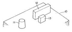
図1〜図4は第1実施の形態の構造を示している。図3に示すように、バッテリ本体10の上面蓋部には正極(+)用と負極(−)用の電力取出し端子である電極ポスト11が垂直に立ち上って設けられている。また、その電極ポスト11の近傍には、次に説明する端子金具20の姿勢が作業時に位置ぶれや位置ずれを生じたり、がたつきなどで不安定となって作業に支障を与えるのを防ぐため、本発明でいう位置決め部の当て板12,13が固設されている。
【0021】
図4は、正負両極の各電極ポスト11にそれぞれ対応して接続されるケーブル15の末端に固着した端子金具20を斜め下方からみた図である。ケーブル15の端部は絶縁体を剥離して導体16を露出させており、この導体16に端子金具20の金具本体21の基端側に設けたかしめ部22がかしめなどして固着されている。また、金具本体21の先端部には鉢巻き形状に成形された円環形のポスト巻き付け部23が設けられ、円環状にほぼ一周して鉢巻き状に交差したその先端部が連結腕部24として形成され、ピン孔24aが設けてある。
【0022】
図1(a),(b)および図2に示すように、かかる端子金具20側の連結腕部24の先端部にロックレバー30が支軸ピン25を介して回動可能に軸支されている。
【0023】
ロックレバー30は、たとえば金型によって樹脂成形されたもので、図示のように、レバー本体側壁部31とこれに直角なレバー本体天板部32を主要部とした細長いキャップ形状である。そうしたキャップ形状の基端側に肉厚のロックカム部34が外側のブラケット部35との間に端子金具20側の連結腕部24を挟み込む板厚一枚分の隙間をあけて一体成形されている。ブラケット部35にはピン孔35aが設けられ、このピン孔35aの同軸上でロックカム部34にも同様なピン孔が設けられている。
【0024】
このロックカム部34およびブラケット部35間に上記端子金具20側の連結腕部24が支軸ピン25によって相対に回動可能に連結されている。そうした肉厚成形部のロックカム部34においては、支軸ピン25の軸心から偏心した距離にカム面34aが形成され、このカム面34aは端子金具20側のポスト巻き付け部23の根元部、つまり金具本体21の先端部に外側面から当接状態となっている。
【0025】
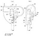
また、キャップ形状のロックレバー30の先端部は、レバー本体側壁部31とレバー本体天板部32とが直交したアングル形の押圧操作端33となっている。接続ロック前の平面図である図1(a)において、押圧操作端33と上記支軸ピン25とを結ぶ距離を回転半径として、図中の矢印Pで示す回動力をその押圧操作端33に加えるようになっている。その回動力Pによって支軸ピン25を回動支点にしてロックレバー30全体が図でいう反時計廻り方向のロック方向に向かって回動可能である。
【0026】
次に、以上の構成による本実施の形態のケーブル端子接続構造について、図1(a),(b)を中心に各図を参照して、バッテリ本体10上の電極ポスト11にケーブル15を電気的に接続する際の組立態様および作用を説明する。
【0027】
まず、バッテリ本体10上の電極ポスト11にその極性に対応するケーブル15を接続するにあたって、あらかじめそのケーブル15の端部の絶縁体を剥離して導体16を露出させ、この導体16に端子金具20のかしめ部22をかしめなどの方法で固着して結合したものが準備される。
【0028】
図1(a)に示すように、そのように準備したケーブル15を電極ポスト11に臨ませ、端子金具20の金具本体21をバッテリ本体10上の当て板12,13間に挟み込むようにして位置決めする。それにより、金具本体21の姿勢が安定してぶれることなく、次段階の本締めつまりロック作業に能率的に移行することができる。その際、同時にその金具本体21の先端のポスト巻き付け部23を電極ポスト11に上から落とし込んで巻き付かせて仮決め状態にセットする。
【0029】
そのようにして端子金具20を電極ポスト11に対して仮決めしたセット状態から、ロックレバー30の押圧操作端33に回動力Pを加えて、ロックレバー30を支軸ピン25を回転中心にして反時計廻りの方向へ回動させる。同方向へロックカム部34が回動することにより、回転モーメントによってカム面34aが変位して支軸ピン25からの偏心距離に相応した梃子力で相手の当接面である端子金具20の金具本体21に外側から押圧力として働く。
【0030】
金具本体21にカム面34aからの押圧力が働くと、金具本体21が内側に曲げられて弾性変形し、それに応じて鉢巻き形状のポスト巻き付け部23がその径を縮小する方向へ絞られて弾性変形する。
【0031】
図1(b)は、そうした弾性変形によってロックレバー30が支軸ピン25を中心にほぼ90゜の角度範囲を回動したロック位置に達した段階で、ロックカム部34のカム面34aによる端子金具20側への押圧が終了した状態を示している。その際、端子金具20のポスト巻き付け部23は鉢巻き形状を縮小変形して電極ポスト11を堅く締め付け、端子金具20がロック状態に結合されてケーブル15の電極ポスト11への電気的な接続作業を終了する。
【0032】
ここまでの動作および作用からわかるように、端子金具20をバッテリ本体10上の電極ポスト11および当て板12,13にそれぞれ係合させた仮決め状態から、ロックレバー30をほぼ90゜の角度だけ回動操作してロック状態に終了するまでの一連の作業が、作業者は両手を用いることなくいずれかの片手操作で済む。すなわち、従来例の図7(a),(b)で示したように、レバー回転操作に追従して金具本体側が共回りするために、一方の手で金具本体側ケーブルを把持して支持し、もう片方の手でレバー操作するといった作業勝手上の不便性を解消し、作業を能率アップできる。
【0033】
一方、図5(a),(b)および図6は、上記第1実施の形態の改良案ともいうべき本発明にかかる第2実施の形態の構造を示している。
【0034】
この場合、第1の実施の形態で示されたロックレバー30に設けたロックカム部34において、カム面34aに代えてカム凸部34bを山形に突出させて設けた構造である。他の細部構造については第1実施の形態と同様であり、対応する部材や部分に同一符号を付してある。
【0035】
したがって、ロックカム部34にカム凸部34bを設けたことにより、図5(b)に示すロック本締め状態のように、カム凸部34bによって端子金具20のポスト巻き付け部23に梃子力が集中力となって働き、ポスト巻き付け部23を変形させて電極ポスト11を締め付けるのに一層有効である。
【0036】
【発明の効果】
以上説明したように、本発明にかかる請求項1に記載のバッテリのケーブル端子接続構造は、ケーブル端部に固着した端子金具をバッテリ本体上の電極ポストと位置決め部に位置決めして仮決め状態にセットしてから、ロックレバーによる回動操作でその端子金具が電極ポストに堅く締め付けられてロック状態になる。すなわち、仮決め状態からロック状態にするまでの作業において、端子金具は常に安定姿勢に維持されるので、ロックレバーの操作で端子金具が共回りするといった作業上の不具合が解消され、作業者は片手操作で作業を行える。
【0037】
また、請求項2に記載のバッテリのケーブル端子接続構造は、ロックレバーを樹脂成形することによって、仮決め状態からロック状態へのほぼ90゜の角度回動中に適度な弾性変形が得られ、ロックカム部の押圧による端子金具側の変形と連動することにより、樹脂特有の変形でもって端子金具を電極ポストに堅く締め付けることが可能となる。
【0038】
また、請求項3に記載のバッテリのケーブル端子接続構造は、上記請求項2に関連して、ロックレバーを樹脂成形することにより、ロック状態に達した段階でケーブル端部と端子金具との固着部領域を覆って保護できる形状に成形することができる。
【0039】
また、請求項4に記載のバッテリのケーブル端子接続構造は、ロックレバーを梃子とした場合に、このロックレバーの基端に設けたロックカム部と端子金具側の連結腕部との連結部である支軸ピンが梃子支点になり、併せてバッテリ本体上の位置決め部によって金具本体を位置決め保持する部分も梃子支点となる。その場合に、ロックカム部のカム面またはカム凸部で押圧される端子金具側の鉢巻き形状のポスト巻き付け部が電極ポストを締め付ける部分が梃子力点となる。そうしたロックレバーによる回転モーメントを梃子力に変換することで、ロックレバーに対して作業者の片手操作だけで能率的にほぼワンタッチでケーブルを電極ポストにロック状態で電気的に接続することができる。
【図面の簡単な説明】
【図1】同図(a),(b)は、本発明にかかる第1実施の形態の構造において接続ロック前と接続ロック後の状態を示すそれぞれの平面図である。
【図2】電極ポストに対して第1実施の形態による端子金具とロックレバーとの取り合いを斜め下方からみて示す斜視図である。
【図3】バッテリ本体上においてこの第1実施の形態を構成する電極ポストと当て板を示す斜視図である。
【図4】第1実施の形態における端子金具の単体を斜め下方からみて示す斜視図である。
【図5】同図(a),(b)は、本発明にかかる第2実施の形態の構造において接続ロック前と接続ロック後の状態を示すそれぞれの平面図である。
【図6】電極ポストに対して第2実施の形態による端子金具とロックレバーとの取り合いを斜め下方からみて示す斜視図である。
【図7】同図(a),(b)は、従来例の構造において接続ロック前と接続ロック後の状態を示すそれぞれの平面図である。
【符号の説明】
10 バッテリ本体
11 正負極の電極ポスト
12,13 当て板(位置決め部)
15 ケーブル
16 導体
20 端子金具
21 金具本体
22 かしめ部
23 ポスト巻き付け部
24 連結腕部
25 支軸ピン
30 ロックレバー
31 レバー本体側壁部
32 レバー本体天板部
34 ロックカム部
33 押圧操作端
34a カム面
34b カム凸部
35 ブラケット部
35a ピン孔[0001]
BACKGROUND OF THE INVENTION
The present invention relates to a cable terminal connection structure for connecting a wire / cable terminal to positive and negative electrode posts, particularly in a power supply battery mounted on an automobile.
[0002]
[Prior art]
Conventionally, there is a battery terminal described in Japanese Utility Model Publication No. 6-5109 as a conventional example of this type of cable terminal connection structure. This is schematically shown in FIGS. 7 (a) and 7 (b) in plan view.
[0003]
Both positive and negative electrode posts 1 are set up on the battery body, and cables 2 corresponding to the positive and negative electrode posts 1 are connected via
[0004]
The
[0005]
The
[0006]
Accordingly, as shown in FIG. 5A, from the temporarily determined state in which the post winding
[0007]
[Problems to be solved by the invention]
Incidentally, the conventional structure shown in FIGS. 7A and 7B has the following problems.
[0008]
When the
[0009]
Accordingly, an object of the present invention is to provide an unstable posture when the terminal fitting itself in the temporarily determined state rotates together with the operation force for locking to the electrode post during the operation of connecting the cable to the electrode post via the terminal fitting. It is an object of the present invention to provide a battery cable terminal connection structure that prevents the occurrence of the problem and increases the efficiency of connection work.
[0010]
[Means for Solving the Problems]
In order to achieve the above object, the battery cable terminal connection structure according to claim 1 according to the present invention includes a
[0011]
With the above configuration, the terminal fitting 20 fixed to the end of the
[0012]
Further, in the battery cable terminal connection structure according to claim 2, the
[0013]
With the above configuration, in this case, by molding the
[0014]
In the battery cable terminal connection structure according to
[0015]
In this case, in relation to the above-mentioned claim 2, by forming the
[0016]
According to a fourth aspect of the present invention, the battery cable terminal connection structure according to the fourth aspect of the present invention has a lever operating point on the battery main body 10 to which an operation force is applied. Both the portion where the metal
[0017]
That is, when the
[0018]
In this case, if the
[0019]
DETAILED DESCRIPTION OF THE INVENTION
Embodiments of a battery cable terminal connection structure according to the present invention will be described below in detail with reference to the drawings.
[0020]
1 to 4 show the structure of the first embodiment. As shown in FIG. 3, an electrode post 11, which is a power extraction terminal for a positive electrode (+) and a negative electrode (−), is provided on the upper surface lid of the battery body 10 so as to stand vertically. Further, in the vicinity of the electrode post 11, the posture of the terminal fitting 20 to be described next is prevented from being displaced or displaced at the time of work, or unstable due to rattling or the like, and hindering work. Therefore, the
[0021]
FIG. 4 is a view of the terminal fitting 20 fixed to the end of the
[0022]
As shown in FIGS. 1A, 1B, and 2, a
[0023]
The
[0024]
A connecting
[0025]
Further, the tip of the cap-shaped
[0026]
Next, regarding the cable terminal connection structure of the present embodiment having the above configuration, the
[0027]
First, when connecting the
[0028]
As shown in FIG. 1 (a), the
[0029]
Thus, from the set state in which the terminal fitting 20 is tentatively determined with respect to the electrode post 11, the rotational force P is applied to the
[0030]
When a pressing force from the
[0031]
FIG. 1B shows a terminal fitting formed by the
[0032]
As can be seen from the operations and actions so far, the
[0033]
On the other hand, FIGS. 5A, 5B and 6 show the structure of the second embodiment according to the present invention, which should be referred to as an improvement plan of the first embodiment.
[0034]
In this case, the
[0035]
Therefore, by providing the cam
[0036]
【The invention's effect】
As described above, in the battery cable terminal connection structure according to claim 1 of the present invention, the terminal fitting fixed to the cable end portion is positioned on the electrode post and the positioning portion on the battery body to be in a temporarily determined state. After the setting, the terminal fitting is firmly tightened to the electrode post by the turning operation by the lock lever to be in the locked state. That is, in the work from the temporarily determined state to the locked state, the terminal metal fitting is always maintained in a stable posture, so that the work trouble such as the terminal metal fitting rotating together by the operation of the lock lever is solved, and the operator Work with one hand.
[0037]
Further, in the battery cable terminal connection structure according to claim 2, by elastically molding the lock lever, an appropriate elastic deformation can be obtained during an angle rotation of approximately 90 ° from the temporarily determined state to the locked state. By interlocking with the deformation on the side of the terminal fitting due to the pressing of the lock cam portion, the terminal fitting can be firmly tightened to the electrode post with the deformation unique to the resin.
[0038]
According to a third aspect of the present invention, there is provided the battery cable terminal connection structure according to the second aspect, wherein the cable end and the terminal fitting are fixed when the lock lever is reached by resin molding the lock lever. It can be formed into a shape that covers and protects the partial area.
[0039]
The battery cable terminal connection structure according to
[Brief description of the drawings]
FIGS. 1A and 1B are plan views showing states before and after connection locking in the structure according to the first embodiment of the present invention, respectively.
FIG. 2 is a perspective view showing an engagement between the terminal fitting and the lock lever according to the first embodiment with respect to the electrode post as viewed obliquely from below.
FIG. 3 is a perspective view showing an electrode post and a contact plate constituting the first embodiment on the battery body.
FIG. 4 is a perspective view showing a single terminal fitting according to the first embodiment as viewed obliquely from below.
FIGS. 5A and 5B are plan views showing states before and after connection locking in the structure of the second embodiment according to the present invention, respectively.
FIG. 6 is a perspective view showing an engagement between the terminal fitting and the lock lever according to the second embodiment with respect to the electrode post as viewed obliquely from below.
FIGS. 7A and 7B are plan views showing states before and after connection locking in the structure of the conventional example, respectively.
[Explanation of symbols]
DESCRIPTION OF SYMBOLS 10 Battery main body 11 Positive and
15
Claims (4)
Translated fromJapanese前記端子金具は、金具本体の先端に前記電極ポストを外側から鉢巻き状に巻き付ける円環形のポスト巻き付け部を有し、さらにそのポスト巻き付け部の鉢巻き部分の先端から延びた連結腕部を有してなっており、一方、
前記バッテリ本体の電極ポストの近傍には前記端子金具側の金具本体を挟み込んで位置決めするための位置決め部が設けられ、また、
前記端子金具側の連結腕部に支軸ピンを介して回動可能に連結された前記ロックレバーのレバー長手方向の基端に設けたロックカム部には回動中心の前記支軸ピンから偏心した距離にカム面またはカム凸部が形成されており、
前記ロックレバーの回動モーメントで前記カム面またはカム凸部を前記金具本体に押し当てることによって該金具本体を内側に曲げて変形させ、そして前記鉢巻き状のポスト巻き付け部を締め込み方向に変形させ、前記端子金具を前記電極ポストにロック状態で接続してなることを特徴とするバッテリのケーブル端子接続構造。A battery cable terminal connection structure in which a cable corresponding to the polarity is connected to each of the positive and negative electrode posts provided on the battery body via a terminal fitting at the end,and is used when connecting to the electrode posts. In the battery cable terminal connection structure provided with a lock lever on the terminal fitting,
The terminal fitting has a ring-shaped post winding portion for winding the electrode post in a bowl shape from the outside at the tip of the fitting main body, and further has a connecting arm portion extending from the tip of the bowl winding portion of the post winding portion. On the other hand,
In the vicinity of the electrode post of the battery body, a positioning part is provided for sandwiching and positioning the metal fitting body on the terminal metal fitting side,
Offset from the pivot pin of the pivot centerin the lock cam lever provided in the longitudinal direction of the base endof the metal terminal sidethe lock lever which is pivotally connected via a pivot pin to the connecting arm portion of the Cam surface or cam projection is formed at the distance,
Bybending the cam surface or cam convex portion against the metal fitting body by the rotation moment of the lock lever, the metal fitting bodyis bent and deformed inward, and the headband-shaped post winding portion is deformed in the tightening direction. The battery terminal connection structure for a battery, wherein the terminal fitting is connected to the electrode post in a locked state.
Priority Applications (4)
| Application Number | Priority Date | Filing Date | Title |
|---|---|---|---|
| JP2000173328AJP3654819B2 (en) | 2000-06-09 | 2000-06-09 | Battery cable terminal connection structure |
| EP01304945AEP1162693B1 (en) | 2000-06-09 | 2001-06-06 | Cable terminal connecting structure of battery |
| DE60124177TDE60124177T2 (en) | 2000-06-09 | 2001-06-06 | Battery cable clamp connection structure |
| US09/877,076US6524141B2 (en) | 2000-06-09 | 2001-06-11 | Cable terminal connecting structure of battery |
Applications Claiming Priority (1)
| Application Number | Priority Date | Filing Date | Title |
|---|---|---|---|
| JP2000173328AJP3654819B2 (en) | 2000-06-09 | 2000-06-09 | Battery cable terminal connection structure |
Publications (2)
| Publication Number | Publication Date |
|---|---|
| JP2001351607A JP2001351607A (en) | 2001-12-21 |
| JP3654819B2true JP3654819B2 (en) | 2005-06-02 |
Family
ID=18675584
Family Applications (1)
| Application Number | Title | Priority Date | Filing Date |
|---|---|---|---|
| JP2000173328AExpired - Fee RelatedJP3654819B2 (en) | 2000-06-09 | 2000-06-09 | Battery cable terminal connection structure |
Country Status (4)
| Country | Link |
|---|---|
| US (1) | US6524141B2 (en) |
| EP (1) | EP1162693B1 (en) |
| JP (1) | JP3654819B2 (en) |
| DE (1) | DE60124177T2 (en) |
Cited By (1)
| Publication number | Priority date | Publication date | Assignee | Title |
|---|---|---|---|---|
| US11456609B1 (en)* | 2022-02-04 | 2022-09-27 | Lat Enterprises, Inc. | Battery harvesting adapter |
Families Citing this family (14)
| Publication number | Priority date | Publication date | Assignee | Title |
|---|---|---|---|---|
| JP3679357B2 (en)* | 2001-10-02 | 2005-08-03 | 矢崎総業株式会社 | Battery connector |
| US7303448B1 (en)* | 2006-05-24 | 2007-12-04 | East Penn Manufacturing Co., Inc. | Battery terminal connector with reversible clamp lever |
| FR2904482B1 (en)* | 2006-07-28 | 2008-10-10 | Tyco Electronics France Sas | CONNECTOR FOR BATTERY TERMINAL |
| US7690953B2 (en)* | 2007-05-03 | 2010-04-06 | Deringer-Ney, Inc. | Stackable electrical connection apparatus |
| US7374464B1 (en)* | 2007-07-06 | 2008-05-20 | Tyco Electronics Brasil Ltda. | Quick connection battery terminal |
| US8038484B2 (en) | 2007-12-11 | 2011-10-18 | Tyco Healthcare Group Lp | ECG electrode connector |
| US8426773B2 (en)* | 2008-02-27 | 2013-04-23 | Illinois Tool Works Inc. | Dual power pin connector assembly for a MIG welding machine |
| US7749030B1 (en)* | 2008-07-21 | 2010-07-06 | Smith Michael W | Battery terminal-cable connector |
| USD737979S1 (en) | 2008-12-09 | 2015-09-01 | Covidien Lp | ECG electrode connector |
| ES2762190T3 (en) | 2011-07-22 | 2020-05-22 | Kpr Us Llc | ECG electrode connector |
| CN102368576A (en)* | 2011-09-09 | 2012-03-07 | 章丘市太和电器有限公司 | Rapid storage battery joint |
| USD771818S1 (en) | 2013-03-15 | 2016-11-15 | Covidien Lp | ECG electrode connector |
| US9408546B2 (en)* | 2013-03-15 | 2016-08-09 | Covidien Lp | Radiolucent ECG electrode system |
| CN105120742B (en) | 2013-03-15 | 2017-07-28 | 柯惠有限合伙公司 | Electrode connector with conductive component |
Family Cites Families (11)
| Publication number | Priority date | Publication date | Assignee | Title |
|---|---|---|---|---|
| US1808775A (en)* | 1929-08-12 | 1931-06-09 | Hofman Tenis | Clamp for battery terminal posts |
| US4125683A (en)* | 1977-11-09 | 1978-11-14 | Globe-Union Inc. | Adjustable battery stacking spacer |
| US4555159A (en)* | 1984-08-06 | 1985-11-26 | Chartrain Armand N | Battery post connector |
| ES8609823A1 (en)* | 1985-07-22 | 1986-09-01 | Tudor Acumulador | Electric accumulator battery. |
| JPH07506695A (en)* | 1992-05-12 | 1995-07-20 | マトソン オートモーティブ インダストリーズ ピーティーワイ リミテッド | battery terminal connector |
| JP2574239Y2 (en)* | 1992-06-23 | 1998-06-11 | 住友電装株式会社 | Battery terminal |
| JPH065109A (en) | 1992-06-23 | 1994-01-14 | Matsushita Electric Works Ltd | Solar lighting device |
| US5389462A (en)* | 1993-11-17 | 1995-02-14 | Ztong Yee Industrial Co., Ltd. | Storage battery |
| US5575693A (en)* | 1995-10-11 | 1996-11-19 | The United States Of America As Represented By The Secretary Of The Army | Battery post connector |
| ES1038047Y (en)* | 1997-08-06 | 1998-11-01 | Mecanismos Aux Ind | PERFECTED BATTERY TERMINAL. |
| ES1040585Y (en)* | 1998-07-01 | 1999-08-16 | Mecanismos Aux Ind | FIXING BATTERY TERMINAL WITH CAM. |
- 2000
- 2000-06-09JPJP2000173328Apatent/JP3654819B2/ennot_activeExpired - Fee Related
- 2001
- 2001-06-06EPEP01304945Apatent/EP1162693B1/ennot_activeExpired - Lifetime
- 2001-06-06DEDE60124177Tpatent/DE60124177T2/ennot_activeExpired - Fee Related
- 2001-06-11USUS09/877,076patent/US6524141B2/ennot_activeExpired - Fee Related
Cited By (3)
| Publication number | Priority date | Publication date | Assignee | Title |
|---|---|---|---|---|
| US11456609B1 (en)* | 2022-02-04 | 2022-09-27 | Lat Enterprises, Inc. | Battery harvesting adapter |
| US11715966B1 (en) | 2022-02-04 | 2023-08-01 | Lat Enterprises, Inc. | Battery harvesting adapter |
| US12119693B1 (en) | 2022-02-04 | 2024-10-15 | Lat Enterprises, Inc. | Battery harvesting adapter |
Also Published As
| Publication number | Publication date |
|---|---|
| EP1162693B1 (en) | 2006-11-02 |
| US6524141B2 (en) | 2003-02-25 |
| EP1162693A2 (en) | 2001-12-12 |
| JP2001351607A (en) | 2001-12-21 |
| EP1162693A3 (en) | 2002-10-02 |
| US20010053639A1 (en) | 2001-12-20 |
| DE60124177D1 (en) | 2006-12-14 |
| DE60124177T2 (en) | 2007-09-06 |
Similar Documents
| Publication | Publication Date | Title |
|---|---|---|
| JP3654819B2 (en) | Battery cable terminal connection structure | |
| JP3753410B2 (en) | Battery cable terminal connection structure | |
| JP2538866Y2 (en) | Rotating connector | |
| JPH07335193A (en) | Battery terminal | |
| JP5594896B2 (en) | Quick connect battery terminals | |
| JP3064793B2 (en) | Terminal fitting | |
| JP3645474B2 (en) | Battery terminal connection structure | |
| JP3473515B2 (en) | Mounting structure of round plate terminals | |
| JP2001256956A (en) | Battery terminal connector | |
| JPH11274825A (en) | Antenna fixing device | |
| JPH11273657A (en) | Battery terminal | |
| JP2004355908A (en) | Battery terminal | |
| JP2020205231A (en) | connector | |
| JP3433441B2 (en) | Battery terminal | |
| JPH0629894Y2 (en) | Bobbin type lithium battery | |
| JPH0531129U (en) | Starter | |
| JP2008243458A (en) | Battery terminal | |
| JP2024135052A (en) | Connector device | |
| WO2020250740A1 (en) | Connector | |
| JP2003109578A (en) | Battery terminal | |
| JPH0236171Y2 (en) | ||
| JPH0313979Y2 (en) | ||
| JPH055674Y2 (en) | ||
| JPH09147934A (en) | Earth terminal mounting structure | |
| JP2522940Y2 (en) | Stepping motor |
Legal Events
| Date | Code | Title | Description |
|---|---|---|---|
| A977 | Report on retrieval | Free format text:JAPANESE INTERMEDIATE CODE: A971007 Effective date:20041101 | |
| A131 | Notification of reasons for refusal | Free format text:JAPANESE INTERMEDIATE CODE: A131 Effective date:20041124 | |
| A521 | Request for written amendment filed | Free format text:JAPANESE INTERMEDIATE CODE: A523 Effective date:20050124 | |
| TRDD | Decision of grant or rejection written | ||
| A01 | Written decision to grant a patent or to grant a registration (utility model) | Free format text:JAPANESE INTERMEDIATE CODE: A01 Effective date:20050222 | |
| A61 | First payment of annual fees (during grant procedure) | Free format text:JAPANESE INTERMEDIATE CODE: A61 Effective date:20050301 | |
| R150 | Certificate of patent or registration of utility model | Free format text:JAPANESE INTERMEDIATE CODE: R150 | |
| LAPS | Cancellation because of no payment of annual fees |