JP3653923B2 - Recording / reproducing apparatus and method - Google Patents
Recording / reproducing apparatus and methodDownload PDFInfo
- Publication number
- JP3653923B2 JP3653923B2JP06585097AJP6585097AJP3653923B2JP 3653923 B2JP3653923 B2JP 3653923B2JP 06585097 AJP06585097 AJP 06585097AJP 6585097 AJP6585097 AJP 6585097AJP 3653923 B2JP3653923 B2JP 3653923B2
- Authority
- JP
- Japan
- Prior art keywords
- light
- wavelength
- hoe
- laser
- incident
- Prior art date
- Legal status (The legal status is an assumption and is not a legal conclusion. Google has not performed a legal analysis and makes no representation as to the accuracy of the status listed.)
- Expired - Lifetime
Links
- 238000000034methodMethods0.000titledescription23
- 230000003287optical effectEffects0.000claimsdescription160
- 230000004075alterationEffects0.000claimsdescription36
- 239000000758substrateSubstances0.000claimsdescription25
- 206010073261Ovarian theca cell tumourDiseases0.000claimsdescription4
- 208000001644thecomaDiseases0.000claimsdescription4
- 230000001678irradiating effectEffects0.000claimsdescription3
- 238000010586diagramMethods0.000description31
- 238000001514detection methodMethods0.000description13
- 239000002131composite materialSubstances0.000description11
- 201000009310astigmatismDiseases0.000description8
- 230000005855radiationEffects0.000description7
- 206010010071ComaDiseases0.000description6
- 230000010287polarizationEffects0.000description5
- 230000002238attenuated effectEffects0.000description3
- 210000001747pupilAnatomy0.000description3
- 238000003384imaging methodMethods0.000description2
- 230000002411adverseEffects0.000description1
- 230000015572biosynthetic processEffects0.000description1
- 230000000694effectsEffects0.000description1
- 238000005530etchingMethods0.000description1
- 230000000873masking effectEffects0.000description1
- 238000005549size reductionMethods0.000description1
- 238000003786synthesis reactionMethods0.000description1
- 230000002194synthesizing effectEffects0.000description1
Images


Classifications
- G—PHYSICS
- G11—INFORMATION STORAGE
- G11B—INFORMATION STORAGE BASED ON RELATIVE MOVEMENT BETWEEN RECORD CARRIER AND TRANSDUCER
- G11B7/00—Recording or reproducing by optical means, e.g. recording using a thermal beam of optical radiation by modifying optical properties or the physical structure, reproducing using an optical beam at lower power by sensing optical properties; Record carriers therefor
- G11B7/004—Recording, reproducing or erasing methods; Read, write or erase circuits therefor
- G—PHYSICS
- G11—INFORMATION STORAGE
- G11B—INFORMATION STORAGE BASED ON RELATIVE MOVEMENT BETWEEN RECORD CARRIER AND TRANSDUCER
- G11B7/00—Recording or reproducing by optical means, e.g. recording using a thermal beam of optical radiation by modifying optical properties or the physical structure, reproducing using an optical beam at lower power by sensing optical properties; Record carriers therefor
- G11B7/12—Heads, e.g. forming of the optical beam spot or modulation of the optical beam
- G11B7/135—Means for guiding the beam from the source to the record carrier or from the record carrier to the detector
- G11B7/1372—Lenses
- G—PHYSICS
- G11—INFORMATION STORAGE
- G11B—INFORMATION STORAGE BASED ON RELATIVE MOVEMENT BETWEEN RECORD CARRIER AND TRANSDUCER
- G11B7/00—Recording or reproducing by optical means, e.g. recording using a thermal beam of optical radiation by modifying optical properties or the physical structure, reproducing using an optical beam at lower power by sensing optical properties; Record carriers therefor
- G11B7/12—Heads, e.g. forming of the optical beam spot or modulation of the optical beam
- G11B7/123—Integrated head arrangements, e.g. with source and detectors mounted on the same substrate
- G—PHYSICS
- G11—INFORMATION STORAGE
- G11B—INFORMATION STORAGE BASED ON RELATIVE MOVEMENT BETWEEN RECORD CARRIER AND TRANSDUCER
- G11B7/00—Recording or reproducing by optical means, e.g. recording using a thermal beam of optical radiation by modifying optical properties or the physical structure, reproducing using an optical beam at lower power by sensing optical properties; Record carriers therefor
- G11B7/12—Heads, e.g. forming of the optical beam spot or modulation of the optical beam
- G11B7/125—Optical beam sources therefor, e.g. laser control circuitry specially adapted for optical storage devices; Modulators, e.g. means for controlling the size or intensity of optical spots or optical traces
- G11B7/127—Lasers; Multiple laser arrays
- G11B7/1275—Two or more lasers having different wavelengths
- G—PHYSICS
- G11—INFORMATION STORAGE
- G11B—INFORMATION STORAGE BASED ON RELATIVE MOVEMENT BETWEEN RECORD CARRIER AND TRANSDUCER
- G11B7/00—Recording or reproducing by optical means, e.g. recording using a thermal beam of optical radiation by modifying optical properties or the physical structure, reproducing using an optical beam at lower power by sensing optical properties; Record carriers therefor
- G11B7/12—Heads, e.g. forming of the optical beam spot or modulation of the optical beam
- G11B7/13—Optical detectors therefor
- G11B7/131—Arrangement of detectors in a multiple array
- G—PHYSICS
- G11—INFORMATION STORAGE
- G11B—INFORMATION STORAGE BASED ON RELATIVE MOVEMENT BETWEEN RECORD CARRIER AND TRANSDUCER
- G11B7/00—Recording or reproducing by optical means, e.g. recording using a thermal beam of optical radiation by modifying optical properties or the physical structure, reproducing using an optical beam at lower power by sensing optical properties; Record carriers therefor
- G11B7/12—Heads, e.g. forming of the optical beam spot or modulation of the optical beam
- G11B7/135—Means for guiding the beam from the source to the record carrier or from the record carrier to the detector
- G11B7/1353—Diffractive elements, e.g. holograms or gratings
- G—PHYSICS
- G11—INFORMATION STORAGE
- G11B—INFORMATION STORAGE BASED ON RELATIVE MOVEMENT BETWEEN RECORD CARRIER AND TRANSDUCER
- G11B7/00—Recording or reproducing by optical means, e.g. recording using a thermal beam of optical radiation by modifying optical properties or the physical structure, reproducing using an optical beam at lower power by sensing optical properties; Record carriers therefor
- G11B7/12—Heads, e.g. forming of the optical beam spot or modulation of the optical beam
- G11B7/135—Means for guiding the beam from the source to the record carrier or from the record carrier to the detector
- G11B7/1372—Lenses
- G11B7/1374—Objective lenses
- G—PHYSICS
- G11—INFORMATION STORAGE
- G11B—INFORMATION STORAGE BASED ON RELATIVE MOVEMENT BETWEEN RECORD CARRIER AND TRANSDUCER
- G11B7/00—Recording or reproducing by optical means, e.g. recording using a thermal beam of optical radiation by modifying optical properties or the physical structure, reproducing using an optical beam at lower power by sensing optical properties; Record carriers therefor
- G11B7/24—Record carriers characterised by shape, structure or physical properties, or by the selection of the material
- G11B7/2403—Layers; Shape, structure or physical properties thereof
- G11B7/24047—Substrates
- G—PHYSICS
- G03—PHOTOGRAPHY; CINEMATOGRAPHY; ANALOGOUS TECHNIQUES USING WAVES OTHER THAN OPTICAL WAVES; ELECTROGRAPHY; HOLOGRAPHY
- G03H—HOLOGRAPHIC PROCESSES OR APPARATUS
- G03H2223/00—Optical components
- G03H2223/18—Prism
- G—PHYSICS
- G03—PHOTOGRAPHY; CINEMATOGRAPHY; ANALOGOUS TECHNIQUES USING WAVES OTHER THAN OPTICAL WAVES; ELECTROGRAPHY; HOLOGRAPHY
- G03H—HOLOGRAPHIC PROCESSES OR APPARATUS
- G03H2240/00—Hologram nature or properties
- G03H2240/50—Parameters or numerical values associated with holography, e.g. peel strength
- G03H2240/53—Diffraction efficiency [DE]
- G—PHYSICS
- G03—PHOTOGRAPHY; CINEMATOGRAPHY; ANALOGOUS TECHNIQUES USING WAVES OTHER THAN OPTICAL WAVES; ELECTROGRAPHY; HOLOGRAPHY
- G03H—HOLOGRAPHIC PROCESSES OR APPARATUS
- G03H2240/00—Hologram nature or properties
- G03H2240/50—Parameters or numerical values associated with holography, e.g. peel strength
- G03H2240/54—Refractive index
- G—PHYSICS
- G11—INFORMATION STORAGE
- G11B—INFORMATION STORAGE BASED ON RELATIVE MOVEMENT BETWEEN RECORD CARRIER AND TRANSDUCER
- G11B7/00—Recording or reproducing by optical means, e.g. recording using a thermal beam of optical radiation by modifying optical properties or the physical structure, reproducing using an optical beam at lower power by sensing optical properties; Record carriers therefor
- G11B2007/0003—Recording, reproducing or erasing systems characterised by the structure or type of the carrier
- G11B2007/0006—Recording, reproducing or erasing systems characterised by the structure or type of the carrier adapted for scanning different types of carrier, e.g. CD & DVD
- G—PHYSICS
- G11—INFORMATION STORAGE
- G11B—INFORMATION STORAGE BASED ON RELATIVE MOVEMENT BETWEEN RECORD CARRIER AND TRANSDUCER
- G11B7/00—Recording or reproducing by optical means, e.g. recording using a thermal beam of optical radiation by modifying optical properties or the physical structure, reproducing using an optical beam at lower power by sensing optical properties; Record carriers therefor
- G11B7/12—Heads, e.g. forming of the optical beam spot or modulation of the optical beam
- G11B7/135—Means for guiding the beam from the source to the record carrier or from the record carrier to the detector
- G11B7/1372—Lenses
- G11B2007/13727—Compound lenses, i.e. two or more lenses co-operating to perform a function, e.g. compound objective lens including a solid immersion lens, positive and negative lenses either bonded together or with adjustable spacing
- G—PHYSICS
- G11—INFORMATION STORAGE
- G11B—INFORMATION STORAGE BASED ON RELATIVE MOVEMENT BETWEEN RECORD CARRIER AND TRANSDUCER
- G11B2220/00—Record carriers by type
- G11B2220/20—Disc-shaped record carriers
- G11B2220/25—Disc-shaped record carriers characterised in that the disc is based on a specific recording technology
- G11B2220/2537—Optical discs
- G11B2220/2545—CDs
- G—PHYSICS
- G11—INFORMATION STORAGE
- G11B—INFORMATION STORAGE BASED ON RELATIVE MOVEMENT BETWEEN RECORD CARRIER AND TRANSDUCER
- G11B2220/00—Record carriers by type
- G11B2220/20—Disc-shaped record carriers
- G11B2220/25—Disc-shaped record carriers characterised in that the disc is based on a specific recording technology
- G11B2220/2537—Optical discs
- G11B2220/2562—DVDs [digital versatile discs]; Digital video discs; MMCDs; HDCDs
Landscapes
- Physics & Mathematics (AREA)
- Optics & Photonics (AREA)
- Optical Head (AREA)
Description
Translated fromJapanese【0001】
【発明の属する技術分野】
本発明は、記録再生装置に関し、特に、第1の波長の光と、第2の波長の光を用いて、それぞれ異なる記録媒体に対して、情報を記録または再生する場合に、より小型化できるようにした記録再生装置に関する。
【0002】
【従来の技術】
光を利用して情報を記録または再生する記録媒体として、コンパクトディスク(CD)(商標)、CD−ROM、CD−Rなどの光ディスクが普及しているが、最近では、その他に、大容量のデータを記録するDVD(Digital Versatile Disc)などの新たな記録媒体が開発されつつある。
【0003】
このような光ディスクからデジタル情報を読み出す場合、レーザ光を記録媒体に集光し、記録媒体からの反射光を検出し、反射光のレベルを2値データに変換する。
【0004】
高密度の光ディスクにおいては、短波長のレーザ光を利用し(例えば、CDを再生する場合、波長λはλ=780nmとされ、より高密度にデータが記録されているDVDを再生する場合、λ=635乃至650nmとされる)、開口数(NA)の大きい(例えば、CDを再生する場合、NA=0.45とされ、DVDを再生する場合、NA=0.6とされる)対物レンズを使用してレーザ光をより狭い範囲に収束させ、その反射光を受光して、記録されている情報を再生する。
【0005】
そのような開口数(NA)の大きい対物レンズを使用すると、光ディスクの傾き(スキュー)に起因して、反射光における収差量が増大するため、DVDではCDにおける場合より基板を薄く設計し(CDの1.2mmに対し、DVDでは0.6mm)、反射光における収差量を低減している。
【0006】
以上のような、対物レンズのNAとレーザ光の波長λの値に応じて規定される集光スポットのサイズ(λ/NAに比例する)の違い、および、光ディスクの基板の厚さに応じて生じる球面収差の量の違いにより、従来のCDに記録されている情報を読み出す光学系を、そのまま、DVDの再生に利用することは困難であり、その逆に、DVD用に設計した光学系をCDの再生にそのまま利用することも困難である。
【0007】
しかしながら、今後、CDなどの従来の光ディスクと、DVDなどの高密度の光ディスクは共存していくものと考えられるので、それらの光ディスクを再生する場合、光ディスクの種類毎に専用の再生装置を用意しなければならないとすれば不便である。
【0008】
そこで、このような記録密度と基板の厚さが異なる複数の光ディスクを1つの装置で再生する方法がいくつか提案されている。
【0009】
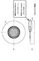
そのうちの1つとして、対物レンズと、ホログラフィック光学素子(HOE)を組み合わせる方法が、例えば、特開平7−98431号公報に開示されている。図29は、同公報に記載の技術の原理を表している。すなわち、同図に示すように、例えば650nmの波長のレーザ光が、HOE101と対物レンズ102を介して、CD103またはDVD104に照射される。HOE101には、図30に示すように、同心円状の鋸歯状または階段状の凹凸よりなる輪帯構造が形成されている。その結果、図31に示すように、入射された650nmの波長の光が0次回折光(透過光)と1次回折光に分割される。0次回折光は、DVD用とされ、1次回折光は、CD用とされる。それ以外の次数の回折光は、実質的に殆ど0となるように、HOE101は最適化されている。
【0010】
対物レンズ102は、DVD104に最適化されている。その結果、HOE101を透過した0次回折光は、図29に示すように、対物レンズ102により、基板の厚さが0.6mmのDVD104の情報記録面上に集束される。また、HOE101の輪帯のピッチは、1次回折光が、対物レンズ102を経て、厚さが約1.2mmの基板を有するCD103に集束されるとき、DVD104との基板厚の違いによる球面収差を補正するように最適化されている。また、この輪帯の径は、CD103に最適なNAが得られるように、対物レンズ102の有効径より小さい領域に形成してある。その結果、対物レンズ102を透過した1次回折光は、情報記録面上に回折限界まで集光され、良好な光スポットが形成される。
【0011】
また、このHOE101の輪帯のピッチは、CD103の光スポットがDVD104の光スポットから光軸方向に数百μm離れるように最適化してあるため、各光スポットが他方の再生RF信号に影響を与えないようになされている。
【0012】
しかしながら、このようなピックアップにおいては、使用されている波長が650nmと短いため、通常のCDは再生できても、CD−Rを再生することができない。すなわち、再生だけでなく書き込みも可能なCD−Rは、780nmの帯域の波長を反射するように形成されており、DVDで用いる650nmの長さの波長は、殆ど吸収してしまうからである。
【0013】
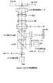
そこで、本出願人は、例えば特願平8−121337号として、CD−Rを含むCDとDVDの両方を再生することが可能なピックアップを提案した。図32と図33は、その構成例を表している。図32は、DVD104を再生する場合の光学系を表しており、図33は、CD103を再生する場合の光学系の状態を表している。
【0014】
DVD104を再生する場合には、図32に示すように、780nmの波長のレーザ光を発生する放射光源111Bはオフされる。そして、650nmの波長のレーザ光を発生する放射光源111Aがオンされる。放射光源111Aより出射されたレーザ光は、グレーティング112Aにより、実質的に3本のレーザ光に分割された後、ダイクロイックプリズム(DP)113と偏光ビームスプリッタ(PBS)114を透過して、コリメータレンズ115に入射される。コリメータレンズ115は、入射された発散光を平行光に変換して、λ/4板116を介して、HOE117に入射させる。屈折型対物レンズ118は、DVD104に最適化されて設計されている。従って、HOE117は、屈折型対物レンズ118により、CD103に集束される780nmの波長の光の球面収差を補正するように最適化されており、650nmの波長の光には、実質的に機能しない。
【0015】
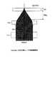
すなわち、図34に拡大して示すように、HOE117は、波長650nmのレーザ光をほぼ100%透過する。すなわち、HOE117からは、0次回折光が出射される。このレーザ光は、屈折型対物レンズ118により集束され、0.6mmの厚さの基板を有するDVD104の情報記録面上に集光される。屈折型対物レンズ118は、DVD104にレーザ光を照射したとき、球面収差が発生しないように最適化されているので、DVD104上の集光スポットは、回折限界まで絞られた集光スポットとなる。
【0016】
これに対して、CD103を再生する場合には、図33に示すように、650nmの波長のレーザ光を発生する放射光源111Aがオフされ、その代わりに、780nmの波長のレーザ光を発生する放射光源111Bがオンされる。このレーザ光は、グレーティング112Bを介して、ダイクロイックプリズム113に入射される。このダイクロイックプリズム113は、波長650nmのレーザ光は透過するが、波長780nmのレーザ光は反射する。その結果、ダイクロイックプリズム113で反射されたレーザ光が、偏光ビームスプリッタ114、コリメータレンズ115、λ/4板116を介して、HOE117に入射される。
【0017】
図35に示すように、HOE117の輪帯ピッチは、780nmの1次回折光と屈折型対物レンズ118との組み合わせによるDVD104とCD103の基板厚の差による球面収差を補正するように最適化されている。また、HOE117上の回折光は、CD103のNAに合うようにDVD104に対する屈折型対物レンズ118の瞳径よりも小さな領域にのみ作成されている。その結果、780nmのレーザ光は、CD103の情報記録面上に、回折限界まで絞られた集光スポットを形成するように照射される。その結果、迷光や光の利用率の低下の殆どない安定した再生が可能となる。
【0018】
CD103またはDVD104で反射されたレーザ光は、屈折型対物レンズ118、HOE117、λ/4板116、コリメータレンズ115を介して、偏光ビームスプリッタ114に入射される。ディスクからの戻り光は、ディスクへの入射光に較べて、λ/4板116を往復しているので、偏光面が90度回転することになる。その結果、戻り光は、偏光ビームスプリッタ114で反射され、マルチレンズ119を介して、ホトダイオード(PD)120に入射される。ホトダイオード120の出力から、ディスクに記録されている情報を再生することができる。
【0019】
【発明が解決しようとする課題】
しかしながら、先に提案した発明においては、異なる波長のレーザ光を発生する2つの放射光源111A,111Bを、それぞれ屈折型対物レンズ118の光軸内に配置するようにしているため、光軸を約90度に分割するためのダイクロイックプリズム113を必要とし、部品点数が多くなり、コスト高となるばかりでなく、装置が大型化する課題があった。
【0020】
本発明は、このような状況に鑑みてなされたものであり、CD−Rを再生できるようにするとともに、より小型化を可能とするものである。
【0021】
【課題を解決するための手段】
請求項1に記載の記録再生装置は、それぞれ異なる厚さの基板を有し、第1の長さの波長の光により情報が記録または再生される第1の記録媒体と、第2の長さの波長の光により情報が記録または再生される第2の記録媒体に対して、情報を記録または再生する記録再生装置において、第1の長さの波長の光または第2の長さの波長の光を、第1の記録媒体または第2の記録媒体に集束して照射する集束手段と、集束手段の光軸外に配置され、第1の長さの波長の光を発生する第1の発生手段と、集束手段の光軸上であって、かつ第1の発生手段の近傍に配置され、第2の長さの波長の光を発生する第2の発生手段と、第1の長さの波長の光を、そのコマ収差を補正して、集束手段の光軸上に案内する補正手段と、第1の記録媒体または第2の記録媒体により反射された第1の長さの波長の光または第2の長さの波長の光を受光する受光手段とを備え、補正手段は、第1の長さの波長の光の球面収差も補正するホログラフィック光学素子であり、第1の長さの波長の光に位相差を与え、第2の長さの波長の光には実質的に位相差を与えない高さの5段以上の階段形状を有する鋸波形状の凹凸が、光軸との交点に対し偏心した点を中心とする同心円状に形成された位相変調手段を有することを特徴とする。
【0023】
請求項1に記載の記録再生装置においては、第1の発生手段が、集束手段の光軸外に配置され、第2の長さの波長の光を発生する第2の発生手段が、集束手段の光軸上であって、かつ前記第1の発生手段の近傍に配置される。そして、補正手段により、第1の長さの波長の光が、コマ収差を補正して、集束手段の光軸上に案内される。また、位相変調手段により、第1の長さの波長の光に位相差が与られ、第2の長さの波長の光には実質的に位相差を与えない高さの5段以上の階段形状を有する鋸波形状の凹凸が、光軸との交点に対し偏心した点を中心とする同心円状に形成される。
【0024】
【発明の実施の形態】
以下に本発明の実施の形態を説明するが、特許請求の範囲に記載の発明の各手段と以下の実施の形態との対応関係を明らかにするために、各手段の後の括弧内に、対応する実施の形態(但し一例)を付加して本発明の特徴を記述すると、次のようになる。但し勿論この記載は、各手段を記載したものに限定することを意味するものではない。
【0025】
請求項1に記載の記録再生装置は、それぞれ異なる厚さの基板を有し、第1の長さの波長の光または第2の長さの波長の光を、第1の記録媒体(例えば図3のCD41A)または第2の記録媒体(例えば図2のDVD41B)に集束して照射する集束手段(例えば図2の屈折型対物レンズ26)と、集束手段の光軸外に配置され、第1の長さの波長の光を発生する第1の発生手段(例えば図3のレーザチップ21A)と、集束手段の光軸上であって、かつ第1の発生手段の近傍に配置され、第2の長さの波長の光を発生する第2の発生手段(例えば図2のレーザチップ21B)と、第1の長さの波長の光を、そのコマ収差を補正して、集束手段の光軸上に案内する補正手段(例えば図3のHOE25)と、第1の記録媒体または第2の記録媒体により反射された第1の長さの波長の光または第2の長さの波長の光を受光する受光手段(例えば図2のホトダイオード28)とを備え、補正手段は、第1の長さの波長の光の球面収差も補正するホログラフィック光学素子であり、第1の長さの波長の光に位相差を与え、第2の長さの波長の光には実質的に位相差を与えない高さの5段以上の階段形状を有する鋸波形状の凹凸が、光軸との交点に対し偏心した点を中心とする同心円状に形成された位相変調手段(例えば図4の位相部25A)を有することを特徴とする。
【0028】
図1は、本発明の記録再生装置の実施の形態の構成例を示している。この実施の形態においては、光学ピックアップ部1は、内蔵する2つの放射光源としてのレーザチップ21A,21B(図2)のうちの一方で所定の波長のレーザ光を発生し、所定の光学系(後述)を介して、光ディスク41A(例えばCD)または光ディスク41B(例えばDVD)に集光し、その反射光を、複数の受光部を有するホトディテクタ(PD)28(図2)で検出し、各受光部の出力信号をPD出力信号として演算回路2に出力するようになされている。
【0029】
演算回路2は、PD出力信号(各受光部の信号)から、光ディスク再生用のデータ検出信号(RF信号)、光軸方向におけるレーザ光のフォーカスのずれを示すフォーカスエラー信号、および、光ディスクの半径方向のトラッキングのずれを示すトラッキングエラー信号を算出し、データ検出信号を再生回路3に出力し、フォーカスエラー信号およびトラッキングエラー信号を制御回路4に出力するようになされている。
【0030】
再生回路3は、演算回路2より供給されたデータ検出信号をイコライズした後、2値化し、さらに、エラー訂正しながら復調した信号を、再生信号として、所定の装置(図示せず)に出力するようになされている。
【0031】
制御回路4は、演算回路2より供給されたフォーカスエラー信号に応じて、フォーカスサーボ用アクチュエータ6を制御し、光学ピックアップ部1の屈折型対物レンズ26(図2)を光軸方向に移動させ、フォーカスを調整し、演算回路2より供給されたトラッキングエラー信号に応じて、トラッキングサーボ用アクチュエータ7を制御し、光学ピックアップ部1を光ディスク41A,41Bの半径方向に移動させ、トラッキングを調整するようになされている。
【0032】
制御回路4は、光源切り換え用回路8を制御し、再生するディスクに応じて、光ディスク41A(CD)を再生するとき、レーザチップ21Aから、第1の長さ(例えば780nm)の波長λ1のレーザ光を発生させ、光ディスク41B(DVD)を再生するとき、レーザチップ21Bから、第2の長さ(例えば650nm)の波長λ2のレーザ光を発生させるようになされている。
【0033】
また、制御回路4は、モータ9を制御し、光ディスク41A,41Bを所定の速度で回転させるようになされている。
【0034】
なお、制御回路4は、入力装置5からユーザによる操作に応じた信号を受け取ると、その信号に応じて、各回路を制御するようになされている。
【0035】
図2と図3は、図1の光学ピックアップ部1の構成例を示しており、図2は、光ディスク41Bの再生時における光路を、図3は、CD41Aの再生時の光路を、それぞれ示している。複合レーザダイオード21は、レーザチップ21Aとレーザチップ21Bとを有しており、第1の波長λ1のレーザ光を発生するレーザチップ21Aは、屈折型対物レンズ26の光軸外に配置されており、第2の波長λ2のレーザ光を発生するレーザチップ21Bは、屈折型対物レンズ26の光軸上に配置されている。屈折型対物レンズ26の光軸上に配置されているレーザチップ21Bは、第2の波長λ2のレーザ光をビームスプリッタ(BS)23に入射させるようになされている。
【0036】
屈折型対物レンズ26の光軸外に配置されているレーザチップ21Aは、第1の波長λ1のレーザ光をグレーティング22Aに向けて出射するようになされている。グレーティング22Aは、レーザチップ21Aからのレーザ光を、実質的に所定の本数(例えば3本)に分割し、それらのレーザ光をビームスプリッタ(BS)23に入射させるようになされている。
【0037】
BS23は、グレーティング22Aまたはレーザチップ21Bからのレーザ光を透過させ、コリメータレンズ24に入射させるとともに、コリメータレンズ24より入射したレーザ光(光ディスク41A,41Bからの反射光)を反射し、マルチレンズ27を介してホトディテクタ(PD)28に入射させるようになされている。
【0038】
コリメータレンズ24は、BS23からのレーザ光を平行光線に整え、ホログラフィック光学素子(HOE)25に入射させるとともに、ホログラフィック光学素子(HOE)25から入射した平行光線(反射光)を集束光にして、BS23に入射させるようになされている。
【0039】
HOE25は、コリメータレンズ24から入射したレーザ光の波長が第2の波長λ2である場合、そのレーザ光を実質的に回折させずにそのまま(0次回折光として)透過し、屈折型対物レンズ26に入射させるようになされている。屈折型対物レンズ26は、入射された波長λ2のレーザ光を光ディスク41Bの記録面に、その基板を介して集光する。屈折型対物レンズ26は、光ディスク41Bの記録面に対して、その基板を介してレーザ光を集光したとき、最適な光スポットを形成するようにそのNAやパワーなどの設計が行われている。
【0040】
また、HOE25は、コリメータレンズ24を介して光軸外から入射したレーザ光の−1次回折光(+1次回折光でもよい)を屈折型対物レンズ26の光軸上に案内(合成)する。このとき特別の処置を施さないと、コマ収差が発生してしまう。そこで、HOE25は、このコマ収差を相殺するように最適化がなされている。このため、HOE25は、その輪帯が同心円状ではあるが、偏心した状態で形成されている。なお、この点については、図5を参照して後述する。
【0041】
さらに、上述したように、屈折型対物レンズ26は、例えば0.6mmの厚さの基板を有する光ディスク41Bに対して最適化が行われており、光ディスク41Bと異なる、例えば1.2mmの厚さの基板を有する光ディスク41Aにそのまま−1次回折光を集光すると、球面収差が発生する。そこで、HOE25は、この基板の厚さの差に応じて発生する球面収差もキャンセルするように最適化されている。
【0042】
また、HOE25は、屈折型対物レンズ26から入射したレーザ光(反射光)の波長が第1の波長λ1である場合、光ディスク41Aの基板の厚さと、光ディスク41Bの基板の厚さとの差に起因する球面収差を補正する角度だけ回折させた−1次回折光を、また、入射したレーザ光(反射光)の波長が第2の波長λ2である場合、そのレーザ光を実質的に回折させずにそのまま(0次回折光を)透過し、それぞれコリメータレンズ24に入射させるようになされている。
【0043】
屈折型対物レンズ26は、HOE25で回折したレーザ光を光ディスク41Aの記録面(情報記録層)に回折限界まで集束させるようになされている。また、屈折型対物レンズ26は、光ディスク41A,41Bで反射したレーザ光をHOE25に入射させるようになされている。
【0044】
マルチレンズ27は、BS23より入射されたレーザ光にフォーカス制御のための非点収差を与え、ホトディテクタ(PD)28に入射させる。ホトディテクタ(PD)28は、複数の受光部を有し、各受光部において、光ディスク41A,41Bで反射して上述の光学系を介して入射した反射光を電気信号に変換し、その電気信号をPD出力信号として演算回路2に出力するようになされている。
【0045】
図4は、ホトディテクタ28のパターンの構成例を表している。同図に示すように、ホトディテクタ28は、CD用の(波長λ1の)反射光を受光するホトディテクタ28Aと、DVD用の(波長λ2の)反射光を受光するホトディテクタ28Bとにより構成されている。CD再生時、そのトラッキングは、いわゆる3ビーム法により行われるようになされているので、ホトディテクタ28Aは、基本的に、受光素子61,62,63により構成されている。演算回路2は、受光素子61の出力と受光素子62の出力の差からトラッキングエラー信号を演算する。また、受光素子63は、受光素子63A乃至63Dに4分割されており、非点収差法に基づくフォーカス制御を行うため、演算回路2は、受光素子63Aと63Cの出力の和と、受光素子63Bと63Dの出力の和の差から、フォーカスエラー信号を演算する。
【0046】
これに対して、DVD再生時には、そのトラッキングは、Differential Phase Detection(DPD)法により行われ、かつ、フォーカス制御は、非点収差法により行われるため、受光素子64が受光素子64A乃至64Dに4分割されている。演算回路2は、受光素子64Aと64Cの出力の和と、受光素子64Bと64Dの出力の和の差を演算し、フォーカスエラー信号を生成する。また、受光素子64Aと64Bの和(A+B)と、受光素子64Cと64Dの和(C+D)が求められ、さらにそれらの和((A+B)+(C+D))と差((A+B)−(C+D))の位相差からトラッキングエラー信号が生成される。
【0047】
さらに、演算回路2は、CDのデータ検出信号は、受光素子63A乃至63Dの出力の和から求め、DVDのデータ検出信号は、受光素子64A乃至64Dの出力の和から求める。
【0048】
ここで、HOE25について、さらに詳述する。HOE25の回折効率特性は、HOE25が入射光に等価的に与える位相差で表すことができる。図5に示すように、HOE25の回折部25Aの回折面に、光軸との交点Oを中心としたxy座標を設定するとき、球面収差を補正するための位相差関数は、交点Oを頂点とした光軸回りに回転対称特性を有する曲面で表される。この曲面は、図6(A)に示すφsで表される。この場合、φsは、次式で表される。
φs=C1r2+C2r4+C3r6+C4r8+・・・
但し、r2≡≠x2+y2であり、C1,C2,・・・は、定数である。
【0049】
一方、光軸外に配置されているレーザチップ21Aからの光を光軸上に合成するためのHOE25の位相差関数φgは、図6(B)に示すように直線的特性となり、次式で表される。
φg=C0y
なお、C0は、定数である。
【0050】
そこで、HOE25は、図6(C)に示すように、光を合成するための機能と球面収差を補正するための機能を合わせ持つ次式で示す位相差関数を有するものとする。
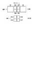
図7は、HOE25の屈折型対物レンズ26側の表面を拡大して示している。このように、HOE25には、各段の高さがdである4段の階段形状の斜面部を有する鋸波形状の凹凸が同心円状に偏心して形成されている。この凹凸は、光ディスク41Aの記録面上において、最適な光スポットサイズが得られるように、最適な径で(即ち、光ディスク41Aに対して最適なNAになるように)形成されている。
【0052】
即ち、HOE25の階段形状の段差部が形成されている範囲の径は、屈折型対物レンズ26のNAより小さい所定の値に設定されており、これにより、波長λ1の光(光ディスク41A)に対するNAが実質的に規定されている。なお、HOE25のコリメータレンズ24側の表面は平面を呈している。
【0053】
HOE25の階段形状のピッチは、波長λ1のレーザ光を厚さt1の基板を有する光ディスク41Aに照射した場合に、厚さt2の光ディスク41Bとの基板厚の違いにより発生する球面収差と、波長の違いにより発生する軸上色収差を補正する所望の回折角が得られる値に設定されている。
【0054】
また、HOE25の階段形状の段数Nと各段の高さd(段数Nと高さdでHOE25の高さ(深さ)((N−1)d)が規定される)は、レーザ光の波長λ1,λ2の値に応じて設定されている。すなわち、凹凸における階段形状の段数Nは、次の式
N0=λ1/(q×λ1−p×λ2)または
N0=λ1/(p×λ2−q×λ1)
(p,qは、所定の正の整数)
で算出されるN0の値(整数)に設定されている。あるいはまた、値N0の近傍の整数であって、波長λ1に対する0次光の回折効率(入射光の光量と出射光の光量の比)が、1次光または−1次光の回折効率より小さくなる場合の値に設定される。要するに、Nとλ1,λ2の関係は、完全に最適化せずとも、実用上問題のない回折効率と迷光量の小ささを実現することができる範囲で設定される。
【0055】
さらに、各段の高さdは、次の式
d0=p×λ2/(n−1)
(pは、所定の正の整数、nは、HOE25の屈折率)
で算出されるd0の値に設定されている(d=d0)。あるいはまた、値d0の近 傍の値であって、波長λ2に対する0次光の回折効率(入射光の光量と出射光の光量の比)が、1次光と−1次光の回折効率より大きくなる場合の値に設定される。
【0056】
例えば、整数p,qをp=1,q=1として算出された1段の高さがd0であ るN0段の凹凸を有するHOE25にレーザ光(平行光線)が入射した場合、H OE25は、各部の厚さに応じて、入射したレーザ光の位相を変化させる。第1の波長λ1のレーザ光が入射した場合、図8(a)に示すように、図7の領域Aを通過したレーザ光を基準として、図7の領域Bを通過したレーザ光には、約(3/2)πラジアンの位相差を与え、図7の領域Cを通過したレーザ光には、約(6/2)πラジアンの位相差を与え、図7の領域Dを通過したレーザ光には、約(9/2)πラジアンの位相差を与える。
【0057】
位相差は、2πラジアンの整数倍の位相を加減しても、元の位相差と等価であるので、図8(a)の位相差を図8(b)に示すように書き直すことができる。即ち、波長λ1のレーザ光がHOE25に入射した場合、領域Aを通過したレーザ光を基準として、領域Bを通過したレーザ光には、約(1/2)πラジアンの位相差が与えられ、領域Cを通過したレーザ光には、約πラジアンの位相差が与えられ、領域Dを通過したレーザ光には、約(3/2)πラジアンの位相差が与えられる。このように、波長λ1のレーザ光は、入射したHOE25の部位に応じて位相差が与えられるので回折する。
【0058】
一方、第2の波長λ2のレーザ光が入射した場合、図9(a)に示すように、図7の領域Aを通過したレーザ光を基準として、図7の領域Bを通過したレーザ光には、約2πラジアンの位相差が与えられ、図7の領域Cを通過したレーザ光には、約4πラジアンの位相差が与えられ、図7の領域Dを通過したレーザ光には、約6πラジアンの位相差が与えられる。
【0059】
上述したように、位相差は、2πラジアンの整数倍の位相を加減しても、元の位相差と等価であるので、図9(a)の位相差を図9(b)に示すように書き直すことができる。即ち、波長λ2のレーザ光がHOE25に入射した場合、領域A乃至領域Dのうち所定の領域を通過したレーザ光と、他の領域を通過したレーザ光の位相差はほぼゼロである。従って、波長λ2のレーザ光は、HOE25で実質的に回折せずに、そのまま透過する。
【0060】
このように、HOE2に対して、一方の波長λ1に対してパワーを持たせ、他方の波長λ2に対してパワーを持たせないようにすることで、それぞれの波長の光を異なる位置に集束させ、異なる種類の光ディスクを再生する場合における屈折型対物レンズ26の移動量(屈折型対物レンズ26の先端と光ディスクとの距離(ワーキングディスタンス)の差)を低減させる(例えば0.2mm以内にさせる)ことができる。
【0061】
また、屈折型対物レンズ26は波長λ2の光を光ディスク41Bに集光するのに最適化されているので、収差は発生しない。さらに、屈折型対物レンズ26と光ディスク41Aで発生する波長λ1の光に対する収差はHOE25で補正される。従って、いずれの波長の光も各光ディスク上に良好なスポット形状として集光させることができる。
【0062】
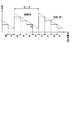
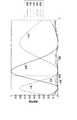
図10は、HOE25の回折効率(入射光の光量と出射光の光量の比)の一例を示している。このような特性は、回折部25Aの階段の段数を4段(4ステップ)とし、1段(1ステップ)の高さdを、650/(n−1)nmより若干低い方にシフトさせた状態に形成することで実現される。波長λ2においては、0次の回折光(即ち、透過光)の回折効率がほぼ90%を示しているので、第2の波長λ2のレーザ光は、その光量の90%が、0次の回折光としてHOE25を通過(透過)する。
【0063】
このように、HOE25を通過する際の第2の波長λ2のレーザ光の光量の減衰は、10%であるので、HOE25を2回(光ディスク41Bへ向かうときと、光ディスク41Bから反射してきたとき)通過しても、第2の波長λ2のレーザ光の光量は、約20%しか減衰せず、発生したレーザ光の光量の約80%を、光ディスクの再生または記録に利用することができる。
【0064】
一方、波長λ1においては、−1次の回折光の回折効率が約72%を示しているので、第1の波長λ1のレーザ光は、その光量が約72%に減衰して、−1次の回折光としてHOE25を所定の回折角だけ回折して通過する。
【0065】
このように、HOE25を通過する際、第1の波長λ1のレーザ光の光量は、約72%に減衰するので、HOE25を2回(光ディスク41Aへ向かうときと、光ディスク41Aから反射してきたとき)通過した後の第1の波長λ1のレーザ光の光量は、約52%(=0.72×0.72×100%)となるが、光ディスクの記録または再生には充分な光量である。
【0066】
なお、レーザチップ21A,21Bで発生するレーザ光の波長帯域は、充分狭く、実質的に単一波長の光と考えることができる。従って、HOE25で波長λ2の0次光を得ているとき、あるいは、波長λ1の−1次光を得ているとき、他の次数の不要な回折光は殆ど発生しない。従って、光のエネルギーの利用効率を向上させ、迷光の発生を抑制することができる。
【0067】
また、HOE25の表面の凹凸を3段(N=3)以上にすることにより、光の利用効率(回折効率)が良好なHOE25を作成することができ、特に、4段以上にすると、上述のようにレーザ光の利用効率(回折効率)が高くなる。2段にすると、レーザ光の利用効率(回折効率)が低くなるとともに、不要な1次の回折光が、再生または記録に利用される−1次の回折光と同じ回折効率で発生してしまい、迷光となるので好ましくない。
【0068】
さらに、2段だと、波長λ1とλ2の間隔が長くなり、波長λ1を780nmの近傍に、かつ、波長λ2を650nmの近傍に、それぞれ配置することが困難になる。4段にするとこれらの値の近傍に配置することができる。5段にした場合、波長λ1とλ2をそれぞれ780nmまたは650nmに最も近い値にすることができる。ただし、HOE25の4段の構造は、基板を2回マスキングしてエッチングすることにより製造することができるが、5段の構造は、金型などから製造することが必要となり、コスト高となる。
【0069】
次に、図2と図3の実施の形態の動作について説明する。入力装置5を操作して、DVD41Bの再生を指令すると、制御回路4は、光源切り換え用回路8を制御し、図2に示すように、レーザチップ21Bを駆動させ、波長650nmのレーザ光を発生させる。このレーザ光は、BS23を介して、コリメータレンズ24に入射され、平行光に変換される。コリメータレンズ24は、このレーザ光をHOE25に入射する。
【0070】
上述したように、HOE25は、入射光の殆ど(90%)をそのまま透過する。すなわち、図11に示すように、90%の0次回折光を出射する。屈折型対物レンズ26は、入射されたレーザ光を集束し、DVD41Bに照射させる。屈折型対物レンズ26は、0.6mmの厚さの基板を介して、この0次回折光がDVD4Bの記録面に照射されたとき発生する球面収差を補正するように適正化されている。従って、DVD41Bの記録面には、ほぼ回折限界まで集光された良好な光スポットが形成される。
【0071】
DVD41Bの記録面で反射されたレーザ光は、屈折型対物レンズ26により集光され、平行光としてHOE25に入射される。HOE25においては、図12に示すように、入射されたレーザ光を実質的にそのまま通過させる。すなわち、0次回折光を出射する。ここでも、90%の回折効率であるため、入射光と反射光の2回の回折のため、戻り光のエネルギーは、入射光のエネルギーの約80%(=0.9×0.9×100%)となる。
【0072】
この戻り光は、コリメータレンズ24により集束され、BS23に入射される。BS23は、入射された光を反射し、マルチレンズ27に出射する。マルチレンズ27は、入射されたレーザ光に非点収差を与えて、ホトディテクタ28に入射させる。
【0073】
ホトディテクタ28においては、このようにしてDVD41Bより反射されて戻ってきたレーザ光が、ホトディテクタ28Bで受光される。演算回路2は、受光素子64Aと64Cの出力の和と、受光素子64Bと64Dの出力の和の差((A+C)−(B+D))から、フォーカスエラー信号を生成する。また、それぞれの出力の和((A+B)+(C+D))と差((A+B)−(C+D))の位相差から、トラッキングエラー信号が生成される。さらに、受光素子64A乃至64Dの出力の和からデータ検出信号が生成される。
【0074】
制御回路4は、演算回路2より供給されたフォーカスエラー信号とトラッキングエラー信号に対応して、それぞれフォーカスサーボ用アクチュエータ6とトラッキングサーボ用アクチュエータ7を制御し、フォーカスサーボとトラッキングサーボを制御する。
【0075】
また、データ検出信号は、再生回路3に入力され、復調された後、再生信号として図示せぬ回路に出力される。
【0076】
一方、入力装置5を制御して、CD41Aの再生を指令すると、制御回路4は、光源切り換え用回路8を制御し、図3に示すように、レーザチップ21Aを駆動し、波長を780nmのレーザ光を出射させる。このレーザ光は、グレーティング22Aに入射され、実質的に3本のレーザ光に分割される(3ビーム法によるトラッキング制御のため)。そして、この3本のレーザ光は、BS23、コリメータレンズ24を介して、HOE25に入射される。
【0077】
レーザチップ21Aは、屈折型対物レンズ26の光軸外に配置されているので、このレーザ光は、HOE25に光軸外から入射される。そこで、図13に示すように、このHOE25は、入射されたレーザ光を回折し、入射光の約70%のエネルギーの−1次回折光を光軸上の光として出射する。
【0078】
この−1次回折光は、屈折型対物レンズ26により集束され、1.2mmの厚さを有する基板を介して、CD41Aの情報記録面上に集束、照射される。屈折型対物レンズ26は、厚さが0.6mmの基板を有するDVD41Bを再生する場合に、球面収差が相殺されるように最適化が行われている。従って、1.2mmの厚さの基板を有するCD41Aを再生する場合、球面収差が発生してしまう。HOE25は、この球面収差も補正するように設計されている。また、HOE25は、光軸外から入射されてきた光を、光軸上の光として出射する場合に発生するコマ収差を補正するように設計されている。従って、CD41Aの情報記録面上には、レーザ光が、その回折限界まで集光され、最適な光スポットが形成される。
【0079】
CD41Aの情報記録面で反射されたレーザ光は、屈折型対物レンズ26により集光され、HOE25に入射される。図14に示すように、HOE25においては、CD41Aの情報記録面上のデータにより変調されたレーザ光が回折され、−1次回折光として再び光軸外に出射される。この場合にも、−1次回折光は、CD41Aから入射された反射光の約70%のエネルギーのものとなるから、結局、レーザチップ21Aより出射されたレーザ光のエネルギーの約49%(=0.7×0.7×100%)が利用されることになる。
【0080】
HOE25より出射されたレーザ光は、図3に示すように、光軸外の光路上をコリメータレンズ24に入射され、集束された後、BS23に入射され、そこで反射され、マルチレンズ27に入射される。さらに、マルチレンズ27で非点収差が与えられたレーザ光は、ホトディテクタ28に入射される。
【0081】
ホトディテクタ28においては、このレーザ光が、図4に示すホトディテクタ28Aで受光される。グレーティング22Aで3本に分割されたレーザ光のうち、中央のレーザ光の反射光は、受光素子63で受光され、その前後に配置されている2つのレーザ光は、受光素子61と受光素子62で、それぞれ受光される。演算回路2は、受光素子61の出力と62の出力の差からトラッキングエラー信号を生成し、受光素子63Aの出力と63Cの出力の和と、受光素子63Bと63Dの出力の和の差から、フォーカスエラー信号を生成する。また、受光素子63A乃至63Dの出力の和から、データ検出信号を生成する。
【0082】
屈折型対物レンズ26の有効瞳半径は、DVD41Bを再生する場合に最適なNA(NA=0.6)が得られるように定められている。これに対して、CD41Aの最適なNAは、約0.45とされている。そこで、この最適なNAが得られるように、HOE25の回折部25Aの形成されている領域は、屈折型対物レンズ26の有効瞳領域より狭い範囲とされている。その結果、図13に示すように、回折部25Aの外周の回折部25Aが形成されていない領域を透過したレーザ光が、不要光としてCD41Aに入射され、その反射光が、図14に示すように、再び戻ってきて、その一部がホトディテクタ28Aに入射され、サーボ信号などに若干の影響を及ぼすおそれがある。しかしながら、その光量は小さく、またその光は、大きな収差を有するものであるため、実用上殆ど無視することが可能である。
【0083】
図2と図3に示した構成を、図32と図33に示した構成と比較して明らかなように、本実施の形態においては、レーザチップ21Bを屈折型対物レンズ26の光軸上に配置し、レーザチップ21Aを光軸外に配置し、その光軸外に配置したレーザチップ21Aからのレーザ光を、HOE25で光軸上に案内するようにしたので、図32と図33に示した光路合成(光軸分割)のためのダイクロイックプリズム113が不要となる。その結果、部品点数を少なくすることができるだけでなく、図32と図33に示すように、2つの放射光源111Aと111Bの両方を光軸上に配置するようにすると、それぞれをほぼ垂直な関係に配置しなければならなくなるため、装置が大型化してしまうことになるが、2つの光源のうちの一方を光軸外に配置するようにしたので、2つを比較的近接して1つのパッケージ内に配置することができ、より小型化が可能となる。
【0084】
図15と図16は、図2と図3に示した光学ピックアップ部をさらに小型化した場合の構成を示している。図15は、DVD41B再生時の光路を示し、図16は、CD41A再生時の光路を示している。この構成例においては、図2と図3におけるグレーティング22A、BS23、コリメータレンズ24、およびマルチレンズ27が省略された構成とされている。そして、さらに、レーザチップ21A,21Bと、ホトディテクタ28が複合レーザカップラ(LC)71としてまとめられた構成とされている。
【0085】
そして、CD41Aを再生する場合には、フォーカスエラー信号は、差動同心円法により生成され、トラッキングエラー信号は、プッシュプル法(トップホールドプッシュプル法)により生成される。また、DVD41Bを再生する場合には、フォーカスエラー信号は、CDを再生する場合と同様に、差動同心円法により生成されるが、トラッキングエラー信号は、DPD法により生成される。
【0086】
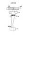
図17は、複合LC71の外観構成を示し、図18は、複合LC71の断面構成を表している。
【0087】
これらの図に示すように、レーザチップ21Aと21Bは、ベース72に所定の距離を隔てて固定されている。そして、これらのレーザチップ21Aと21Bより出射されたレーザ光は、マイクロプリズム73の面73Aで反射されて、HOE25、屈折型対物レンズ26を介して、CD41AまたはDVD41Bに照射される。
【0088】
そして、これらのCD41AまたはDVD41Bより反射されたレーザ光が、屈折型対物レンズ26、HOE25を介して、複合LC71のマイクロプリズム73に入射される。そして、この入射されたレーザ光は、面73Aからマイクロプリズム73の内部に進入し、マイクロプリズム73の底面に配置されているホトディテクタ28−1上に照射される。また、その一部の光は、ホトディテクタ28−1で反射され、マイクロプリズム73の上面73Bの結像点で結像される。この結像点は、発光点としてのレーザチップ21A,21Bと共役な関係の位置にある。そして、結像点で(上面73Bで)反射されたレーザ光が、さらにマイクロプリズム73の底面に設けられているもう1つのホトディテクタ28−2に入射される。
【0089】
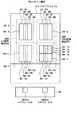
図19は、マイクロプリズム73の底面に取り付けられているホトディテクタ28−1と28−2の上面から見た構成を示している。同図に示すように、CD信号検出用のホトディテクタ28Aは、ホトディテクタ28−1を構成する受光素子60−1と、ホトディテクタ28−2を構成する受光素子60−2により構成されている。これらの受光素子60−1と60−2は、それぞれ受光素子60−1A乃至60−1Dと、受光素子60−2A乃至60−2Dの4つに分割されている。
【0090】
DVD信号検出用のホトディテクタ28Bは、ホトディテクタ28−1を構成する受光素子64−1とホトディテクタ28−2を構成する受光素子64−2により構成されている。受光素子64−1は、受光素子64−1A乃至64−1Hに8分割されており、受光素子64−2は、受光素子64−2A乃至64−2Dに4分割されている。
【0091】
演算回路2は、CD信号検出用のホトディテクタ28Aの出力から差動同心円法に基づいてフォーカスエラー信号を生成する場合、次式を演算する。
F1=(B+C)−(A+D)
F2=(G+F)−(E+H)
F2=F1−F2={(B+C)−(A+D)}−{(G+F)−(E+H)}
【0092】
ジャストフォーカス状態のとき、これらの信号F1乃至F3は、いずれも0となり、ディスクニアのとき、F1とF3は、負となり、F2は、正となる。これに対して、ディスクファーのとき、F1とF3は、正となり、F2は、負となる。
【0093】
プッシュプル方式のトラッキングエラー信号Tは、次式から演算される。
T=(A+B+E+F)−(C+D+G+H)
【0094】
一方、DVD再生時における差動同心円法に基づくフォーカスエラー信号は、CD再生時における場合と同様に、次のように演算される。
また、DVD再生時においてDPD法によりトラッキングエラー信号を生成する場合、演算回路2は、次式を演算する。
P=A+B
Q=C+D
R=c+d
S=a+b
【0096】
そして、さらに、(P+S)+(Q+R)と、(P+S)−(Q+R)の位相差を検波することで、トラッキングエラー信号が生成される。
【0097】
図20と図21は、光ピックアップ部1のさらに他の構成例を示している。図20は、DVD再生時における光路を示しており、図21は、CD再生時における光路を表している。その基本的な構成は、図2と図3に示した場合と同様であるが、HOE25の特性と、ホトディテクタ28のパターンの構成が、図2と図3に示した場合と異なっている。
【0098】
図22は、図20と図21に示すHOE25の回折効率を示している。この場合においては、1段の高さdは、650/(n−1)nmより若干高い側にシフトされている。この場合においては、650nmの波長のレーザ光が入射された場合、約87%の光は0次回折光としてそのまま出射される。その他の次数の回折光は、0次回折光に較べて、その強度が充分小さくなっている。
【0099】
また、波長が780nmのレーザ光が入射された場合には、その40%程度の光が、−1次回折光としてHOE25により回折を受け、40%程度の光は、0次回折光として、そのままHOE25を透過する。その他の次数の光は、0次回折光または−1次回折光に較べて充分小さくなっている。この場合、CDの光スポットとDVDの光スポットが光学的に同一位置となるように、輪帯形状を最適化し、同一のホトディテクタで信号を検出することができる。
【0100】
図23は、図20と図23に示すホトディテクタ28の受光素子のパターンを示している。同図に示すように、この例においては、ホトディテクタ28は、図4に示したCDのレーザ光検出用のホトディテクタ28Aと実質的に同一に形成されている。そして、このホトディテクタ28は、CD用のレーザ光だけでなく、DVD用のレーザ光も受光するようになされている。
【0101】
図20に示すように、DVD41Bを再生している場合には、レーザチップ21Bより出射された650nmの波長の光がHOE25に入射されると、その約87%の光が、0次回折光として、屈折型対物レンズ26を介して、DVD41Bに入射される。DVD41Bで反射されたレーザ光は、屈折型対物レンズ26により集束され、再びHOE25に入射される。この場合も、入射されたレーザ光のうち、約87%のレーザ光が、0次回折光として、そのまま出射される。従って、結局、約76%の光が再生に利用されることになる。
【0102】
HOE25より出射されたレーザ光は、コリメータレンズ24、PB23、マルチレンズ27を介して、ホトディテクタ28の受光素子63に入射される。演算回路2は、受光素子63A乃至63Cの出力から、非点収差法に基づいて、フォーカスエラー信号を演算し、DPD法に基づいて、トラッキングエラー信号を生成する。
【0103】
一方、図21に示すように、780nmのレーザ光がレーザチップ21Aより出射されると、このレーザ光は、グレーティング22Aにより、実質的に3つに分割され、PB23、コリメータレンズ24を介して、HOE25に入射される。HOE25では、図24に示すように、光軸外から入射されたレーザ光のうち、その40%が、−1次回折光として、光軸上に出射され、その約40%が、0次回折光として、そのまま光軸外に出射される。−1次回折光は、HOE25が、コマ収差や非点収差、並びにディスク基板の厚さの違いによる球面収差などを相殺するように最適化されているため、屈折型対物レンズ26を介して、CD41A上に、収差のない良好な光スポットを形成する。なお、このスポットの位置は、DVD用のレーザチップ21Bの発光点と共役な位置になるように定めておく。
【0104】
HOE25より出射された−1次回折光は、屈折型対物レンズ26を介して、CD41Aに入射され、そこに記録されている記録データに対応して変調される。その変調光が、CD41Aで反射され、屈折型対物レンズ26で集束されて、再びHOE25に入射される。このとき、図25に示すように、HOE25では、入射された光の40%が、−1次回折光として、光軸外に出射され、その40%が、0次回折光として、そのまま光軸上を透過する。この0次回折光は、コリメータレンズ24、BP23、マルチレンズ27を介して、ホトディテクタ28に入射される。いまの場合、グレーティング22Aにより、光は、実質的に3本に分割されているので、それぞれが受光素子61乃至63により受光される。そして、演算回路2により、フォーカスエラー信号は、非点収差法に基づいて演算され、トラッキングエラー信号は、3ビーム法の原理により生成される。
【0105】
この例においては、HOE25を透過し、再生用の光として利用される光のエネルギーは、CD41Aに入射される光の約16%(=0.4×0.4×100%)となる。
【0106】
図24に示すように、光軸外から入射したレーザ光の40%が0次回折光として、そのままHOE25を透過する。また、HOE25の回折部25Aの外周を透過する光もある。これらの光は、いずれも不要光となるが、その一部は、CD41Aで反射され、図25に示すように、再びHOE25に入射される。HOE25を0次回折光として透過した光の反射光は、HOE25において、再び入射された成分の40%が、0次回折光として、そのままHOE25を透過し、その40%が、−1次回折光として、HOE25より出射される。しかしながら、これらの成分は、いずれも光軸外の成分であるため、ホトディテクタ28には入射されない。また、回折部25Aの外周を透過した成分もホトディテクタ28には入射されないので、これらの信号によりサーボ信号などが悪影響を受けるおそれは少ない。
【0107】
この構成例によれば、上述した図2と図3の構成例より、光量は少なくなるが、迷光も少なくなり、また、ホトディテクタのパターンを簡略化することが可能となる。その結果、より小型化が可能となる。
【0108】
図26と図27は、図20と図21に示した光ピックアップ部をより簡略化した場合の構成例を示している。図26は、DVD再生時の光路を表し、図27は、CD再生時の光路を表している。この構成例においても、図20と図21におけるPB23、コリメータレンズ24、およびマルチレンズ27が省略されて、レーザチップ21A,21Bとホトディテクタ28が、複合LC71として、1つのパッケージ内に収容されている。
【0109】
図28は、複合LC71におけるホトディテクタ28のパターンを表している。このパターンは、図19に示したDVD信号検出用ホトディテクタ28Bと実質的に同一の構成とされている。但し、図28に示すパターンでは、DVD用の光だけではなく、CD用の光も受光される。演算回路2は、フォーカスエラー信号は、CD再生時における場合も、DVD再生時における場合も、差動同心円法に基づき求めるが、トラッキングエラー信号は、CD再生時には、プッシュプル法による演算から生成し、DVD再生時には、DPD法による演算から生成する。
【0110】
このように構成することで、図19に示した場合に較べて、CD信号検出用のホトディテクタ28Aが不要となる分、さらに小型化することが可能となる。
【0111】
なお、本発明は、再生だけでなく、情報を記録する場合にも適用が可能である。
【0112】
【発明の効果】
以上のごとく、請求項1に記載の記録再生装置によれば、異なる長さの波長の光を発生する発生手段の一方を光軸上に配置し、他方を光軸外に配置するようにし、光軸外から入射される光のコマ収差を補正するようにしたので、DVDだけでなく、CD−Rを含むCDを再生することが可能な、より小型の装置を実現することができる。
【図面の簡単な説明】
【図1】本発明の記録再生装置の一実施の形態の構成例を示すブロック図である。
【図2】図1の実施の形態の光ピックアップ部1の構成例を示す図である。
【図3】図1の実施の形態の光ピックアップ部1の構成例を示す図である。
【図4】図2のホトディテクタ28の受光素子のパターンを示す図である。
【図5】図2のホログラフィック光学素子25の構成例を示す図である。
【図6】球面収差とコマ収差の補正を説明する図である。
【図7】図2のホログラフィック光学素子25の一例の一部を拡大した断面図である。
【図8】図2のホログラフィック光学素子25を通過した波長λ1のレーザ光の位相特性の一例を示す図である。
【図9】図2のホログラフィック光学素子25を通過した波長λ2のレーザ光の位相特性の一例を示す図である。
【図10】図2のホログラフィック光学素子25の回折効率特性を示す図である。
【図11】図2のホログラフィック光学素子25に第2の波長のレーザ光が入射した場合の動作を説明する図である。
【図12】図2のホログラフィック光学素子25にディスクからの反射光が入射した場合の動作を説明する図である。
【図13】図3のホログラフィック光学素子25に光軸外から光が入射した場合の動作を説明する図である。
【図14】図3のホログラフィック光学素子25にディスクからの反射光が入射された場合の動作を説明する図である。
【図15】図1の実施の形態の光ピックアップ部1の他の構成例を示す図である。
【図16】図1の実施の形態の光ピックアップ部1の他の構成例を示す図である。
【図17】図15の複合LC71の外観の構成を示す斜視図である。
【図18】図15の複合LC71の内部の構成を示す断面図である。
【図19】図15の複合LC71におけるホトディテクタ28のパターンを示す図である。
【図20】図1の実施の形態の光ピックアップ部1のさらに他の構成例を示す図である。
【図21】図1の実施の形態の光ピックアップ部1のさらに他の構成例を示す図である。
【図22】図20のホログラフィック光学素子25の回折効率特性を示す図である。
【図23】図20のホトディテクタ28の受光素子のパターンを示す図である。
【図24】図21のホログラフィック光学素子25に光軸外からの光が入射されたときの動作を説明する図である。
【図25】図21のホログラフィック光学素子25のディスクからの反射光が入射された場合の動作を説明する図である。
【図26】図1の実施の形態の光ピックアップ部1のさらに他の構成例を示す図である。
【図27】図1の実施の形態の光ピックアップ部1のさらに他の構成例を示す図である。
【図28】図26の複合LC71における受光素子のパターンを示す図である。
【図29】従来の二重焦点ホログラフィック光学素子の光路を説明する図である。
【図30】図29のホログラフィック光学素子101の構成を示す図である。
【図31】図29のホログラフィック光学素子101に光が入射された場合の動作を説明する図である。
【図32】従来の光ピックアップ部の構成例を示す図である。
【図33】従来の光ピックアップ部の構成例を示す図である。
【図34】図32のホログラフィック光学素子117の動作を説明する図である。
【図35】図33のホログラフィック光学素子117の動作を説明する図である。
【符号の説明】
1 光学ピックアップ部, 2 演算回路, 3 再生回路, 4 制御回路, 5 入力装置, 6 フォーカスサーボ用アクチュエータ, 7 トラッキングサーボ用アクチュエータ, 8 光源切り換え用回路, 9 モータ, 21A,21B レーザチップ, 22A グレーティング, 23 ビームスプリッタ(BS), 24 コリメータレンズ, 25 ホログラフィック光学素子(HOE), 26 屈折型対物レンズ, 28 ホトディテクタ(PD),
41A CD, 41B DVD[0001]
BACKGROUND OF THE INVENTION
The present invention records and reproducesapparatus In particular, when information is recorded on or reproduced from different recording media using light of the first wavelength and light of the second wavelength, the recording / reproduction can be further reduced in size.apparatus About.
[0002]
[Prior art]
As recording media for recording or reproducing information using light, optical discs such as compact disc (CD) (trademark), CD-ROM, and CD-R are widely used. New recording media such as a DVD (Digital Versatile Disc) for recording data are being developed.
[0003]
When reading digital information from such an optical disc, laser light is condensed on a recording medium, reflected light from the recording medium is detected, and the level of the reflected light is converted into binary data.
[0004]
In a high-density optical disk, a short wavelength laser beam is used (for example, when reproducing a CD, the wavelength λ is λ = 780 nm, and when reproducing a DVD on which data is recorded at a higher density, λ = 635 to 650 nm) and an objective lens having a large numerical aperture (NA) (for example, NA is 0.45 when reproducing a CD and NA = 0.6 when reproducing a DVD) Is used to converge the laser beam to a narrower range, receive the reflected light, and reproduce the recorded information.
[0005]
When such an objective lens having a large numerical aperture (NA) is used, the amount of aberration in the reflected light increases due to the inclination (skew) of the optical disk. The amount of aberration in reflected light is reduced, compared with 1.2 mm of DVD (0.6 mm for DVD).
[0006]
As described above, according to the difference in the size of the condensing spot (proportional to λ / NA) defined according to the NA of the objective lens and the wavelength λ of the laser light, and the thickness of the substrate of the optical disk Due to the difference in the amount of spherical aberration that occurs, it is difficult to use an optical system for reading information recorded on a conventional CD as it is for reproduction of a DVD, and conversely, an optical system designed for a DVD is used. It is difficult to directly use it for CD reproduction.
[0007]
However, it is considered that conventional optical discs such as CDs and high-density optical discs such as DVDs will coexist in the future, so when reproducing these optical discs, a dedicated playback device is prepared for each type of optical disc. If it must be, it is inconvenient.
[0008]
Thus, several methods for reproducing a plurality of optical discs having different recording densities and different substrate thicknesses with one apparatus have been proposed.
[0009]
As one of them, a method of combining an objective lens and a holographic optical element (HOE) is disclosed, for example, in JP-A-7-98431. FIG. 29 shows the principle of the technique described in the publication. That is, as shown in the figure, for example, a laser beam having a wavelength of 650 nm is applied to the
[0010]
The
[0011]
Further, the ring pitch of the
[0012]
However, in such a pickup, since the wavelength used is as short as 650 nm, a normal CD can be reproduced, but a CD-R cannot be reproduced. That is, a CD-R that can be written as well as reproduced is formed so as to reflect a wavelength in a band of 780 nm, and a wavelength of 650 nm used in a DVD is almost absorbed.
[0013]
Accordingly, the present applicant has proposed a pickup capable of reproducing both a CD and a DVD including a CD-R, for example, as Japanese Patent Application No. 8-121337. 32 and 33 show an example of the configuration. FIG. 32 shows the optical system when reproducing the
[0014]
When reproducing the
[0015]
That is, as shown in an enlarged view in FIG. 34, the HOE 117 transmits almost 100% of the laser beam having a wavelength of 650 nm. That is, 0th order diffracted light is emitted from the
[0016]
On the other hand, when reproducing the
[0017]
As shown in FIG. 35, the ring pitch of the
[0018]
The laser beam reflected by the
[0019]
[Problems to be solved by the invention]
However, in the previously proposed invention, the two
[0020]
The present invention has been made in view of such a situation, and allows a CD-R to be reproduced and further miniaturized.
[0021]
[Means for Solving the Problems]
The recording / reproducing apparatus according to
[0023]
2. The recording / reproducing apparatus according to
[0024]
DETAILED DESCRIPTION OF THE INVENTION
Embodiments of the present invention will be described below, but in order to clarify the correspondence between each means of the invention described in the claims and the following embodiments, in parentheses after each means, The features of the present invention will be described with the corresponding embodiment (however, an example) added. However, of course, this description does not mean that each means is limited to the description.
[0025]
The recording / reproducing apparatus according to
[0028]
FIG. 1 shows a configuration example of an embodiment of a recording / reproducing apparatus of the present invention. In this embodiment, the
[0029]
The arithmetic circuit 2 calculates a data detection signal (RF signal) for reproducing an optical disk from a PD output signal (signal of each light receiving unit), a focus error signal indicating a laser beam focus shift in the optical axis direction, and a radius of the optical disk. A tracking error signal indicating a direction tracking deviation is calculated, a data detection signal is output to the
[0030]
The
[0031]
The
[0032]
When the
[0033]
The
[0034]
Note that when the
[0035]
2 and 3 show a configuration example of the
[0036]
The
[0037]
The
[0038]
The
[0039]
When the wavelength of the laser light incident from the
[0040]
The
[0041]
Furthermore, as described above, the refractive
[0042]
The
[0043]
The refractive
[0044]
The
[0045]
FIG. 4 shows a configuration example of the pattern of the
[0046]
On the other hand, during DVD reproduction, the tracking is performed by the differential phase detection (DPD) method and the focus control is performed by the astigmatism method, so that the
[0047]
Further, the arithmetic circuit 2 obtains the CD data detection signal from the sum of the outputs of the
[0048]
Here, the
φs = C1 r2 + C2 rFour + CThree r6 + CFour r8 + ...
Where r2 ≡ ≠ x2 + Y2 And C1 , C2 , ... are constants.
[0049]
On the other hand, the phase difference function φg of the
φg = C0 y
C0 Is a constant.
[0050]
Therefore, as shown in FIG. 6C, the
FIG. 7 shows an enlarged surface of the
[0052]
That is, the diameter of the range in which the stepped step portion of the
[0053]
The pitch of the staircase shape of the
[0054]
Further, the number of steps N of the step shape of the
N0 = Λ1 / (q × λ1−p × λ2) or
N0 = Λ1 / (p × λ2-q × λ1)
(P and q are predetermined positive integers)
N calculated by0 Is set to an integer (integer). Alternatively, the value N0 And the value when the diffraction efficiency of the 0th-order light (ratio of the amount of incident light and the amount of outgoing light) with respect to the wavelength λ1 is smaller than the diffraction efficiency of the first-order light or −1st-order light. Is set. In short, the relationship between N and λ1 and λ2 is set within a range in which diffraction efficiency and a small amount of stray light can be realized without causing any practical problems without being completely optimized.
[0055]
Further, the height d of each step is given by
d0 = P × λ2 / (n−1)
(P is a predetermined positive integer, n is the refractive index of HOE 25)
D calculated by0 (D = d0 ). Alternatively, the value d0 The value when the diffraction efficiency of the 0th-order light (ratio of the amount of incident light to the amount of emitted light) with respect to the wavelength λ2 is greater than the diffraction efficiency of the first-order light and −1st-order light. Set to
[0056]
For example, the height of one step calculated by using integers p and q as p = 1 and q = 1 is d0 N0 When a laser beam (parallel light beam) is incident on the
[0057]
Even if the phase difference is an integer multiple of 2π radians, the phase difference is equivalent to the original phase difference. Therefore, the phase difference in FIG. 8A can be rewritten as shown in FIG. 8B. That is, when a laser beam having a wavelength λ1 is incident on the
[0058]
On the other hand, when a laser beam having the second wavelength λ2 is incident, as shown in FIG. 9A, the laser beam that has passed through the region B in FIG. Is given a phase difference of about 2π radians, a laser beam having passed through region C in FIG. 7 is given a phase difference of about 4π radians, and a laser beam having passed through region D in FIG. A phase difference in radians is given.
[0059]
As described above, the phase difference is equivalent to the original phase difference even if the phase is an integer multiple of 2π radians. Therefore, the phase difference in FIG. 9A is shown in FIG. 9B. Can be rewritten. That is, when the laser beam having the wavelength λ2 is incident on the
[0060]
In this way, the HOE 2 is given power to one wavelength λ1 and is not given power to the other wavelength λ2, thereby converging light of each wavelength at different positions. The amount of movement of the refractive objective lens 26 (difference in distance (working distance) between the tip of the refractive
[0061]
Further, since the refractive
[0062]
FIG. 10 shows an example of the diffraction efficiency (the ratio of the amount of incident light to the amount of emitted light) of the
[0063]
Thus, since the attenuation of the light amount of the laser light having the second wavelength λ2 when passing through the
[0064]
On the other hand, at the wavelength λ1, since the diffraction efficiency of the −1st order diffracted light is about 72%, the laser light of the first wavelength λ1 is attenuated to about 72%, and the −1st order Diffracted light passes through the
[0065]
As described above, when passing through the
[0066]
It should be noted that the wavelength band of the laser light generated by the
[0067]
Further, by making the unevenness of the surface of the
[0068]
Furthermore, if there are two stages, the interval between the wavelengths λ1 and λ2 becomes long, and it becomes difficult to dispose the wavelength λ1 in the vicinity of 780 nm and the wavelength λ2 in the vicinity of 650 nm. If the number of stages is four, it can be arranged in the vicinity of these values. In the case of five stages, the wavelengths λ1 and λ2 can be set to values closest to 780 nm or 650 nm, respectively. However, the four-stage structure of the
[0069]
Next, the operation of the embodiment of FIGS. 2 and 3 will be described. When the reproduction of the
[0070]
As described above, the
[0071]
The laser light reflected by the recording surface of the
[0072]
This return light is focused by the
[0073]
In the
[0074]
The
[0075]
The data detection signal is input to the
[0076]
On the other hand, when the
[0077]
Since the
[0078]
The minus first-order diffracted light is focused by the refractive
[0079]
The laser beam reflected by the information recording surface of the
[0080]
As shown in FIG. 3, the laser light emitted from the
[0081]
In the
[0082]
The effective pupil radius of the refractive
[0083]
As is clear by comparing the configuration shown in FIGS. 2 and 3 with the configuration shown in FIGS. 32 and 33, in this embodiment, the
[0084]
FIGS. 15 and 16 show the configuration when the optical pickup unit shown in FIGS. 2 and 3 is further miniaturized. FIG. 15 shows the optical path when reproducing the
[0085]
When reproducing the
[0086]
FIG. 17 shows an external configuration of the
[0087]
As shown in these drawings, the
[0088]
Then, the laser light reflected from the
[0089]
FIG. 19 shows a configuration of the photodetectors 28-1 and 28-2 attached to the bottom surface of the
[0090]
The
[0091]
The arithmetic circuit 2 calculates the following equation when generating a focus error signal from the output of the
F1 = (B + C)-(A + D)
F2 = (G + F)-(E + H)
F2 = F1 -F2 = {(B + C)-(A + D)}-{(G + F)-(E + H)}
[0092]
In the just focus state, these signals F1 To FThree Are all 0, and F1 And FThree Becomes negative and F2 Is positive. On the other hand, when disc fur, F1 And FThree Becomes positive and F2 Is negative.
[0093]
The push-pull tracking error signal T is calculated from the following equation.
T = (A + B + E + F) − (C + D + G + H)
[0094]
On the other hand, the focus error signal based on the differential concentric circle method at the time of DVD playback is calculated as follows, similarly to the case of CD playback.
When generating a tracking error signal by the DPD method during DVD reproduction, the arithmetic circuit 2 calculates the following expression.
P = A + B
Q = C + D
R = c + d
S = a + b
[0096]
Further, a tracking error signal is generated by detecting the phase difference between (P + S) + (Q + R) and (P + S) − (Q + R).
[0097]
20 and 21 show still another configuration example of the
[0098]
FIG. 22 shows the diffraction efficiency of the
[0099]
Further, when a laser beam having a wavelength of 780 nm is incident, about 40% of the light is diffracted by the
[0100]
FIG. 23 shows a pattern of the light receiving element of the
[0101]
As shown in FIG. 20, when reproducing the
[0102]
The laser light emitted from the
[0103]
On the other hand, as shown in FIG. 21, when 780 nm laser light is emitted from the
[0104]
The −1st order diffracted light emitted from the
[0105]
In this example, the energy of light transmitted through the
[0106]
As shown in FIG. 24, 40% of the laser light incident from outside the optical axis passes through the
[0107]
According to this configuration example, the amount of light is reduced but stray light is reduced as compared with the configuration examples of FIGS. 2 and 3 described above, and the pattern of the photodetector can be simplified. As a result, the size can be further reduced.
[0108]
FIGS. 26 and 27 show configuration examples in the case where the optical pickup unit shown in FIGS. 20 and 21 is further simplified. FIG. 26 shows the optical path during DVD playback, and FIG. 27 shows the optical path during CD playback. Also in this configuration example, the
[0109]
FIG. 28 shows the pattern of the
[0110]
With this configuration, it is possible to further downsize the
[0111]
The present invention can be applied not only to reproduction but also to recording information.
[0112]
【The invention's effect】
As described above, the recording / reproduction according to
[Brief description of the drawings]
FIG. 1 is a block diagram showing a configuration example of an embodiment of a recording / reproducing apparatus of the present invention.
2 is a diagram illustrating a configuration example of an
3 is a diagram illustrating a configuration example of the
4 is a diagram showing a pattern of a light receiving element of the
FIG. 5 is a diagram illustrating a configuration example of the holographic
FIG. 6 is a diagram illustrating correction of spherical aberration and coma aberration.
7 is an enlarged cross-sectional view of a part of an example of the holographic
8 is a diagram illustrating an example of phase characteristics of laser light having a wavelength λ1 that has passed through the holographic
9 is a diagram illustrating an example of phase characteristics of laser light having a wavelength of λ 2 that has passed through the holographic
10 is a diagram showing a diffraction efficiency characteristic of the holographic
11 is a diagram for explaining the operation when a laser beam having a second wavelength is incident on the holographic
12 is a diagram for explaining the operation when the reflected light from the disk is incident on the holographic
13 is a diagram illustrating an operation when light is incident on the holographic
14 is a diagram for explaining the operation when the reflected light from the disk is incident on the holographic
15 is a diagram illustrating another configuration example of the
16 is a diagram illustrating another configuration example of the
FIG. 17 is a perspective view showing an external configuration of the
18 is a cross-sectional view showing an internal configuration of the
19 is a diagram showing a pattern of the
20 is a diagram illustrating still another configuration example of the
FIG. 21 is a diagram illustrating still another configuration example of the
22 is a diagram showing a diffraction efficiency characteristic of the holographic
FIG. 23 is a view showing a pattern of a light receiving element of the
24 is a diagram for explaining the operation when light from outside the optical axis is incident on the holographic
FIG. 25 is a diagram for explaining the operation when the reflected light from the disk of the holographic
FIG. 26 is a diagram illustrating still another configuration example of the
FIG. 27 is a diagram showing still another configuration example of the
28 is a diagram showing a pattern of light receiving elements in the
FIG. 29 is a diagram for explaining an optical path of a conventional double-focus holographic optical element.
30 is a diagram showing a configuration of the holographic
31 is a diagram for explaining the operation when light is incident on the holographic
FIG. 32 is a diagram illustrating a configuration example of a conventional optical pickup unit.
FIG. 33 is a diagram illustrating a configuration example of a conventional optical pickup unit.
34 is a diagram for explaining the operation of the holographic
35 is a diagram for explaining the operation of the holographic
[Explanation of symbols]
DESCRIPTION OF
41A CD, 41B DVD
Claims (1)
Translated fromJapanese前記第1の長さの波長の光または第2の長さの波長の光を、前記第1の記録媒体または第2の記録媒体に集束して照射する集束手段と、
前記集束手段の光軸外に配置され、前記第1の長さの波長の光を発生する第1の発生手段と、
前記集束手段の光軸上であって、かつ前記第1の発生手段の近傍に配置され、前記第2の長さの波長の光を発生する第2の発生手段と、
前記第1の長さの波長の光を、そのコマ収差を補正して、前記集束手段の光軸上に案内する補正手段と、
前記第1の記録媒体または第2の記録媒体により反射された第1の長さの波長の光または第2の長さの波長の光を受光する受光手段とを備え、
前記補正手段は、前記第1の長さの波長の光の球面収差も補正するホログラフィック光学素子であり、前記第1の長さの波長の光に位相差を与え、前記第2の長さの波長の光には実質的に位相差を与えない高さの5段以上の階段形状を有する鋸波形状の凹凸が、前記光軸との交点に対し偏心した点を中心とする同心円状に形成された位相変調手段を有する
ことを特徴とする記録再生装置。A first recording medium having a substrate having a different thickness and on which information is recorded or reproduced by light having a first length of wavelength, and information is recorded or reproduced by light having a second length of light. In a recording / reproducing apparatus for recording or reproducing information with respect to the second recording medium,
Focusing means for focusing and irradiating the first recording medium or the second recording medium with the light having the first length or the light having the second length;
First generating means disposed outside the optical axis of the focusing means and generating light of the wavelength of the first length;
A second generator configured to generate light having a wavelength of the second length, disposed on the optical axis of the focusing unit and in the vicinity of the first generator;
Correction means for correcting the coma aberration of the light having the wavelength of the first length and guiding the light on the optical axis of the focusing means;
Light receiving means for receiving light having a first wavelength or light having a second wavelength reflected by the first recording medium or the second recording medium;
The correction means is a holographic optical element that corrects also the spherical aberration of the light having the first length, and gives a phase difference to the light having the first length, and the second length. Sawtooth-shaped irregularities having a stepped shape of5 or moresteps that do not substantially give a phase difference to light of a wavelength of λ areconcentrically centered on a point decentered with respect to the intersection with the optical axis A recording / reproducing apparatus comprising the formed phase modulation means.
Priority Applications (3)
| Application Number | Priority Date | Filing Date | Title |
|---|---|---|---|
| JP06585097AJP3653923B2 (en) | 1997-03-19 | 1997-03-19 | Recording / reproducing apparatus and method |
| US09/039,479US6084843A (en) | 1997-03-19 | 1998-03-16 | Optical recording and reproducing apparatus and method |
| KR1019980009213AKR100543422B1 (en) | 1997-03-19 | 1998-03-18 | Record and playback device and method |
Applications Claiming Priority (1)
| Application Number | Priority Date | Filing Date | Title |
|---|---|---|---|
| JP06585097AJP3653923B2 (en) | 1997-03-19 | 1997-03-19 | Recording / reproducing apparatus and method |
Publications (2)
| Publication Number | Publication Date |
|---|---|
| JPH10261240A JPH10261240A (en) | 1998-09-29 |
| JP3653923B2true JP3653923B2 (en) | 2005-06-02 |
Family
ID=13298910
Family Applications (1)
| Application Number | Title | Priority Date | Filing Date |
|---|---|---|---|
| JP06585097AExpired - LifetimeJP3653923B2 (en) | 1997-03-19 | 1997-03-19 | Recording / reproducing apparatus and method |
Country Status (3)
| Country | Link |
|---|---|
| US (1) | US6084843A (en) |
| JP (1) | JP3653923B2 (en) |
| KR (1) | KR100543422B1 (en) |
Families Citing this family (124)
| Publication number | Priority date | Publication date | Assignee | Title |
|---|---|---|---|---|
| US6088322A (en) | 1998-05-07 | 2000-07-11 | Broome; Barry G. | Single objective lens for use with CD or DVD optical disks |
| WO2000036597A1 (en)* | 1998-12-16 | 2000-06-22 | Sanyo Electric Co., Ltd. | Optical pickup compatible with a plurality of types of optical disks having different thicknesses |
| US6760295B1 (en)* | 1999-01-08 | 2004-07-06 | Pentax Corporation | Optical pick-up |
| US6819646B1 (en)* | 1999-01-19 | 2004-11-16 | Matsushita Electric Industrial Co., Ltd. | Optical pickup, optical information recording/reproducing apparatus using the same, and phase variable wave plate used in the pickup and the apparatus |
| ATE362174T1 (en) | 1999-01-22 | 2007-06-15 | Konica Minolta Opto Inc | OPTICAL SCANNING DEVICE FOR INFORMATION RECORDING AND REPRODUCTION |
| JP2000231057A (en)* | 1999-02-10 | 2000-08-22 | Konica Corp | Objective lens and optical pickup device |
| EP1047051A3 (en)* | 1999-04-19 | 2001-01-24 | Samsung Electronics Co., Ltd. | Light emitting module and compatible optical pickup device adopting the same |
| JP2000306258A (en)* | 1999-04-22 | 2000-11-02 | Toshiba Electronic Engineering Corp | Optical pickup device and optical disk drive |
| JP4060007B2 (en)* | 1999-04-23 | 2008-03-12 | ペンタックス株式会社 | Optical system of optical disk device |
| US6975576B1 (en)* | 1999-07-13 | 2005-12-13 | Kabushiki Kaisha Toshiba | Optical head device and disk drive system having first and second light sources for emitting light beams of different wavelengths |
| JP4590660B2 (en)* | 1999-08-26 | 2010-12-01 | 日本ビクター株式会社 | Optical pickup device |
| JP2001093179A (en)* | 1999-09-21 | 2001-04-06 | Pioneer Electronic Corp | Optical pickup |
| JP3659089B2 (en) | 1999-10-25 | 2005-06-15 | 株式会社日立製作所 | Optical head and optical information medium recording / reproducing apparatus using the same |
| JP2001126290A (en)* | 1999-10-26 | 2001-05-11 | Pioneer Electronic Corp | Optical pickup device |
| JP4905748B2 (en)* | 2000-02-24 | 2012-03-28 | コニカミノルタホールディングス株式会社 | Objective lens and optical pickup device |
| CN1221956C (en)* | 1999-11-18 | 2005-10-05 | 柯尼卡株式会社 | Optical pick-up device and objective lens |
| US6567355B2 (en)* | 1999-12-03 | 2003-05-20 | Hitachi, Ltd. | Optical detector, optical pickup and optical information reproducing apparatus using optical pickup |
| JP2001229570A (en) | 2000-02-09 | 2001-08-24 | Pioneer Electronic Corp | Optical pickup device and laser diode chip |
| JP4370658B2 (en)* | 2000-02-22 | 2009-11-25 | ソニー株式会社 | Recording method and apparatus |
| JP3859416B2 (en) | 2000-02-29 | 2006-12-20 | 株式会社日立製作所 | Objective lens, optical head and optical disk apparatus using the same |
| US7035196B2 (en)* | 2000-03-14 | 2006-04-25 | Matsushita Electric Industrial Co., Ltd. | Optical head device and optical recording and reproducing apparatus having lasers aligned in a tangential direction |
| JP2001297475A (en)* | 2000-04-13 | 2001-10-26 | Mitsumi Electric Co Ltd | Optical pickup |
| JP3527683B2 (en) | 2000-04-13 | 2004-05-17 | 株式会社日立製作所 | Optical disk drive |
| JP3887139B2 (en) | 2000-04-21 | 2007-02-28 | 株式会社日立製作所 | Objective lens, optical head using the same |
| EP1968054A3 (en)* | 2000-05-12 | 2012-03-07 | Konica Minolta Opto, Inc. | Optical pick-up apparatus |
| KR100341335B1 (en)* | 2000-05-18 | 2002-06-22 | 윤종용 | Optical disc player and a method for recording information on a disc of the optical disc player or a method for playing the optical disc player |
| JP2001338433A (en) | 2000-05-24 | 2001-12-07 | Hitachi Ltd | Optical head and optical disk device using the same |
| CN1254802C (en) | 2000-05-30 | 2006-05-03 | 汤姆森特许公司 | Device for reading and/or writing optical recording media |
| JP3860953B2 (en)* | 2000-07-07 | 2006-12-20 | 日本電産サンキョー株式会社 | Optical head device |
| EP1174865B1 (en) | 2000-07-22 | 2009-09-30 | Samsung Electronics Co., Ltd. | Compatible optical pickup |
| JP2002063732A (en)* | 2000-08-22 | 2002-02-28 | Pioneer Electronic Corp | Optical pickup device |
| JP2002074687A (en)* | 2000-08-24 | 2002-03-15 | Pioneer Electronic Corp | Track jump controller and track jump controlling method |
| CN1270306C (en) | 2000-09-04 | 2006-08-16 | 皇家菲利浦电子有限公司 | Optical scanning device |
| CN1287185C (en)* | 2000-10-06 | 2006-11-29 | 宾得株式会社 | Objective lens for optical head |
| TW556178B (en) | 2000-10-26 | 2003-10-01 | Konishiroku Photo Ind | Optical pickup apparatus and objective lens |
| US6937323B2 (en)* | 2000-11-08 | 2005-08-30 | Burstein Technologies, Inc. | Interactive system for analyzing biological samples and processing related information and the use thereof |
| WO2002041004A2 (en)* | 2000-11-16 | 2002-05-23 | Burstein Technologies, Inc. | Optical biodiscs with reflective layers |
| JP2002163837A (en)* | 2000-11-27 | 2002-06-07 | Pioneer Electronic Corp | Optical pickup device and laser diode chip |
| US6760298B2 (en)* | 2000-12-08 | 2004-07-06 | Nagaoka & Co., Ltd. | Multiple data layer optical discs for detecting analytes |
| AU2002239552A1 (en)* | 2000-12-08 | 2002-06-18 | Burstein Technologies, Inc. | Multiple data layer optical discs for detecting analytes |
| JP2002237081A (en)* | 2001-02-14 | 2002-08-23 | Sankyo Seiki Mfg Co Ltd | Optical head device |
| JP4251524B2 (en)* | 2001-03-07 | 2009-04-08 | パイオニア株式会社 | Optical pickup device |
| JP2002279640A (en)* | 2001-03-21 | 2002-09-27 | Ricoh Co Ltd | Wobble detection circuit and its device |
| EP1380030A1 (en)* | 2001-04-05 | 2004-01-14 | Koninklijke Philips Electronics N.V. | Optical scanning device |
| WO2004010099A2 (en)* | 2001-05-16 | 2004-01-29 | Burstein Technologies, Inc. | Variable sampling for rendering pixelization of analysis results in optical bio-disc assembly |
| JP2003006902A (en)* | 2001-06-18 | 2003-01-10 | Sony Corp | Optical pickup |
| WO2003098615A1 (en)* | 2001-08-24 | 2003-11-27 | Sharp Kabushiki Kaisha | Optical pickup device |
| KR100468962B1 (en)* | 2001-09-13 | 2005-01-29 | 엘지전자 주식회사 | Optical pickup |
| JP2005503637A (en)* | 2001-09-20 | 2005-02-03 | コーニンクレッカ フィリップス エレクトロニクス エヌ ヴィ | Optical scanning device |
| CN1313846C (en)* | 2001-10-05 | 2007-05-02 | 松下电器产业株式会社 | Diffraction optical element and optical head with the diffraction optical element |
| JP2003156682A (en)* | 2001-11-21 | 2003-05-30 | Konica Corp | Objective lens for optical pickup device and optical pickup device |
| JP2003294926A (en)* | 2002-03-26 | 2003-10-15 | Samsung Electro Mech Co Ltd | Wavelength coupling element and optical pickup device having the same |
| US20030214898A1 (en)* | 2002-04-15 | 2003-11-20 | Tetsuya Ogata | Optical pickup device and optical disk drive using the same |
| US7245407B2 (en)* | 2002-06-10 | 2007-07-17 | Matsushita Electric Industrial Co., Ltd. | Complex objective lens compatible with information media of different thicknesses |
| KR100468739B1 (en)* | 2002-06-20 | 2005-01-29 | 삼성전자주식회사 | Optical pickup having monitor photo-detector |
| KR100464427B1 (en)* | 2002-08-12 | 2005-01-03 | 삼성전자주식회사 | Optical pickup and optical recording and/or reproducing apparatus employing it |
| KR100480615B1 (en)* | 2002-09-06 | 2005-03-31 | 삼성전자주식회사 | Optical pickup employing Twin-light source |
| JP2004139709A (en)* | 2002-10-21 | 2004-05-13 | Sony Corp | Optical pickup and disk drive device |
| US7248409B2 (en)* | 2002-11-25 | 2007-07-24 | Matsushita Electric Industrial Co., Ltd. | Optical element, optical lens, optical head apparatus, optical information apparatus, computer, optical information medium player, car navigation system, optical information medium recorder, and optical information medium server |
| AU2003285692A1 (en)* | 2002-12-30 | 2004-07-22 | Koninklijke Philips Electronics N.V. | Disc drive for an optical scanning device |
| US7443778B2 (en)* | 2003-02-27 | 2008-10-28 | Matsushita Electric Industrial Co., Ltd. | Optical head device and optical information device using the same, computer, optical disk player, car navigation system, optical disk recorder, and optical disk server |
| JP2004326858A (en)* | 2003-04-22 | 2004-11-18 | Konica Minolta Opto Inc | Optical pickup device and optical system for the same |
| JP3966303B2 (en)* | 2003-04-24 | 2007-08-29 | コニカミノルタオプト株式会社 | Diffractive optical element and optical pickup device using the same |
| CN100361214C (en)* | 2003-04-28 | 2008-01-09 | 松下电器产业株式会社 | Optical head and disc device |
| US20060007835A1 (en)* | 2003-05-08 | 2006-01-12 | Ryuichi Katayama | Optical head device, method of manufacturing the same, and optical information recording and/or playback apparatus |
| KR100940205B1 (en)* | 2003-07-01 | 2010-02-10 | 삼성전자주식회사 | Compatible optical pickup |
| JP2005129186A (en)* | 2003-10-27 | 2005-05-19 | Konica Minolta Opto Inc | Optical pickup unit |
| JP4155166B2 (en)* | 2003-11-10 | 2008-09-24 | コニカミノルタオプト株式会社 | Optical pickup device |
| US7852736B2 (en)* | 2004-02-09 | 2010-12-14 | Pioneer Corporation | Optical element having aberration correction and optical pickup and optical information recording and/or reproducing apparatus equipped therewith |
| US7382516B2 (en)* | 2004-06-18 | 2008-06-03 | Angstrom, Inc. | Discretely controlled micromirror with multi-level positions |
| US7350922B2 (en)* | 2004-02-13 | 2008-04-01 | Angstrom, Inc. | Three-dimensional display using variable focal length micromirror array lens |
| US7474454B2 (en)* | 2004-06-18 | 2009-01-06 | Angstrom, Inc. | Programmable micromirror motion control system |
| US7580178B2 (en)* | 2004-02-13 | 2009-08-25 | Angstrom, Inc. | Image-guided microsurgery system and method |
| US8537204B2 (en)* | 2004-07-08 | 2013-09-17 | Gyoung Il Cho | 3D television broadcasting system |
| US7898144B2 (en)* | 2006-02-04 | 2011-03-01 | Angstrom, Inc. | Multi-step microactuator providing multi-step displacement to a controlled object |
| US7751694B2 (en)* | 2004-02-13 | 2010-07-06 | Angstrom, Inc. | Three-dimensional endoscope imaging and display system |
| US7330297B2 (en)* | 2005-03-04 | 2008-02-12 | Angstrom, Inc | Fine control of rotation and translation of discretely controlled micromirror |
| KR20070012788A (en)* | 2004-03-19 | 2007-01-29 | 코니카 미놀타 옵토 인코포레이티드 | Objective optical system, optical pickup device and optical information recording and reproducing apparatus for optical pickup device |
| US7410266B2 (en)* | 2004-03-22 | 2008-08-12 | Angstrom, Inc. | Three-dimensional imaging system for robot vision |
| US7339746B2 (en)* | 2004-03-22 | 2008-03-04 | Angstrom, Inc. | Small and fast zoom system using micromirror array lens |
| US7768571B2 (en)* | 2004-03-22 | 2010-08-03 | Angstrom, Inc. | Optical tracking system using variable focal length lens |
| JP2005276312A (en)* | 2004-03-24 | 2005-10-06 | Pioneer Electronic Corp | Optical pickup and information processor |
| US7742232B2 (en)* | 2004-04-12 | 2010-06-22 | Angstrom, Inc. | Three-dimensional imaging system |
| US20070115261A1 (en)* | 2005-11-23 | 2007-05-24 | Stereo Display, Inc. | Virtual Keyboard input system using three-dimensional motion detection by variable focal length lens |
| US8049776B2 (en)* | 2004-04-12 | 2011-11-01 | Angstrom, Inc. | Three-dimensional camcorder |
| US7619614B2 (en)* | 2004-04-12 | 2009-11-17 | Angstrom, Inc. | Three-dimensional optical mouse system |
| US20070040924A1 (en)* | 2005-08-19 | 2007-02-22 | Stereo Display, Inc. | Cellular phone camera with three-dimensional imaging function |
| JP4260062B2 (en) | 2004-05-14 | 2009-04-30 | 三洋電機株式会社 | Optical pickup device |
| US7354167B2 (en) | 2004-05-27 | 2008-04-08 | Angstrom, Inc. | Beam focusing and scanning system using micromirror array lens |
| US7777959B2 (en) | 2004-05-27 | 2010-08-17 | Angstrom, Inc. | Micromirror array lens with fixed focal length |
| US7667896B2 (en) | 2004-05-27 | 2010-02-23 | Angstrom, Inc. | DVD recording and reproducing system |
| US7315503B2 (en)* | 2004-09-03 | 2008-01-01 | Angstrom, Inc. | Optical pick-up device using micromirror array lens |
| TW200623094A (en) | 2004-08-31 | 2006-07-01 | Konica Minolta Opto Inc | Lens unit for optical pick-up apparatus, optical element for optical pick-up apparatus, lens frame for lens unit, assembly method of the lens unit, and optical pick-up apparatus |
| JPWO2006038535A1 (en)* | 2004-10-01 | 2008-05-15 | ナルックス株式会社 | Diffraction grating and optical system including diffraction grating |
| JP2006107680A (en)* | 2004-10-08 | 2006-04-20 | Nidec Nissin Corp | Annular phase correction lens and optical head device |
| TW200615934A (en)* | 2004-10-20 | 2006-05-16 | Hitachi Maxell | Pickup lens with phase compensator and optical pickup apparatus using the same |
| US7489434B2 (en) | 2007-05-02 | 2009-02-10 | Angstrom, Inc. | Hybrid micromirror array lens for reducing chromatic aberration |
| US7619807B2 (en)* | 2004-11-08 | 2009-11-17 | Angstrom, Inc. | Micromirror array lens with optical surface profiles |
| US20060198011A1 (en)* | 2005-03-04 | 2006-09-07 | Stereo Display, Inc. | Volumetric three-dimensional device using two-dimensional scanning device |
| US20060203117A1 (en)* | 2005-03-10 | 2006-09-14 | Stereo Display, Inc. | Video monitoring system using variable focal length lens |
| US7706220B2 (en)* | 2005-07-25 | 2010-04-27 | Hitachi Media Electronics Co., Ltd. | Photodetector, diffraction grating, optical pickup and optical disc apparatus |
| US20070041077A1 (en)* | 2005-08-19 | 2007-02-22 | Stereo Display, Inc. | Pocket-sized two-dimensional image projection system |
| JP4652972B2 (en) | 2005-12-27 | 2011-03-16 | 三星電子株式会社 | Compatible objective lens unit, its design method and compatible optical pickup |
| JP2007293956A (en)* | 2006-04-21 | 2007-11-08 | Sony Corp | Optical pickup and optical disk drive |
| US9736346B2 (en) | 2006-05-09 | 2017-08-15 | Stereo Display, Inc | Imaging system improving image resolution of the system with low resolution image sensor |
| US7365899B2 (en)* | 2006-08-10 | 2008-04-29 | Angstrom, Inc. | Micromirror with multi-axis rotation and translation |
| US7589885B2 (en)* | 2006-09-22 | 2009-09-15 | Angstrom, Inc. | Micromirror array device comprising encapsulated reflective metal layer and method of making the same |
| US7589884B2 (en)* | 2006-09-22 | 2009-09-15 | Angstrom, Inc. | Micromirror array lens with encapsulation of reflective metal layer and method of making the same |
| JP2008140502A (en)* | 2006-12-04 | 2008-06-19 | Funai Electric Co Ltd | Optical pickup device and optical disk device |
| US7488082B2 (en) | 2006-12-12 | 2009-02-10 | Angstrom, Inc. | Discretely controlled micromirror array device with segmented electrodes |
| US7535618B2 (en)* | 2007-03-12 | 2009-05-19 | Angstrom, Inc. | Discretely controlled micromirror device having multiple motions |
| KR101312633B1 (en)* | 2007-04-04 | 2013-10-04 | 삼성전자주식회사 | Hologram optical device and compatible optical pickup and optical information storage medium system employing the same |
| US9505606B2 (en)* | 2007-06-13 | 2016-11-29 | Angstrom, Inc. | MEMS actuator with discretely controlled multiple motions |
| US7605988B2 (en)* | 2007-07-23 | 2009-10-20 | Angstrom, Inc. | Compact image taking lens system with a lens-surfaced prism |
| TWI394152B (en)* | 2007-07-30 | 2013-04-21 | Sony Corp | Objective lens, optical read / write head and optical disc device |
| US7589916B2 (en)* | 2007-08-10 | 2009-09-15 | Angstrom, Inc. | Micromirror array with iris function |
| WO2009069583A1 (en)* | 2007-11-28 | 2009-06-04 | Sanyo Electric Co., Ltd. | Optical pickup device |
| US20090185067A1 (en)* | 2007-12-21 | 2009-07-23 | Stereo Display, Inc. | Compact automatic focusing camera |
| US8810908B2 (en)* | 2008-03-18 | 2014-08-19 | Stereo Display, Inc. | Binoculars with micromirror array lenses |
| DE112009000292T5 (en)* | 2008-04-01 | 2010-12-30 | Tunable Optix Corporation | An optical disk readhead arrangement using an electrically adjustable liquid crystal lens |
| US8622557B2 (en)* | 2008-05-20 | 2014-01-07 | Stereo Display, Inc. | Micromirror array lens with self-tilted micromirrors |
| US20090303569A1 (en)* | 2008-05-20 | 2009-12-10 | Stereo Didplay, Inc. | Self-tilted micromirror device |
| JP2012079393A (en)* | 2010-09-10 | 2012-04-19 | Sharp Corp | Semiconductor laser device, optical pickup device, and method of manufacturing semiconductor laser device |
| JP6930791B2 (en)* | 2016-09-30 | 2021-09-01 | ソニーセミコンダクタソリューションズ株式会社 | Reproduction device and reproduction method |
Family Cites Families (12)
| Publication number | Priority date | Publication date | Assignee | Title |
|---|---|---|---|---|
| JPH03183032A (en)* | 1989-12-12 | 1991-08-09 | Sharp Corp | semiconductor light emitting device |
| JP2532818B2 (en)* | 1993-02-01 | 1996-09-11 | 松下電器産業株式会社 | Objective lens and optical head device |
| JP3358237B2 (en)* | 1993-06-10 | 2002-12-16 | セイコーエプソン株式会社 | Hologram element and focus detection mechanism using the same |
| JP3240846B2 (en)* | 1994-08-12 | 2001-12-25 | 松下電器産業株式会社 | Light head |
| JP3047351B2 (en)* | 1995-06-05 | 2000-05-29 | 日本電気株式会社 | Optical head device |
| US5790503A (en)* | 1995-11-22 | 1998-08-04 | Matsushita Electric Industrial Co., Ltd. | Optical head |
| JP3062099B2 (en)* | 1996-02-06 | 2000-07-10 | 日本電気株式会社 | Optical head device |
| KR0176595B1 (en)* | 1996-04-30 | 1999-04-15 | 김광호 | Objective lens device and optic pick-up device using objective lens device |
| JP3575017B2 (en)* | 1996-05-16 | 2004-10-06 | ソニー株式会社 | Recording / reproducing apparatus and method |
| US5933401A (en)* | 1996-06-07 | 1999-08-03 | Samsung Electronics Co., Ltd. | Optical pickup having plural optical sources and plural optical detectors |
| JPH1064097A (en)* | 1996-08-21 | 1998-03-06 | Minebea Co Ltd | Optical pickup device |
| JPH10121337A (en)* | 1996-10-17 | 1998-05-12 | Kakui Kk | Carbon fiber and its production |
- 1997
- 1997-03-19JPJP06585097Apatent/JP3653923B2/ennot_activeExpired - Lifetime
- 1998
- 1998-03-16USUS09/039,479patent/US6084843A/ennot_activeExpired - Lifetime
- 1998-03-18KRKR1019980009213Apatent/KR100543422B1/ennot_activeExpired - Fee Related
Also Published As
| Publication number | Publication date |
|---|---|
| US6084843A (en) | 2000-07-04 |
| KR19980080412A (en) | 1998-11-25 |
| JPH10261240A (en) | 1998-09-29 |
| KR100543422B1 (en) | 2006-04-06 |
Similar Documents
| Publication | Publication Date | Title |
|---|---|---|
| JP3653923B2 (en) | Recording / reproducing apparatus and method | |
| US7460448B2 (en) | Optical pick-up head, optical information apparatus, and optical information reproducing method | |
| US6778475B2 (en) | Optical detector, optical pickup and optical information reproducing apparatus using optical pickup for detecting at least three light beams separated from one or more light sources | |
| KR100542173B1 (en) | Focus adjustment method and optical pickup device | |
| JPH10261241A (en) | Recording/reproducing device and method thereof | |
| KR100747673B1 (en) | Objectives and Optical Pickups | |
| JP3575017B2 (en) | Recording / reproducing apparatus and method | |
| JP2000076665A (en) | Optical pickup device | |
| JPH11149657A (en) | Information recording and reproducing device, its method and optical pickup | |
| JP2004095115A (en) | Optical pickup device | |
| JP4279485B2 (en) | Objective lens and optical pickup device | |
| JPH0954972A (en) | Optical head device | |
| KR100464419B1 (en) | Compatible optical pickup for recording and/or reproducing | |
| KR100659293B1 (en) | Diffraction element and optical pickup device comprising same | |
| JP4324894B2 (en) | Optical pickup device and objective lens | |
| JP4505979B2 (en) | Optical head, light emitting / receiving element, and optical recording medium recording / reproducing apparatus | |
| JP2003331437A (en) | Optical head and optical disk device | |
| JP4577533B2 (en) | Optical pickup device and objective lens | |
| JPH10289473A (en) | Optical head and optical drive device | |
| JP2005078775A (en) | Optical head and optical disk drive | |
| JP2003022549A (en) | Optical disk drive | |
| JP2007048373A (en) | Optical pickup and optical disk drive | |
| JPH10188289A (en) | Optical reproduction method, tracking control method in optical reproduction, and optical reproduction apparatus using these methods | |
| JP2000306248A (en) | Optical head and recording and/or reproducing device |
Legal Events
| Date | Code | Title | Description |
|---|---|---|---|
| A977 | Report on retrieval | Free format text:JAPANESE INTERMEDIATE CODE: A971007 Effective date:20040623 | |
| A131 | Notification of reasons for refusal | Free format text:JAPANESE INTERMEDIATE CODE: A131 Effective date:20040628 | |
| A521 | Written amendment | Free format text:JAPANESE INTERMEDIATE CODE: A523 Effective date:20040826 | |
| A02 | Decision of refusal | Free format text:JAPANESE INTERMEDIATE CODE: A02 Effective date:20041025 | |
| A521 | Written amendment | Free format text:JAPANESE INTERMEDIATE CODE: A523 Effective date:20041224 | |
| A911 | Transfer to examiner for re-examination before appeal (zenchi) | Free format text:JAPANESE INTERMEDIATE CODE: A911 Effective date:20050111 | |
| TRDD | Decision of grant or rejection written | ||
| A01 | Written decision to grant a patent or to grant a registration (utility model) | Free format text:JAPANESE INTERMEDIATE CODE: A01 Effective date:20050208 | |
| A61 | First payment of annual fees (during grant procedure) | Free format text:JAPANESE INTERMEDIATE CODE: A61 Effective date:20050221 | |
| FPAY | Renewal fee payment (event date is renewal date of database) | Free format text:PAYMENT UNTIL: 20080311 Year of fee payment:3 | |
| FPAY | Renewal fee payment (event date is renewal date of database) | Free format text:PAYMENT UNTIL: 20090311 Year of fee payment:4 | |
| FPAY | Renewal fee payment (event date is renewal date of database) | Free format text:PAYMENT UNTIL: 20100311 Year of fee payment:5 | |
| FPAY | Renewal fee payment (event date is renewal date of database) | Free format text:PAYMENT UNTIL: 20100311 Year of fee payment:5 | |
| FPAY | Renewal fee payment (event date is renewal date of database) | Free format text:PAYMENT UNTIL: 20110311 Year of fee payment:6 | |
| FPAY | Renewal fee payment (event date is renewal date of database) | Free format text:PAYMENT UNTIL: 20110311 Year of fee payment:6 | |
| FPAY | Renewal fee payment (event date is renewal date of database) | Free format text:PAYMENT UNTIL: 20120311 Year of fee payment:7 | |
| FPAY | Renewal fee payment (event date is renewal date of database) | Free format text:PAYMENT UNTIL: 20130311 Year of fee payment:8 |