JP3653874B2 - Vertibra in winter wiper blades - Google Patents
Vertibra in winter wiper bladesDownload PDFInfo
- Publication number
- JP3653874B2 JP3653874B2JP16298296AJP16298296AJP3653874B2JP 3653874 B2JP3653874 B2JP 3653874B2JP 16298296 AJP16298296 AJP 16298296AJP 16298296 AJP16298296 AJP 16298296AJP 3653874 B2JP3653874 B2JP 3653874B2
- Authority
- JP
- Japan
- Prior art keywords
- vertebra
- blade rubber
- blade
- winter
- wiper
- Prior art date
- Legal status (The legal status is an assumption and is not a legal conclusion. Google has not performed a legal analysis and makes no representation as to the accuracy of the status listed.)
- Expired - Fee Related
Links
- 239000002184metalSubstances0.000claimsdescription22
- 229920005989resinPolymers0.000claimsdescription4
- 239000011347resinSubstances0.000claimsdescription4
- 239000011521glassSubstances0.000description18
- 210000000078clawAnatomy0.000description16
- 210000003739neckAnatomy0.000description11
- 238000003780insertionMethods0.000description9
- 230000037431insertionEffects0.000description9
- 238000005452bendingMethods0.000description6
- 238000004519manufacturing processMethods0.000description4
- 238000004080punchingMethods0.000description4
- 229910000831SteelInorganic materials0.000description3
- 230000000694effectsEffects0.000description3
- 239000010959steelSubstances0.000description3
- 229920003002synthetic resinPolymers0.000description3
- 239000000057synthetic resinSubstances0.000description3
- 230000004048modificationEffects0.000description2
- 238000012986modificationMethods0.000description2
- 239000005357flat glassSubstances0.000description1
Images


Description
Translated fromJapanese【0001】
【発明の属する技術分野】
本発明は、例えば寒冷地や冬季に使用されるウインター用のワイパーブレードに係り、特にブレードラバーの払拭面への追従性が良く、しかもコストが安価なウインター用ワイパーブレードにおけるバーティブラに関するものである。
【0002】
【従来の技術】
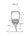
以下、一般的なウインター用ワイパーブレードを図7乃至図9を参照して説明する。この例は、自動車のフロントウインドガラス用のワイパー装置に使用されるウインター用ワイパーブレードについて説明する。
図において、1は払拭面としての自動車のフロントウインドガラス(以下、単にガラス面と称する)である。このガラス面1は、3次曲面をなす。
図において、2は前記ガラス面1を払拭するブレードラバーである。このブレードラバー2は、例えばゴム製からなり、ガラス面1を払拭する一端側(下端側)のほぼ逆三角形形状をなす払拭部20と、他端側(上端側)のほぼ台形形状をなす保持部21と、その保持部21の下面と前記払拭部20の上面との間に一体に設けた中間部の首部22とからなる。
【0003】
図において、3は前記ブレードラバー2を保持すると共に前記ブレードラバー2に弾性を付与するバーティブラ3である。このバーティブラ3は、内側の形状が前記ブレードラバー2の保持部21の外形状より一回り大きいロ形状をなし、その下面に前記ブレードラバー2の首部22の幅より若干大きい幅の切欠30を設けてなる。このバーティブラ3を前記ブレードラバー2の保持部21に遊嵌外嵌し、かつこのバーティブラ3の切欠30に前記ブレードラバー2の首部22を遊嵌挿通する。このようにして、ブレードラバー2をバーティブラ3で保持すると共に、バーティブラ3によりブレードラバー2がガラス面1に追従し得るための弾性をブレードラバー2に付与する。
【0004】
図において、4はプライマリーレバーである。このプライマリーレバー4は、例えば薄い鋼板を折り曲げて、上面板部と、左右両側面板部と、からなる。このプライマリーレバー4の中央の上面板部にクリップ機構40を固定する。このクリップ機構40は、前記プライマリーレバー4に前記ガラス面1とほぼ直交するリベット41により固定したクリッププレート(クリップベース)42と、そのクリッププレート42に前記ガラス面1とほぼ平行なリベット43により回動可能に取り付けたクリップ体44とからなる。
【0005】
図において、5はセカンダリーレバーである。このセカンダリーレバー5は、例えば薄い鋼板を折り曲げて、上面板部と、左右両側面板部と、からなる。このセカンダリーレバー5の外側の端部に係合爪50を設ける。この2本のセカンダリーレバー5のほぼ中央を前記プライマリーレバー4の両端に前記ガラス面1とほぼ平行なリベット51によりそれぞれ回動可能に取り付ける。
【0006】
図において、6はヨークである。このヨーク6は、例えば薄い鋼板を折り曲げて、上面板部と、左右両側面板部と、からなる。このヨーク6の両端部に係合爪60をそれぞれ設ける。この2本のヨーク6のほぼ中央を前記2本のセカンダリーレバー5の内側の端部に前記ガラス面1とほぼ平行なにリベット61によりそれぞれ回動可能に取り付ける。
【0007】
前記セカンダリーレバー5の係合爪50及び前記ヨーク6の係合爪60は、前記セカンダリーレバー5の左右両側面板部及び前記ヨーク6の左右両側面板部の下端をそれぞれ内側にほぼ直角に折り曲げてなる。この左右両側の係合爪50及び60の隙間52及び62を前記ブレードラバー2の首部22の幅より若干大きくする。このセカンダリーレバー5の係合爪50及びヨーク6の係合爪60を前記バーティブラ3に遊嵌外嵌し、かつこのセカンダリーレバー5の係合爪50の隙間52及びヨーク6の係合爪60の隙間62に前記ブレードラバー2の首部22を遊嵌挿通する。このようにして、前記セカンダリーレバー5の外側の端部の係合爪50及び前記ヨーク6の両端の係合爪60を、前記ブレードラバー2及び前記バーティブラ3に、それぞれ係合させる。
【0008】
このプライマリーレバー4及びセカンダリーレバー5及びヨーク6は、前記ブレードラバー2及び前記バーティブラ3を保持する保持レバー機構を構成する。この例の保持レバー機構は、2本のヨーク6の両端の係合爪60と2本のセカンダリーレバー5の外側端部の係合爪50との所謂6点支持機構であるが、その他に、2本のセカンダリーレバー5の両端の係合爪50の所謂4点支持機構、又は、4本のヨーク6の両端の係合爪60の所謂8点支持機構等がある。
【0009】
図において、7は例えば弾性部材(ゴム)製からなるカバーである。このカバー7は、前記ブレードラバー2の保持部21に外嵌するほぼロ形状をなしかつ下面部分の中央に切欠を有する外嵌部70と、その外嵌部70から延設して前記ブレードラバー2の首部22と前記バーティブラ3の切欠30及び前記セカンダリーレバー5の隙間52及び前記ヨーク6の隙間62との間に介装する巾狭部71と、その巾狭部71から前記プライマリーレバー4及び前記セカンダリーレバー5及び前記ヨーク6を外から覆う覆部72とからなる。
前記カバー7の外嵌部70を前記ブレードラバー2の保持部21に外嵌し、かつそのカバー7の巾狭部71を前記ブレードラバー2の首部22と前記バーティブラ3の切欠30及び前記セカンダリーレバー5の隙間52及び前記ヨーク6の隙間62との間に介装し、さらに前記カバーの覆部72で前記プライマリーレバー4及び前記セカンダリーレバー5及び前記ヨーク6を外から覆う。このカバー7の覆部72を前記プライマリーレバー4に覆ったところで、前記クリップ機構40を前記カバー7の覆部72を介して前記プライマリーレバー4にリベット41により固定する。
【0010】
なお、上述例においては、プライマリーレバー4もカバー7により覆われているが、このプライマリーレバー4をカバー7で覆わない場合もある。
そして、前記ブレードラバー2及びバーティブラ3及びプライマリーレバー4及びセカンダリーレバー5及びヨーク6及びカバー7は、ウインター用のワイパーブレードを構成する。
【0011】
図において、8はワイパー装置の駆動部である。この駆動部8は、ワイパーモータ(図示せず)の駆動軸に連結し、前記ガラス面1に対してほぼ直交する方向に延設したワイパー軸80と、そのワイパー軸80に取り付けたアームヘッド81と、そのアームヘッド81に前記ワイパー軸80に対してほぼ直交するヒンジピン82により回動可能に取り付けた前記ワイパーアーム83と、そのワイパーアーム83と前記アームヘッド81とに介装して前記ワイパーアーム83をガラス面1側に常時押圧する弾性部材(図示せず)と、を備えてなる。この駆動側のワイパーアーム83の先端を前記ワイパーブレードのプライマリーレバー4のクリップ機構40に着脱可能に取り付ける。
【0012】
かくして、駆動部8のワイパーモータを駆動させることにより、ワイパーブレードが、図8中の矢印D方向及び矢印E方向に、高速往復運動、低速往復運動、間欠往復運動、を行なって、ブレードラバー2の払拭部20でガラス面1上を払拭する。一方、前記カバー7は、前記ブレードラバー2の一部(保持部20及び首部21)及び前記バーティブラ3及び前記プライマリーレバー4及び前記セカンダリーレバー5及び前記ヨーク6を覆って、それらに雪や氷等が付着するのを防ぐことができる。このように、このウインター用ワイパーブレードは、寒冷地若しくは冬季におけるガラス面1を払拭するのに適しているものである。なお、上述のワイパー装置において、ワイパーブレードを収納したとき(ワイパー装置の駆動を停止させたとき)、ワイパーブレードは矢印E方向側が下向きとなる。
【0013】
そして、上述のウインター用ワイパーブレードにおいては、ブレードラバー2及びカバー7を保持すると共に、ブレードラバー2がガラス面1に追従し得るための弾性をブレードラバー2に付与するバーティブラ3の役目が重要である。
このバーティブラ3としては、上述の例のような合成樹脂から構成されたもの(実開平1−174272号公報に記載のもの)と、実開平4−67164号公報に記載のような金属板から構成されたものとがある。
【0014】
【発明が解決しようとする課題】
ところが、上述の従来のウインター用ワイパーブレードにおけるバーティブラの前者は、合成樹脂から構成されているので、長尺物のバーティブラの長手方向に対して直交する方向の弾性、すなわちブレードラバー2がガラス面1に追従し得るための弾性に問題が有る。
また、後者は、金属板から構成されているので、上述の弾性には問題が無いが、ブレードラバー2及びカバー7を保持するための係合爪を長尺物の金属板に折り曲げ加工により形成する必要が有るので、形状が複雑となり、打抜き加工及び折り曲げ加工等製造上の高いコストに問題が有る。
【0015】
本発明の目的は、ブレードラバーの払拭面への追従性が良く、しかもコストが安価なウインター用ワイパーブレードにおけるバーティブラを提供することにある。
【0016】
【課題を解決するための手段】
本発明は、上述の目的を達成するために、金属製の第1部材と樹脂製又は金属製の第2部材とからバーティブラが構成されており、
前記第1部材は、細長い板形状をなし、ブレードラバーが払拭面に追従し得るための弾性をブレードラバーに付与するものであり、
前記第2部材は、前記第1部材とは別体であり、前記第1部材にその第1部材の長手方向に任意複数個取り付けられ、前記ブレードラバー及びカバーを保持する保持部を有する、
ことを特徴とする。
【0017】
その結果、本発明のウインター用ワイパーブレードにおけるバーティブラは、金属製の第1部材により、ブレードラバーが払拭面に追従し得るための弾性がブレードラバーに付与されるので、従来の合成樹脂製のバーティブラと比較して、ブレードラバーの払拭面への追従性が良い。
また、ブレードラバーに弾性を付与する金属製の第1部材はただ単に細長い板形状をなすだけで形状が複雑ではない。一方、ブレードラバー及びカバーを保持する樹脂製又は金属製の第2部材は保持部を有するだけで、その形状は従来の金属製のバーティブラと比較して複雑ではない。この結果、バーティブラの製造コストを低減できる。
【0018】
【発明の実施の形態】
以下、本発明のウインター用ワイパーブレードにおけるバーティブラの実施の形態のうちの2例を図1乃至図6を参照して説明する。
図1乃至図4は本発明のウインター用ワイパーブレードにおけるバーティブラの第1の実施の形態を示す。
この例は、自動車のフロントウインドガラス用のワイパー装置に使用されるウインター用ワイパーブレードにおけるバーティブラについて説明する。図中、図7乃至図9と同符号は同一のものを示す。
【0019】
図1において、9は本発明のバーティブラである。この本発明のバーティブラ9は、金属製の第1部材91と樹脂製の第2部材92とから構成されている。
前記第1部材91は、前記第2部材92とは別体であり、細長い板形状をなし、ブレードラバー2がガラス面1に追従し得るための弾性をブレードラバー2に付与するものである。この第1部材91の一面(上面)には球形状の嵌合凸部910が1個若しくは複数個等間隔に一体に突設されている。なお、この第1部材91としては、通常の夏用のワイパーブレードのバーティブラ(例えば長手方向に溝が設けられているもの等)を使用しても良い。
【0020】
前記第2部材92は、前記第1部材92とは別体であり、断面日の字形状をなし、前記第1部材91が挿通する上挿通開口920と、ブレードラバー2及びカバー7が挿通保持される下挿通開口921とを有する。この第2部材92の上板の中央には円形の嵌合孔922が設けられている。この第2部材92の上板の長手方向側の両端面には突き当たり面923が設けられている。この両端の突き当たり面923間の長さが上述の複数この嵌合凸部910間の距離とほぼ等しい。また、この第2部材92の下板の中央にはブレードラバー2の首部22の幅より若干大きい幅の切欠924が設けられている。
【0021】
そして、第1部材91を第2部材92の上挿通開口920に挿通させ、その第1部材91の嵌合凸部910と第2部材92の嵌合孔922とを嵌合させて、任意複数個の第2部材92を第1部材91に固定的にセットすることにより、図1に示すような本発明のウインター用ワイパーブレードにおけるバーティブラ9が構成される。
【0022】
上述の複数個の第2部材92は、第1部材91の長手方向に全体に亘ってセットしても良いし、又は第1部材91の所定の箇所に部分的にセットしても良い。
また、この複数個の第2部材92は、隣同士の突き当たり面923を突き当てて直列に並べて使用する。
さらに、この複数個の第2部材92は、ウインター用ワイパーブレードの長さ及び第1部材91の長さの相違に対しては、セットする個数により調整できる。
【0023】
上述のように構成された本発明のウインター用ワイパーブレードにおけるバーティブラ9の下挿通開口921をブレードラバー2の保持部21に遊嵌外嵌し、かつこの本発明のバーティブラ9の切欠924にブレードラバー2の首部22を遊嵌挿通する。この結果、ブレードラバー2に弾性を付与すると共に、ブレードラバー2及びカバー7を保持することができる。上述の下挿通開口921(及び切欠924)がブレードラバー2及びカバー7を保持する保持部を構成する。
この本発明のバーティブラ9及びブレードラバー2及びカバー7をレバー機構(プライマリーレバー4及びセカンダリーレバー5及びヨーク6)により保持することにより、ウインター用ワイパーブレードが構成される。
【0024】
この実施の形態における本発明のウインター用ワイパーブレードにおけるバーティブラ9は、金属製の第1部材91により、ブレードラバー2がミラー面1に追従し得るための弾性がブレードラバー2に付与されるので、従来の合成樹脂製のバーティブラと比較して、ブレードラバー2のミラー面1への追従性が良い。
また、ブレードラバー2に弾性を付与する金属製の第1部材91はただ単に細長い板形状をなすだけで形状が複雑ではない。若しくは、形状が複雑でない通常の夏用のワイパーブレードのバーティブラを使用できる。一方、ブレードラバー2及びカバー7を保持する樹脂製の第2部材92は保持部を有する断面日の字形状をなすだけで、その形状は従来の金属製のバーティブラと比較して複雑ではない。この結果、バーティブラ9の製造コストを低減できる。
【0025】
図4は本発明のウインター用ワイパーブレードにおけるバーティブラの第1の実施の形態の変形例を示す。この変形例は、第1部材91に嵌合孔911を設け、第2部材92に嵌合凸部925を設けたものであり、上述のものと同様の作用効果を達成することができる。
【0026】
図5及び図6は本発明のウインター用ワイパーブレードにおけるバーティブラの第2の実施の形態を示す。
この例は、自動車のフロントウインドガラス用のワイパー装置について説明する。図中、図1乃至図4及び図7乃至図9と同符号は同一のものを示す。
【0027】
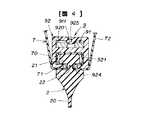
この実施の形態のものは、第2部材93を金属製から構成したものである。この金属製の第2部材93は、前記第1部材92とは別体であり、短尺物の金属板に打抜き加工及び折り曲げ加工等を施して構成されているものである。この第2部材93の上板の中央部を下方に折り曲げて、この上板の中央部と両端部との間の開口に第1部材91が挿通する上挿通開口930が形成されている。また、この第2部材93の左右両側板を折り曲げ、かつ左右両下板を折り曲げて、ブレードラバー2及びカバー7が挿通保持される下挿通開口931が形成されている。この第2部材93の上板の中央部には円形の嵌合孔932が設けられている。この第2部材93の上板の長手方向側の両端面には突き当たり面933が設けられている。この第2部材92の左右両下板の間にはブレードラバー2の首部22の幅より若干大きい幅の切欠934が設けられている。
そして、上述の第1の実施の形態と同様に、第1部材91に任意複数個の第2部材93をセットする。このとき、第1部材91の嵌合凸部910は下向きとなっている。
【0028】
この実施の形態における本発明のウインター用ワイパーブレードにおけるバーティブラは、上述の実施の形態のものと同様の作用効果を達成することができる。特に、この実施の形態の第2部材93は、金属製から構成されているが、短尺物の金属板に打抜き加工及び折り曲げ加工等を施して構成されているものであるから、長尺物の金属板に打抜き加工及び折り曲げ加工等を施して構成されている従来の金属製のバーティブラと比較して、形状が複雑ではない。この結果、製造コストが高くなる虞が無い。
【0029】
なお、上述の実施の形態においては、第2部材92、93が第1部材91に嵌合凸部910、925、と嵌合孔922、911、932との嵌合により固定的にセットされているが、第2部材92、93が第1部材91に対して若干スライドしても良い。
【0030】
また、上述の実施の形態においては、自動車のフロントウインドウガラスを払拭するウインター用ワイパーブレードにおけるバーティブラについて説明したが、本発明はその他のウインター用ワイパーブレードにおけるバーティブラにも適用することができる。
【0031】
【発明の効果】
以上から明らかなように、本発明のウインター用ワイパーブレードにおけるバーティブラは、ブレードラバーの払拭面への追従性が良く、しかもコストが安価である。
【図面の簡単な説明】
【図1】本発明のウインター用ワイパーブレードにおけるバーティブラの第1の実施の形態を示した一部の斜視図である。
【図2】同じく第1部材と第2部材との分解斜視図である。
【図3】図1におけるIII−III線断面図である。
【図4】嵌合凸部と嵌合孔との変形例を示した図3と対応する断面図である。
【図5】本発明のウインター用ワイパーブレードにおけるバーティブラの第2の実施の形態を示した第2部材の斜視図である。
【図6】図3及び図4に対応する図5におけるVI−VI線断面図である。
【図7】従来のバーティブラを使用しているウインター用ワイパーブレードであって、そのワイパーブレードからカバーを取り除いた状態の側面図である。
【図8】従来のバーティブラを使用しているウインター用ワイパーブレードであって、そのワイパーブレードにカバーを取り付けた状態の斜視図である。
【図9】図8におけるIX−IX線断面図である。
【符号の説明】
1…ガラス面(払拭面)、2…ブレードラバー、3…バーティブラ、4…プライマリーレバー、5…セカンダリーレバー、6…ヨーク、7…カバー、8…ワイパー駆動部、9…バーティブラ、91…第1部材、910…嵌合凸部、911…嵌合透孔、92、93…第2部材、920、930…上挿通開口、921、931…下挿通開口、922、932…嵌合孔、923、933…突き当たり面、924、934…切欠、925…嵌合凸部。[0001]
BACKGROUND OF THE INVENTION
The present invention relates to a wiper blade for a winter used in, for example, a cold district or winter, and particularly relates to a vertebra in a wiper blade for a winter that has good followability to the wiping surface of a blade rubber and is inexpensive.
[0002]
[Prior art]
Hereinafter, a typical winter wiper blade will be described with reference to FIGS. In this example, a windshield wiper blade used in a windscreen wiper device for an automobile is described.
In the figure,
In the figure,
[0003]
In the figure,
[0004]
In the figure, 4 is a primary lever. The primary lever 4 is composed of, for example, a thin steel plate and a top plate portion and left and right side plate portions. The
[0005]
In the figure, 5 is a secondary lever. The
[0006]
In the figure, 6 is a yoke. The
[0007]
The
[0008]
The primary lever 4, the
[0009]
In the figure, 7 is a cover made of, for example, an elastic member (rubber). The
The
[0010]
In the above example, the primary lever 4 is also covered with the
The
[0011]
In the figure, 8 is a drive unit of the wiper device. The
[0012]
Thus, by driving the wiper motor of the
[0013]
In the winter wiper blade described above, the role of the
The
[0014]
[Problems to be solved by the invention]
However, since the former of the above-mentioned conventional wiper blade for a winter wiper is made of synthetic resin, the elasticity in the direction orthogonal to the longitudinal direction of the long vertebra, that is, the
Further, since the latter is composed of a metal plate, there is no problem with the above-mentioned elasticity, but an engagement claw for holding the
[0015]
An object of the present invention is to provide a vertebra in a wiper blade for a winter that has good followability to a wiping surface of a blade rubber and is inexpensive.
[0016]
[Means for Solving the Problems]
In the present invention, in order to achieve the above-mentioned object, a vertebra is constituted by a first member made of metal and a second member made of resin or metal,
The first member has an elongated plate shape, and imparts elasticity to the blade rubber so that the blade rubber can follow the wiping surface.
The second member isseparate from the first member, and is attached to the first member in an arbitrary number in the longitudinal direction of the first member, and has a holding portion that holds the blade rubber and the cover.
It is characterized by that.
[0017]
As a result, the vertical wiper in the winter wiper blade according to the present invention is provided with elasticity so that the blade rubber can follow the wiping surface by the metal first member. Compared with, the followability to the wiping surface of the blade rubber is good.
In addition, the metal first member that imparts elasticity to the blade rubber simply has an elongated plate shape, and the shape is not complicated. On the other hand, the second member made of resin or metal that holds the blade rubber and the cover only has a holding portion, and the shape thereof is not complicated as compared with a conventional metal vertebra. As a result, the manufacturing cost of the vertebra can be reduced.
[0018]
DETAILED DESCRIPTION OF THE INVENTION
Hereinafter, two examples of the embodiment of the vertebra in the winter wiper blade of the present invention will be described with reference to FIGS.
1 to 4 show a first embodiment of a vertebra in a winter wiper blade of the present invention.
This example describes a vertebra in a winter wiper blade used in a windscreen wiper device for an automobile. In the figure, the same reference numerals as those in FIGS. 7 to 9 denote the same components.
[0019]
In FIG. 1, 9 is a vertebra of the present invention. The
The
[0020]
The
[0021]
Then, the
[0022]
The plurality of
The plurality of
Further, the plurality of
[0023]
In the winter wiper blade of the present invention configured as described above, the
The windshield wiper blade is configured by holding the
[0024]
In this embodiment, the
Further, the metal
[0025]
FIG. 4 shows a modification of the first embodiment of the vertebra in the winter wiper blade of the present invention. In this modification, the
[0026]
5 and 6 show a second embodiment of the vertebra in the winter wiper blade of the present invention.
This example describes a wiper device for a front windshield of an automobile. In the figure, the same reference numerals as those in FIGS. 1 to 4 and FIGS. 7 to 9 denote the same components.
[0027]
In this embodiment, the
Then, as in the first embodiment described above, an arbitrary plurality of
[0028]
The vertebra in the winter wiper blade of the present invention in this embodiment can achieve the same effects as those in the above-described embodiment. In particular, the
[0029]
In the above-described embodiment, the
[0030]
Further, in the above-described embodiment, the vertebra in the winter wiper blade for wiping the windshield glass of the automobile has been described. However, the present invention can also be applied to the vertebra in other winter wiper blades.
[0031]
【The invention's effect】
As is clear from the above, the vertebra in the winter wiper blade of the present invention has good followability to the wiping surface of the blade rubber and is inexpensive.
[Brief description of the drawings]
FIG. 1 is a partial perspective view showing a first embodiment of a vertebra in a winter wiper blade of the present invention.
FIG. 2 is an exploded perspective view of the first member and the second member.
FIG. 3 is a cross-sectional view taken along line III-III in FIG.
FIG. 4 is a cross-sectional view corresponding to FIG. 3 showing a modified example of the fitting convex portion and the fitting hole.
FIG. 5 is a perspective view of a second member showing a second embodiment of a vertebra in the winter wiper blade of the present invention.
6 is a cross-sectional view taken along line VI-VI in FIG. 5 corresponding to FIG. 3 and FIG. 4;
FIG. 7 is a side view of a winter wiper blade using a conventional vertebra, with a cover removed from the wiper blade.
FIG. 8 is a perspective view of a winter wiper blade using a conventional vertebra, with a cover attached to the wiper blade.
9 is a cross-sectional view taken along line IX-IX in FIG.
[Explanation of symbols]
DESCRIPTION OF
Claims (1)
Translated fromJapanese前記バーティブラは、金属製の第1部材と、第1部材とは別体である樹脂製又は金属製の第2部材とから構成されており、
前記第1部材は、細長い板形状をなし、前記ブレードラバーが前記払拭面に追従し得るための弾性を前記ブレードラバーに付与するものであり、
前記第2部材は、前記第1部材にその第1部材の長手方向に任意複数個取り付けられ、前記ブレードラバー及び前記カバーを保持する保持部を有する、
ことを特徴とするウインター用ワイパーブレードにおけるバーティブラ。A blade rubber for wiping the wiping surface; a vertebra for holding the blade rubber and imparting elasticity to the blade rubber; a holding lever mechanism for holding the blade rubber and the vertebra; the holding lever mechanism and the vertebra; In a wiper blade for winter comprising a cover that covers a part of the blade rubber,
The vertebra is composed of a metal first member anda resin or metal second member thatis a separate member from the first member ,
The first member has an elongated plate shape, and imparts elasticity to the blade rubber so that the blade rubber can follow the wiping surface;
The second member is attached to the first member in an arbitrary number in the longitudinal direction of the first member, and has a holding portion that holds the blade rubber and the cover.
A vertebra in a winter wiper blade.
Priority Applications (1)
| Application Number | Priority Date | Filing Date | Title |
|---|---|---|---|
| JP16298296AJP3653874B2 (en) | 1996-06-24 | 1996-06-24 | Vertibra in winter wiper blades |
Applications Claiming Priority (1)
| Application Number | Priority Date | Filing Date | Title |
|---|---|---|---|
| JP16298296AJP3653874B2 (en) | 1996-06-24 | 1996-06-24 | Vertibra in winter wiper blades |
Publications (2)
| Publication Number | Publication Date |
|---|---|
| JPH106932A JPH106932A (en) | 1998-01-13 |
| JP3653874B2true JP3653874B2 (en) | 2005-06-02 |
Family
ID=15764974
Family Applications (1)
| Application Number | Title | Priority Date | Filing Date |
|---|---|---|---|
| JP16298296AExpired - Fee RelatedJP3653874B2 (en) | 1996-06-24 | 1996-06-24 | Vertibra in winter wiper blades |
Country Status (1)
| Country | Link |
|---|---|
| JP (1) | JP3653874B2 (en) |
Families Citing this family (11)
| Publication number | Priority date | Publication date | Assignee | Title |
|---|---|---|---|---|
| DE10025710A1 (en)* | 2000-02-23 | 2001-08-30 | Bosch Gmbh Robert | Wiper blade for windows, in particular of motor vehicles |
| JP4672920B2 (en)* | 2001-07-25 | 2011-04-20 | 日本ワイパブレード株式会社 | Manufacturing method of backing for wiper blade and backing |
| WO2004012967A1 (en)* | 2002-07-31 | 2004-02-12 | Mitsuba Corporation | Wiper blade |
| WO2004054859A1 (en)* | 2002-12-17 | 2004-07-01 | Mitsuba Corporation | Wiper blade |
| WO2004054860A1 (en)* | 2002-12-17 | 2004-07-01 | Mitsuba Corporation | Wiper blade |
| WO2004078541A1 (en)* | 2003-03-07 | 2004-09-16 | Mitsuba Corporation | Wiper blade and method of producing the same |
| US7464433B2 (en)* | 2003-03-21 | 2008-12-16 | Robert Bosch Gmbh | Wiper blade to clean windows, in particular of motor vehicles |
| FR2879985A1 (en)* | 2004-12-23 | 2006-06-30 | Renault Sas | WIPER BLADE |
| CN101269652B (en)* | 2007-03-22 | 2010-07-28 | 黄世贤 | Automobile windshield wiper for both snow and rain |
| US7540061B1 (en)* | 2008-02-20 | 2009-06-02 | Shih-Hsien Huang | Array combinational type of windshield wiper |
| US7540062B1 (en)* | 2008-02-20 | 2009-06-02 | Shih-Hsien Huang | Structure for array combinational type of windshield wiper |
- 1996
- 1996-06-24JPJP16298296Apatent/JP3653874B2/ennot_activeExpired - Fee Related
Also Published As
| Publication number | Publication date |
|---|---|
| JPH106932A (en) | 1998-01-13 |
Similar Documents
| Publication | Publication Date | Title |
|---|---|---|
| EP1816041B1 (en) | Wiper blade | |
| EP1769987B1 (en) | Wiper blade | |
| KR101433098B1 (en) | Wiper blade | |
| EP1681216B1 (en) | Windshield wiper device | |
| US7373688B2 (en) | Wiper blade provided with detachable blade rubber and wiper system having the same | |
| US6820302B2 (en) | Wiper arm comprising a wiper blade which is connected to the same in an articulated manner | |
| US7254862B2 (en) | Wiper blade | |
| JP3653874B2 (en) | Vertibra in winter wiper blades | |
| EP1795406B1 (en) | A windscreen wiper device | |
| US20060090282A1 (en) | Wiper blade | |
| US8479349B2 (en) | Vehicle provided with at least two windscreen wiper devices | |
| JP4085914B2 (en) | Wiper device fitting and wiper device | |
| JP2950120B2 (en) | Wiper device | |
| JPH0715466U (en) | Wiper device | |
| JP2008238868A (en) | Wiper blade | |
| US20080184516A1 (en) | Windscreen Wiper Arm | |
| JPH0715465U (en) | Wiper device | |
| JP2545323Y2 (en) | Winter blades for vehicle wipers | |
| US11420596B2 (en) | Windscreen wiper device | |
| JP2006008025A (en) | Wiper blade | |
| JPH06263011A (en) | Wiper device | |
| KR20000012676U (en) | Automotive wiper support. | |
| JP2006062557A (en) | Wiper blade | |
| JP2006036131A (en) | Windshield wiper blade | |
| JP2008074314A (en) | Winter wiper blade |
Legal Events
| Date | Code | Title | Description |
|---|---|---|---|
| A977 | Report on retrieval | Free format text:JAPANESE INTERMEDIATE CODE: A971007 Effective date:20041015 | |
| A131 | Notification of reasons for refusal | Free format text:JAPANESE INTERMEDIATE CODE: A131 Effective date:20041109 | |
| A521 | Written amendment | Free format text:JAPANESE INTERMEDIATE CODE: A523 Effective date:20041215 | |
| TRDD | Decision of grant or rejection written | ||
| A01 | Written decision to grant a patent or to grant a registration (utility model) | Free format text:JAPANESE INTERMEDIATE CODE: A01 Effective date:20050208 | |
| A61 | First payment of annual fees (during grant procedure) | Free format text:JAPANESE INTERMEDIATE CODE: A61 Effective date:20050221 | |
| R150 | Certificate of patent or registration of utility model | Free format text:JAPANESE INTERMEDIATE CODE: R150 | |
| FPAY | Renewal fee payment (event date is renewal date of database) | Free format text:PAYMENT UNTIL: 20080311 Year of fee payment:3 | |
| FPAY | Renewal fee payment (event date is renewal date of database) | Free format text:PAYMENT UNTIL: 20090311 Year of fee payment:4 | |
| FPAY | Renewal fee payment (event date is renewal date of database) | Free format text:PAYMENT UNTIL: 20100311 Year of fee payment:5 | |
| FPAY | Renewal fee payment (event date is renewal date of database) | Free format text:PAYMENT UNTIL: 20100311 Year of fee payment:5 | |
| FPAY | Renewal fee payment (event date is renewal date of database) | Free format text:PAYMENT UNTIL: 20100311 Year of fee payment:5 | |
| FPAY | Renewal fee payment (event date is renewal date of database) | Free format text:PAYMENT UNTIL: 20110311 Year of fee payment:6 | |
| FPAY | Renewal fee payment (event date is renewal date of database) | Free format text:PAYMENT UNTIL: 20110311 Year of fee payment:6 | |
| FPAY | Renewal fee payment (event date is renewal date of database) | Free format text:PAYMENT UNTIL: 20120311 Year of fee payment:7 | |
| FPAY | Renewal fee payment (event date is renewal date of database) | Free format text:PAYMENT UNTIL: 20120311 Year of fee payment:7 | |
| FPAY | Renewal fee payment (event date is renewal date of database) | Free format text:PAYMENT UNTIL: 20120311 Year of fee payment:7 | |
| FPAY | Renewal fee payment (event date is renewal date of database) | Free format text:PAYMENT UNTIL: 20130311 Year of fee payment:8 | |
| FPAY | Renewal fee payment (event date is renewal date of database) | Free format text:PAYMENT UNTIL: 20130311 Year of fee payment:8 | |
| FPAY | Renewal fee payment (event date is renewal date of database) | Free format text:PAYMENT UNTIL: 20130311 Year of fee payment:8 | |
| FPAY | Renewal fee payment (event date is renewal date of database) | Free format text:PAYMENT UNTIL: 20140311 Year of fee payment:9 | |
| LAPS | Cancellation because of no payment of annual fees |