JP3653833B2 - Inkjet printer - Google Patents
Inkjet printerDownload PDFInfo
- Publication number
- JP3653833B2 JP3653833B2JP32407095AJP32407095AJP3653833B2JP 3653833 B2JP3653833 B2JP 3653833B2JP 32407095 AJP32407095 AJP 32407095AJP 32407095 AJP32407095 AJP 32407095AJP 3653833 B2JP3653833 B2JP 3653833B2
- Authority
- JP
- Japan
- Prior art keywords
- printing paper
- printing
- paper
- feeding
- conveying means
- Prior art date
- Legal status (The legal status is an assumption and is not a legal conclusion. Google has not performed a legal analysis and makes no representation as to the accuracy of the status listed.)
- Expired - Lifetime
Links
- 238000007599dischargingMethods0.000claimsdescription8
- 230000004308accommodationEffects0.000claimsdescription6
- 238000005192partitionMethods0.000description6
- 239000000428dustSubstances0.000description5
- 230000007246mechanismEffects0.000description5
- 239000000835fiberSubstances0.000description3
- 230000009191jumpingEffects0.000description3
- 230000000694effectsEffects0.000description2
- 238000005452bendingMethods0.000description1
- 238000011109contaminationMethods0.000description1
- 230000003247decreasing effectEffects0.000description1
- 238000010586diagramMethods0.000description1
- 238000002474experimental methodMethods0.000description1
- 239000000463materialSubstances0.000description1
- 238000000034methodMethods0.000description1
Images


Landscapes
- Ink Jet (AREA)
- Handling Of Cut Paper (AREA)
- Delivering By Means Of Belts And Rollers (AREA)
Description
Translated fromJapanese【0001】
【発明の属する技術分野】
本発明は、インクジェットヘッドのノズルから印刷用紙にインクを吐出して印刷を行うインクジェットプリンタであって、印刷用紙をその表面がインクジェットヘッドに接触して汚れないように排出することができるものに関する。
【0002】
【従来の技術】
従来、上記インクジェットプリンタとしては、図4に示すものが知られている。このものは、インクジェットヘッド51が、その印刷面(ノズル面)54とスタッカ72の上面78とが平行になる向きに設けられ、補助スタッカ72が印刷面54よりも下に配置されている。そして、給紙カセット14に装填された印刷用紙12は、給紙ローラ16によって搬送され、紙送りローラ31および押さえローラ32により挾まれて印刷ガイド35上に紙送りされる。続いて、印刷用紙12の所定の印刷位置まで紙送りされると紙送りローラ31が停止する。続いて、インクジェットヘッド51が搭載されたキャリッジ52が、図示しないキャリッジ駆動モータによってガイド軸53に沿って往復動され、インクジェットヘッド51は、そのノズルから印刷用紙12上にインクを吐出して印刷を行う。
【0003】
そして、所定幅の印刷が終了すると、紙送りローラが回転され、印刷用紙12が次の印刷位置まで紙送りされる。一方、印刷された印刷用紙12の前端122は、排紙ローラ60および拍車ローラ61によって挾まれて排出され、印刷が総て終了して印刷用紙12の後端121が、排出ローラ60および拍車ローラ61による挾持状態から解除されると、印刷用紙12は、補助スタッカ72の上面78に収容される。
【0004】
また、印字ヘッドが、その印字面と排出された印刷用紙を収容する面とが所定の角度をなすように設けられた印字装置が知られている(特開昭57−178779号公報)。このものは、ドライブローラ(紙送りローラ)およびフォロワローラ(押さえローラ)によって挾まれて搬送された印字用紙(印刷用紙)を平面プラテン(印刷ガイド)上に導き、印字ヘッドによって印字を行い、ドライブローラ(排出ローラ)およびフォロワローラ(押さえローラ)によって挾んで排出する構成である。
【0005】
【発明が解決しようとする課題】
上記従来の前者のものにより、印刷用紙が排出される状態を図5に示す。なお、分かり易くするために、インクジェットヘッド51と印刷ガイド35との間隔を実際よりも大きく描いてある。
図5に示すように、印刷用紙12は、排出ローラ60および拍車ローラ61によって排出されると、その自重によって矢印F1で示す力が作用して排出ローラ60と拍車ローラ61に挾まれた点を支点にして凸状に湾曲しようとする。
【0006】
そして、印刷用紙12が、紙送りローラ31と押さえローラ32とによる挾持状態を解かれると、印刷用紙12の有する用紙の形状を維持しようとする剛性力によって、印刷用紙12の送り出し方向後端121が跳ね上がり、その送り出し方向後端121がインクジェットヘッド51の印刷面54に接触する。
したがって、印刷用紙12の送り出し方向後端121が、インクジェットヘッド51の印刷面に付着したインクによって汚れるという問題がある。しかも、印刷用紙12の表面に付着した塵芥や紙の繊維などにより、インクジェットヘッド51のノズルが目詰まりするという問題もある。
【0007】
また、上記従来の後者のものは、その構成をインクジェットプリンタに適用したとすると、排出側のドライブローラと対になる押さえローラは、拍車ローラではなく、印刷用紙の印刷面との接触面積が大きいため、未乾燥状態の印刷用紙を挾んで排出するには適さない。しかも、スタッカを、印刷用紙の送り出し方向後端が、給紙側のドライブローラおよびフォロワローラから外れたときに、その印刷用紙の前端がスタッカの印刷用紙の収容面と当接する位置に設けるという構成もないため、印刷用紙の送り出し後端の印字ヘッド側への跳ね上がりを防止することもできない。
さらに、印字ヘッドよりも排出側のプラテンと対向する位置には、印刷用紙を案内するガイドが設けられているが、未乾燥の印刷面が接触するおそれがあるため不向きである。
したがって、上記のものは、インクジェットプリンタに適用することはできないという問題がある。
【0008】
そこで、本発明は、上述した諸課題を解決するためになされたものであり、その目的とするところは、印刷用紙の排出時に印刷用紙の送り出し方向後端が、インクジェットヘッドの印刷面と接触しないインクジェットプリンタを提供することにある。
【0009】
【課題を解決するための手段】
本発明は、上記目的を達成するため、請求項1に記載の発明では、印刷用紙を挾んで印字位置に送り出す給紙搬送手段と、この給紙搬送手段の印刷用紙の送り出し側に設けられており、その送り出された印刷用紙に上からインクを吐出して印刷を行うインクジェットヘッドと、このインクジェットヘッドによって印刷された印刷用紙の送り出し方向に設けられており、その印刷された印刷用紙を、下から当接する排出ローラおよび上から当接する拍車ローラにより挾んで排出する排出搬送手段と、前記給紙搬送手段と前記排出搬送手段との間で前記インクジェットヘッドと対向して設けられており、送られてきた印刷用紙を支持する印刷ガイドと、前記排出搬送手段から排出された印刷用紙を収容する収容手段と、が備えられたインクジェットプリンタにおいて、前記収容手段は、前記印刷用紙の送り出し方向後端が、前記給紙搬送手段から外れたときに、その印刷用紙の前端が前記収容手段の印刷用紙の収容面と当接し、前記印刷用紙の送り出し方向後端が前記印刷ガイド方向に付勢される位置に設けられ、前記排出搬送手段が前記印刷用紙を挾んだ状態で、前記印刷用紙の送り出し方向後端を前記印刷ガイドに、前記印刷用紙の前端を前記収容手段にそれぞれ当接させることで前記印刷用紙を前記インクジェットヘッドに向けてほぼ凹状に湾曲させるように、前記収容面が前記排出搬送手段による印刷用紙の排出方向と所定の角度に設定されているという技術的手段を採用する。
【0010】
請求項2に記載の発明では、請求項1に記載のインクジェットプリンタにおいて、前記収容面の上方には、前記排出搬送手段による排出方向から前記印刷用紙がその排出に伴い収容面上を移動しながら角度を変える範囲にわたって前記印刷用紙の上面と接触するものがないという技術的手段を採用する。
【0011】
請求項3に記載の発明では、請求項1または2に記載のインクジェットプリンタにおいて、前記収容手段は、前記印刷用紙がその排出に伴い収容面上を移動しながら角度を変える範囲よりも上方に、その収容手段の上方を覆う壁手段が設けられているという技術的手段を採用する。
【0012】
請求項4に記載の発明では、請求項1ないし3のいずれか1つに記載のインクジェットプリンタにおいて、前記所定の角度は、17°ないし60°であるという技術的手段を採用する。
【0013】
請求項5に記載の発明では、請求項1ないし3のいずれか1つに記載のインクジェットプリンタにおいて、前記所定の角度は、43°ないし47°であるという技術的手段を採用する。
【0014】
【作用】
請求項1ないし5に記載の発明では、上記収容手段は、上記印刷用紙の送り出し方向後端が、上記給紙搬送手段から外れたときに、その印刷用紙の前端が上記収容手段の印刷用紙の収容面と当接し、印刷用紙の送り出し方向後端が印刷ガイド方向に付勢される位置に設けられている。つまり、上記印刷用紙の送り出し方向後端が、上記給紙搬送手段から外れたときには、上記印刷用紙の前端が上記収容手段の印刷用紙の収容面と当接するため、上記印刷用紙が自重によって上記排出搬送手段を支点にして凸状に湾曲するのを防止することができる。
【0015】
しかも、排出搬送手段が印刷用紙を挾んだ状態で、印刷用紙の送り出し方向後端を印刷ガイドに、印刷用紙の前端を収容手段にそれぞれ当接させることで印刷用紙をインクジェットヘッドに向けてほぼ凹状に湾曲させるように、収容面が排出搬送手段による印刷用紙の排出方向と所定の角度に設定されているため、収容面に当接した後の印刷用紙は、排出方向に押される力によってインクジェットヘッドに向けてほぼ凹状の湾曲状態で排出されるので、印刷用紙をその送り出し方向後端をインクジェットヘッドと離れる方向に付勢しながら排出することができる。
したがって、上記印刷用紙の送り出し方向後端が、インクジェットヘッドの方向に跳ね上がって印刷面と接触してインクで汚れたり、インクジェットヘッドのノズルが目詰まりしたりすることを防止することができる。
【0016】
特に、請求項2に記載の発明では、上記収容面の上方には、上記排出搬送手段による排出方向から上記印刷用紙がその排出に伴い収容面上を移動しながら角度(凹状の湾曲の度合)を変える範囲にわたって上記印刷用紙の上面と接触するものがないため、上記印刷用紙の未乾燥の印刷面(上面)が擦れて汚れることを防止することができる。
【0017】
また、請求項3に記載の発明では、上記収容手段は、上記印刷用紙がその排出に伴い収容面上を移動しながら角度(凹状の湾曲の度合)を変える範囲よりも上方に、その収容手段の上方を覆う壁手段が設けられているため、その壁手段により、上記印刷用紙の未乾燥の印刷面(上面)が擦れて汚れることを防止することができるとともに、その印刷面に塵芥などが付着するのを防止することができる。
【0018】
さらに、請求項4に記載の発明では、上記収容面を、上記印刷用紙が上下に向けてほぼ凹状に湾曲されるように、上記排出搬送手段による印刷用紙の排出方向と17°ないし60°の角度に設定することにより、上記印刷用紙の送り出し方向後端の跳ね上がりを防止して、上記印刷用紙の送り出し方向後端が、インクジェットヘッドの印刷面と接触して汚れたり、インクジェットヘッドのノズルが目詰まりしたりすることを防止することができる。
【0019】
特に、請求項5に記載の発明では、上記角度を、43°ないし47°に設定することにより、より一層効果的に上記印刷用紙の送り出し方向後端が、インクジェットヘッドの印刷面と接触して汚れたり、インクジェットヘッドのノズルが目詰まりしたりすることを防止することができる。
【0020】
【発明の実施の形態】
以下、本発明の実施の一形態について図を参照して説明する。
図1は、本発明実施の形態に係るインクジェットプリンタ(以下、プリンタと略称する)の主な内部機構を示す縦断面説明図であり、図2は、図1に示すプリンタの紙送り、印刷、排紙および収容を行う部分の拡大説明図である。なお、図1および図2において、紙面左側がプリンタの後部であり、紙面右側がプリンタの前部である。
【0021】
図1に示すように、プリンタ10の後部には、印刷用紙12を複数枚収容できる給紙カセット14が設けられている。この給紙カセット14の下部前方であって、一番上の印刷用紙12と接する部分には、その印刷用紙12の幅方向に沿った回動軸を有する給紙ローラ16が設けられている。給紙カセット14内には、印刷用紙12を載置するトレイ18が設けられており、このトレイ18は、コイルばね20によって給紙ローラ16の方向に付勢されている。つまり、トレイ18上の印刷用紙12は、コイルばね20の付勢力によって給紙ローラ16の表面に接触され、モータ駆動により回転する給紙ローラ16によってガイド21上を下方に搬送される。
【0022】
カバーフレーム24内であって給紙ローラ16の斜め下部前方には、モータ駆動により回転する紙送りローラ31と、この紙送りローラ31の回転軸と平行の回転軸を有する押さえローラ32とからなる給紙搬送手段が備えられている。この押さえローラ32は、ローラホルダ33によって回転可能に軸支されており、このローラホルダ33は、取付軸34により回動可能に軸支されるとともに、図示しない付勢手段により、回動方向(図面時計方向)に付勢されている。つまり、その回動方向への付勢力により、押さえローラ32の表面が紙送りローラ31の表面に押圧される。
これにより、給紙ローラ16によってガイド21上を搬送された印刷用紙12は、紙送りローラ31と押さえローラ32との間に挾まれて斜め下部前方(印刷位置)に設けられた印刷ガイド35の上に紙送りされる。
【0023】
カバーフレーム24内には、印刷ガイド35の上面に対向する印刷面を有するインクジェットヘッド51を備えた印刷ユニット50が設けられている。印刷ガイド35は、後述する補助スタッカ72の収容面78に対してT°(=47°)の角度で設けられている。つまり、インクジェットヘッド51も、その印刷面54が、補助スタッカ72の収容面78に対して47°の角度となるように設けられている。インクジェットヘッド51の内部には、圧電素子が取付けられた複数のインク室が形成されており、その圧電素子に電圧を印加することにより、インク室の容積が変化され、インク室に形成されたノズルから印刷ガイド35上の印刷用紙12の上面にインクが吐出される。
【0024】
また、インクジェットヘッド51は、キャリッジ52の上に搭載されており、このキャリッジ52は、プリンタ内の幅方向に設けられたガイド軸53に取り付けられている。そして、キャリッジ52は、図示しないキャリッジ駆動モータによってガイド軸53に沿って往復動され、インクジェットヘッド51が印刷用紙12に対してその幅方向への印字を行う。
【0025】
インクジェットヘッド51の下方には、モータ駆動により回転する排出ローラ60と、この排出ローラ60との間で印刷された印刷用紙12を挾んで排出する拍車ローラ61とからなる排出搬送手段が設けられている。この拍車ローラ61は、外周に多数の尖った突起のある薄板材で作られている。つまり、印刷された印刷用紙12の上面は、インクが未乾燥の状態であり、インクジェット式でない他のプリンタのように接触面積の大きいゴムローラなどを用いることができないため、接触面積の小さい拍車ローラ61を用いる。
【0026】
また、上記拍車ローラ61は、板状の拍車ローラホルダ62に軸支されており、この拍車ローラホルダ62は、キャリッジ52を支持するフレーム63に取付けられている。このフレーム63の先端には、折曲げ部64が形成されており、この折曲げ部64と上記拍車ローラホルダ62とにより、ほぼ連続した面が形成されている。フレーム63の下方には、そのフレーム63とほぼ平行に仕切り板65が、カバーフレーム24の裏面から延びて形成されており、その仕切り板65の先端は、上記折曲げ部64の先端付近に位置している。
つまり、拍車ローラホルダ62、折曲げ部64および仕切り板65によってスタッカ70の後部上面を覆う壁が形成されているため、印刷された印刷用紙12の上面に塵芥などが落ちるのを防止することができる。
【0027】
給紙搬送手段31、32と排出搬送手段60、61とで形成する印刷用紙の通路は、用紙の搬送方向に向けて下り勾配に傾斜している。その角度は前記T°である。
排出搬送手段60、61の下方に段差をもって収容手段、すなわちスタッカ70が設けられている。スタッカ70は、拍車ローラホルダ62、折曲げ部64および仕切り板65の下方に位置するスタッカ基部71と、その前方へ延長した補助スタッカ72とから構成される。
スタッカ基部71は、ベースフレーム73の一部でもって印刷用紙12の排出方向にやや下り勾配に形成されている。補助スタッカ72は、スタッカ基部71の下に設けられており、ベースフレーム73の下に設けられたスタッカ収納空間74に対して出し入れ自在となっている。補助スタッカ72の前端には、排出された印刷用紙12の前端を当接させて前端を揃えて収容するための板状の当接部材75が形成されており、その裏面後端には、ストッパ76が設けられており、このストッパ76により、補助スタッカ72を引き出したときの外れ止めが行われる。
【0028】
また、補助スタッカ72は、図1に示すように、スタッカ収納空間74に収納された状態では、その当接部材75は、ベースフレーム73の前端に当接する位置(図1中にAで示す)にある。つまり、補助スタッカ72の全部をスタッカ収納空間74に収納することができる。なお、図中Bは、補助スタッカ72が前方に一杯に引き出された場合の当接部材75の位置を示す。また、このBに示す位置に引き出された状態において、スタッカ基部71の上面79(収容面)および補助スタッカ72の上面78を合わせた面(収容面)の全長L1は、使用可能な最大サイズの印刷用紙12の全長にほぼ等しくなる。
【0029】
なお、本実施の形態では、印刷用紙12の後端121が紙送りローラ31と押さえローラ32とによる挾持状態から解除されたときに、印刷用紙12の前端122がスタッカ基部71の上面79に既に当接しているようにするため、紙送りローラ31と押さえローラ32との接触点(印刷用紙12の挾持点)から、排出ローラ60と拍車ローラ61との接触点を通ってスタッカ70の上面78までの距離L5は、印刷用紙12の全長L4以下(L5≦L4)に設定されている。L5は、使用可能な最小サイズ、たとえばハガキの短辺100mmに決められている。また、補助スタッカ72は、印刷用紙12のフルスタック時に最上部の印刷用紙12が仕切り板65の先端に接触しない高さに設けられる。フルスタック時の印刷用紙の厚みD1は、本実施の形態では、約L4/10である。
【0030】
次に、上記構成のプリンタ10により、印刷用紙12の給紙から、印刷を経て排出されるまでの様子を説明する。
まず、給紙カセット14に収容された印刷用紙12は、反時計方向に回転する給紙ローラ16によってガイド21上に沿って紙送りローラ31側へ送られる。続いて、ガイド21上に沿って送られた印刷用紙12は、時計方向に回転する紙送りローラ31と、反時計方向に回転する押さえローラ32との間に挾まれて、印刷ガイド35上に沿って印刷面54側へ送られる。
【0031】
そして、印刷用紙12が印刷面54に達したときに紙送りローラ31の回転が停止し、インクジェットヘッド51が駆動され、インクジェットヘッド51は、印刷用紙12の上面にインクを吐出して印刷を行い、キャリッジ52の移動に伴って移動する。続いて、1行分の印刷が終了すると、紙送りローラ31が回転し、印刷用紙12は、次の印刷位置まで紙送りされ、上記同様の印刷が行われる。以後、同様の印刷と紙送りとが繰り返され、印刷用紙12は排出ローラ60と拍車ローラ61との間に挾まれて補助スタッカ72の方向へ排出される。
【0032】
ここで、印刷用紙12の後端121が、紙送りローラ31および押さえローラ32による挾持状態から解除されたときに、従来のように印刷用紙12の前端122が、まだスタッカ基部71の上面79に当接せず、宙吊りの状態であるとすると、印刷用紙12は、その自重によって下方へ垂れ下がって排出ローラ51を支点として凸状に湾曲し、その湾曲に伴って印刷用紙12の後端がインクジェットヘッド51の印刷面方向に跳ね上げられる。
しかし、本プリンタ10では、印刷用紙12の後端121が、紙送りローラ31と押さえローラ32とによる挾持状態から解除されたとき、つまり給紙手段から外れたときには、排出された印刷用紙12の前端122は、既にスタッカ基部71の上面79に47°の角度で当接されるため、図2のP1に示すように上方に向けて容易に凹状に湾曲することができる。
【0033】
その後、印刷用紙12は、紙送りが進むにつれて、収容面79、78上を移動しながら、図2のP2、P3で示すように次第に湾曲の度合い(角度)を緩め、当接部材75の方向に排出され、排出ローラ60および拍車ローラ61による挾持状態から解除され、スタッカ基部71の上面79および補助スタッカ72の上面78に収容される。
つまり、印刷用紙12の後端121は、紙送りローラ31および押さえローラ32による挾持を解除されても、印刷ガイド35の方向に付勢された状態に維持されるため、挾持の解除時に印刷面54の方向に跳ね上がることがない。
したがって、印刷用紙12の後端121が、印刷面54と接触してインクで汚れることを防止することができる。しかも、インクジェットヘッド51のノズルに塵芥や印刷用紙12の紙の繊維が付着してノズルの目詰まりを生じることもない。
また、印刷用紙12が上記のように角度を緩める過程において、拍車ローラホルダ62、折曲げ部64および仕切り板65は、その印刷用紙12よりも十分上方に離れているため、印刷用紙12の上面と接触するものがなく、印刷用紙12上の未乾燥のインクが擦られることが防止される。
【0034】
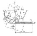
次に、上記発明の実施の形態では、インクジェットヘッド51の印刷面54と補助スタッカ72の上面78とのなす角度が47°に設定された場合について説明したが、図3に示すように、その角度をT°=17°に設定した場合であっても、上記47°に設定された場合と同じように、印刷用紙12の後端121の跳ね上がりを防止することができ、また、印刷用紙12上の未乾燥のインクが擦られることも防止することができる。
ただし、この場合は、印刷用紙12の後端121が給紙搬送手段から外れたときには、印刷用紙12の前端122が既にスタッカ基部71の上面79に当接しているようにするために、スタッカ70の設置位置を上記47°のものよりも、排出ローラ60に近い位置に設ける。つまり、上記補助スタッカ72の設置高さは、上記角度に応じて上記条件を満足するように設定変更する。
【0035】
なお、図4に示す従来のものの場合には、紙送りローラ31の中心から排出ローラ60の中心までの距離L2は、印刷用紙12を搬送するために必要な距離である。
しかし、上記各実施の形態に係るプリンタのように、インクジェットヘッド51を傾けて設置した場合には、その距離L3は、図1に示すように、L2cosT(T=47°または17°)となる。つまり、(L2−L2cosT)=L2(1−cosT)分短くなる。
したがって、その分、収容される印刷用紙12の後端121の位置をインクジェットヘッド寄りに設定することができるため、プリンタ10の専有面積を小さくすることができる。
【0036】
また、本発明者の実験によれば、上記角度を17°ないし60°の範囲に設定すれば、上記効果を奏することが明らかにされており、印刷用紙12のフルスタック量と、後端121の跳ね上がりとを比較考慮すると、上記角度を43°ないし47°の範囲に設定することが望ましいことが分かった。
なお、上記発明の実施の形態において、紙送りローラ31および押さえローラ32が本発明に係る給紙搬送手段に相当するが、押さえローラ32とインクジェットヘッド51との間に用紙ガイドを併設することもできる。この場合、印刷用紙12の後端がその用紙ガイドから外れたときをもって、給紙搬送手段から外れたものとする。また、排出ローラ60および拍車ローラ61が排出搬送手段に、スタッカ基部71および補助スタッカ72が収容手段に相当する。
【0037】
【発明の効果】
以上記述したように本発明によれば、印刷用紙の送り出し方向後端が、給紙搬送手段から外れたときにインクジェットヘッド方向へ跳ね上がるのを防止することができる。
したがって、印刷用紙の送り出し方向後端が、インクジェットヘッドと接触してインクで汚れることを防止することができる。しかも、インクジェットヘッドのノズルに塵芥や印刷用紙の紙の繊維が付着してノズルの目詰まりが生じることを防止することもできる。
【図面の簡単な説明】
【図1】 本発明実施の形態に係るプリンタの主な内部機構を示す縦断面説明図である。
【図2】 図1に示すプリンタの紙送りおよび排出の機構を拡大して示す縦断面部分説明図である。
【図3】 図2に示すプリンタのインクジェットヘッドの角度を17°に設定した場合の縦断面部分説明図である。
【図4】 従来のプリンタの主な内部機構を示す縦断面説明図である。
【図5】 図4に示すプリンタのプリンタ紙送りおよび排出の機構を拡大して示す説明図である。
【符号の説明】
10 プリンタ
12 印刷用紙
14 給紙カセット
16 給紙ローラ
31 紙送りローラ
32 押さえローラ
35 印刷ガイド
51 インクジェットヘッド
60 排出ローラ
61 拍車ローラ
72 補助スタッカ[0001]
BACKGROUND OF THE INVENTION
The present invention relates to an ink jet printer that performs printing by ejecting ink from a nozzle of an ink jet head onto a printing paper, and can discharge the printing paper so that the surface of the printing paper does not come into contact with the ink jet head.
[0002]
[Prior art]
Conventionally, the ink jet printer shown in FIG. 4 is known. In this apparatus, the
[0003]
When printing with a predetermined width is completed, the paper feed roller is rotated and the
[0004]
There is also known a printing apparatus in which a print head is provided such that its print surface and a surface for storing discharged print paper form a predetermined angle (Japanese Patent Laid-Open No. 57-17879). This drive guides the printing paper (printing paper) that is nipped and conveyed by the drive roller (paper feed roller) and follower roller (pressing roller) onto the flat platen (printing guide), and performs printing by the print head. It is configured to crawl and discharge by a roller (discharge roller) and a follower roller (pressing roller).
[0005]
[Problems to be solved by the invention]
FIG. 5 shows a state in which the printing paper is discharged by the above-mentioned conventional former. For easy understanding, the interval between the
As shown in FIG. 5, when the
[0006]
When the
Therefore, there is a problem that the
[0007]
Further, in the latter case of the prior art, if the configuration is applied to an ink jet printer, the pressing roller paired with the drive roller on the discharge side is not a spur roller but has a large contact area with the printing surface of the printing paper. Therefore, it is not suitable for picking up and discharging undried printing paper. In addition, the stacker is provided at a position where the front end of the print paper comes into contact with the print paper storage surface of the stacker when the rear end of the print paper in the feeding direction is removed from the drive roller and follower roller on the paper feed side. Therefore, it is not possible to prevent the trailing edge of the printing paper from feeding up toward the print head.
Further, a guide for guiding the printing paper is provided at a position facing the platen on the discharge side with respect to the print head, but it is not suitable because there is a possibility that an undried printing surface may come into contact.
Therefore, there is a problem that the above cannot be applied to an ink jet printer.
[0008]
Therefore, the present invention has been made to solve the above-described problems, and the object of the present invention is to prevent the rear end of the printing paper in the feeding direction from contacting the printing surface of the inkjet head when the printing paper is discharged. It is to provide an ink jet printer.
[0009]
[Means for Solving the Problems]
In order to achieve the above object, according to the present invention, in the invention described in claim 1, the sheet feeding / conveying means for picking up the printing paper and feeding it to the printing position is provided on the printing paper feeding side of the paper feeding / conveying means. An inkjet head that performs printing by ejecting ink from above onto the fed printing paper, and a feeding direction of the printing paper printed by the inkjet head. And a discharge conveying means for picking up and discharging by a discharge roller abutting from above and a spur roller abutting fromabove, and provided between the paper feed conveying means and the discharge conveying means so as to face theink jet head. the printing paper has a printing guide for supporting and housing means for housing the printing paper discharged fromsaid discharge conveying means, it is provided inkjet In the printer, the housing means, the dispensing direction trailing end of the printing paper, when deviated from said sheet feed conveying unit, the front end of the printing paper is brought into contact with the receiving surface of the printing paper of the housing means,said printing dispensing direction trailing end of the sheet is provided at a position thatwill be energized in the print guide direction,inthestatewherethedischarge conveying meanssandwiching the printingpaper, the feed direction rear end of the printing paper to the printing guide, Thestorage surface is set in a predetermined direction with respect to the discharge direction of the print paper by the discharge conveyance means so thatthe front end of the print paper is brought into contact with the storage means to bend theprint paper substantially in a concave shape toward theinkjet head. The technical means that the angle is set is adopted.
[0010]
According to a second aspect of the present invention, in the ink jet printer according to the first aspect, the printing paper moves on the storage surface as it is discharged from the discharge direction of the discharge conveyance unit above the storage surface. The technical means is adopted that there is nothing in contact with the upper surface of the printing paper over a range where the angle is changed.
[0011]
According to a third aspect of the present invention, in the ink jet printer according to the first or second aspect, the accommodating means is located above a range in which the printing paper changes its angle while moving on the accommodating surface as it is discharged. The technical means that the wall means which covers the upper part of the accommodating means is provided is employ | adopted.
[0012]
According to a fourth aspect of the present invention, in the ink jet printer according to any one of the first to third aspects, a technical means that the predetermined angle is 17 ° to 60 ° is employed.
[0013]
According to a fifth aspect of the present invention, in the ink jet printer according to any one of the first to third aspects, a technical means that the predetermined angle is 43 ° to 47 ° is employed.
[0014]
[Action]
In the invention according to any one of claims 1 to 5, when the rear end in the feeding direction of the printing paper is removed from the paper feeding / conveying means, the storage means is configured such that the front edge of the printing paper is the printing paper of the storage means. receiving surface abuts,dispensing direction trailing end of the printing paper is provided at a position thatwill be energized in the printing guide direction. That is, when the trailing edge of the printing paper feeding direction is separated from the paper feeding / conveying means, the front edge of the printing paper comes into contact with the printing paper containing surface of the containing means, so that the printing paper is discharged by its own weight. Using the conveying means as a fulcrum, it can be prevented from being curved in a convex shape.
[0015]
In addition, ina state where thedischarge conveyance unit holds the printing paper, the printing paper is almost directed toward theinkjet head by bringing the rear end of the printing paper in the feeding direction into contact with the printing guide and the front end of the printing paper in contact with the storage unit. Since thestorage surface is set at a predetermined angle with the discharge direction of the print paper by the discharge conveyance means so as to be curved in a concave shape, the print paper after coming into contact with thestorage surface isink jetted by a force pressed in the discharge direction.Since it is discharged toward thehead in a substantially concave curved state, it is possible to discharge the printing paper while urging the rear end in the feeding direction away from the inkjet head.
Therefore, it is possible to prevent the rear end of the printing paper from being fed out in the direction of the ink jet head and coming into contact with the printing surface to be contaminated with ink and the nozzles of the ink jet head are clogged.
[0016]
In particular, in the invention described in claim 2, an angle (degree of concave curvature) is formed above the storage surface while the printing paper moves on the storage surface as it is discharged from the discharge direction by the discharge conveyance unit. Since there is nothing in contact with the upper surface of the printing paper over the range where the change is made, it is possible to prevent the undried printing surface (upper surface) of the printing paper from being rubbed and soiled.
[0017]
According to a third aspect of the present invention, the accommodating means is located above the range in which the angle (the degree of concave curvature) changes while the printing paper moves on the accommodating surface as it is discharged. Since the wall means for covering the upper side of the printing paper is provided, the wall means can prevent the undried printing surface (upper surface) of the printing paper from being rubbed and soiled, and dust or the like can be found on the printing surface. Adhesion can be prevented.
[0018]
Furthermore, in the invention described in claim 4, the accommodation surface is arranged at 17 ° to 60 ° with respect to the discharge direction of the print paper by the discharge conveyance means so that the print paper is curved substantially concavely upward and downward. By setting the angle, the trailing edge of the printing paper in the feeding direction is prevented from jumping up, and the trailing edge of the printing paper in the feeding direction comes into contact with the printing surface of the inkjet head, or the nozzles of the inkjet head are not visible. It is possible to prevent clogging.
[0019]
In particular, in the invention described in claim 5, by setting the angle to 43 ° to 47 °, the rear end in the feeding direction of the printing paper is more effectively brought into contact with the printing surface of the inkjet head. It is possible to prevent contamination and clogging of the nozzles of the inkjet head.
[0020]
DETAILED DESCRIPTION OF THE INVENTION
Hereinafter, an embodiment of the present invention will be described with reference to the drawings.
FIG. 1 is a longitudinal sectional view illustrating main internal mechanisms of an ink jet printer (hereinafter abbreviated as a printer) according to an embodiment of the present invention, and FIG. 2 illustrates paper feeding, printing, and printing of the printer shown in FIG. FIG. 5 is an enlarged explanatory view of a portion that performs paper discharge and storage. 1 and 2, the left side of the paper is the rear part of the printer, and the right side of the paper is the front part of the printer.
[0021]
As shown in FIG. 1, a
[0022]
Inside the
As a result, the
[0023]
In the
[0024]
The
[0025]
Below the
[0026]
The
That is, the
[0027]
The path of the printing paper formed by the paper feeding / conveying
A storage means, that is, a
The
[0028]
Further, as shown in FIG. 1, the
[0029]
In this embodiment, when the
[0030]
Next, a state from the feeding of the
First, the
[0031]
Then, when the
[0032]
Here, when the
However, in the
[0033]
Thereafter, as the paper feed proceeds, the
That is, the
Therefore, it is possible to prevent the
Further, in the process in which the
[0034]
Next, in the embodiment of the present invention, the case where the angle formed between the
However, in this case, when the
[0035]
In the case of the conventional one shown in FIG. 4, the distance L2 from the center of the
However, when the
Accordingly, since the position of the
[0036]
Further, according to the experiment by the present inventor, it has been clarified that if the angle is set within a range of 17 ° to 60 °, the above-described effect can be obtained. It was found that it is desirable to set the angle in the range of 43 ° to 47 ° in consideration of the bounce of the lens.
In the embodiment of the present invention, the
[0037]
【The invention's effect】
As described above, according to the present invention, it is possible to prevent the trailing edge of the printing paper feed direction from jumping in the direction of the ink jet head when it is removed from the paper feeding / conveying means.
Therefore, it is possible to prevent the rear end of the printing paper in the feeding direction from coming into contact with the ink jet head and being stained with ink. In addition, it is possible to prevent clogging of the nozzles due to dust or paper fibers of the printing paper adhering to the nozzles of the inkjet head.
[Brief description of the drawings]
FIG. 1 is a longitudinal sectional view illustrating main internal mechanisms of a printer according to an embodiment of the present invention.
FIG. 2 is an enlarged partial cross-sectional explanatory view showing a paper feeding and discharging mechanism of the printer shown in FIG. 1;
FIG. 3 is a partial explanatory view of a longitudinal section when the angle of the inkjet head of the printer shown in FIG. 2 is set to 17 °.
FIG. 4 is a longitudinal sectional view illustrating main internal mechanisms of a conventional printer.
FIG. 5 is an explanatory diagram showing an enlarged view of a printer paper feed and discharge mechanism of the printer shown in FIG. 4;
[Explanation of symbols]
DESCRIPTION OF
Claims (5)
Translated fromJapaneseこの給紙搬送手段の印刷用紙の送り出し側に設けられており、その送り出された印刷用紙に上からインクを吐出して印刷を行うインクジェットヘッドと、
このインクジェットヘッドによって印刷された印刷用紙の送り出し方向に設けられており、その印刷された印刷用紙を、下から当接する排出ローラおよび上から当接する拍車ローラにより挾んで排出する排出搬送手段と、
前記給紙搬送手段と前記排出搬送手段との間で前記インクジェットヘッドと対向して設けられており、送られてきた印刷用紙を支持する印刷ガイドと、
前記排出搬送手段から排出された印刷用紙を収容する収容手段と、
が備えられたインクジェットプリンタにおいて、
前記収容手段は、前記印刷用紙の送り出し方向後端が、前記給紙搬送手段から外れたときに、その印刷用紙の前端が前記収容手段の印刷用紙の収容面と当接し、前記印刷用紙の送り出し方向後端が前記印刷ガイド方向に付勢される位置に設けられ、
前記排出搬送手段が前記印刷用紙を挾んだ状態で、前記印刷用紙の送り出し方向後端を前記印刷ガイドに、前記印刷用紙の前端を前記収容手段にそれぞれ当接させることで前記印刷用紙を前記インクジェットヘッドに向けてほぼ凹状に湾曲させるように、前記収容面が前記排出搬送手段による印刷用紙の排出方向と所定の角度に設定されていることを特徴とするインクジェットプリンタ。Paper feeding and conveying means for picking up printing paper and feeding it to the printing position;
An inkjet head that is provided on the feeding side of the printing paper of the paper feeding / conveying means, and that performs printing by ejecting ink from above onto the fed printing paper;
Discharging and conveying means provided in the feeding direction of the printing paper printed by the inkjet head, and the printed printing paper is held by a discharging roller that contacts from below and a spur roller that contacts from above and discharged and conveying means;
A printing guide provided between the paper feed conveying means and the discharge conveying means so as to face the ink jet head, and supporting a sent printing paper;
A housing means for housing the printing paper discharged fromsaid discharge conveying means,
In an inkjet printer equipped with
When the rear end of the printing paper in the feeding direction is disengaged from the paper feeding and conveying means, the front end of the printing paper comes into contact with the printing paper containing surface of the containing means, and the feeding meanssends out the printing paper. provided at aposition rearward end is Ruis biased to the printing guide direction,
Ina state in which thedischarge conveyance unit holds the printing paper, the printing paper ismovedto the printing guide by bringing the rear end in the feeding direction of the printing paper into contact with the printing guide, and the front end of the printing paper is brought into contact with the storage unit. An ink jet printer ,wherein the receivingsurface is set at a predetermined angle with respect to the discharge direction of the printing paper by the discharge and transport means so as to be bent substantially concavely toward theink jet head .
Priority Applications (1)
| Application Number | Priority Date | Filing Date | Title |
|---|---|---|---|
| JP32407095AJP3653833B2 (en) | 1995-11-18 | 1995-11-18 | Inkjet printer |
Applications Claiming Priority (1)
| Application Number | Priority Date | Filing Date | Title |
|---|---|---|---|
| JP32407095AJP3653833B2 (en) | 1995-11-18 | 1995-11-18 | Inkjet printer |
Publications (2)
| Publication Number | Publication Date |
|---|---|
| JPH09141842A JPH09141842A (en) | 1997-06-03 |
| JP3653833B2true JP3653833B2 (en) | 2005-06-02 |
Family
ID=18161819
Family Applications (1)
| Application Number | Title | Priority Date | Filing Date |
|---|---|---|---|
| JP32407095AExpired - LifetimeJP3653833B2 (en) | 1995-11-18 | 1995-11-18 | Inkjet printer |
Country Status (1)
| Country | Link |
|---|---|
| JP (1) | JP3653833B2 (en) |
Families Citing this family (1)
| Publication number | Priority date | Publication date | Assignee | Title |
|---|---|---|---|---|
| US7448734B2 (en)* | 2004-01-21 | 2008-11-11 | Silverbrook Research Pty Ltd | Inkjet printer cartridge with pagewidth printhead |
- 1995
- 1995-11-18JPJP32407095Apatent/JP3653833B2/ennot_activeExpired - Lifetime
Also Published As
| Publication number | Publication date |
|---|---|
| JPH09141842A (en) | 1997-06-03 |
Similar Documents
| Publication | Publication Date | Title |
|---|---|---|
| JP4120802B2 (en) | Recording device | |
| US20060244803A1 (en) | Ink-Jet Recording Apparatus | |
| JP2012030452A (en) | Inkjet printer | |
| JP3653833B2 (en) | Inkjet printer | |
| US20060152567A1 (en) | Feeding device and recording device | |
| US6074053A (en) | Printer with reduced ejected printed paper area | |
| JPH05124284A (en) | Ink jet printer | |
| JP2003326804A (en) | Recording device | |
| JPH0286475A (en) | liquid jet recording device | |
| JP2004322632A (en) | Recording medium floating prevention device, recording device, liquid ejecting device | |
| JP4666180B2 (en) | Recording device | |
| JPH10193590A (en) | Inkjet printer | |
| JP2004269124A (en) | Feeding device, recording device, and liquid ejecting device | |
| JP2948702B2 (en) | Sheet transport device | |
| JP2004106278A (en) | Printer | |
| JP3738819B2 (en) | Paper feeding device and recording device | |
| JP2003081468A (en) | Paper feeder and recording apparatus having the same | |
| JP2003112846A (en) | Recording device | |
| JP2002037501A (en) | Sheet material carrying device and image forming device | |
| JP4193049B2 (en) | Recording device | |
| JP2023095336A (en) | Sheet feeding device and recording device | |
| JP5591035B2 (en) | Recording device | |
| JP2001058738A (en) | Printing paper transport mechanism | |
| JPH08169616A (en) | Storing device for ink jut printer discharge recording sheet | |
| JP5876655B2 (en) | Recording device |
Legal Events
| Date | Code | Title | Description |
|---|---|---|---|
| A977 | Report on retrieval | Free format text:JAPANESE INTERMEDIATE CODE: A971007 Effective date:20040806 | |
| A131 | Notification of reasons for refusal | Free format text:JAPANESE INTERMEDIATE CODE: A131 Effective date:20041026 | |
| A521 | Written amendment | Free format text:JAPANESE INTERMEDIATE CODE: A523 Effective date:20041221 | |
| TRDD | Decision of grant or rejection written | ||
| A01 | Written decision to grant a patent or to grant a registration (utility model) | Free format text:JAPANESE INTERMEDIATE CODE: A01 Effective date:20050208 | |
| A61 | First payment of annual fees (during grant procedure) | Free format text:JAPANESE INTERMEDIATE CODE: A61 Effective date:20050221 | |
| R150 | Certificate of patent (=grant) or registration of utility model | Free format text:JAPANESE INTERMEDIATE CODE: R150 | |
| RD04 | Notification of resignation of power of attorney | Free format text:JAPANESE INTERMEDIATE CODE: A7424 Effective date:20051207 | |
| A072 | Dismissal of procedure | Free format text:JAPANESE INTERMEDIATE CODE: A072 Effective date:20060207 | |
| FPAY | Renewal fee payment (prs date is renewal date of database) | Free format text:PAYMENT UNTIL: 20080311 Year of fee payment:3 | |
| FPAY | Renewal fee payment (prs date is renewal date of database) | Free format text:PAYMENT UNTIL: 20090311 Year of fee payment:4 | |
| FPAY | Renewal fee payment (prs date is renewal date of database) | Free format text:PAYMENT UNTIL: 20090311 Year of fee payment:4 | |
| FPAY | Renewal fee payment (prs date is renewal date of database) | Free format text:PAYMENT UNTIL: 20110311 Year of fee payment:6 | |
| FPAY | Renewal fee payment (prs date is renewal date of database) | Free format text:PAYMENT UNTIL: 20120311 Year of fee payment:7 | |
| FPAY | Renewal fee payment (prs date is renewal date of database) | Free format text:PAYMENT UNTIL: 20120311 Year of fee payment:7 | |
| FPAY | Renewal fee payment (prs date is renewal date of database) | Free format text:PAYMENT UNTIL: 20130311 Year of fee payment:8 | |
| FPAY | Renewal fee payment (prs date is renewal date of database) | Free format text:PAYMENT UNTIL: 20130311 Year of fee payment:8 | |
| FPAY | Renewal fee payment (prs date is renewal date of database) | Free format text:PAYMENT UNTIL: 20140311 Year of fee payment:9 | |
| EXPY | Cancellation because of completion of term |