JP3652135B2 - Video signal recording / reproducing method, recording / reproducing apparatus, processing apparatus and recording medium having copy control information - Google Patents
Video signal recording / reproducing method, recording / reproducing apparatus, processing apparatus and recording medium having copy control informationDownload PDFInfo
- Publication number
- JP3652135B2 JP3652135B2JP24601698AJP24601698AJP3652135B2JP 3652135 B2JP3652135 B2JP 3652135B2JP 24601698 AJP24601698 AJP 24601698AJP 24601698 AJP24601698 AJP 24601698AJP 3652135 B2JP3652135 B2JP 3652135B2
- Authority
- JP
- Japan
- Prior art keywords
- signal
- video signal
- information
- cgms
- copy
- Prior art date
- Legal status (The legal status is an assumption and is not a legal conclusion. Google has not performed a legal analysis and makes no representation as to the accuracy of the status listed.)
- Expired - Fee Related
Links
Images


Classifications
- G—PHYSICS
- G06—COMPUTING OR CALCULATING; COUNTING
- G06T—IMAGE DATA PROCESSING OR GENERATION, IN GENERAL
- G06T1/00—General purpose image data processing
- G06T1/0021—Image watermarking
Landscapes
- Physics & Mathematics (AREA)
- General Physics & Mathematics (AREA)
- Engineering & Computer Science (AREA)
- Theoretical Computer Science (AREA)
- Television Signal Processing For Recording (AREA)
- Television Systems (AREA)
- Signal Processing For Digital Recording And Reproducing (AREA)
Description
Translated fromJapanese【0001】
【発明の属する技術分野】
本発明は、原画像の再生制御、又は記録制御、あるいはその画像の出所を明確にするために、画像データ、特に映像信号上に重畳、又は埋め込まれた別の情報、すなわち電子透かし情報及び世代管理信号を含むコピー制御情報を備えた映像信号の記録再生方法、記録再生装置及び処理装置並びに記録媒体に関するものである。
【0002】
【従来の技術】
映像信号に電子透かし(water mark、data hiding又はembedding)情報を埋め込むために幾つかの方法が提案されており、その代表的なものとしては映像情報メディア学会技術報告(ITE Technical Report Vol 21.No31.pp3〜8 データハイディング技術)に記載されている。また、従来の情報埋込み技術としては、日経エレクトロニクス(1997年)683号99頁から107頁に記載されている。これら従来技術においては、画像の統計的性質を利用して映像信号の一部に本来の映像信号が持っている情報とは異なる情報を映像信号の中に埋め込み、再生時にこの埋め込んだ情報を使って本来の画像の出所やさらに進んで再生の可否を決める制御信号を得ることが示されている。
この従来技術においては、画像の統計的性質を利用して画像の一部に本来の画像が持っている情報とは異なる情報を画像の中に埋め込み、再生時にこの埋め込んだ情報を使って本来の画像の出所やさらに進んで再生の可否を決める制御信号を発生することが示されている。
【0003】
【発明が解決しようとする課題】
一般に広く認められているコピー制御には、全面的なコピー禁止と一回のコピーのみ許容するものがある。後者は世代管理(CGMS:Copy Generation Management system)と位置づけられ、一回限りののコピーを許容する場合には、コピー動作時にこの信号は「一回コピー可」から「これ以上のコピーは不可」とする信号に書き換えられる。
しかしながら、上記の文献にはこのような技術と電子透かし情報とを組み合わせてコピー制御を行うことにについては記載されていない。
【0004】
本発明の目的は再生の可否を容易に行う事ができるコピー制御情報を備えた映像信号の記録再生方法、記録再生装置及び処理装置並びに記録媒体を提供する事にある。
本発明の他の目的は電子透かし情報及び世代管理信号等のコピー制御情報を備えた映像信号の記録再生方法、記録再生装置及び処理装置並びに記録媒体を提供することにある。
本発明のさらに他の目的は、コピー制御情報を不正操作した場合に再生信号の出力を禁止することが出来るコピー制御情報を備えた映像信号の再生方法、再生装置及び処理装置を提供することにある。
本発明のさらに他の目的は、VTRやビデオディスクなどでいったん記録された映像信号の輝度信号に含まれるコピー制御情報をもちいて世代管理を考慮したコピー制御を行うことが出来る映像信号の再生方法、再生装置及び処理装置を提供することにある。
【0005】
【発明を解決するための手段】
本発明の目的を達成するために、本発明による記録媒体は、映像信号と、前記映像信号に埋め込まれ、コピー制御情報を有する電子透かし情報と、前記映像信号に挿入されたコピー制御用のCGMS信号とが記録されている。この電子透かし情報は映像信号の予め定められた位置の輝度信号の輝度値を変更させることによって得られる。好ましくは、この輝度信号の輝度値の変更範囲は変更可能範囲に設定される。CGMS信号は映像信号のスキャン領域外に挿入される。好ましくは、このCGMS信号は水平同期信号近傍のスキャン領域外に挿入される。また、好ましくは、このCGMS信号は2ビット以上のビット数を有する信号である。この電子透かし情報はコピーフリー、一回コピー可能及びコピー禁止のいずれかの情報を持っている。また、このCGMS信号はコピーフリー、一回コピー可能及びコピー禁止のいずれかの情報を持っている。
【0006】
本発明による記録方法は、輝度信号の予め定められた位置の輝度値を変更して前記輝度信号にコピー制御情報を埋め込むことによって電子透かし情報を生成するステップと、コピー制御情報を有するCGMS信号を映像信号のスキャン領域外に挿入するステップとを備えている。
本発明よる記録方法は、映像信号に含まれる輝度信号の輝度値を変化させても視覚的に耐えられる範囲を計算するステップと、予め定められた位置の輝度信号の輝度値を前記算出された範囲内で変更させてコピー制御情報を有する電子透かし情報を生成するるステップと、コピー制御情報を有し、映像信号のスキャン領域外に挿入されるCGMS信号を生成するステップとを備えている。
また、本発明による記録方法は、映像信号にふくまれる輝度信号の輝度値を変化させても視覚的に耐えられる範囲を計算するステップと、予め定められた位置の輝度信号であって、変更される輝度値が前記算出された範囲内にある場合に、前記輝度値を変更させてコピー制御情報を有する電子透かし情報を生成するステップと、コピー制御情報を有し、映像信号のスキャン領域外に挿入されるCGMS信号を生成するステップとを備えている。
【0007】
本発明による再生方法は、輝度信号の輝度値を変更してコピー制御情報が埋め込まれた電子透かし情報と映像信号のスキャン領域外に挿入されたコピー制御情報を有するCGMS信号とを備えた映像信号から前記電子透かし情報とCGMS信号とを記録媒体から再生して、映像信号の出力を制御するために、前記電子透かし情報を検出するステップと、前記CGMS信号と検出するステップと、前記電子透かし情報からえられたコピー制御情報と前記CGMS信号から得られたコピー制御情報とから合理性に欠ける場合には映像信号の出力を遮断するステップとを備えている。この電子透かし信号及びCGMS信号はコピー禁止情報及び一回コピー可能情報のいずれか一方の情報を備えている。更に、この電子透かし情報から得られた一回コピー可能情報とCGMS信号から得られたコピー禁止情報によって映像信号を出力して表示するステップを備えている。また、電子透かし情報から得られたコピー禁止情報とCGMS信号から得られたコピー禁止情報によって映像信号を出力して表示するステップを備えている。CGMS信号が再生されない場合には映像信号の出力を遮断するステップを備えている。
【0008】
また、本発明の再生方法においては、ディスクの種類を判別するステップと、電子透かし情報からえられたコピー制御情報とCGMS信号から得られたコピー制御情報とディスクの種類情報から合理性に欠ける場合には映像信号の出力を遮断するステップとを備えている。ディスクが再生専用ディスクであり、電子透かし情報が一回のコピー可能の信号であり、かつ、CGMS信号が一回記録可能の信号である場合、前記映像信号を出力させるステップを備えている。ディスクが記録可能なディスクであり、電子透かし情報が一回のコピー可能の信号であり、かつ、CGMS信号が一回記録可能の信号である場合、前記映像信号の出力を遮断するステップを備えている。
【0009】
本発明の再生方法においては、輝度信号の輝度値を変更してコピー禁止及び一回のコピー可能のいずれかの情報が埋め込まれた電子透かし情報とコピー禁止及び一回のコピー可能のいずれかの情報を有するCGMS信号とを備えた映像信号から電子透かし情報とCGMS信号とを記録媒体から再生して、映像信号の記録を制御するために、前記電子透かし情報に埋め込まれたコピー制御情報を検出するステップと、前記CGMS信号からコピー制御情報を検出するステップと、これらコピー制御情報が合理的な関係にあるか否かを判断するステップと、合理的な関係にある時のみ前記映像信号の記録を許可するステップとを備えている。合理的な関係を判断するステップは電子透かし情報から得られた一回コピー可能情報とCGMS信号から得られた一回コピー可能情報をコピー禁止情報に書き換える状況から合理的であると判断する。また、電子透かし情報から得られた一回コピー可能情報をコピー禁止に、CGMS信号から得られた一回コピー可能情報をコピー禁止情報に書き換える状況から合理的であると判断する。
【0010】
本発明による記録装置は、映像信号に含まれる輝度信号の輝度値に応じて輝度値の変更範囲を計算する変更可能範囲算出回路と、予め定められた位置にある輝度信号の輝度値を算出された可変範囲内で変更してコピー制御情報を有する電子透かし情報を埋め込むための情報埋め込み処理回路と、コピー制御情報を有するCGMS信号を発生する発生回路と、CGMS信号を電子透かし情報が埋め込まれた輝度信号のスキャン領域範囲外に加算する加算回路とを備えている。
【0011】
また、本発明による記録装置は、映像信号に含まれる輝度信号の輝度値に応じて前記輝度値の変更範囲を計算する変更可能範囲算出回路と、予め定められた位置にある輝度信号の輝度値が算出された可変範囲内にある時に輝度信号の輝度値を変更してコピー制御情報を有する電子透かし情報を埋め込むための情報埋め込み処理回路と、コピー制御情報を有するCGMS信号を発生する発生回路と、CGMS信号を電子透かし情報が埋め込まれた輝度信号のスキャン領域範囲外に加算する加算回路とを備えている。
【0012】
本発明によるコピー制御情報を備えた映像信号の処理装置は、輝度信号の輝度値を変更してコピー制御情報が埋め込まれた電子透かし情報と映像信号のスキャン領域外に挿入されたコピー制御情報を有するCGMS信号とを備えた映像信号から前記電子透かし情報とCGMS信号とを記録媒体から再生して、映像信号の出力を制御するために、記録媒体から再生された映像信号を処理する回路と、電子透かし検出回路と、CGMS信号を検出するためのCGMS信号検出回路と、検出された電子透かし情報と検出されたCGMS信号とから映像信号処理回路を制御する出力制御回路とを備えている。出力制御回路は電子透かし情報からえられた一回コピー可能情報とCGMS信号から得られたコピー禁止情報によって、映像信号を出力させるように前記映像信号処理回路を制御する。また、出力制御回路は電子透かし情報からえられたコピー禁止情報とCGMS信号から得られたコピー禁止情報によって、映像信号を出力させるように映像信号処理回路を制御する。出力制御回路はCGMS信号が検出されない時には映像信号を出力させないように前記映像信号処理回路を制御する。記録媒体が記録可能な媒体である場合、出力制御回路は電子透かし情報からえられた一回コピー可能情報とCGMS信号から得られた一回コピー可能情報によって、映像信号を出力させないように映像信号処理回路を制御する。また、記録媒体が再生専用の媒体である場合、出力制御回路は電子透かし情報からえられた一回コピー可能情報とCGMS信号から得られた一回コピー可能情報によって、映像信号を出力させるように映像信号処理回路を制御する。この処理装置はディスクの種類を判別する回路とを備えている。ディスク種類判別回路の出力が記録可能なディスクを示す信号である場合、出力制御回路は電子透かし情報からえられた一回コピー可能情報とCGMS信号から得られた一回コピー可能情報によって、映像信号を出力させないように前記映像信号処理回路を制御する。また、ディスク種類判別回路の出力が再生専用ディスクを示す信号である場合、出力制御回路は電子透かし情報からえられた一回コピー可能情報とCGMS信号から得られた一回コピー可能情報によって、映像信号を出力させるように前記映像信号処理回路を制御する。
【0013】
本発明による処理装置は、CGMS信号の世代を更新する回路と、映像信号の出力を制御する書き換え及び制御回路とを備え、電子透かし信号とCGMS信号によって映像信号の出力可否を制御している。この書き換え及び制御回路は電子透かし情報から得られた一回コピー可能情報とCGMS信号から得られた一回コピー可能情報とによって、書き換え及び制御回路から映像信号を出力し、CGMS信号の一回記録可能情報をコピー禁止情報に書き換えている。書き換え及び制御回路は電子透かし情報から得られた一回コピー可能情報とCGMS信号から得られた一回コピー可能情報とによって、書き換え及び制御回路から映像信号を出力し、電子透かし情報から得られた一回コピー可能情報をコピー禁止に、CGMS信号の一回記録可能情報をコピー禁止情報に書き換えている。
【0014】
本発明による記録再生装置は、コピー制御用のビットとこのビットによって生成された制御信号が埋め込まれた電子透かし情報とから構成されるコピー制御情報が設けられた映像信号を記録し、映像信号を再生する時に直接検出されたビットと、電子透かし情報を検出した信号とを比較して、所定の関係にある時のみ映像信号を出力する。電子透かし情報を検出し、直接検出されたビットによる信号が一世代コピー可能を示した時のみビット生成手段による信号を変更すし、変更された信号、入力された電子透かし記録信号及び映像信号を同時に記録し、それ以降の記録を不可能な動作とする。ビットは一世代コピー可能を示した時のみこれ以上の記録を不可とする信号に書き換えられて、電子透かし記録信号及び映像信号と同時に記録される。
【0015】
本発明による再生装置は、電子透かし情報が記録された映像信号と、コピー制御用のビットが書き込まれたディスクから映像信号を再生するために、電子透かし情報検出手段と、ビット生成手段によって記録された信号を検出する手段と、ディスクを判別するためのディスク判別手段と、ディスク判別手段によって、ディスクが再生専用であり、電子透かし情報とビット情報が一致する場合にディスクに書き込まれた映像信号を再生する。また、ディスク判別手段によって、ディスクが記録再生可能であり、電子透かし情報とビット情報が一致した場合及び検出されたビット情報段による信号の一世代コピー可能が正しく変更されている場合に映像信号を再生する。ディスクが記録再生可能な場合には、電子透かし情報が一世代コピー可能情報であり、ビット生成手段の情報がこれ以上のコピーを禁止する情報の時にのみ映像信号が再生される。
【0016】
【発明の実施の形態】
以下、本発明によるコピー制御情報を備えた映像信号の記録再生方法、記録再生装置及び処理装置並びに記録媒体の実施の形態について、実施例を用い、図面を参照して説明する。
【0017】
まず、本発明による電子透かし情報の記録装置の一実施例について説明する。図1は本発明による電子透かし情報の記録装置の一実施例を示すブロック図であり、この実施例では、画素の輝度を変更して電子透かし情報を埋め込んでいる。
図1において、入力回路1に映像信号が入力される。この入力回路1から輝度信号が取り出され、変更可能範囲算出回路3に供給され、この輝度信号に基づいて、輝度信号を変更しても視覚的にあまり影響のない範囲を計算する。輝度変化の大きい部分では輝度信号を大きく変化させても視覚的にはあまり変化しないが、輝度変化の少ない部分では輝度の変化量も小さくしないと視覚的に目立つので、この変更可能範囲算出回路3ではこれを考慮して変更可能範囲を計算する。この変更可能範囲算出回路3は計算機のCPUで実現できる。この変更可能範囲算出回路3からの計算結果は情報埋込み処理回路5に供給され変更可能範囲内にある場合には映像信号の輝度を変えて電子透かし情報を輝度信号に埋め込む処理を行う。輝度信号を加工して電子透かし情報が埋め込まれた映像信号は一画面分の処理が終わるまで情報埋め込み処理回路5のメモリに記憶された後出力される。また、この回路において、変更可能範囲算出回路3での算出処理は以下のようにして処理される。
【0018】
(1)画像のエッジの変化が大きい所ではエッジ信号の振幅を大きく変化させても視覚的にはあまり変わらない。逆に、画像のエッジの変化が少ない所ではエッジ信号の振幅を大きく変えると視覚的に画像は大きく変化する。
(2)画像の変更範囲は、画像が視覚的に変化しない範囲、又は画像が視覚的に変化したとしても視聴の妨げにはならない範囲にとどめる。
このようにして電子透かし情報を埋め込むと、原画像と輝度は異なるが、視覚的には変わらない画像が得られる。また、変更可能範囲算出回路3は、各画素毎に、画像処理適用前の輝度と適用後の輝度を記憶し、これが変更可能範囲にあるか否かを確認し、変更可能範囲に入る場合にのみ輝度信号の変更を行う。
情報埋込み処理回路5は、まず、画像を構成する画素のうち輝度を変更する画素を選択する。次に、選択された各画素の内、輝度が変更可能範囲内にある画素について、輝度を特定値に変更することによって情報を埋め込む。その結果、電子透かし情報が埋め込まれた映像信号が得られる。
7は世代管理信号発生回路であり、2ビットの世代管理信号またはCGMS(Copy Generation Management System)信号を発生する。この世代管理信号は加算回路9で情報埋め込み処理回路5から出力された電子透かし情報が埋め込まれた映像信号と色信号回路11から出力された色度信号と加算され、出力回路12を通して記録媒体(図示せず)に記録される。
【0019】
次に、図2を用いて、情報埋込み処理回路5における輝度の変更方法について説明する。
図2は画素の輝度値を直線表示した模式図である。図において、一つの画素の輝度の値は0〜255まであるとする。本実施例では、この直線上の白い円の値は16の倍数に相当する輝度であり、埋込み情報“0”に対応する。黒い点の値は(16の倍数+8)の値に相当する点であり、埋込み情報“1”に対応するものとする。
最初に、情報埋込み処理回路5の基本動作に付いて説明する。電子透かし情報を得るには画像の画素に対応する輝度を、最近傍の白または黒の円に変更する必要がある。すなわち、その画素に埋め込みたい情報が“0”の場合には白円に変更し、“1”の場合には黒円に変更する。例えば、画素の輝度が図中の△の値、すなわち30の場合で、埋め込みたい情報が“0”の場合には、その画素の輝度を32に変更し、埋め込みたい情報が“1”の場合には、その輝度を24に変更する。
次に、変更可能範囲算出回路3の利用について説明する。電子透かし情報を埋め込む場合、画素の輝度の変更が大きすぎて画像が視覚的に変化する場合がある。これを防止するために、画素の値を変更できる範囲を変更可能範囲内とする必要がある。例えば、図2において、画素の輝度△の値が30で、その画素の輝度の変更可能範囲が26〜33であるとする。この場合、埋め込みたい情報が“0”の場合には、上記の基本動作通りに、その画素の輝度を32に変更しても差し支えない。しかし、埋め込みたい情報が“1”の場合には、変更先の輝度24が変更可能範囲に含まれていないので、この場合には24に最も近い値26に変更する。又は、この画素の輝度を変化させることをあきらめて、予め定められた他の画素の輝度を変更する。
【0020】
さらに、透かし挿入画像、すなわち電子透かし情報が埋め込まれた映像信号から電子透かし情報を抽出する方法について説明する。最初に、画素の輝度値が変更された画素を選択する。輝度が変更される画素の位置は予め定められているので、水平同期信号に基づいて得られたパルスによって選択することができる。すなわち、情報埋込み処理回路5における画素選択と同じ規則に従って輝度が変更された画素を選択する。
次に、選択された各画素について、その輝度信号を取り出し、その値が、16の倍数か(16の倍数+8)のいずれに近いかで、埋め込まれた情報が“0”か“1”かを判定する。
上述のように、情報埋込み処理回路65は変更可能な範囲内で輝度を変更しているので、輝度を16の倍数または(16の倍数+8)に正確に変更できない場合がある。そのため、情報の抽出において、誤りが生じる。しかしながら、この問題は同じ情報を複数の画素に重複して埋め込み、抽出において多数決を行うことによって解決できる。
【0021】
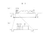
次に、図3(a)、図3(b)をもちいて、世代管理信号の一実施例について説明する。
図3(a)は世代管理信号が挿入された垂直期間のテレビジョン信号の概略の一実施例を示す模式図である。図3(b)は図3(a)の一部拡大図である。
図3(a)において、世代管理信号(CGMS信号と略称する。)31、35は例えば、垂直同期信号32の第17番目、18番目の水平同期期間の画面上部のスキャン範囲外の期間に挿入されている。従って、このCGMS信号31、35は通常画面には現れない。なお、33は映像信号である。
【0022】
図3(b)において、CGMS信号31は31a、31bからなる2ビットの信号である。この図において、34は映像信号が配置されているエリアである。図3(a)、図3(b)に示すテレビジョン信号は光ディスクまたはビデオテープなどの記録媒体に記録される。
【0023】
CGMS信号は三つのモード、すなわち、(1)コピーフリー、(2)一回コピー可能、(3)これ以上のコピー禁止モードを表す必要がある。
また、(2)一回コピー可能の場合にはコピー時にこの信号を(3)これ以上のコピー禁止と書き換える事が必要になる。これを世代更新という。
また(3)これ以上のコピー禁止モードでコピーした場合にはコピー動作は禁止されなければならない。そのために、図3(a)、図3(b)に示すCGMS信号31,35は2ビットの制御信号から構成されている。テレビジョン信号をコピーするための記録装置又は再生装置に設けられている電子透かし及びCGMS信号の処理装置でこのCGMS信号をみて再生可能か判断する。
世代更新とはCGMS信号を例えば、一回コピー可能のビット”10”をこれ以上コピー禁止ビット”11”に書き換える事を意味する。
以上述べた電子透かし情報は原画像の再生または記録制御情報、更にはその画像の出所を明確にする情報が含まれており、CGMS信号にはコピーフリー、一回コピー可能、これ以上のコピー禁止などの情報が含まれているが、以下の説明においてはこれら両方の情報を含めて、コピー制御情報という。
通常CGMS信号あるいは電子透かし情報のどちらか一方の制御信号を使用してコピー制御を行えば十分であると考えがちであるが、この制御信号の片方、例えば、CGMS信号のみを採用する場合には、この信号は容易に書き換えられるため、希望したコピー制御とは異なる制御を行う場合がある。世代更新をしなければならない状況、例えば一回コピーしたにも関わらず、CGMS信号の世代更新を行なわない場合、一回コピー可能のまま何度でもコピーが可能になってしまう。
【0024】
電子透かし情報は映像信号に含まれる輝度信号の輝度を変えているため、この電子透かし情報を世代更新することは困難である。例えば電子透かし情報が一回コピー可能を現している場合、この信号の世代更新は困難であるため、何回でもコピーが可能になってしまう。この場合このCGMS信号の世代更新をすることによって、再度のコピーを禁止することができる。
電子透かし情報を更新する回路が再生装置又はコピーをするための記録装置に採用されている場合には、電子透かし情報を世代更新することができる。この場合にはより明確にコピー禁止、又は再生禁止をすることが出来る。
CGMS信号を更新すべき状況にも拘わらず、このCGMS信号の世代更新を怠った場合には、電子透かし情報とCGMS信号の内容が同じになるため、これを検出して再度のコピー禁止または再生禁止を行うことができる。
このような場合を考えて、電子透かし情報とCGMS信号を使用してのコピー制御が考えられた。
【0025】
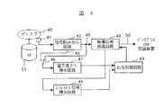
以下、電子透かし情報とCGMS信号を用いたコピー制御について、図4に示す本発明によるコピー制御情報処理装置をもちいて説明する。
図4は本発明によるコピー制御情報を備えた映像信号の処理装置の一実施例を示すブロック図である。
図4において、ディスク40は記録可能なディスク、例えばRAMディスク又は再生専用ディスク、例えばROMディスクである。記録可能なディスクの場合、このディスク40には、ディジタル放送信号が記録されている。このディジタル放送信号には一回コピー可能とする電子透かし情報と一回コピー可能とするCGMS信号が記録されていると仮定する。再生専用ディスクの場合にはコピー禁止の電子透かし情報とコピー禁止のCGMS信号が記録されている。ディスク40に記録された映像信号は光ピックアップ41で取り出され、信号読み出し回路42で読み出され、映像信号処理回路43で読み出された信号から映像信号を出力している。
【0026】
一般に、ディスク40から読み出された信号はMPEG処理が施されているが、このMPEG処理された信号は信号読み出し回路42でMPEG処理が解除されて伸張される。すなわち、信号読み出し回路42の出力端子44にはMPEG処理が施された信号が出力され、端子45からはMPEG処理が解除された信号が出力される。端子44または端子45に取り出された信号はスイッチ46によって選択されて電子透かし検出回路47に供給され、この回路47で電子透かし情報が検出される。なお、図4の回路において、スイッチ46を設けたのは、MPEG処理が施された信号を電子透かし回路47に入力しても良いし、MPEG処理がデコードされた信号を用いても良いことを示すためのものであり、通常電子透かし回路47は端子44又は端子45のいずれか一方の端子に接続される。
【0027】
CGMS信号検出回路48には映像信号処理回路43から映像信号が供給され、この回路48で、映像信号内に記憶されているCGMS信号31a、31b、又は35が検出される。
このようにして検出された電子透かし信号及びCGMS信号は出力制御回路49に入力され、この回路49で二つの信号が比較され、その合理性がチェックされる。なお、映像信号処理回路43の出力端子50には、画像を再生するためのディスプレイ(図示せず)、又は端子50から取り出された映像信号を記録するための記録装置(図示せず)が接続される。また、51は、ディスク40を回転させるためのモータである。
【0028】
以下にそのチェック内容について説明する。
ディスク40が再生専用ディスクの場合、一般的にその記録内容のコピーは許されていないのが通常である。従って再生専用ディスクの電子透かし情報はコピー不可となっている。よって、このような場合は電子透かし情報によって出力制御回路49はコピーが禁止されるように制御される。
ディスク40が再生専用ディスクで一回のコピーか許可されている場合には、出力端子50から記録装置(図示せず)に記録されながらCGMS信号は世代更新される。これについては図7に示す別の実施例を用いて説明する。
記録可能なディスク、例えばRAMディスクの場合には、ディジタル放送などを一次記録した記録媒体から再度コピーすることが考えられる。この場合、一般のディジタル放送信号には一回だけのコピーを許容するCGMS信号と電子透かし情報が挿入されており、一次記録のときに、CGMS信号は世代更新され、コピー禁止になっているはずである。
【0029】
端子50をディスプレイに接続して、この記録可能なディスクから映像信号を再生する場合、再生信号、又はCGMS信号に作為的な改竄が施された時には再生を禁止することが望まれている。
再生装置側の電子透かし検出回路47からは一回限りのコピー許可する電子透かし情報が検出され、CGMS信号検出回路48からは世代更新されたCGMS信号、すなわちコピー禁止するように更新されたCGMS信号が検出されるはずである。
この場合、一回コピーを許可する内容の電子透かし情報とコピーを禁止する内容のCGMS信号とが出力制御回路49に入力されるため、この電子透かし情報とCGMS信号とが合理的な関係にあると認識して再生を許可する信号を映像信号処理回路43に供給する。しかし、記録可能なディスクで記録した場合、電子透かし情報は原画像信号の一回限りのコピー許可を示す信号であっても良いが、CGMS信号は世代更新されていなけばならない。それにも拘わらず、一回コピーを許可するままであれば、これは記録時にCGMS信号を正しく更新しないままコピーを行ったと推察される。
従って、このような場合、出力制御回路49は正常に更新動作がされていないと判断してその出力を遮断する。
【0030】
電子透かし検出回路47で電子透かし情報が検出されたにも拘わらず、CGMS信号検出回路48からCGMS信号が検出されない場合には、何らかの不正な操作があったとして、出力制御回路49からは再生を禁止する信号が映像信号処理回路43に供給され、映像信号の再生が禁止される。
仮に、何らかの手段によって、電子透かし情報がコピー禁止となっており、且つCGMS信号もコピー禁止となっている放送信号を記録可能なディスクに記録した場合には、出力制御回路49には電子透かし情報及びCGMS信号の両方がコピー禁止の信号が供給されるので、この回路49からは再生を禁止する信号が映像信号処理回路43に供給され、再生は禁止される。
なお、電子透かし信号及びCGMS信号が共に検出されない場合にはコピーが禁止されていないため、出力制御端子からは再生を許可する信号が出力される。
【0031】
ディスク40の映像信号が再生許可された場合、この信号を記録装置に接続して記録することが考えられる。コピーフリーの場合には当然記録が可能であるが、そうでない場合には、CGMS信号がコピー禁止となっているために、これを検出してコピーは阻止される。例えば、CGMS信号の振幅を最大にしておけばこの信号によって、AGC制御回路(図示せず)が増幅器の利得が最低になるように制御され、信号が出力されないため、結果的にコピーすることが出来ない。
【0032】
ディスプレイで映像信号を再生する場合には、ディスプレイにこのCGMS信号を抜き取る抜き取りパルスを発生させ、この抜き取りパルスによって、このCGMS信号を抜き取り、このCGMS信号に利得制御回路が応答しないようにすれば良い。
このように出力制御回路49は電子透かし情報とCGMS信号の更新結果をチェックして再生制御を行なっている。
【0033】
図5は本発明によるコピー制御情報処理装置の他の一実施例を示すブロック図である。図5において、図4のブロックと同じ機能を有するブロックには同じ参照番号を付ける。
図5において、ディスク40が記録可能なRAMディスクか、再生専用のROMディスクかを判別するためのディスクの種類判別回路53が新たに設けられている。このディスクの種類判別回路53は光ディスク装置に設けられているトラッキングサーボ回路を利用している。RF増幅器54から取り出された再生信号をRAM用トラッキング制御信号発生回路55とROM用トラッキング制御信号発生回路56に供給する。回路55の出力を振幅検出回路57に供給し、回路56の出力を振幅検出回路58に供給すると、ディスク40の種類と合っている方の振幅検出回路57又は58から振幅の大きい信号が取り出され、合っていない振幅検出回路の出力からは振幅の小さい信号が取り出されるため、判別回路の出力にはディスク40の種類に応じたディスク判別信号(例えば、プラスまたはマイナスの信号)が取り出される。このディスク判別信号はスイッチ60を制御し、RAM用トラッキング制御信号発生回路55又はROM用トラッキング制御信号発生回路56のいずれか一方の端子をドライブ回路61に接続する。また、このディスクの判別回路59の出力は出力制御回路49に供給される。出力制御回路49はディスクの判別結果をもらい、記録可能な場合と再生専用によってその判別結果を変えている。
【0034】
例えば、RAMディスクの場合、電子透かし情報が一回の記録可能になっており、CGMS信号も一回の記録可能になっていることがある。ところが、RAMディスクの場合、すでにディジタル放送信号等を記録したものであるため、電子透かし情報が変更されない場合には電子透かし情報は一回の記録可能になっており、CGMS信号は世代更新されて、コピー禁止になるのが通常であり、CGMS信号が一回のコピー可能となっている場合には前述したように何らかの不正が行われたと推測できる。すなわちROMディスクもRAMディスクも同じ情報にも拘わらず、ROMディスクの場合には再生を許可し、RAMディスクの場合には再生を禁止する必要がある。ところか、ディスクの種類を判別する信号を出力制御回路49に供給することによって、これを防ぐことができる。
【0035】
図6は本発明によるコピー制御情報を備えた映像信号の処理装置のさらに他の実施例を示すブロック図である。図において、63はディスク種類判別回路であり、このディスク種類判別回路63にはディスク40に記録されたディスクの種類を示す信号が信号読み出し回路42を通して供給される。ディスク種類判別回路63の出力から得られたディスク40の種類を示す信号は出力制御回路49に供給され、図5を用いて説明したようにディスク40の種類によって、出力制御回路49の制御内容が変更される。
【0036】
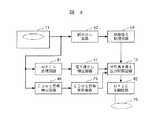
以下、再生プレーヤから再生された信号を記録ディスクに記録する場合の回路構成及びその動作について図7を用いて説明する。
図7は本発明によるコピー制御情報を備えた映像信号の処理装置のさらに他の実施例である。図において、71は再生プレーヤである。再生プレーヤ71で再生された信号中に含まれる電子透かし情報は電子透かし検出回路47で検出され、再生信号内のCGMS信号、又は電子透かし情報とCGMS信号の世代を書き換える世代書き換え及び出力制御回路72に供給される。再生信号中に含まれているCGMS信号はCGMS信号検出回路48で検出されCGMS信号更新回路73に供給され、ここで、検出されたCGMS信号は一定の規則にしたがって更新される。
ここで一定の規則とは検出された信号が一回コピー可能な信号ならばこれ以上のコピー禁止信号へ変換され、コピー自由なら何ら変更を加えず、そしてこれ以上のコピー禁止ならば記録回路の動作を止めるものである。
【0037】
CGMS信号更新回路73から出力された世代が更新されたCGMS信号は世代書き換え及び出力制御回路72に供給される。又、世代書き換え及び出力制御回路72には信号読み出し回路42及び映像信号処理回路43を通して映像信号が供給されており、世代更新されたCGMS信号、又はこのCGMS信号と電子透かし情報はこの世代書き換え及び出力制御回路72で書き換えられた後、変調回路等から構成される記録回路74を通して記録可能なディスク75、例えばRAMディスクに記録される。また、世代書き換え及び出力制御回路72では電子透かし情報と世代が更新されたCGMS信号の内容が合理的か否かをチェックする。
ここで、CGMS信号の世代更新は図3のCGMS信号31a,31bに示す2ビットの信号を“10”から“11”に変更することによって行われる。ここで世代書き換え及び出力制御回路72において電子透かし情報とCGMS信号更新回路73から出力されるCGMS信号の内容が合理的でない場合には記録を止める。
例えば、電子透かし情報がコピー禁止であり、CGMS信号もコピー禁止の場合は世代書き換え及び出力制御回路72から映像信号が出力されない。電子透かし情報がコピー可能であり、CGMS信号がコピー可能な場合は世代書き換え及び出力制御回路72から映像信号が出力され、ディスク75に記録される。
【0038】
電子透かし情報が一回のコピーが可能であり、CGMS信号が一回のコピー可能からコピー禁止に書き換え作業が行われている場合には、世代書き換え及び出力制御回路72から映像信号が出力されディスク75への記録が行われる。
電子透かし情報が一回のコピー可能からコピー禁止に書き換え作業が行われており、CGMS信号が一回のコピー可能からコピー禁止に書き換え作業が行われている場合には、世代書き換え及び出力制御回路72から映像信号が出力されてディスク75への記録作業が続行される。
ところが、電子透かし情報はコピー禁止を示しているにも拘わらず、世代更新されたCGMS信号が一回のコピー可能からコピー禁止に書き換えられる場合には本来コピー禁止だったはずのディスクに新たにCGMS信号を追加記録してこの信号を一回のコピーが可能とした場合である。
このように本来あるべきでない信号形態が検出されると世代書き換え及び出力制御回路72において二つの信号間で合理性がないとして世代書き換え及び出力制御回路72は映像信号を出力させない。
【0039】
図8は本発明によるコピー制御情報を備えた映像信号の処理装置のさらに他の実施例を示すブロック図である。図7に示すブロック図においては、MPEG解除がされていない、圧縮された信号が電子透かし検出回路47及びCGMS信号検出回路48に供給されているが、図8のブロック図ではMPEG処理回路81が設けられ、MGEGがデコードされた信号が電子透かし検出回路47に供給される。また、ディスク75に記録する場合にはMPEG圧縮回路82で再びMPEG圧縮される点が異なっているが、その他の点は同じであるため、説明を省略する。
【0040】
このようにMPEG圧縮された信号上で電子透かし情報やCGMS信号を検出する場合とMPEG圧縮処理を解除した映像信号を用いて電子透かし情報やCGMS信号を検出する場合がある。電子透かし情報の検出とCGMS信号の処理はどちらの信号でおこなっても良い。
【0041】
【発明の効果】
以上述べたように、本発明によれば映像信号の輝度信号を変えて画像に記録された電子透かし情報と、映像信号に挿入されたCGMS信号をもちて、この二つの信号が合理的な関係を示す時に再生あるいは記録を許可することによって、単独で使用する場合に比べてより確実性のあるコピー制御を行う事が可能となる。
【図面の簡単な説明】
【図1】図1は本発明によるコピー制御情報の記録装置の一実施例を示すブロック図である。
【図2】図2は電子透かし情報の埋め込み方法を説明するための画素の輝度値を直線表示した模式図である。
【図3】図3は世代管理信号が付加されたテレビジョン信号の概略の一実施例を示す模式図である。
【図4】図4は本発明によるコピー制御情報を備えた映像信号の処理装置の一実施例を示すブロック図である。
【図5】図5は本発明によるコピー制御情報を備えた映像信号の処理装置の他の実施例を示すブロック図である。
【図6】図6は本発明によるコピー制御情報を備えた映像信号の処理装置の更に他の実施例を示すブロック図である。
【図7】図7は本発明によるコピー制御情報を備えた映像信号の処理装置の更に他の実施例を示すブロック図である。
【図8】図8は本発明によるコピー制御情報を備えた映像信号の処理装置の更に他の実施例を示すブロック図である。
【符号の説明】
1…入力回路、3…変更可能範囲算出回路、5…情報埋め込み処理回路、9…加算回路、7…CGMS信号発生回路、11…色信号回路、12…出力回路、42…信号読み出し回路、43…映像信号処理回路、47…電子透かし検出回路、48…CGMS信号検出回路、49…出力制御回路、72…世代書き換え出力制御回路、73…CGMS信号更新回路、74…記録回路、81…MPEG処理回路。[0001]
BACKGROUND OF THE INVENTION
In order to clarify the reproduction control or recording control of an original image, or the origin of the image, the present invention provides other information superimposed on or embedded in image data, particularly a video signal, that is, digital watermark information and generation. The present invention relates to a recording / reproducing method, a recording / reproducing apparatus, a processing apparatus, and a recording medium for a video signal having copy control information including a management signal.
[0002]
[Prior art]
Several methods have been proposed for embedding digital watermark (water marking, data hiding, or embedding) information in a video signal, and a representative one is a technical report of the Institute of Image Information Media (ITE Technical Report Vol 21. No31). .Pp3-8 data hiding technology). As a conventional information embedding technique, it is described in Nikkei Electronics (1997) No. 683, pages 99 to 107. In these prior arts, the statistical properties of images are used to embed information in the video signal that is different from the information that the original video signal has, and this embedded information is used during playback. It is shown that the control signal for determining the origin of the original image and the further progress is obtained.
In this prior art, the statistical properties of the image are used to embed information in the image that is different from the information that the original image has in the image, and the original information is used using this embedded information during playback. It is shown that a control signal that determines the origin of the image and further progress is determined.
[0003]
[Problems to be solved by the invention]
In general, widely accepted copy control includes full copy prohibition and only one copy allowed. The latter is positioned as generation management (CGMS), and when one-time copying is permitted, this signal changes from “one-time copying” to “no more copying”. Is rewritten as a signal.
However, the above document does not describe performing copy control by combining such a technique and digital watermark information.
[0004]
It is an object of the present invention to provide a video signal recording / reproducing method, a recording / reproducing apparatus, a processing apparatus, and a recording medium having copy control information that can be easily reproduced.
Another object of the present invention is to provide a video signal recording / reproducing method, recording / reproducing apparatus, processing apparatus, and recording medium provided with copy control information such as digital watermark information and generation management signals.
Still another object of the present invention is to provide a video signal playback method, playback device, and processing device having copy control information that can prohibit the output of a playback signal when the copy control information is illegally operated. is there.
Still another object of the present invention is to provide a video signal reproduction method capable of performing copy control in consideration of generation management using copy control information included in a luminance signal of a video signal once recorded on a VTR, a video disk, or the like. Another object is to provide a playback device and a processing device.
[0005]
[Means for Solving the Invention]
To achieve the object of the present invention, a recording medium according to the present invention includes a video signal, digital watermark information embedded in the video signal and having copy control information, and CGMS for copy control inserted in the video signal. Signals are recorded. This digital watermark information is obtained by changing the luminance value of the luminance signal at a predetermined position of the video signal. Preferably, the change range of the brightness value of the brightness signal is set to a changeable range. The CGMS signal is inserted outside the scan area of the video signal. Preferably, the CGMS signal is inserted outside the scan area near the horizontal synchronization signal. Preferably, the CGMS signal is a signal having a bit number of 2 bits or more. This digital watermark information includes information of copy free, copy once, and copy prohibited. Further, this CGMS signal has any information of copy free, copy once, and copy prohibited.
[0006]
According to the recording method of the present invention, a step of generating digital watermark information by changing a luminance value at a predetermined position of a luminance signal and embedding copy control information in the luminance signal, and a CGMS signal having the copy control information is generated. And inserting it outside the scan area of the video signal.
According to the recording method of the present invention, the step of calculating a range that can be visually endured even if the luminance value of the luminance signal included in the video signal is changed, and the luminance value of the luminance signal at a predetermined position are calculated. A step of generating digital watermark information having copy control information by changing within the range; and a step of generating a CGMS signal having copy control information and inserted outside the scan area of the video signal.
Further, the recording method according to the present invention includes a step of calculating a range that can be visually endured even if the luminance value of the luminance signal included in the video signal is changed, and a luminance signal at a predetermined position, which is changed. And generating a digital watermark information having copy control information by changing the luminance value when the luminance value is within the calculated range, and having copy control information and outside the scan area of the video signal Generating a CGMS signal to be inserted.
[0007]
The reproduction method according to the present invention is a video signal comprising digital watermark information in which copy control information is embedded by changing the luminance value of the luminance signal and a CGMS signal having copy control information inserted outside the scan area of the video signal. Detecting the digital watermark information, detecting the CGMS signal, and detecting the digital watermark information in order to reproduce the digital watermark information and the CGMS signal from the recording medium and control the output of the video signal. A step of cutting off the output of the video signal when the copy control information obtained from the data and the copy control information obtained from the CGMS signal are not rational. The digital watermark signal and the CGMS signal include information on either copy prohibition information or information that can be copied once. Furthermore, the method includes a step of outputting and displaying a video signal by the once-copyable information obtained from the digital watermark information and the copy prohibition information obtained from the CGMS signal. Further, the method includes a step of outputting and displaying a video signal based on the copy prohibition information obtained from the digital watermark information and the copy prohibition information obtained from the CGMS signal. When the CGMS signal is not reproduced, there is a step of cutting off the output of the video signal.
[0008]
In the reproducing method of the present invention, the disc type is discriminated from the step of discriminating the disc type, the copy control information obtained from the digital watermark information, the copy control information obtained from the CGMS signal, and the disc type information. Includes a step of cutting off the output of the video signal. When the disc is a reproduction-only disc, the digital watermark information is a signal that can be copied once, and the CGMS signal is a signal that can be recorded once, the step of outputting the video signal is provided. A step of cutting off the output of the video signal when the disc is a recordable disc, the digital watermark information is a signal that can be copied once, and the CGMS signal is a signal that can be recorded once; Yes.
[0009]
In the reproducing method according to the present invention, the digital watermark information in which any one of copy prohibition and one-time copyable information is embedded by changing the luminance value of the luminance signal and any one of the copy-inhibition and one-time copy is possible. The digital watermark information and the CGMS signal are reproduced from the recording medium from the video signal including the CGMS signal having information, and the copy control information embedded in the electronic watermark information is detected to control the recording of the video signal. A step of detecting copy control information from the CGMS signal, a step of determining whether or not the copy control information has a reasonable relationship, and recording of the video signal only when there is a reasonable relationship. And a step of permitting. The step of determining a rational relationship is determined to be reasonable from the situation where the once copyable information obtained from the digital watermark information and the once copyable information obtained from the CGMS signal are rewritten to copy prohibition information. Further, it is determined to be reasonable from the situation where the once copyable information obtained from the digital watermark information is copy prohibited and the once copyable information obtained from the CGMS signal is rewritten to copy prohibited information.
[0010]
The recording apparatus according to the present invention calculates a changeable range calculation circuit for calculating a change range of the brightness value according to the brightness value of the brightness signal included in the video signal, and calculates the brightness value of the brightness signal at a predetermined position. An information embedding processing circuit for embedding digital watermark information having copy control information by changing within a variable range, a generation circuit for generating a CGMS signal having copy control information, and a digital watermark information embedded in the CGMS signal And an addition circuit for adding the luminance signal outside the scan area range.
[0011]
In addition, the recording apparatus according to the present invention includes a changeable range calculation circuit that calculates a change range of the brightness value according to the brightness value of the brightness signal included in the video signal, and a brightness value of the brightness signal at a predetermined position. An information embedding processing circuit for embedding digital watermark information having copy control information by changing the luminance value of the luminance signal when is within the calculated variable range, and a generating circuit for generating a CGMS signal having copy control information And an adding circuit for adding the CGMS signal to the outside of the scan area range of the luminance signal in which the digital watermark information is embedded.
[0012]
A video signal processing apparatus having copy control information according to the present invention includes a digital watermark information in which copy control information is embedded by changing a luminance value of a luminance signal and copy control information inserted outside a scan area of the video signal. A circuit for processing the video signal reproduced from the recording medium in order to reproduce the digital watermark information and the CGMS signal from the recording medium from the video signal including the CGMS signal, and to control the output of the video signal; An electronic watermark detection circuit, a CGMS signal detection circuit for detecting a CGMS signal, and an output control circuit for controlling the video signal processing circuit from the detected digital watermark information and the detected CGMS signal are provided. The output control circuit controls the video signal processing circuit to output the video signal based on the once-copyable information obtained from the digital watermark information and the copy prohibition information obtained from the CGMS signal. The output control circuit controls the video signal processing circuit to output the video signal based on the copy prohibition information obtained from the digital watermark information and the copy prohibition information obtained from the CGMS signal. The output control circuit controls the video signal processing circuit so as not to output the video signal when the CGMS signal is not detected. When the recording medium is a recordable medium, the output control circuit prevents the video signal from being output based on the once-copyable information obtained from the digital watermark information and the once-copyable information obtained from the CGMS signal. Control processing circuitry. When the recording medium is a reproduction-only medium, the output control circuit outputs a video signal based on the once-copyable information obtained from the digital watermark information and the once-copyable information obtained from the CGMS signal. Control the video signal processing circuit. This processing apparatus includes a circuit for discriminating the type of disk. When the output of the disc type discrimination circuit is a signal indicating a recordable disc, the output control circuit uses the once copyable information obtained from the digital watermark information and the once copyable information obtained from the CGMS signal to generate a video signal. The video signal processing circuit is controlled so as not to output. When the output of the disc type discrimination circuit is a signal indicating a read-only disc, the output control circuit uses the once-copyable information obtained from the digital watermark information and the once-copyable information obtained from the CGMS signal to The video signal processing circuit is controlled to output a signal.
[0013]
The processing apparatus according to the present invention includes a circuit for updating the generation of the CGMS signal and a rewriting and control circuit for controlling the output of the video signal, and controls whether or not the video signal can be output by the digital watermark signal and the CGMS signal. The rewrite and control circuit outputs a video signal from the rewrite and control circuit based on the once copyable information obtained from the digital watermark information and the once copyable information obtained from the CGMS signal, and records the CGMS signal once. The possible information is rewritten to copy prohibition information. The rewrite and control circuit outputs a video signal from the rewrite and control circuit based on the once-copyable information obtained from the digital watermark information and the once-copyable information obtained from the CGMS signal. The once recordable information is rewritten to copy prohibition, and the CGMS signal once recordable information is rewritten to copy prohibition information.
[0014]
A recording / reproducing apparatus according to the present invention records a video signal provided with copy control information including copy control bits and digital watermark information in which a control signal generated by the bits is embedded. The bit directly detected at the time of reproduction is compared with the signal from which the digital watermark information is detected, and the video signal is output only when there is a predetermined relationship. Only when the digital watermark information is detected and the signal by the directly detected bit indicates that one-generation copying is possible, the signal by the bit generation means is changed, and the changed signal, the input digital watermark recording signal and the video signal are simultaneously Recording is performed, and subsequent recording is regarded as an impossible operation. The bit is rewritten to a signal that disables further recording only when one-generation copying is possible, and is recorded simultaneously with the digital watermark recording signal and the video signal.
[0015]
The reproducing apparatus according to the present invention is recorded by a digital watermark information detecting means and a bit generating means for reproducing a video signal from a video signal on which digital watermark information is recorded and a disc on which copy control bits are written. The video signal written on the disc when the disc is for reproduction only and the digital watermark information matches the bit information by the disc discriminating unit for discriminating the disc, the disc discriminating unit for discriminating the disc, and the disc discriminating unit. Reproduce. In addition, when the disc can be recorded / reproduced by the disc discriminating means and the digital watermark information and the bit information coincide with each other and when the one-generation copy capability of the signal by the detected bit information stage is correctly changed, the video signal is output. Reproduce. When the disc is recordable and reproducible, the video signal is reproduced only when the digital watermark information is information that can be copied one generation and the information of the bit generation means is information that prohibits further copying.
[0016]
DETAILED DESCRIPTION OF THE INVENTION
DESCRIPTION OF THE PREFERRED EMBODIMENTS Embodiments of a video signal recording / reproducing method, recording / reproducing apparatus, processing apparatus, and recording medium having copy control information according to the present invention will be described below with reference to the accompanying drawings.
[0017]
First, an embodiment of a digital watermark information recording apparatus according to the present invention will be described. FIG. 1 is a block diagram showing an embodiment of a digital watermark information recording apparatus according to the present invention. In this embodiment, digital watermark information is embedded by changing the luminance of a pixel.
In FIG. 1, a video signal is input to the input circuit 1. A luminance signal is taken out from the input circuit 1 and supplied to the changeable range calculation circuit 3. Based on this luminance signal, a range that does not have much visual influence even if the luminance signal is changed is calculated. In a portion where the luminance change is large, even if the luminance signal is greatly changed, it does not change much visually. However, in a portion where the luminance change is small, it is visually noticeable unless the amount of change in luminance is reduced, so this changeable range calculation circuit 3 Then, the changeable range is calculated in consideration of this. This changeable range calculation circuit 3 can be realized by a CPU of a computer. The calculation result from the changeable range calculation circuit 3 is supplied to the information embedding
[0018]
(1) Where the change in the edge of the image is large, even if the amplitude of the edge signal is changed greatly, it does not change much visually. On the other hand, when the change in the edge of the image is small, if the amplitude of the edge signal is greatly changed, the image changes visually.
(2) The image change range is limited to a range where the image does not change visually or a range where viewing is not hindered even if the image changes visually.
When the digital watermark information is embedded in this way, an image that has a luminance different from that of the original image but does not change visually can be obtained. The changeable range calculation circuit 3 stores the luminance before application of image processing and the luminance after application for each pixel, confirms whether or not this is within the changeable range, and enters the changeable range. Only change the luminance signal.
The information embedding
A generation management
[0019]
Next, a luminance changing method in the information embedding
FIG. 2 is a schematic diagram in which luminance values of pixels are displayed in a straight line. In the figure, it is assumed that the luminance value of one pixel is from 0 to 255. In this embodiment, the value of the white circle on the straight line is a luminance corresponding to a multiple of 16, and corresponds to the embedded information “0”. The value of the black point is a point corresponding to the value of (multiple of 16 + 8), and corresponds to the embedded information “1”.
First, the basic operation of the information embedding
Next, use of the changeable range calculation circuit 3 will be described. When embedding digital watermark information, there is a case where the change in luminance of the pixel is too large and the image visually changes. In order to prevent this, the range in which the pixel value can be changed needs to be within the changeable range. For example, in FIG. 2, it is assumed that the value of the luminance Δ of a pixel is 30, and the changeable range of the luminance of the pixel is 26 to 33. In this case, when the information to be embedded is “0”, the luminance of the pixel may be changed to 32 as in the above basic operation. However, when the information to be embedded is “1”, the
[0020]
Further, a method of extracting digital watermark information from a watermark inserted image, that is, a video signal in which digital watermark information is embedded will be described. First, a pixel whose luminance value has been changed is selected. Since the position of the pixel whose luminance is changed is predetermined, it can be selected by a pulse obtained based on the horizontal synchronization signal. That is, the pixel whose luminance is changed is selected according to the same rule as the pixel selection in the information embedding
Next, for each selected pixel, the luminance signal is extracted, and whether the embedded information is “0” or “1” depending on whether the value is a multiple of 16 or a multiple of 16 + 8. Determine.
As described above, since the information embedding processing circuit 65 changes the luminance within a changeable range, the luminance may not be accurately changed to a multiple of 16 or (a multiple of 16 + 8). Therefore, an error occurs in information extraction. However, this problem can be solved by embedding the same information in a plurality of pixels and performing a majority vote in extraction.
[0021]
Next, an embodiment of the generation management signal will be described with reference to FIGS. 3 (a) and 3 (b).
FIG. 3A is a schematic diagram showing an example of an outline of a television signal in a vertical period in which a generation management signal is inserted. FIG. 3B is a partially enlarged view of FIG.
In FIG. 3A, generation management signals (abbreviated as CGMS signals) 31, 35 are inserted in a period outside the scan range at the top of the screen of the 17th and 18th horizontal synchronization periods of the
[0022]
In FIG. 3B, a
[0023]
The CGMS signal needs to represent three modes: (1) copy free, (2) copy once, (3) no more copy prohibit modes.
Also, (2) when copying is possible once, it is necessary to rewrite this signal to (3) no more copy prohibition during copying. This is called generation update.
(3) When copying is performed in a copy prohibition mode higher than this, the copy operation must be prohibited. For this purpose, the CGMS signals 31 and 35 shown in FIGS. 3A and 3B are composed of 2-bit control signals. A digital watermark and CGMS signal processing device provided in a recording device or reproduction device for copying a television signal determines whether or not reproduction is possible by viewing this CGMS signal.
The generation update means that the CGMS signal is rewritten, for example, from a bit “10” that can be copied once to a copy prohibition bit “11”.
The digital watermark information described above includes reproduction / recording control information for the original image, and information for clarifying the origin of the image, and the CGMS signal is copy-free, can be copied once, and is prohibited to copy any further. Such information is included, but in the following description, both of these information are referred to as copy control information.
Usually, it tends to be considered that it is sufficient to perform copy control using one of the control signals of the CGMS signal or the digital watermark information. However, when only one of the control signals, for example, the CGMS signal is employed. Since this signal is easily rewritten, control different from the desired copy control may be performed. In a situation where generation update has to be performed, for example, when the generation of the CGMS signal is not performed even though the copy has been performed once, the copy can be performed any number of times while being able to be copied once.
[0024]
Since the digital watermark information changes the luminance of the luminance signal included in the video signal, it is difficult to update the generation of this digital watermark information. For example, when the digital watermark information indicates that copying is possible once, it is difficult to update the generation of this signal, so copying can be performed any number of times. In this case, the second copy can be prohibited by updating the generation of the CGMS signal.
When a circuit for updating the digital watermark information is employed in a reproducing apparatus or a recording apparatus for copying, the generation of digital watermark information can be updated. In this case, copying can be prohibited or reproduction can be prohibited more clearly.
Regardless of the situation in which the CGMS signal should be updated, if the generation update of this CGMS signal is neglected, the contents of the digital watermark information and the CGMS signal will be the same. A ban can be made.
Considering such a case, copy control using digital watermark information and a CGMS signal has been considered.
[0025]
Hereinafter, copy control using digital watermark information and a CGMS signal will be described using the copy control information processing apparatus according to the present invention shown in FIG.
FIG. 4 is a block diagram showing an embodiment of a video signal processing apparatus having copy control information according to the present invention.
In FIG. 4, a
[0026]
In general, a signal read from the
[0027]
A video signal is supplied from the video
The digital watermark signal and the CGMS signal thus detected are input to the
[0028]
The details of the check will be described below.
When the
When the
In the case of a recordable disc, for example, a RAM disc, it is conceivable to copy again from a recording medium on which digital broadcasting or the like is primarily recorded. In this case, a general digital broadcast signal includes a CGMS signal that permits copying only once and digital watermark information, and the CGMS signal should be generation-renewed and copy prohibited at the time of primary recording. It is.
[0029]
When the video signal is reproduced from the recordable disc by connecting the terminal 50 to the display, it is desired to prohibit the reproduction when the reproduction signal or the CGMS signal is artificially altered.
The digital watermark information that permits one-time copying is detected from the digital
In this case, since the digital watermark information with the content that permits copying once and the CGMS signal with the content that prohibits copying are input to the
Therefore, in such a case, the
[0030]
If the CGMS signal is not detected from the CGMS
If the broadcast signal in which the digital watermark information is copy-prohibited and the CGMS signal is also copy-protected is recorded on a recordable disc by some means, the
Note that when neither the digital watermark signal nor the CGMS signal is detected, copying is not prohibited, and a signal permitting reproduction is output from the output control terminal.
[0031]
When the reproduction of the video signal on the
[0032]
When a video signal is reproduced on the display, an extraction pulse for extracting the CGMS signal is generated on the display, and the CGMS signal is extracted by the extraction pulse so that the gain control circuit does not respond to the CGMS signal. .
As described above, the
[0033]
FIG. 5 is a block diagram showing another embodiment of the copy control information processing apparatus according to the present invention. 5, blocks having the same functions as those in FIG. 4 are given the same reference numerals.
In FIG. 5, a disc
[0034]
For example, in the case of a RAM disk, digital watermark information can be recorded once, and a CGMS signal can also be recorded once. However, in the case of a RAM disk, since a digital broadcast signal or the like is already recorded, the digital watermark information can be recorded once when the digital watermark information is not changed, and the CGMS signal is updated for generations. In general, copying is prohibited, and if the CGMS signal can be copied once, it can be estimated that some fraud has occurred as described above. That is, it is necessary to permit reproduction in the case of a ROM disk and prohibit reproduction in the case of a RAM disk, regardless of the same information on both a ROM disk and a RAM disk. However, this can be prevented by supplying the
[0035]
FIG. 6 is a block diagram showing still another embodiment of a video signal processing apparatus having copy control information according to the present invention. In the figure,
[0036]
In the following, the circuit configuration and operation when a signal reproduced from a reproduction player is recorded on a recording disk will be described with reference to FIG.
FIG. 7 shows still another embodiment of a video signal processing apparatus having copy control information according to the present invention. In the figure,
Here, the certain rule is that if the detected signal is a signal that can be copied once, it is converted to a copy prohibition signal that is higher than this, and if the copy is free, no change is made. It stops the operation.
[0037]
The updated CGMS signal output from the CGMS
Here, the generation update of the CGMS signal is performed by changing the 2-bit signal shown in the CGMS signals 31a and 31b in FIG. 3 from “10” to “11”. Here, the generation rewriting and
For example, when the digital watermark information is copy-prohibited and the CGMS signal is also copy-prohibited, the video signal is not output from the generation rewriting and
[0038]
When the digital watermark information can be copied once and the CGMS signal is rewritten so that the copy is prohibited from being copied once, the video signal is output from the generation rewrite and
When the digital watermark information is rewritten to be copy-prohibited from being copyable once and the CGMS signal is being rewritten to be copy-prohibited from being copyable once, the generation rewrite and output control circuit The video signal is output from 72, and the recording operation on the
However, even though the digital watermark information indicates copy prohibition, when the generation-updated CGMS signal is rewritten from copy-capable to copy-prohibited, a new CGMS is newly added to the disk that should have been copy-prohibited. This is a case where a signal is additionally recorded and this signal can be copied once.
When a signal form that should not be present in this way is detected, the generation rewriting and
[0039]
FIG. 8 is a block diagram showing still another embodiment of a video signal processing apparatus having copy control information according to the present invention. In the block diagram shown in FIG. 7, compressed signals that have not undergone MPEG cancellation are supplied to the digital
[0040]
Thus, there are a case where digital watermark information and a CGMS signal are detected on an MPEG compressed signal, and a case where digital watermark information and a CGMS signal are detected using a video signal whose MPEG compression processing has been canceled. The detection of the digital watermark information and the processing of the CGMS signal may be performed with either signal.
[0041]
【The invention's effect】
As described above, according to the present invention, the electronic watermark information recorded in the image by changing the luminance signal of the video signal and the CGMS signal inserted in the video signal are used. By permitting reproduction or recording when indicating, it is possible to perform copy control with more certainty than when used alone.
[Brief description of the drawings]
FIG. 1 is a block diagram showing an embodiment of a copy control information recording apparatus according to the present invention.
FIG. 2 is a schematic diagram in which luminance values of pixels are linearly displayed for explaining a method of embedding digital watermark information.
FIG. 3 is a schematic diagram showing an example of an outline of a television signal to which a generation management signal is added.
FIG. 4 is a block diagram showing an embodiment of a video signal processing apparatus having copy control information according to the present invention.
FIG. 5 is a block diagram showing another embodiment of a video signal processing apparatus having copy control information according to the present invention.
FIG. 6 is a block diagram showing still another embodiment of a video signal processing apparatus having copy control information according to the present invention.
FIG. 7 is a block diagram showing still another embodiment of a video signal processing apparatus having copy control information according to the present invention.
FIG. 8 is a block diagram showing still another embodiment of a video signal processing apparatus having copy control information according to the present invention.
[Explanation of symbols]
DESCRIPTION OF SYMBOLS 1 ... Input circuit, 3 ... Changeable range calculation circuit, 5 ... Information embedding processing circuit, 9 ... Adder circuit, 7 ... CGMS signal generation circuit, 11 ... Color signal circuit, 12 ... Output circuit, 42 ... Signal readout circuit, 43 ... Video signal processing circuit, 47 ... Digital watermark detection circuit, 48 ... CGMS signal detection circuit, 49 ... Output control circuit, 72 ... Generation rewrite output control circuit, 73 ... CGMS signal update circuit, 74 ... Recording circuit, 81 ... MPEG processing circuit.
Claims (47)
Translated fromJapanesePriority Applications (1)
| Application Number | Priority Date | Filing Date | Title |
|---|---|---|---|
| JP24601698AJP3652135B2 (en) | 1997-09-17 | 1998-08-31 | Video signal recording / reproducing method, recording / reproducing apparatus, processing apparatus and recording medium having copy control information |
Applications Claiming Priority (3)
| Application Number | Priority Date | Filing Date | Title |
|---|---|---|---|
| JP9-251664 | 1997-09-17 | ||
| JP25166497 | 1997-09-17 | ||
| JP24601698AJP3652135B2 (en) | 1997-09-17 | 1998-08-31 | Video signal recording / reproducing method, recording / reproducing apparatus, processing apparatus and recording medium having copy control information |
Publications (2)
| Publication Number | Publication Date |
|---|---|
| JPH11155125A JPH11155125A (en) | 1999-06-08 |
| JP3652135B2true JP3652135B2 (en) | 2005-05-25 |
Family
ID=26537524
Family Applications (1)
| Application Number | Title | Priority Date | Filing Date |
|---|---|---|---|
| JP24601698AExpired - Fee RelatedJP3652135B2 (en) | 1997-09-17 | 1998-08-31 | Video signal recording / reproducing method, recording / reproducing apparatus, processing apparatus and recording medium having copy control information |
Country Status (1)
| Country | Link |
|---|---|
| JP (1) | JP3652135B2 (en) |
Families Citing this family (8)
| Publication number | Priority date | Publication date | Assignee | Title |
|---|---|---|---|---|
| JP3916804B2 (en)* | 1999-07-06 | 2007-05-23 | パイオニア株式会社 | Content recording medium and reproducing apparatus thereof |
| WO2001031630A1 (en)* | 1999-10-29 | 2001-05-03 | Sony Corporation | Method and apparatus for data processing, and medium storing program |
| KR100324765B1 (en)* | 2000-02-14 | 2002-02-20 | 구자홍 | Data structure, video reception method and apparatus thereof |
| JP2001344894A (en) | 2000-05-31 | 2001-12-14 | Sony Corp | Data recording medium, data recording method and device, data reproduction method and device |
| JP4649760B2 (en)* | 2000-05-31 | 2011-03-16 | ソニー株式会社 | Content / copy management system and method, information processing apparatus and method, and storage medium |
| WO2002037493A1 (en) | 2000-10-31 | 2002-05-10 | Sony Corporation | Apparatus and method for recording/reproducing audio data embedded with additive information |
| JP4029569B2 (en) | 2000-12-13 | 2008-01-09 | 株式会社日立製作所 | Digital information recording / reproducing apparatus, recording apparatus, receiving apparatus, and transmitting apparatus |
| JP2005063483A (en) | 2003-08-12 | 2005-03-10 | Pioneer Electronic Corp | Information recording/reproducing device, information recording/reproducing method and information recording/reproducing program |
- 1998
- 1998-08-31JPJP24601698Apatent/JP3652135B2/ennot_activeExpired - Fee Related
Also Published As
| Publication number | Publication date |
|---|---|
| JPH11155125A (en) | 1999-06-08 |
Similar Documents
| Publication | Publication Date | Title |
|---|---|---|
| KR100326403B1 (en) | Recording/reproducing method and apparatus, processing apparatus, and recording medium for video signal having copy control information | |
| KR100349427B1 (en) | Method and apparatus for recording and reproducing electronic watermark information, and recording medium | |
| JP4843894B2 (en) | Data recording method, data output method, and data recording and / or reproducing method | |
| US6687802B1 (en) | Outputting apparatus, outputting method, recording apparatus, recording method, reproduction apparatus, reproduction method and recording medium | |
| US6282654B1 (en) | Information signal recording/reproducing system, information signal recording device, information signal reproducing device and information signal recording/reproducing process | |
| US7031942B2 (en) | Information signal reproducing apparatus, information signal outputting apparatus, information signal reproducing method, and information signal outputting method | |
| JP4509456B2 (en) | Method and apparatus for controlling watermarking in multimedia data | |
| US6370319B1 (en) | Digital recording apparatus and method | |
| EP1017049B1 (en) | Data copying system and method, data reading apparatus, data writing apparatus and data recording medium for optionally preventing a third generation digital copy from a ROM disc | |
| EP0878794B1 (en) | Restriction of reproduction or copying of a recorded information signal | |
| KR100895045B1 (en) | Data output method and apparatus, data playback method and apparatus, data recording method and apparatus, and data recording and playback method and apparatus | |
| JP3652135B2 (en) | Video signal recording / reproducing method, recording / reproducing apparatus, processing apparatus and recording medium having copy control information | |
| US7356514B2 (en) | Reproduction apparatus and reproduction method of digital video signal or audio signal | |
| EP0955773B1 (en) | Apparatus for generating recording signal including image data and copy condition information | |
| KR20010110348A (en) | Copyright protection method, reproduction method, reproduction apparatus, recording method and recording apparatus | |
| EP1296327B1 (en) | Data record medium, content data, record medium, data recording method and apparatus, and data reproducing method and apparatus | |
| JPH11296976A (en) | Data playback device | |
| US20050057769A1 (en) | Information recording and reproducing apparatus, information recording and reproducing method and information recording and reproducing program | |
| US20060117373A1 (en) | Data processing device, data recording/reproducing device, data processing method and program | |
| JP2000082258A (en) | Data reproduction device | |
| JP3890871B2 (en) | Apparatus and method for reproducing digital video signal or audio signal | |
| JP2003308647A (en) | Information recording apparatus, information recording method, information notifying apparatus, information notifying method, information reproducing apparatus, information reproducing method, and information recording medium | |
| JP2004129288A (en) | Information recording apparatus and method, information reproducing system and method |
Legal Events
| Date | Code | Title | Description |
|---|---|---|---|
| A977 | Report on retrieval | Free format text:JAPANESE INTERMEDIATE CODE: A971007 Effective date:20041029 | |
| A131 | Notification of reasons for refusal | Free format text:JAPANESE INTERMEDIATE CODE: A131 Effective date:20041116 | |
| A521 | Written amendment | Free format text:JAPANESE INTERMEDIATE CODE: A523 Effective date:20050113 | |
| TRDD | Decision of grant or rejection written | ||
| A01 | Written decision to grant a patent or to grant a registration (utility model) | Free format text:JAPANESE INTERMEDIATE CODE: A01 Effective date:20050208 | |
| A61 | First payment of annual fees (during grant procedure) | Free format text:JAPANESE INTERMEDIATE CODE: A61 Effective date:20050222 | |
| FPAY | Renewal fee payment (event date is renewal date of database) | Free format text:PAYMENT UNTIL: 20090304 Year of fee payment:4 | |
| FPAY | Renewal fee payment (event date is renewal date of database) | Free format text:PAYMENT UNTIL: 20100304 Year of fee payment:5 | |
| FPAY | Renewal fee payment (event date is renewal date of database) | Free format text:PAYMENT UNTIL: 20110304 Year of fee payment:6 | |
| FPAY | Renewal fee payment (event date is renewal date of database) | Free format text:PAYMENT UNTIL: 20110304 Year of fee payment:6 | |
| FPAY | Renewal fee payment (event date is renewal date of database) | Free format text:PAYMENT UNTIL: 20120304 Year of fee payment:7 | |
| FPAY | Renewal fee payment (event date is renewal date of database) | Free format text:PAYMENT UNTIL: 20130304 Year of fee payment:8 | |
| FPAY | Renewal fee payment (event date is renewal date of database) | Free format text:PAYMENT UNTIL: 20130304 Year of fee payment:8 | |
| FPAY | Renewal fee payment (event date is renewal date of database) | Free format text:PAYMENT UNTIL: 20140304 Year of fee payment:9 | |
| S111 | Request for change of ownership or part of ownership | Free format text:JAPANESE INTERMEDIATE CODE: R313111 | |
| LAPS | Cancellation because of no payment of annual fees |