JP3650361B2 - Orthopedic implant assembly - Google Patents
Orthopedic implant assemblyDownload PDFInfo
- Publication number
- JP3650361B2 JP3650361B2JP2001508881AJP2001508881AJP3650361B2JP 3650361 B2JP3650361 B2JP 3650361B2JP 2001508881 AJP2001508881 AJP 2001508881AJP 2001508881 AJP2001508881 AJP 2001508881AJP 3650361 B2JP3650361 B2JP 3650361B2
- Authority
- JP
- Japan
- Prior art keywords
- head
- assembly
- stop member
- perforation
- stabilizing element
- Prior art date
- Legal status (The legal status is an assumption and is not a legal conclusion. Google has not performed a legal analysis and makes no representation as to the accuracy of the status listed.)
- Expired - Lifetime
Links
Images


Classifications
- A—HUMAN NECESSITIES
- A61—MEDICAL OR VETERINARY SCIENCE; HYGIENE
- A61B—DIAGNOSIS; SURGERY; IDENTIFICATION
- A61B17/00—Surgical instruments, devices or methods
- A61B17/56—Surgical instruments or methods for treatment of bones or joints; Devices specially adapted therefor
- A61B17/58—Surgical instruments or methods for treatment of bones or joints; Devices specially adapted therefor for osteosynthesis, e.g. bone plates, screws or setting implements
- A61B17/68—Internal fixation devices, including fasteners and spinal fixators, even if a part thereof projects from the skin
- A61B17/80—Cortical plates, i.e. bone plates; Instruments for holding or positioning cortical plates, or for compressing bones attached to cortical plates
- A61B17/8033—Cortical plates, i.e. bone plates; Instruments for holding or positioning cortical plates, or for compressing bones attached to cortical plates having indirect contact with screw heads, or having contact with screw heads maintained with the aid of additional components, e.g. nuts, wedges or head covers
- A61B17/8042—Cortical plates, i.e. bone plates; Instruments for holding or positioning cortical plates, or for compressing bones attached to cortical plates having indirect contact with screw heads, or having contact with screw heads maintained with the aid of additional components, e.g. nuts, wedges or head covers the additional component being a cover over the screw head
- A—HUMAN NECESSITIES
- A61—MEDICAL OR VETERINARY SCIENCE; HYGIENE
- A61B—DIAGNOSIS; SURGERY; IDENTIFICATION
- A61B17/00—Surgical instruments, devices or methods
- A61B17/56—Surgical instruments or methods for treatment of bones or joints; Devices specially adapted therefor
- A61B17/58—Surgical instruments or methods for treatment of bones or joints; Devices specially adapted therefor for osteosynthesis, e.g. bone plates, screws or setting implements
- A61B17/68—Internal fixation devices, including fasteners and spinal fixators, even if a part thereof projects from the skin
- A61B17/80—Cortical plates, i.e. bone plates; Instruments for holding or positioning cortical plates, or for compressing bones attached to cortical plates
- A—HUMAN NECESSITIES
- A61—MEDICAL OR VETERINARY SCIENCE; HYGIENE
- A61B—DIAGNOSIS; SURGERY; IDENTIFICATION
- A61B17/00—Surgical instruments, devices or methods
- A61B17/56—Surgical instruments or methods for treatment of bones or joints; Devices specially adapted therefor
- A61B17/58—Surgical instruments or methods for treatment of bones or joints; Devices specially adapted therefor for osteosynthesis, e.g. bone plates, screws or setting implements
- A61B17/68—Internal fixation devices, including fasteners and spinal fixators, even if a part thereof projects from the skin
- A61B17/70—Spinal positioners or stabilisers, e.g. stabilisers comprising fluid filler in an implant
- A61B17/7059—Cortical plates
- A—HUMAN NECESSITIES
- A61—MEDICAL OR VETERINARY SCIENCE; HYGIENE
- A61B—DIAGNOSIS; SURGERY; IDENTIFICATION
- A61B17/00—Surgical instruments, devices or methods
- A61B17/56—Surgical instruments or methods for treatment of bones or joints; Devices specially adapted therefor
- A61B17/58—Surgical instruments or methods for treatment of bones or joints; Devices specially adapted therefor for osteosynthesis, e.g. bone plates, screws or setting implements
- A61B17/68—Internal fixation devices, including fasteners and spinal fixators, even if a part thereof projects from the skin
- A61B17/80—Cortical plates, i.e. bone plates; Instruments for holding or positioning cortical plates, or for compressing bones attached to cortical plates
- A61B17/8052—Cortical plates, i.e. bone plates; Instruments for holding or positioning cortical plates, or for compressing bones attached to cortical plates immobilised relative to screws by interlocking form of the heads and plate holes, e.g. conical or threaded
- A—HUMAN NECESSITIES
- A61—MEDICAL OR VETERINARY SCIENCE; HYGIENE
- A61B—DIAGNOSIS; SURGERY; IDENTIFICATION
- A61B17/00—Surgical instruments, devices or methods
- A61B17/56—Surgical instruments or methods for treatment of bones or joints; Devices specially adapted therefor
- A61B17/58—Surgical instruments or methods for treatment of bones or joints; Devices specially adapted therefor for osteosynthesis, e.g. bone plates, screws or setting implements
- A61B17/68—Internal fixation devices, including fasteners and spinal fixators, even if a part thereof projects from the skin
- A61B17/84—Fasteners therefor or fasteners being internal fixation devices
- A61B17/86—Pins or screws or threaded wires; nuts therefor
- A61B17/8605—Heads, i.e. proximal ends projecting from bone
- A—HUMAN NECESSITIES
- A61—MEDICAL OR VETERINARY SCIENCE; HYGIENE
- A61F—FILTERS IMPLANTABLE INTO BLOOD VESSELS; PROSTHESES; DEVICES PROVIDING PATENCY TO, OR PREVENTING COLLAPSING OF, TUBULAR STRUCTURES OF THE BODY, e.g. STENTS; ORTHOPAEDIC, NURSING OR CONTRACEPTIVE DEVICES; FOMENTATION; TREATMENT OR PROTECTION OF EYES OR EARS; BANDAGES, DRESSINGS OR ABSORBENT PADS; FIRST-AID KITS
- A61F2/00—Filters implantable into blood vessels; Prostheses, i.e. artificial substitutes or replacements for parts of the body; Appliances for connecting them with the body; Devices providing patency to, or preventing collapsing of, tubular structures of the body, e.g. stents
- A61F2/02—Prostheses implantable into the body
- A61F2/30—Joints
- A61F2002/30001—Additional features of subject-matter classified in A61F2/28, A61F2/30 and subgroups thereof
- A61F2002/30316—The prosthesis having different structural features at different locations within the same prosthesis; Connections between prosthetic parts; Special structural features of bone or joint prostheses not otherwise provided for
- A61F2002/30329—Connections or couplings between prosthetic parts, e.g. between modular parts; Connecting elements
- A61F2002/30476—Connections or couplings between prosthetic parts, e.g. between modular parts; Connecting elements locked by an additional locking mechanism
- A61F2002/30495—Connections or couplings between prosthetic parts, e.g. between modular parts; Connecting elements locked by an additional locking mechanism using a locking ring
- A—HUMAN NECESSITIES
- A61—MEDICAL OR VETERINARY SCIENCE; HYGIENE
- A61F—FILTERS IMPLANTABLE INTO BLOOD VESSELS; PROSTHESES; DEVICES PROVIDING PATENCY TO, OR PREVENTING COLLAPSING OF, TUBULAR STRUCTURES OF THE BODY, e.g. STENTS; ORTHOPAEDIC, NURSING OR CONTRACEPTIVE DEVICES; FOMENTATION; TREATMENT OR PROTECTION OF EYES OR EARS; BANDAGES, DRESSINGS OR ABSORBENT PADS; FIRST-AID KITS
- A61F2220/00—Fixations or connections for prostheses classified in groups A61F2/00 - A61F2/26 or A61F2/82 or A61F9/00 or A61F11/00 or subgroups thereof
- A61F2220/0025—Connections or couplings between prosthetic parts, e.g. between modular parts; Connecting elements
Landscapes
- Health & Medical Sciences (AREA)
- Orthopedic Medicine & Surgery (AREA)
- Surgery (AREA)
- Life Sciences & Earth Sciences (AREA)
- Heart & Thoracic Surgery (AREA)
- Animal Behavior & Ethology (AREA)
- Engineering & Computer Science (AREA)
- Biomedical Technology (AREA)
- Neurology (AREA)
- Medical Informatics (AREA)
- Molecular Biology (AREA)
- Nuclear Medicine, Radiotherapy & Molecular Imaging (AREA)
- General Health & Medical Sciences (AREA)
- Public Health (AREA)
- Veterinary Medicine (AREA)
- Prostheses (AREA)
- Surgical Instruments (AREA)
- Orthopedics, Nursing, And Contraception (AREA)
Abstract
Description
Translated fromJapanese【0001】
【発明の属する技術分野】
本発明は、一般に、医療装置の分野、特に、骨片を接合するための整形インプラント及びその使用方法に関する。
【0002】
【従来の技術及び発明が解決しようとする課題】
種々の医療装置が骨片の接合、例えば、骨折、脊髄疾患、あるいは、脊髄椎間板の移動に追随する脊髄の融合の処理に必要とされている。骨片を接合するために使用される整形インプラントは、ロッド、プレート、及びネジを含む。ロッド及びプレートの場合、インプラントは、骨に接着して固定することを含む種々の方法を用いて骨に取り付けられる。一般に、骨は、ネジを保持し、ネジを締め付ける中空シャンクを有するアンカーを保持するために穿孔される。しかしながら、1つの欠点は、時間が経てば、インプラントが緩んで外れる傾向にあるということである。
【0003】
本発明の目的は、骨に永久に安定して取り付けられるように骨片を接合するための整形インプラントを提供することにある。
【0004】
【課題を解決するための手段】
本発明は、前記目的を達成するため、前方表面、後方表面、及び、少なくとも1つの穿孔を有し、該穿孔は、前方部、該前方部の内径寸法よりも小さな内径寸法を有する後方部、及び、前記前方部に形成された溝を有する安定要素と、前記安定要素の穿孔の前方部に於ける内径寸法よりも小さい内径寸法の横断通路を有し、前記穿孔の溝内に少なくとも部分的に配置された停止部材とを備えた整形インプラントアセンブリであって、前記停止部材は、前記穿孔の前方部の溝に部分的にスライド可能に配置され、前記穿孔内に第1横断通路としての内径寸法を部分的に画定する第1形状から、前記第1横断通路よりも大きい内径寸法で、第1形状に復帰可能な第2横断通路となる第2形状へと前記溝内で膨張可能であり、一体化された長尺本体及びヘッドを有する固定要素を備え、該固定要素は、前記第1形状の停止部材の第1横断通路としての内径寸法を有すると共に、前記安定要素の穿孔の後方部の内径寸法よりも大きな最大内径寸法を有し、前記ヘッドが通過する際、溝内で第1形状から第2形状へと停止部材を膨張させることにより、横断通路の内径寸法を増大させるように形成された後方表面を有し、前記ヘッドを停止部材と穿孔の後方部の小径寸法との間に配置する際、前記溝内で停止部材を膨張させることなく停止部材の後方表面に係合するように形成された前方表面を有する構成としたものである。
【0005】
前記安定要素は、一般に、プレート又はロッドからなり、前方表面の第1開口、後方表面の第2開口、及び、第1開口から第2開口に延びる横断通路を有する少なくとも1つの穿孔を備える。用語後方は、アセンブリが取り付けられる骨に近いアセンブリの内部を意味するものと理解されるべきで、用語前方は、骨から離れたアセンブリの外部を意味するものと理解されるべきである。
【0006】
一実施形態では、前記停止部材は、可逆的に膨張可能な通路を画定し、非圧縮すなわち小径の通路形状に付勢されている。一実施形態では、付勢停止部材は、可逆的に膨張可能な内径を有する環状カラーで構成されている。前記付勢停止部材は、前記固定要素が前記安定要素の横断通路内に位置した後、前記横断通路内の溝に位置決めされるように形成してもよい。これに代えて、本発明の好ましい実施形態では、前記付勢停止部材は、前記固定要素が停止部材の通路を介して前記安定要素の前方表面から前記横断通路の後方部に後方へ通過可能とするように形成されている。他の実施形態では、前記付勢停止部材は、前記横断通路内で前記安定要素に固定されると共に、偏向可能である。偏向停止部材は、前記固定要素のヘッドが停止部材によって画定された通路を膨張させるために偏向停止部材を介して後方に移動する際、可逆的に変形する。前記偏向停止部材は、非偏向又は小径通路形状に付勢される。前記停止部材は、前記固定要素が前記横断通路の後方部から前方に後退することを阻止する。この結果、前記固定要素は、前記安定要素を骨に永久的に取り付ける。
【0007】
前記固定要素は、骨に取り付けるように形成されており、大略、長尺本体及びこの本体の一端部に一体化されるヘッドから構成されている。用語一体化は、前記固定要素が、前記ヘッドと前記本体との間に相対的な動きを生じさせないように本体に固定されたヘッドを備えた1片のユニットであることを意味するものと理解されるべきである。一実施形態では、前記固定要素は、ネジ、ピン、及び爪のいずれかから選択される。本発明の好ましい実施形態では、前記固定要素が前進する前に、前記カラーが前記安定要素の溝内に収容され、前記固定要素のヘッドは、カラーに接触し、前記安定要素の横断通路の後方部に配置される際、徐々に膨張するように形成された後方表面を有する。本発明の好ましい実施形態では、前記固定要素のヘッドは、湾曲した後方表面を有する。しかしながら、傾斜した後方表面を含む他の適切な形状を使用してもよい。
【0008】
また、本発明は、整形インプラントアセンブリを患者の骨に取り付ける方法を含む。骨は、一般に、例えば、骨に穴を空ける、及び/又は穴に雌ネジを立てることにより固定要素の本体を保持するために準備される。方法は、大略、非圧縮形状で前記安定要素の溝内に停止部材を備え、骨の表面に対して安定要素の後方表面を位置決めする工程、前記固定要素の本体を横断通路に導く工程、前記停止部材を介して固定要素のヘッドを後方に移動させる工程、前記停止部材を膨張させる工程、前記停止部材が収縮してより小さな横向き、すなわち非膨張直径の形状に復帰するように、固定要素のヘッドを停止要素の後方に進ませることによって安定要素を骨に取り付ける工程からなる。前記固定要素のヘッドは、停止部材と前記安定要素の第2開口との間の横断通路内に配置され、前記固定要素の本体は、患者の骨の中に配置される。他の実施形態では、前記停止部材は、前記固定要素のヘッドが横断通路の後方部に位置した後、前記溝内に配置される。前記安定要素は、前記固定要素によって骨に取りつけられ、骨に取り付けられて前記横断通路内に保持される。
【0009】
本発明の他の実施形態では、前記固定要素のヘッドは、可逆的に圧縮可能であり、前記停止部材は、横断通路の前方部に固定される。前記停止部材は固定径で通路を画定するが、前記固定要素のヘッドの圧縮形状は、前記停止部材よりも小さな直径を有するので、前記ヘッドは停止部材の通路を介して通過可能である。非圧縮形状では、前記固定要素のヘッドは、前記停止要素及び前記安定要素の第2開口よりも大きな直径を有するので、前記ヘッドは、停止部材の後方に進み、停止部材と第2開口の間の横断通路内に保持される。
【0010】
前記整形インプラントアセンブリを骨に正確に配置することを容易にするために、前記カラーと前記安定要素の第2開口との間の横断通路が形成されているので、前記固定要素は周方向に移動可能であり、前記固定要素の本体は、患者の骨の中にある角度で配置される。
【0011】
本発明のアセンブリでは、固定要素は、固定要素のヘッドと停止部材の相互作用によって骨から後退することを阻止される。この結果、ネジを保持するために骨に注入される分離アンカー手段は必要でなく、結果的な骨のロスと、アンカーを注入するために必要とされる手術時間とが不要となる。さらに、好ましい実施形態では、前記停止部材は、処理の最初に横断通路内にあるので、外科医は、停止部材の通路を介して骨内に固定要素を前進させる単一動作でインプラントアセンブリを骨に取り付けることができる。このため、本発明のインプラントアセンブリは、アセンブリを骨に取り付けるために必要とされる時間を削減し、改善されたインプラントの性能を提供する。
【0012】
本発明の整形インプラントアセンブリは、骨に永久的に取り付けることができ、前記固定要素は、安定要素内に保持される固定要素のヘッドのため、骨から顕著に後退することを阻止される。これら及び他の本発明の利点は、後述する本発明の詳細な説明及び添付図面からさらに明らかにされる。
【0013】
【発明の実施の形態】
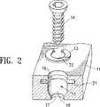
図1は、本発明の整形インプラントアセンブリ10の一実施形態を示し、大略、穿孔13内で付勢された停止部材12を備えた安定要素11と、患者の骨15に固定するために形成された固定要素14とを備えている。図1に示す実施形態では、付勢された停止部材は環状カラーからなるが、種々の適切な部材、例えば、横断通路(図示せず)内に延びるように付勢された収縮性のある1以上の指状突起を使用してもよい。
【0014】
図1のアセンブリの部分破断図を示す図2に最適に図示されるように、安定要素の穿孔13は、安定要素の前方表面の第1開口16、安定要素の後方表面の第2開口17、そこに延びる横断通路18、及び、横断通路の前方部の溝21を有する。環状カラー12は、通路22を画定し、溝21内に収容されるように形成され、可逆的に膨張可能な内外径を有する。図3、3−3線断面図、及び3A−3A線断面図に示すように、環状カラー12は、溝よりも小さく、横断通路よりも大きな非膨張外径に付勢されることにより溝内に収容されている。カラーの膨張した外径が溝径よりも小さく、かつ、高さ寸法が溝高さよりも小さいので、カラーはそこで膨張可能である。
【0015】
固定要素14は、長尺本体23と、この本体23の一端に固定された一体化ヘッド24を有する。図1に示す本発明の好ましい実施形態では、固定要素はネジで構成されている。固定要素のヘッドは、溝内に収容されたカラーの通路22を介してカラーの前方から後方に移動可能となるように形成されており、カラー12の後方表面と第2開口すなわち安定要素の後方開口17との間で横断通路18の後方部25内に保持されている。図1に示す実施形態では、固定要素のヘッドは、凸形状で、前方表面よりも小径の湾曲後方表面26を有する。湾曲後方表面26は、ヘッドが後方に移動する際、カラーに接触して膨張させるために、カラーの非膨張内径よりも小さく、かつ、カラーの通路内に配置可能である最小外径を有する。
【0016】
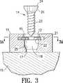
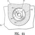
図3−5は患者の骨へのアセンブリの付属品を示す。図3に示すように、安定要素は、骨15の表面に位置し、固定要素14の本体の後方端は安定要素の横断通路内に配置されている。固定要素のヘッド24は、膨張したカラーと、カラーの通路を介して部分的に移動される固定要素のヘッドとを示す図4に図示されるように、カラー12の通路22内を後方に進み、そこでカラーの内径を膨張させるためにカラーの内面に対して径方向の膨張力を付与する。図4の矢印は、固定要素のヘッドがそこを通過する際のカラーの膨張を図示している。図4Aは図4の4A−4A線断面図を示す。カラーの膨張した内径は、固定要素のヘッドをカラーを介して後方に通過可能とするために、固定要素のヘッドの最大径よりも大きい。固定要素のヘッドは、カラーの後方に進み、横断通路の後方部25に進入するので、カラーは図5に示すように固定要素のヘッドの最大径よりも小さな非膨張内径を有する非膨張形状に復帰する。図5に示す実施形態では、固定要素のヘッドの平坦な前方表面は、カラーの非膨張内径よりも大きな直径を有し、カラーの後方表面は横断通路の長軸に垂直である。このため、ヘッドの前方表面はカラーを膨張させることなく、カラーの後方表面に密着し、固定要素が横断通路の後方部から前方に移動することを阻止される。図5に示す実施形態では、横断通路の後方部はヘッドの湾曲後方表面に適合するように湾曲され、固定要素と安定要素の間の接触を最大とする。横断通路の後方部の湾曲表面とヘッドの後方表面は同一の曲率半径を有し、ヘッドの湾曲表面の直径が十分に大きければ、横断通路を画定する壁面がヘッドをその湾曲後方表面の外周面に接触させるが、ヘッドの湾曲表面の直径が十分に小さければ、ヘッドは横断通路内に移動可能である。固定要素のヘッドが横断通路の後方部25内に配置されることにより、固定要素の本体は患者の骨に埋め込まれて固定される。
【0017】
図5に示す実施形態では、横断通路の後方部25は固定要素のヘッド24よりも十分に長いので、ヘッドは前方及び後方に移動でき、これにより、横断通路の後方部内を長手方向に移動可能である。さらに、固定要素23の本体は、安定要素の第2開口17よりも小さい直径を有し、第2開口17内を左右すなわち内側横方向に移動可能である。この結果、固定要素は、図6に示すように、横断通路の後方部25内で、安定要素内のカラー12と第2開口17の間を軸方向に移動可能である。これにより、固定要素は横断通路の長軸に対してある角度をなして傾斜し、骨の表面に対してある角度で骨内に固定要素の本体を進ませることにより、骨内の所望の位置に固定要素を位置させることが容易となる。固定要素は、横断通路の長軸に対して約45°、好ましくは約20°まで回転可能である。
【0018】
停止部材12は、改良可能で、チタニウムや、ニッケルチタン合金等の超弾性あるいは擬似弾性材料で形成されるのが好ましい。停止部材の非膨張内径は、約0.1〜約40mm、好ましくは約0.5〜約20mmで、固定要素のヘッドの最大横幅以下の約0.05〜約20mm、好ましくは約0.1〜約15mmである。停止部材の非膨張外径は約0.2〜約50mm、好ましくは約1.0から約30mmである。停止部材の膨張内径は、約0.15〜約50mm、好ましくは約0.75〜約30mmであり、停止部材の膨張外径は、約0.5〜約60mm、好ましくは約1.5〜約40mmである。停止部材の高さは、約0.01〜約5mm、好ましくは約0.05〜約3mmである。
【0019】
図7−12は本発明の他の実施形態を示し、大略、固定要素30と、停止部材が横断通路18の溝内に収容されない以外は図1に示す実施形態の安定要素と同様な安定要素31とを備えている。これに代えて、停止部材32は横断通路の前方部に設けてもよく、安定要素と共に、あるいは、そこに固定された別部材として一体的に形成してもよい。図7に示す実施形態では、停止部材は横断通路の前方端のカラーであり、安定要素31の第1開口16を画定する。固定要素30は、縦長本体33と、圧縮及び非圧縮形状を有する本体の一端部に固定されたヘッド34とを備える。図7に示す実施形態では、ヘッドは、固定要素の本体に固定された前方端を有する周囲に配置された部材36を画定する多数の溝35を備える。周囲に配置された部材36は、カラーの内径以下の直径を有する圧縮形状を形成するためにヘッドの長軸に向かって径方向に移動可能な前方端を有する。図8は、カラーによって画定された通路内で圧縮形状の固定要素のヘッドを示す。図9は図8の9−9線断面図を示す。図10は、カラーの後方に進み、横断通路の後方部に侵入し、そこでカラーの径方向の圧縮力の開放によって周囲に配置された部材36を非圧縮形状に復帰させる固定要素のヘッドを示す。図11は、仮想図示された第1開口16を備えた図10の11−11線断面図を示す。固定要素は、図1に示す実施形態に関して上述するように、かつ、図12に示すように、横断通路の後方部25内を周方向及び長手方向に移動可能である。
【0020】
図13−15は、本発明の他の実施形態を示し、大略、横断通路の前方部に設けた偏向可能な停止部材42以外は、図1に示す実施形態の安定要素と同様な安定要素41を備えており、停止部材は安定要素と一体化してもよいし、そこに固定した別部材としてもよい。図13に示す実施形態では、停止部材は、周囲に配置された部材44を画定する多数の溝43と、先細すなわち傾斜された、後方の軸方向に弾性変形する前方表面とを有するので、固定要素がカラーを介して後方に移動した際、カラーは後方に偏向する。この結果、周囲に配置された部材44は、カラーによって画定された中央通路45に向かって傾斜する楔形状と高さを有し、固定要素のヘッドを移動させると共に、通路45を可逆的に膨張させることを容易にする。図13に示す実施形態では、カラーは横断通路の前方端に安定要素を一体化され、安定要素41に第1開口16を形成する。固定要素は、図1に示す実施形態に関して上述し、かつ、図13に示す固定要素14と同一又は同様としてもよい。しかしながら、図7に示す実施形態に関して上述した圧縮及び非圧縮形状を有するヘッド34を備えた固定要素も同様に使用してもよい。図15は、部分的に仮想図示した固定要素14のヘッドを備え、図14に示すアセンブリの15−15線断面平面図を示す。横断通路の後方部25で周方向及び長手方向に固定部材を移動させる点は上述の通りである。
【0021】
安定要素は、チタニウムやステンレス鋼等の金属で形成されるのが好ましい。一般に、安定要素の長さは約7〜約300mm、好ましくは約13〜約200mmで、安定要素の幅は、約5〜約50mm、好ましくは約10〜約30mmである。一般に、安定要素の高さは、約0.5〜約10mm、好ましくは約1.0〜約6.0mmであるが、安定要素の寸法はアセンブリが使用されるべき応用例に応じて変化する。
【0022】
固定要素は、チタニウムやステンレス鋼等の金属で形成されるのが好ましい。固定要素のヘッドは、例えば、固定要素を骨に進ませるために工具に取り外し可能に連結できるように六角形の開口を形成されている。固定要素の本体は、約2〜約50mm、好ましくは約5〜約20mmの長さを有し、固定要素のヘッドは、約0.05〜約1.5mm、好ましくは約0.5〜約1.0mmの長さを有する。種々の適切な固定要素を使用してもよいことが当業者に理解され、特に医療環境での使用に最適な固定要素は熟練者によく知られている。例えば、骨からネジが抜けることを制限するために、高いネジピッチを使用するようにしてもよい。
【0023】
本発明のアセンブリは、骨折した骨片や脊髄に付随する椎間板を固定することを含む、種々の医療手術への使用に適している。図示された実施形態では、安定要素はプレートで構成されているが、ロッド等の他の適切な要素を使用しても構わない。さらに、安定要素は、骨あるいはその骨が接着される骨の表面に適合するように形成してもよい。例えば、安定要素の好ましい実施形態は凹状の後方表面を備えたプレートからなり、脊髄に取り付けられるように形成されている。
【0024】
本発明は、好ましい実施形態として記載されているが、変形や改良が本発明の範囲から離れることなく創作されることは当業者に理解される。例えば、停止部材が主にカラーによって説明されているが、他の形態であっても使用可能である。さらに、特徴が一実施形態に関して説明されているが、一実施形態の特徴を他の実施形態で使用することもできる。
【図面の簡単な説明】
【図1】 本発明の特徴を具体化した整形インプラントアセンブリの斜視図である。
【図2】 図1に示す整形インプラントアセンブリの部分破断図である。
【図3】 図1に示す整形インプラントアセンブリの3−3線断面図である。
【図3A】 図3の3A−3A線断面図である。
【図4】 固定要素が患者の骨に進められた状態に於ける図3に示す整形インプラントアセンブリである。
【図4A】 図4の4A−4A線断面図である。
【図5】 安定要素の横断通路の後方部に進んだ固定要素を備えた図3に示す整形インプラントアセンブリである。
【図6】 患者の骨内に縦方向に配置された固定要素を備えた図3に示す整形インプラントアセンブリである。
【図7】 本発明の特徴を具体化した圧縮されたヘッドを備えた固定要素を有する整形インプラントアセンブリの部分破断図である。
【図8】 固定要素が患者の骨に進められた状態に於ける図7に示す整形インプラントアセンブリである。
【図9】 図8の9−9線断面図である。
【図10】 安定要素の横断通路の前方部に進んだ固定要素を備えた図7に示す整形インプラントアセンブリである。
【図11】 図10の11−11線断面図である。
【図12】 患者の骨内に縦方向に配置された固定要素を備えた図7に示す整形インプラントアセンブリである。
【図13】 本発明の特徴を具体化した偏向可能な停止部材を有する整形インプラントアセンブリである。
【図14】 安定要素の横断通路の後方部に進んだ固定要素を備えた図13に示す整形インプラントアセンブリである。
【図15】 図14の15−15線断面図である。
【符号の説明】
10…整形インプラントアセンブリ
11…安定要素
12…停止部材
13…穿孔
14…固定要素
15…骨
18…横断通路
25…後方部[0001]
BACKGROUND OF THE INVENTION
The present invention relates generally to the field of medical devices, and more particularly to orthopedic implants for joining bone fragments and methods of use thereof.
[0002]
[Prior art and problems to be solved by the invention]
Various medical devices are required for the treatment of bone piece joints, such as fractures, spinal cord disease, or spinal fusion that follows spinal disc movement. Orthopedic implants used to join bone fragments include rods, plates, and screws. In the case of rods and plates, the implant is attached to the bone using a variety of methods including bonding and fixing to the bone. Generally, bone is drilled to hold an anchor with a hollow shank that holds the screw and tightens the screw. However, one drawback is that over time, the implant tends to loosen and come off.
[0003]
An object of the present invention is to provide an orthopedic implant for joining bone fragments so that they can be permanently and stably attached to bone.
[0004]
[Means for Solving the Problems]
To achieve the object, the present invention has afront surface, a rear surface, and at least one perforation, the perforation having a front portion, a rear portion having an inner diameter dimension smaller than an inner diameter dimension of the front portion, And a stabilizing element having a groove formed in the front part, and a transverse passage having an inner diameter smaller than an inner diameter dimension in the front part of the perforation of the stabilizing element, and at least partially in the groove of the perforation An orthopedic implant assembly comprising: a stop member disposed in the perforation, wherein the stop member is partially slidably disposed in a groove in an anterior portion of the perforation and has an inner diameter as a first transverse passage in the perforation Inflatable in the groove from a first shape that partially defines the dimension to a second shape that is a larger inner diameter than the first transverse passage and a second transverse passage that can be returned to the first shape. , Integrated long body And a fixing element having a head, the fixing element having an inner diameter dimension as a first transverse passage of the stop member of the first shape and having a maximum inner diameter larger than an inner diameter dimension of a rear portion of the perforation of the stabilizing element And having a rear surface configured to increase the inner diameter dimension of the transverse passage by expanding the stop member from a first shape to a second shape in the groove as the head passes. A front surface formed to engage the rear surface of the stop member without expanding the stop member in the groove when the head is disposed between the stop member and the small diameter dimension of the rear portion of the perforation. It is set as the structure which has.
[0005]
The stabilizing element generally comprises a plate or rod and comprises at least one perforation having a first opening on the front surface, a second opening on the rear surface, and a transverse passage extending from the first opening to the second opening. The term posterior should be understood to mean the interior of the assembly close to the bone to which the assembly is attached, and the term anterior should be understood to mean the exterior of the assembly away from the bone.
[0006]
In one embodiment, the stop member defines a reversibly inflatable passage and is biased into an uncompressed or small diameter passage shape. In one embodiment, the bias stop member comprises an annular collar having an inner diameter that is reversibly expandable. The bias stop member may be formed so that the fixing element is positioned in a groove in the transverse passage after the fixing element is located in the transverse passage of the stabilizing element. Alternatively, in a preferred embodiment of the present invention, the bias stop member is configured such that the fixing element can pass rearward from the front surface of the stabilizing element to the rear portion of the transverse passage through the passage of the stop member. It is formed to do. In another embodiment, the bias stop member is fixed to the stabilizing element and deflectable within the transverse passage. The deflection stop member is reversibly deformed when the head of the fixed element moves backward through the deflection stop member to expand the passage defined by the stop member. The deflection stop member is biased into a non-deflection or small diameter passage shape. The stop member prevents the fixing element from retracting forward from the rear part of the transverse passage. As a result, the anchoring element permanently attaches the stabilizing element to the bone.
[0007]
The fixing element is formed so as to be attached to a bone, and generally includes a long main body and a head integrated with one end of the main body. The term integration is understood to mean that the fixing element is a one-piece unit with a head fixed to the body so as not to cause relative movement between the head and the body. It should be. In one embodiment, the securing element is selected from any of a screw, a pin, and a claw. In a preferred embodiment of the invention, before the fixing element is advanced, the collar is received in the groove of the stabilizing element, the head of the fixing element contacts the collar and behind the transverse passage of the stabilizing element. And a rear surface formed to gradually expand when disposed on the portion. In a preferred embodiment of the invention, the head of the fixing element has a curved rear surface. However, other suitable shapes including an inclined rear surface may be used.
[0008]
The present invention also includes a method of attaching an orthopedic implant assembly to a patient's bone. The bone is generally prepared to hold the body of the anchoring element, for example by drilling a hole in the bone and / or raising an internal thread in the hole. The method comprises a stop member in a generally uncompressed shape in the groove of the stabilizing element, positioning the posterior surface of the stabilizing element relative to the surface of the bone, guiding the body of the fixation element to the transverse passage, Moving the head of the fixing element back through the stop member, expanding the stop member, and retracting the stop member to return to a smaller lateral, i.e. non-expanded diameter shape. It consists in attaching the stabilizing element to the bone by advancing the head behind the stop element. The head of the fixation element is disposed in a transverse passage between a stop member and the second opening of the stabilization element, and the body of the fixation element is disposed in a patient's bone. In another embodiment, the stop member is arranged in the groove after the head of the fixing element is located in the rear part of the transverse passage. The stabilizing element is attached to the bone by the fixation element, attached to the bone and retained in the transverse passage.
[0009]
In another embodiment of the invention, the head of the fixing element is reversibly compressible and the stop member is fixed to the front part of the transverse passage. The stop member defines a passage with a fixed diameter, but the compression shape of the head of the fixed element has a smaller diameter than the stop member so that the head can pass through the passage of the stop member. In the uncompressed shape, the head of the fixed element has a larger diameter than the second opening of the stop element and the stabilizing element, so that the head advances behind the stop member and between the stop member and the second opening. Is held in the transverse passage.
[0010]
In order to facilitate the precise placement of the orthopedic implant assembly in the bone, a transverse passage is formed between the collar and the second opening of the stabilizing element so that the fixation element moves circumferentially. It is possible that the body of the fixation element is arranged at an angle in the patient's bone.
[0011]
In the assembly of the present invention, the fixation element is prevented from retracting from the bone by the interaction of the fixation element head and the stop member. As a result, there is no need for a separate anchor means that is injected into the bone to hold the screw, resulting in the loss of the resulting bone and the surgical time required to inject the anchor. Further, in a preferred embodiment, the stop member is in the transverse passage at the beginning of the process so that the surgeon advances the anchoring element into the bone through the stop member passage and into the bone in a single motion. Can be attached. Thus, the implant assembly of the present invention reduces the time required to attach the assembly to the bone and provides improved implant performance.
[0012]
The orthopedic implant assembly of the present invention can be permanently attached to the bone and the anchoring element is prevented from significantly retracting from the bone due to the head of the anchoring element held within the stabilizing element. These and other advantages of the present invention will become more apparent from the following detailed description of the present invention and the accompanying drawings.
[0013]
DETAILED DESCRIPTION OF THE INVENTION
FIG. 1 illustrates one embodiment of an
[0014]
As best illustrated in FIG. 2, which shows a partially cutaway view of the assembly of FIG. 1, the
[0015]
The fixing
[0016]
Figures 3-5 show the attachment of the assembly to the patient's bone. As shown in FIG. 3, the stabilizing element is located on the surface of the
[0017]
In the embodiment shown in FIG. 5, the
[0018]
The
[0019]
7-12 illustrate another embodiment of the present invention, generally a stabilizing element similar to that of the embodiment shown in FIG. 1 except that the fixing
[0020]
13-15 show another embodiment of the present invention, generally a stabilizing element 41 similar to that of the embodiment shown in FIG. 1 except for a deflectable stop member 42 provided in the front part of the transverse passage. The stop member may be integrated with the stabilizing element, or may be a separate member fixed thereto. In the embodiment shown in FIG. 13, the stop member has a number of grooves 43 defining a circumferentially disposed member 44 and a tapered surface that is tapered or inclined and elastically deformed in the rear axial direction, so that it is fixed. As the element moves backward through the collar, the collar deflects backward. As a result, the circumferentially disposed member 44 has a wedge shape and height that slopes toward the central passage 45 defined by the collar, moving the head of the fixation element and reversibly expanding the passage 45. To make it easy. In the embodiment shown in FIG. 13, the collar is integrated with a stabilizing element at the forward end of the transverse passage and forms a
[0021]
The stabilizing element is preferably formed of a metal such as titanium or stainless steel. Generally, the length of the stabilizing element is about 7 to about 300 mm, preferably about 13 to about 200 mm, and the width of the stabilizing element is about 5 to about 50 mm, preferably about 10 to about 30 mm. Generally, the height of the stabilizing element is from about 0.5 to about 10 mm, preferably from about 1.0 to about 6.0 mm, but the dimensions of the stabilizing element will vary depending on the application in which the assembly is to be used. .
[0022]
The fixing element is preferably formed of a metal such as titanium or stainless steel. The head of the fixation element is formed with a hexagonal opening so that it can be removably connected to a tool, for example, to advance the fixation element into the bone. The body of the fixation element has a length of about 2 to about 50 mm, preferably about 5 to about 20 mm, and the head of the fixation element is about 0.05 to about 1.5 mm, preferably about 0.5 to about It has a length of 1.0 mm. It will be appreciated by those skilled in the art that a variety of suitable fixation elements may be used, and fixation elements that are particularly suitable for use in a medical environment are well known to those skilled in the art. For example, a high screw pitch may be used to limit screw removal from the bone.
[0023]
The assembly of the present invention is suitable for use in a variety of medical procedures, including fixation of fractured bone fragments and intervertebral discs associated with the spinal cord. In the illustrated embodiment, the stabilizing element is comprised of a plate, but other suitable elements such as rods may be used. Furthermore, the stabilizing element may be formed to fit the bone or the surface of the bone to which it is bonded. For example, a preferred embodiment of the stabilizing element comprises a plate with a concave posterior surface and is configured to be attached to the spinal cord.
[0024]
While the invention has been described as a preferred embodiment, it will be appreciated by those skilled in the art that variations and modifications can be made without departing from the scope of the invention. For example, the stop member is mainly described by a collar, but other forms can be used. Furthermore, although the features are described with respect to one embodiment, the features of one embodiment can be used in other embodiments.
[Brief description of the drawings]
FIG. 1 is a perspective view of an orthopedic implant assembly embodying features of the present invention.
2 is a partial cutaway view of the orthopedic implant assembly shown in FIG.
3 is a cross-sectional view of the orthopedic implant assembly shown in FIG. 1 taken along line 3-3.
3A is a cross-sectional view taken along
FIG. 4 is the orthopedic implant assembly shown in FIG. 3 with the fixation element advanced into the patient's bone.
4A is a cross-sectional view taken along
FIG. 5 is the orthopedic implant assembly shown in FIG. 3 with a fixation element advanced to the rear of the transverse passage of the stabilization element.
6 is the orthopedic implant assembly shown in FIG. 3 with a fixation element positioned longitudinally within the patient's bone.
FIG. 7 is a partial cutaway view of an orthopedic implant assembly having a fixation element with a compressed head embodying features of the present invention.
8 is the orthopedic implant assembly shown in FIG. 7 with the fixation element advanced into the patient's bone.
9 is a cross-sectional view taken along line 9-9 of FIG.
10 is the orthopedic implant assembly shown in FIG. 7 with a fixation element advanced to the front of the transverse passage of the stabilization element.
11 is a cross-sectional view taken along line 11-11 in FIG.
12 is the orthopedic implant assembly shown in FIG. 7 with a fixation element positioned longitudinally within the patient's bone.
FIG. 13 is an orthopedic implant assembly having a deflectable stop member embodying features of the present invention.
14 is the orthopedic implant assembly shown in FIG. 13 with a fixation element advanced to the rear of the stabilizing element transverse passage.
15 is a cross-sectional view taken along line 15-15 in FIG.
[Explanation of symbols]
DESCRIPTION OF
Claims (22)
Translated fromJapaneseb)前記安定要素の穿孔の前方部に於ける内径寸法よりも小さい内径寸法の横断通路を有し、前記穿孔の溝内に少なくとも部分的に配置された停止部材と、 b) a stop member having a transverse passage with an inner diameter smaller than the inner diameter at the front of the perforation of the stabilizing element, and at least partially disposed in a groove of the perforation;
を備えた整形インプラントアセンブリであって、An orthopedic implant assembly comprising:
c)前記停止部材は、 c) The stop member is
前記穿孔の前方部の溝に部分的にスライド可能に配置され、 Partially slidably arranged in a groove in the front part of the perforation,
前記穿孔内に第1横断通路としての内径寸法を部分的に画定する第1形状から、前記第1横断通路よりも大きい内径寸法で、第1形状に復帰可能な第2横断通路となる第2形状へと前記溝内で膨張可能であり、 The second shape is a second transverse passage that can return to the first shape with a larger inside diameter than the first transverse passage from the first shape that partially defines the inside diameter dimension as the first transverse passage in the perforation. Can expand into the groove into shape,
d)一体化された長尺本体及びヘッドを有する固定要素を備え、 d) comprising a fixed element having an integrated elongated body and head;
該固定要素は、 The fixing element is
前記第1形状の停止部材の第1横断通路としての内径寸法を有すると共に、前記安定要素の穿孔の後方部の内径寸法よりも大きな最大内径寸法を有し、 The first shape stop member has an inner diameter dimension as a first transverse passage, and has a maximum inner diameter dimension larger than the inner diameter dimension of the rear portion of the perforation of the stabilizing element;
前記ヘッドが通過する際、溝内で第1形状から第2形状へと停止部材を膨張させることにより、横断通路の内径寸法を増大させるように形成された後方表面を有し、 Having a rear surface formed to increase the inner diameter dimension of the transverse passage by expanding the stop member from a first shape to a second shape in the groove as the head passes;
前記ヘッドを停止部材と穿孔の後方部の小径寸法との間に配置する際、前記溝内で停止部材を膨張させることなく停止部材の後方表面に係合するように形成された前方表面を有することを特徴とする整形インプラントアセンブリ。 A front surface configured to engage the rear surface of the stop member without expanding the stop member in the groove when the head is disposed between the stop member and the small diameter dimension of the rear portion of the perforation; An orthopedic implant assembly characterized in that
Applications Claiming Priority (3)
| Application Number | Priority Date | Filing Date | Title |
|---|---|---|---|
| US09/349,519 | 1999-07-08 | ||
| US09/349,519US6261291B1 (en) | 1999-07-08 | 1999-07-08 | Orthopedic implant assembly |
| PCT/US2000/018446WO2001003592A1 (en) | 1999-07-08 | 2000-07-06 | Orthopedic implant assembly |
Publications (3)
| Publication Number | Publication Date |
|---|---|
| JP2003504106A JP2003504106A (en) | 2003-02-04 |
| JP3650361B2true JP3650361B2 (en) | 2005-05-18 |
| JP2003504106A5 JP2003504106A5 (en) | 2005-12-22 |
Family
ID=23372742
Family Applications (1)
| Application Number | Title | Priority Date | Filing Date |
|---|---|---|---|
| JP2001508881AExpired - LifetimeJP3650361B2 (en) | 1999-07-08 | 2000-07-06 | Orthopedic implant assembly |
Country Status (10)
| Country | Link |
|---|---|
| US (2) | US6261291B1 (en) |
| EP (3) | EP1196103B1 (en) |
| JP (1) | JP3650361B2 (en) |
| AT (1) | ATE340537T1 (en) |
| AU (2) | AU777576B2 (en) |
| CA (4) | CA2628346C (en) |
| DE (1) | DE60030980T2 (en) |
| DK (3) | DK1741398T3 (en) |
| ES (3) | ES2464167T3 (en) |
| WO (1) | WO2001003592A1 (en) |
Families Citing this family (249)
| Publication number | Priority date | Publication date | Assignee | Title |
|---|---|---|---|---|
| ZA983955B (en)* | 1997-05-15 | 2001-08-13 | Sdgi Holdings Inc | Anterior cervical plating system. |
| US6454769B2 (en) | 1997-08-04 | 2002-09-24 | Spinal Concepts, Inc. | System and method for stabilizing the human spine with a bone plate |
| US6331179B1 (en)* | 2000-01-06 | 2001-12-18 | Spinal Concepts, Inc. | System and method for stabilizing the human spine with a bone plate |
| FR2810532B1 (en)* | 2000-06-26 | 2003-05-30 | Stryker Spine Sa | BONE IMPLANT WITH ANNULAR LOCKING MEANS |
| AU757023B2 (en)* | 2000-06-26 | 2003-01-30 | Stryker European Holdings I, Llc | Bone screw retaining system |
| US6740088B1 (en) | 2000-10-25 | 2004-05-25 | Sdgi Holdings, Inc. | Anterior lumbar plate and method |
| US6413259B1 (en) | 2000-12-14 | 2002-07-02 | Blackstone Medical, Inc | Bone plate assembly including a screw retaining member |
| USD454952S1 (en) | 2001-02-17 | 2002-03-26 | Bon-Hie Ku | Screw for medical use |
| US20020147499A1 (en)* | 2001-02-26 | 2002-10-10 | Shea Jeffrey J. | Locking systems for implants |
| FR2823096B1 (en)* | 2001-04-06 | 2004-03-19 | Materiel Orthopedique En Abreg | PLATE FOR LTE AND LTE VERTEBRATE OSTEOSYNTHESIS DEVICE, OSTEOSYNTHESIS DEVICE INCLUDING SUCH A PLATE, AND INSTRUMENT FOR LAYING SUCH A PLATE |
| US6599290B2 (en) | 2001-04-17 | 2003-07-29 | Ebi, L.P. | Anterior cervical plating system and associated method |
| US7717945B2 (en) | 2002-07-22 | 2010-05-18 | Acumed Llc | Orthopedic systems |
| US7326212B2 (en) | 2002-11-19 | 2008-02-05 | Acumed Llc | Bone plates with reference marks |
| US7537604B2 (en) | 2002-11-19 | 2009-05-26 | Acumed Llc | Bone plates with slots |
| US20050240187A1 (en) | 2004-04-22 | 2005-10-27 | Huebner Randall J | Expanded fixation of bones |
| FR2827150B1 (en)* | 2001-07-13 | 2004-06-18 | Ldr Medical | SELF-RETENTIVE FIXING DEVICE |
| FR2827499B1 (en)* | 2001-07-20 | 2004-05-07 | Henry Graf | INTERVERTEBRAL LINK DEVICE |
| US6890335B2 (en)* | 2001-08-24 | 2005-05-10 | Zimmer Spine, Inc. | Bone fixation device |
| US6620167B2 (en)* | 2001-10-17 | 2003-09-16 | Ricahrd J. Deslauriers | Orthopedic screw having driver-locking head |
| US20100268285A1 (en)* | 2001-10-18 | 2010-10-21 | Orthoip, Llc | Bone screw system and method for the fixation of bone fractures |
| US8828067B2 (en) | 2001-10-18 | 2014-09-09 | Orthoip, Llc | Bone screw system and method |
| US9060809B2 (en) | 2001-10-18 | 2015-06-23 | Orthoip, Llc | Lagwire system and method for the fixation of bone fractures |
| US7766947B2 (en) | 2001-10-31 | 2010-08-03 | Ortho Development Corporation | Cervical plate for stabilizing the human spine |
| US6679883B2 (en) | 2001-10-31 | 2004-01-20 | Ortho Development Corporation | Cervical plate for stabilizing the human spine |
| US6755833B1 (en)* | 2001-12-14 | 2004-06-29 | Kamaljit S. Paul | Bone support assembly |
| US7070599B2 (en)* | 2002-07-24 | 2006-07-04 | Paul Kamaljit S | Bone support assembly |
| CA2471843C (en)* | 2001-12-24 | 2011-04-12 | Synthes (U.S.A.) | Device for osteosynthesis |
| AR038680A1 (en) | 2002-02-19 | 2005-01-26 | Synthes Ag | INTERVERTEBRAL IMPLANT |
| US20030187443A1 (en)* | 2002-03-27 | 2003-10-02 | Carl Lauryssen | Anterior bone plate system and method of use |
| US7077843B2 (en) | 2002-06-24 | 2006-07-18 | Lanx, Llc | Cervical plate |
| US7175623B2 (en)* | 2002-06-24 | 2007-02-13 | Lanx, Llc | Cervical plate with backout protection |
| US7001389B1 (en) | 2002-07-05 | 2006-02-21 | Navarro Richard R | Fixed and variable locking fixation assembly |
| US7004944B2 (en)* | 2002-07-16 | 2006-02-28 | Sdgi Holdings, Inc. | Bone plate fastener retaining mechanisms and methods |
| US6989012B2 (en)* | 2002-07-16 | 2006-01-24 | Sdgi Holdings, Inc. | Plating system for stabilizing a bony segment |
| CN100496425C (en)* | 2002-07-16 | 2009-06-10 | 华沙整形外科股份有限公司 | Plating system for fixation of bone segments |
| CN1309352C (en) | 2002-07-22 | 2007-04-11 | 精密医疗责任有限公司 | Bone fusion system |
| US7060067B2 (en)* | 2002-08-16 | 2006-06-13 | Sdgi Holdings, Inc. | Systems, instrumentation and techniques for retaining fasteners relative to a bone plate |
| CA2504215A1 (en)* | 2002-10-28 | 2004-05-13 | Blackstone Medical, Inc. | Bone plate assembly provided with screw locking mechanisms |
| US7524325B2 (en)* | 2002-11-04 | 2009-04-28 | Farid Bruce Khalili | Fastener retention system |
| USD479331S1 (en) | 2002-11-05 | 2003-09-02 | Zimmer | Orthopedic bone plate |
| AU2003294414B2 (en) | 2002-11-19 | 2009-03-12 | Acumed Llc | Deformable bone plates |
| AU2003294342A1 (en) | 2002-11-19 | 2004-06-15 | Acumed Llc | Guide system for bone-repair devices |
| US7175624B2 (en)* | 2002-12-31 | 2007-02-13 | Depuy Spine, Inc. | Bone plate and screw system allowing bi-directional assembly |
| US7048739B2 (en)* | 2002-12-31 | 2006-05-23 | Depuy Spine, Inc. | Bone plate and resilient screw system allowing bi-directional assembly |
| US7914561B2 (en) | 2002-12-31 | 2011-03-29 | Depuy Spine, Inc. | Resilient bone plate and screw system allowing bi-directional assembly |
| DE20300987U1 (en)* | 2003-01-23 | 2003-04-10 | stryker Trauma GmbH, 24232 Schönkirchen | Implant for osteosynthesis |
| US7341591B2 (en) | 2003-01-30 | 2008-03-11 | Depuy Spine, Inc. | Anterior buttress staple |
| US8172885B2 (en) | 2003-02-05 | 2012-05-08 | Pioneer Surgical Technology, Inc. | Bone plate system |
| CA2515247C (en) | 2003-02-06 | 2010-10-05 | Synthes (U.S.A.) | Intervertebral implant |
| US7278997B1 (en) | 2003-03-07 | 2007-10-09 | Theken Spine, Llc | Instrument guide and implant holder |
| US7819903B2 (en) | 2003-03-31 | 2010-10-26 | Depuy Spine, Inc. | Spinal fixation plate |
| US7935123B2 (en)* | 2003-04-09 | 2011-05-03 | Depuy Acromed, Inc. | Drill guide with alignment feature |
| US7909829B2 (en) | 2003-06-27 | 2011-03-22 | Depuy Spine, Inc. | Tissue retractor and drill guide |
| US20040204712A1 (en)* | 2003-04-09 | 2004-10-14 | Eric Kolb | Bone fixation plates |
| US7776047B2 (en) | 2003-04-09 | 2010-08-17 | Depuy Spine, Inc. | Guide for spinal tools, implants, and devices |
| US7416553B2 (en) | 2003-04-09 | 2008-08-26 | Depuy Acromed, Inc. | Drill guide and plate inserter |
| IL156033A0 (en)* | 2003-05-21 | 2004-03-28 | Ophir Fromovich Ophir Fromovic | Dental implant |
| US7951176B2 (en) | 2003-05-30 | 2011-05-31 | Synthes Usa, Llc | Bone plate |
| US7309340B2 (en) | 2003-06-20 | 2007-12-18 | Medicinelodge, Inc. | Method and apparatus for bone plating |
| WO2004112587A2 (en) | 2003-06-20 | 2004-12-29 | Acumed Llc | Bone plates with intraoperatively tapped apertures |
| US7087057B2 (en) | 2003-06-27 | 2006-08-08 | Depuy Acromed, Inc. | Polyaxial bone screw |
| US7909848B2 (en) | 2003-06-27 | 2011-03-22 | Depuy Spine, Inc. | Tissue retractor and guide device |
| US6945975B2 (en)* | 2003-07-07 | 2005-09-20 | Aesculap, Inc. | Bone fixation assembly and method of securement |
| US6945974B2 (en)* | 2003-07-07 | 2005-09-20 | Aesculap Inc. | Spinal stabilization implant and method of application |
| DE20321551U1 (en) | 2003-08-26 | 2007-12-27 | Synthes Gmbh | bone plate |
| US11259851B2 (en) | 2003-08-26 | 2022-03-01 | DePuy Synthes Products, Inc. | Bone plate |
| US7635365B2 (en) | 2003-08-28 | 2009-12-22 | Ellis Thomas J | Bone plates |
| US7909860B2 (en) | 2003-09-03 | 2011-03-22 | Synthes Usa, Llc | Bone plate with captive clips |
| US7857839B2 (en)* | 2003-09-03 | 2010-12-28 | Synthes Usa, Llc | Bone plate with captive clips |
| US20050049595A1 (en)* | 2003-09-03 | 2005-03-03 | Suh Sean S. | Track-plate carriage system |
| US20050059970A1 (en)* | 2003-09-17 | 2005-03-17 | Eric Kolb | Bone fixation systems |
| US8372152B2 (en)* | 2003-09-30 | 2013-02-12 | X-Spine Systems, Inc. | Spinal fusion system utilizing an implant plate having at least one integral lock and ratchet lock |
| US8821553B2 (en) | 2003-09-30 | 2014-09-02 | X-Spine Systems, Inc. | Spinal fusion system utilizing an implant plate having at least one integral lock |
| US8062367B2 (en) | 2003-09-30 | 2011-11-22 | X-Spine Systems, Inc. | Screw locking mechanism and method |
| US7641701B2 (en)* | 2003-09-30 | 2010-01-05 | X-Spine Systems, Inc. | Spinal fusion system and method for fusing spinal bones |
| US9078706B2 (en) | 2003-09-30 | 2015-07-14 | X-Spine Systems, Inc. | Intervertebral fusion device utilizing multiple mobile uniaxial and bidirectional screw interface plates |
| US7182782B2 (en) | 2003-09-30 | 2007-02-27 | X-Spine Systems, Inc. | Spinal fusion system and method for fusing spinal bones |
| FR2861980B1 (en)* | 2003-11-07 | 2006-09-01 | Euros Sa | IMPLANT SYSTEM COMPRISING AN IMPLANT AND IMPLANT MOUNTING MEANS HAVING A SCREW-IN ANCHOR SCREW IN A CLIPPING BLOCK MEMBER IN THE IMPLANT |
| CA2548469A1 (en) | 2003-12-01 | 2005-06-16 | Smith & Nephew, Inc. | Humeral nail with insert for fixing a screw |
| US20060161260A1 (en)* | 2003-12-23 | 2006-07-20 | Gareth Thomas | Total wrist prosthesis |
| US11291484B2 (en) | 2004-01-26 | 2022-04-05 | DePuy Synthes Products, Inc. | Highly-versatile variable-angle bone plate system |
| US7637928B2 (en)* | 2004-01-26 | 2009-12-29 | Synthes Usa, Llc | Variable angle locked bone fixation system |
| US8574268B2 (en) | 2004-01-26 | 2013-11-05 | DePuy Synthes Product, LLC | Highly-versatile variable-angle bone plate system |
| DE602004011178D1 (en)* | 2004-02-04 | 2008-02-21 | Bone & Joint Res S A | Connecting element with elastic head |
| US7311712B2 (en)* | 2004-02-26 | 2007-12-25 | Aesculap Implant Systems, Inc. | Polyaxial locking screw plate assembly |
| US7740649B2 (en) | 2004-02-26 | 2010-06-22 | Pioneer Surgical Technology, Inc. | Bone plate system and methods |
| US8900277B2 (en) | 2004-02-26 | 2014-12-02 | Pioneer Surgical Technology, Inc. | Bone plate system |
| US7942913B2 (en)* | 2004-04-08 | 2011-05-17 | Ebi, Llc | Bone fixation device |
| WO2005102193A2 (en) | 2004-04-19 | 2005-11-03 | Acumed, Llc | Placement of fasteners into bone |
| US7727266B2 (en)* | 2004-06-17 | 2010-06-01 | Warsaw Orthopedic, Inc. | Method and apparatus for retaining screws in a plate |
| US7651496B2 (en)* | 2004-07-23 | 2010-01-26 | Zimmer Spine, Inc. | Methods and apparatuses for percutaneous implant delivery |
| US20060036250A1 (en)* | 2004-08-12 | 2006-02-16 | Lange Eric C | Antero-lateral plating systems for spinal stabilization |
| USD503803S1 (en)* | 2004-08-17 | 2005-04-05 | Poly-Med, Inc. | Endosteal dental implant |
| DE102004050040A1 (en) | 2004-10-08 | 2006-04-20 | Aesculap Ag & Co. Kg | bone screw |
| US9615866B1 (en) | 2004-10-18 | 2017-04-11 | Nuvasive, Inc. | Surgical fixation system and related methods |
| US20060106387A1 (en)* | 2004-11-16 | 2006-05-18 | Depuy Spine, Inc. | Spinal plate system and method of use |
| WO2006058221A2 (en) | 2004-11-24 | 2006-06-01 | Abdou Samy M | Devices and methods for inter-vertebral orthopedic device placement |
| US7935137B2 (en) | 2004-12-08 | 2011-05-03 | Depuy Spine, Inc. | Locking bone screw and spinal plate system |
| US7931678B2 (en) | 2004-12-08 | 2011-04-26 | Depuy Spine, Inc. | Hybrid spinal plates |
| US7736380B2 (en) | 2004-12-21 | 2010-06-15 | Rhausler, Inc. | Cervical plate system |
| US7527640B2 (en)* | 2004-12-22 | 2009-05-05 | Ebi, Llc | Bone fixation system |
| US8353939B2 (en)* | 2005-01-12 | 2013-01-15 | Warsaw Orthopedic, Inc. | Anchor retaining mechanisms for bone plates |
| FR2880929B1 (en)* | 2005-01-17 | 2007-03-30 | Didier Roux | IMPERFIT SELF-TYPE FIXING SYSTEM |
| US20060195089A1 (en)* | 2005-02-03 | 2006-08-31 | Lehuec Jean-Charles | Spinal plating and intervertebral support systems and methods |
| US7410488B2 (en) | 2005-02-18 | 2008-08-12 | Smith & Nephew, Inc. | Hindfoot nail |
| WO2006096273A2 (en)* | 2005-03-03 | 2006-09-14 | Accelerated Innovation, Llc | Methods and apparatus for providing a retainer for a bone stabilization device |
| US20060235403A1 (en)* | 2005-03-17 | 2006-10-19 | Jason Blain | Flanged interbody fusion device with locking plate |
| US7749257B2 (en)* | 2005-04-12 | 2010-07-06 | Robert J. Medoff | Bearing plate for use in fracture fixation having a spherical bearing hole with yielding expandability |
| US7931681B2 (en)* | 2005-04-14 | 2011-04-26 | Warsaw Orthopedic, Inc. | Anti-backout mechanism for an implant fastener |
| US7678113B2 (en)* | 2005-04-19 | 2010-03-16 | Warsaw Orthopedic, Inc. | Antero-lateral plating systems and methods for spinal stabilization |
| US7452370B2 (en)* | 2005-04-29 | 2008-11-18 | Warsaw Orthopedic, Inc | Apparatus for retaining a bone anchor in a bone plate and method for use thereof |
| USD577439S1 (en)* | 2005-06-03 | 2008-09-23 | Ortho Innovations, Llc | Surgical nail |
| US7686806B2 (en)* | 2005-06-15 | 2010-03-30 | Stryker Spine | Anterior cervical plate |
| EP1745754A1 (en)* | 2005-07-20 | 2007-01-24 | Prévôt, Bertrand Dr. Med. | Trochanter Plate |
| US7955364B2 (en)* | 2005-09-21 | 2011-06-07 | Ebi, Llc | Variable angle bone fixation assembly |
| US7699880B2 (en)* | 2005-10-24 | 2010-04-20 | Depuy Products, Inc. | Bone fixation system and bone screws having anti-back out feature |
| US7887595B1 (en) | 2005-12-05 | 2011-02-15 | Nuvasive, Inc. | Methods and apparatus for spinal fusion |
| US8273005B2 (en)* | 2006-02-02 | 2012-09-25 | Samy Abdou | Treatment of pain, neurological dysfunction and neoplasms using radiation delivery catheters |
| EP1988855A2 (en) | 2006-02-27 | 2008-11-12 | Synthes GmbH | Intervertebral implant with fixation geometry |
| US7951178B2 (en)* | 2006-04-03 | 2011-05-31 | Acumed Llc | Bone plates with hybrid apertures |
| CA2648444C (en)* | 2006-04-04 | 2014-03-18 | Smith & Nephew, Inc. | Trial coupler systems and methods |
| US20070270880A1 (en)* | 2006-04-28 | 2007-11-22 | Lindemann Gary S | Bone screw revision tools and methods of use |
| US8114162B1 (en) | 2006-08-09 | 2012-02-14 | Nuvasive, Inc. | Spinal fusion implant and related methods |
| USD708747S1 (en) | 2006-09-25 | 2014-07-08 | Nuvasive, Inc. | Spinal fusion implant |
| USD581535S1 (en) | 2006-10-05 | 2008-11-25 | Stryker Spine | Cervical plate |
| USD582040S1 (en) | 2006-10-05 | 2008-12-02 | Stryker Spine | Cervical plate |
| US8361130B2 (en) | 2006-10-06 | 2013-01-29 | Depuy Spine, Inc. | Bone screw fixation |
| US8834535B2 (en)* | 2007-01-31 | 2014-09-16 | K2M, Inc. | Anterior vertebral plate with closed thread screw |
| WO2008098728A2 (en)* | 2007-02-12 | 2008-08-21 | Stryker Trauma Gmbh | Fixation device |
| WO2008118295A2 (en)* | 2007-03-26 | 2008-10-02 | Laszlo Garamszegi | Bottom-loading pedicle screw assembly |
| US8702762B2 (en) | 2007-03-27 | 2014-04-22 | Depuy Spine, Inc. | Passive screw locking mechanism |
| US20080249569A1 (en)* | 2007-04-03 | 2008-10-09 | Warsaw Orthopedic, Inc. | Implant Face Plates |
| US8425607B2 (en)* | 2007-04-03 | 2013-04-23 | Warsaw Orthopedic, Inc. | Anchor member locking features |
| US8268000B2 (en)* | 2007-04-03 | 2012-09-18 | Warsaw Orthopedic, Inc. | Composite interbody spacer |
| EP2134279B1 (en) | 2007-04-19 | 2017-01-04 | Stryker European Holdings I, LLC | Hip fracture device with static locking mechanism allowing compression |
| FR2916956B1 (en) | 2007-06-08 | 2012-12-14 | Ldr Medical | INTERSOMATIC CAGE, INTERVERTEBRAL PROSTHESIS, ANCHORING DEVICE AND IMPLANTATION INSTRUMENTATION |
| US8623019B2 (en) | 2007-07-03 | 2014-01-07 | Pioneer Surgical Technology, Inc. | Bone plate system |
| US8361126B2 (en) | 2007-07-03 | 2013-01-29 | Pioneer Surgical Technology, Inc. | Bone plate system |
| US7963982B2 (en) | 2007-07-16 | 2011-06-21 | X-Spine Systems, Inc. | Implant plate screw locking system and screw having a locking member |
| US20090177239A1 (en)* | 2007-08-06 | 2009-07-09 | Michael Castro | Cervical plate instrument kit |
| US20110319943A1 (en) | 2007-08-20 | 2011-12-29 | Ryan Donahoe | Surgical Fixation System and Related Methods |
| US8496693B2 (en)* | 2007-10-16 | 2013-07-30 | Amendia Inc. | Bone screw retaining and removal system |
| EP3184065B1 (en) | 2007-11-09 | 2019-06-19 | Stryker European Holdings I, LLC | Cervical plate with a feedback device for selective association with bone screw blocking mechanism |
| JP2011502708A (en) | 2007-11-16 | 2011-01-27 | ジンテス ゲゼルシャフト ミット ベシュレンクテル ハフツング | Low profile intervertebral implant |
| FR2924015A1 (en)* | 2007-11-26 | 2009-05-29 | Spineway Soc Par Actions Simpl | Screw head holding system for e.g. osteosynthesis plate in cervical backbone, has hole and screw head presenting complementary holding shapes after placing and locking screw in support, where hole presents arrangements formed by slit |
| US8282675B2 (en)* | 2008-01-25 | 2012-10-09 | Depuy Spine, Inc. | Anti-backout mechanism |
| US9060813B1 (en) | 2008-02-29 | 2015-06-23 | Nuvasive, Inc. | Surgical fixation system and related methods |
| WO2009132302A1 (en) | 2008-04-25 | 2009-10-29 | Pioneer Surgical Technology, Inc. | Bone plate system |
| US8932332B2 (en)* | 2008-05-08 | 2015-01-13 | Aesculap Implant Systems, Llc | Minimally invasive spinal stabilization system |
| US9237910B2 (en) | 2012-01-26 | 2016-01-19 | Acute Innovations Llc | Clip for rib stabilization |
| US12285197B2 (en) | 2008-10-10 | 2025-04-29 | Acumed Llc | Bone fixation system with opposed mounting portions |
| US8328856B1 (en) | 2008-10-14 | 2012-12-11 | Nuvasive, Inc. | Surgical fixation system and related methods |
| CN102256570B (en) | 2008-11-07 | 2015-09-02 | 斯恩蒂斯有限公司 | Spacer and connecting plate assembly between vertebral bodies |
| WO2010070154A1 (en)* | 2008-12-18 | 2010-06-24 | Surgival Co., S.A. | Locking device in screw-retained plates for medical use |
| US20100217399A1 (en)* | 2009-02-22 | 2010-08-26 | Groh Gordon I | Base plate system for shoulder arthroplasty and method of using the same |
| US8246664B2 (en) | 2009-02-24 | 2012-08-21 | Osteomed Llc | Multiple bone fusion plate |
| JP5548710B2 (en) | 2009-03-13 | 2014-07-16 | スパイナル シンプリシティ エルエルシー | Dynamic spine plate system |
| US8574270B2 (en) | 2009-03-13 | 2013-11-05 | Spinal Simplicity Llc | Bone plate assembly with bone screw retention features |
| US8486115B2 (en)* | 2009-03-13 | 2013-07-16 | Lanx, Inc. | Spinal plate assemblies with backout protection cap and methods |
| US9220547B2 (en) | 2009-03-27 | 2015-12-29 | Spinal Elements, Inc. | Flanged interbody fusion device |
| US8211154B2 (en)* | 2009-04-06 | 2012-07-03 | Lanx, Inc. | Bone plate assemblies with backout protection and visual indicator |
| US9566098B2 (en)* | 2009-04-23 | 2017-02-14 | University Of Massachusetts | Bone fixture assembly |
| US8529608B2 (en) | 2009-04-28 | 2013-09-10 | Osteomed Llc | Bone plate with a transfixation screw hole |
| EP2434971A2 (en)* | 2009-05-26 | 2012-04-04 | Synthes GmbH | Variable angle screw plate systems |
| JP5662442B2 (en) | 2009-07-24 | 2015-01-28 | スパイナル・ユーエスエー・エルエルシー | Bone plate screw block system and method |
| KR20120082397A (en)* | 2009-07-24 | 2012-07-23 | 스파이널 유에스에이 엘엘씨 | Bone plate system and methods of using the same |
| US9095444B2 (en) | 2009-07-24 | 2015-08-04 | Warsaw Orthopedic, Inc. | Implant with an interference fit fastener |
| US20110054544A1 (en)* | 2009-08-31 | 2011-03-03 | Warsaw Orthopedic, Inc. | System with integral locking mechanism |
| US8758346B2 (en) | 2009-09-14 | 2014-06-24 | DePuy Synthes Products, LLC | Variable angle compression plate |
| US8496692B2 (en)* | 2009-09-21 | 2013-07-30 | Jmea Corporation | Locking securing member |
| USD734853S1 (en) | 2009-10-14 | 2015-07-21 | Nuvasive, Inc. | Bone plate |
| US20110106157A1 (en)* | 2009-10-30 | 2011-05-05 | Warsaw Orthropedic, Inc. | Self-Locking Interference Bone Screw for use with Spinal Implant |
| US8764806B2 (en) | 2009-12-07 | 2014-07-01 | Samy Abdou | Devices and methods for minimally invasive spinal stabilization and instrumentation |
| US8568417B2 (en) | 2009-12-18 | 2013-10-29 | Charles River Engineering Solutions And Technologies, Llc | Articulating tool and methods of using |
| US8486116B2 (en) | 2010-01-08 | 2013-07-16 | Biomet Manufacturing Ring Corporation | Variable angle locking screw |
| US8758347B2 (en)* | 2010-03-19 | 2014-06-24 | Nextremity Solutions, Inc. | Dynamic bone plate |
| US8858603B1 (en) | 2010-06-09 | 2014-10-14 | Choice Spine, L.P. | Cervical plate with screw retention clip |
| US8377139B2 (en) | 2010-06-17 | 2013-02-19 | Aesculap Implant Systems, Llc | Standalone interbody fusion device with locking and release mechanism |
| US8696715B2 (en)* | 2010-06-17 | 2014-04-15 | Chris Sidebotham | Low profile medical locking plate and bone screw design for bone fractures |
| FR2963396B1 (en)* | 2010-07-29 | 2012-08-24 | Spineway | DEVICE FOR RETENTION OF A SCREW HEAD ENGAGED IN AN OPENING FORMED IN THE THICKNESS OF A PLATE |
| US8784027B2 (en) | 2010-09-14 | 2014-07-22 | Enduralock, Llc | Ratchet locking mechanism for threaded fastener |
| US9657766B2 (en) | 2010-09-14 | 2017-05-23 | Enduralock, Llc | Tools and ratchet locking mechanisms for threaded fasteners |
| US8562656B2 (en) | 2010-10-15 | 2013-10-22 | Warsaw Orrthopedic, Inc. | Retaining mechanism |
| US9241809B2 (en) | 2010-12-21 | 2016-01-26 | DePuy Synthes Products, Inc. | Intervertebral implants, systems, and methods of use |
| WO2012088238A2 (en) | 2010-12-21 | 2012-06-28 | Synthes Usa, Llc | Intervertebral implants, systems, and methods of use |
| US8728129B2 (en) | 2011-01-07 | 2014-05-20 | Biomet Manufacturing, Llc | Variable angled locking screw |
| US9387020B2 (en)* | 2011-01-10 | 2016-07-12 | Ascension Orthopedics, Inc. | Bone plate system for repair of proximal humeral fracture |
| US8940030B1 (en) | 2011-01-28 | 2015-01-27 | Nuvasive, Inc. | Spinal fixation system and related methods |
| US9387013B1 (en) | 2011-03-01 | 2016-07-12 | Nuvasive, Inc. | Posterior cervical fixation system |
| TWM410553U (en)* | 2011-03-24 | 2011-09-01 | Intai Technology Corp | Bone anchoring device |
| US8771324B2 (en) | 2011-05-27 | 2014-07-08 | Globus Medical, Inc. | Securing fasteners |
| US8668723B2 (en) | 2011-07-19 | 2014-03-11 | Neurostructures, Inc. | Anterior cervical plate |
| US9351768B2 (en)* | 2011-08-26 | 2016-05-31 | Life Spine, Inc. | Bone screw retention in a spinal implant |
| US9010307B2 (en)* | 2011-08-29 | 2015-04-21 | Hoyt Archery, Inc. | Limb bolt system |
| US8845728B1 (en) | 2011-09-23 | 2014-09-30 | Samy Abdou | Spinal fixation devices and methods of use |
| WO2013049849A2 (en) | 2011-09-30 | 2013-04-04 | Acute Innovations, Llc, An Oregon Limited Liability Company | Bone fixation system with opposed mounting portions |
| US11123117B1 (en) | 2011-11-01 | 2021-09-21 | Nuvasive, Inc. | Surgical fixation system and related methods |
| US9198769B2 (en) | 2011-12-23 | 2015-12-01 | Pioneer Surgical Technology, Inc. | Bone anchor assembly, bone plate system, and method |
| US20130226240A1 (en) | 2012-02-22 | 2013-08-29 | Samy Abdou | Spinous process fixation devices and methods of use |
| US8974504B2 (en) | 2012-05-10 | 2015-03-10 | Spinal Simplicity Llc | Dynamic bone fracture plates |
| US9198767B2 (en) | 2012-08-28 | 2015-12-01 | Samy Abdou | Devices and methods for spinal stabilization and instrumentation |
| US9387087B2 (en)* | 2012-10-19 | 2016-07-12 | Tyber Medical Llc | Orthopedic systems for spine and tracking control |
| US10864081B2 (en) | 2012-10-19 | 2020-12-15 | Tyber Medical, LLC | Wedge osteotomy device and method of use |
| US10201433B2 (en) | 2012-10-19 | 2019-02-12 | Tyber Medical Llc | System and method for correcting scoliosis |
| US9320617B2 (en) | 2012-10-22 | 2016-04-26 | Cogent Spine, LLC | Devices and methods for spinal stabilization and instrumentation |
| US10327910B2 (en) | 2013-03-14 | 2019-06-25 | X-Spine Systems, Inc. | Spinal implant and assembly |
| US9943341B2 (en) | 2013-07-16 | 2018-04-17 | K2M, Llc | Retention plate member for a spinal plate system |
| US9055983B1 (en)* | 2014-04-24 | 2015-06-16 | Amendia, Inc. | Self-locking bone screw receiver |
| EP3164093B1 (en) | 2014-07-03 | 2024-02-14 | Acumed LLC | Bone plate with movable joint |
| US9782207B2 (en) | 2014-07-03 | 2017-10-10 | Amendia, Inc. | Bone anchor locking device |
| US10292792B2 (en) | 2014-08-29 | 2019-05-21 | Nobel Biocare Services Ag | Restoration dental implant and method |
| US10206720B2 (en) | 2014-09-03 | 2019-02-19 | Aesculap Implant Systems, Llc | Fastener, spinal interbody system including same and method |
| US9867718B2 (en) | 2014-10-22 | 2018-01-16 | DePuy Synthes Products, Inc. | Intervertebral implants, systems, and methods of use |
| US9655656B2 (en)* | 2015-01-20 | 2017-05-23 | Amendia, Inc. | Modular pedicle screw assembly with a snap tulip |
| AU2016212009C1 (en) | 2015-01-27 | 2021-02-25 | Spinal Elements, Inc. | Facet joint implant |
| WO2016137983A1 (en) | 2015-02-24 | 2016-09-01 | X-Spine Systems, Inc. | Modular interspinous fixation system with threaded component |
| US10801540B2 (en) | 2015-04-17 | 2020-10-13 | Enduralock, Llc | Locking mechanisms with deflectable lock member |
| EP3283778B1 (en) | 2015-04-17 | 2020-01-15 | Enduralock, LLC | Locking fastener with deflectable lock |
| US10215217B2 (en) | 2015-04-17 | 2019-02-26 | Enduralock, Llc | Locking fastener with deflectable lock |
| CA3033078A1 (en) | 2015-09-08 | 2017-03-16 | Enduralock, Llc | Locking mechanisms with deflectable washer members |
| US10857003B1 (en) | 2015-10-14 | 2020-12-08 | Samy Abdou | Devices and methods for vertebral stabilization |
| US10105169B2 (en)* | 2015-11-13 | 2018-10-23 | Leith Medical LLC | Bone fixation systems, apparatuses, and methods with anti-back-out feature |
| US10905476B2 (en) | 2016-09-08 | 2021-02-02 | DePuy Synthes Products, Inc. | Variable angle bone plate |
| US10820930B2 (en) | 2016-09-08 | 2020-11-03 | DePuy Synthes Products, Inc. | Variable angle bone plate |
| US10624686B2 (en) | 2016-09-08 | 2020-04-21 | DePuy Synthes Products, Inc. | Variable angel bone plate |
| US10973648B1 (en) | 2016-10-25 | 2021-04-13 | Samy Abdou | Devices and methods for vertebral bone realignment |
| US10744000B1 (en) | 2016-10-25 | 2020-08-18 | Samy Abdou | Devices and methods for vertebral bone realignment |
| US11000321B2 (en) | 2017-05-25 | 2021-05-11 | Altus Partners Llc | Secondary screw blocking mechanism |
| US11026727B2 (en) | 2018-03-20 | 2021-06-08 | DePuy Synthes Products, Inc. | Bone plate with form-fitting variable-angle locking hole |
| US10772665B2 (en) | 2018-03-29 | 2020-09-15 | DePuy Synthes Products, Inc. | Locking structures for affixing bone anchors to a bone plate, and related systems and methods |
| US11013541B2 (en) | 2018-04-30 | 2021-05-25 | DePuy Synthes Products, Inc. | Threaded locking structures for affixing bone anchors to a bone plate, and related systems and methods |
| US20190357951A1 (en) | 2018-05-22 | 2019-11-28 | Subluxation Safe Asset, LP | Staple and plate hard tissue fixation |
| AU2019342137A1 (en) | 2018-09-20 | 2021-03-25 | Spinal Elements, Inc. | Spinal implant device |
| US11179248B2 (en) | 2018-10-02 | 2021-11-23 | Samy Abdou | Devices and methods for spinal implantation |
| CN109330672B (en) | 2018-12-11 | 2024-04-12 | 北京爱康宜诚医疗器材有限公司 | Locking steel plate and locking steel plate assembly having the same |
| US10925651B2 (en) | 2018-12-21 | 2021-02-23 | DePuy Synthes Products, Inc. | Implant having locking holes with collection cavity for shavings |
| US11111950B2 (en) | 2019-04-01 | 2021-09-07 | Enduralock, Llc | Locking mechanisms with deflectable lock member |
| US11857224B2 (en)* | 2019-06-30 | 2024-01-02 | Innovasis, Inc. | Bone plate |
| CA3157932A1 (en) | 2019-10-14 | 2021-04-22 | Leith Medical, LLC | Apparatus for stablization of a bone fracture site |
| MX2022004471A (en) | 2019-10-14 | 2022-08-16 | Leith Medical LLC | A BONE FIXATION SYSTEM WITH FASTENERS AND A REMOVAL TOOL TO DECOUPLATE FROM THE FASTENERS. |
| US20220373017A1 (en)* | 2019-11-07 | 2022-11-24 | Fresenius Medical Care Deutschland Gmbh | Fall-Proof Component for Screw, Fall-Proof Screw Assembly, Fall-Proof Screw-Nut Assembly and Corresponding Part, Combination Structure and Assembly |
| US11877779B2 (en) | 2020-03-26 | 2024-01-23 | Xtant Medical Holdings, Inc. | Bone plate system |
| KR102399608B1 (en)* | 2020-04-03 | 2022-05-19 | 주식회사 모레컴퍼니 | Bone fixing apparatus |
| US11382761B2 (en) | 2020-04-11 | 2022-07-12 | Neurostructures, Inc. | Expandable interbody spacer |
| US11304817B2 (en) | 2020-06-05 | 2022-04-19 | Neurostructures, Inc. | Expandable interbody spacer |
| US11911284B2 (en) | 2020-11-19 | 2024-02-27 | Spinal Elements, Inc. | Curved expandable interbody devices and deployment tools |
| US11717419B2 (en) | 2020-12-10 | 2023-08-08 | Neurostructures, Inc. | Expandable interbody spacer |
| WO2022133456A1 (en) | 2020-12-17 | 2022-06-23 | Spinal Elements, Inc. | Spinal implant device |
| USD1037845S1 (en)* | 2022-11-08 | 2024-08-06 | Madhu Sudan Saini | Screw |
Family Cites Families (68)
| Publication number | Priority date | Publication date | Assignee | Title |
|---|---|---|---|---|
| US591798A (en) | 1897-10-12 | strauss | ||
| US2017247A (en) | 1934-10-17 | 1935-10-15 | George A Vis | Tool attachment |
| US2376089A (en) | 1943-11-11 | 1945-05-15 | Frederick L Savageau | Fastening device |
| US2782827A (en) | 1953-06-12 | 1957-02-26 | Rosan Joseph | Snap ring connection between threaded fastener and locking collar |
| US3062253A (en) | 1958-08-26 | 1962-11-06 | Waldes Kohinoor Inc | Bolt and shear sleeve with shear sleeve retracting means |
| US3350103A (en) | 1965-08-02 | 1967-10-31 | Ventura Tool Company | Seal ring holding device |
| US3561075A (en) | 1969-07-15 | 1971-02-09 | Motorola Inc | Threaded fastener captivating device |
| DE2210980C2 (en) | 1972-03-07 | 1974-03-28 | Stahl- Und Apparatebau Hans Leffer Gmbh, 6602 Dudweiler | Detachable pipe connection, in particular drill pipe connection |
| US3896867A (en) | 1972-06-08 | 1975-07-29 | Gkn Screws Fasteners Ltd | Fastener for panels |
| SE399579B (en) | 1975-04-24 | 1978-02-20 | Sandqvist Sune Allan | WAY TO ATTACH A TIGHT LAYER TO A SURFACE |
| US4017946A (en) | 1976-03-01 | 1977-04-19 | Alta Engineering, Inc. | Lock screw for rigging connector or the like |
| US4280742A (en) | 1978-09-21 | 1981-07-28 | Smith International, Inc. | Wall contacting tool |
| US4288902A (en) | 1979-10-05 | 1981-09-15 | Franz Louis J | Method of forming a notched edge lock screw |
| US4662461A (en) | 1980-09-15 | 1987-05-05 | Garrett William R | Fixed-contact stabilizer |
| US4380413A (en) | 1980-11-03 | 1983-04-19 | Illinois Tool Works Inc. | Load-distributive washer for use with compressible material |
| FR2519857A1 (en)* | 1982-01-19 | 1983-07-22 | Butel Jean | DEVICE FOR OSTEOSYNTHESIS OF THE FRACTURES OF THE END OF THE FEMUR |
| US4696290A (en) | 1983-12-16 | 1987-09-29 | Acromed Corporation | Apparatus for straightening spinal columns |
| DE8410539U1 (en) | 1984-04-04 | 1985-05-02 | Marker Patentverwertungsgesellschaft mbH, Baar | Device on components that can be screwed onto an object |
| US4663910A (en) | 1986-03-17 | 1987-05-12 | Illinois Tool Works Inc. | Washer for roofing insulation |
| US4757661A (en) | 1986-03-17 | 1988-07-19 | Illinois Tool Works, Inc. | Washer with axial ribs |
| CH673087A5 (en)* | 1987-10-28 | 1990-02-15 | Sulzer Ag | |
| US5054347A (en) | 1988-08-19 | 1991-10-08 | Mate Punch & Die Co. | Punch assembly with improved disassembly features |
| US5509933A (en) | 1989-12-21 | 1996-04-23 | Smith & Nephew Richards, Inc. | Medical implants of hot worked, high strength, biocompatible, low modulus titanium alloys |
| US5169597A (en) | 1989-12-21 | 1992-12-08 | Davidson James A | Biocompatible low modulus titanium alloy for medical implants |
| US5118235A (en)* | 1991-02-11 | 1992-06-02 | Illinois Tool Works Inc. | Washer with integral flap and fastening assembly combining fastener with such washer |
| US5275601A (en) | 1991-09-03 | 1994-01-04 | Synthes (U.S.A) | Self-locking resorbable screws and plates for internal fixation of bone fractures and tendon-to-bone attachment |
| DE69320593T2 (en) | 1992-11-25 | 1999-03-04 | Codman & Shurtleff, Inc., Randolph, Mass. | Bone plate system |
| US5364399A (en) | 1993-02-05 | 1994-11-15 | Danek Medical, Inc. | Anterior cervical plating system |
| US5423826A (en) | 1993-02-05 | 1995-06-13 | Danek Medical, Inc. | Anterior cervical plate holder/drill guide and method of use |
| US5534027A (en) | 1993-06-21 | 1996-07-09 | Zimmer, Inc. | Method for providing a barrier to the advancement of wear debris in an orthopaedic implant assembly |
| EP0708619A4 (en) | 1993-07-16 | 1997-04-23 | Artifex Ltd | Implant device and method of installing |
| US5372660A (en) | 1993-08-26 | 1994-12-13 | Smith & Nephew Richards, Inc. | Surface and near surface hardened medical implants |
| FR2712047B1 (en)* | 1993-11-05 | 1995-12-08 | Jeanson Jean Francois | Self-retention device for assembly and fixing elements such as screws, bolts and nuts. |
| US5601552A (en) | 1994-03-18 | 1997-02-11 | Sofamor, S.N.C. | Fixing device for a rigid transverse connection device between rods of a spinal osteosynthesis system |
| DE4409833A1 (en) | 1994-03-22 | 1995-10-05 | Biedermann Motech Gmbh | Stabilizing device, in particular for stabilizing the spine |
| SE9402130D0 (en) | 1994-06-17 | 1994-06-17 | Sven Olerud | Device and method for plate fixation of legs |
| US5601553A (en) | 1994-10-03 | 1997-02-11 | Synthes (U.S.A.) | Locking plate and bone screw |
| JP3501542B2 (en) | 1995-04-07 | 2004-03-02 | 富久 腰野 | Medical hard tissue replacements and artificial joints |
| US5882350A (en)* | 1995-04-13 | 1999-03-16 | Fastenetix, Llc | Polyaxial pedicle screw having a threaded and tapered compression locking mechanism |
| US5520690A (en) | 1995-04-13 | 1996-05-28 | Errico; Joseph P. | Anterior spinal polyaxial locking screw plate assembly |
| US6780186B2 (en)* | 1995-04-13 | 2004-08-24 | Third Millennium Engineering Llc | Anterior cervical plate having polyaxial locking screws and sliding coupling elements |
| US5578034A (en) | 1995-06-07 | 1996-11-26 | Danek Medical, Inc. | Apparatus for preventing screw backout in a bone plate fixation system |
| DE19545612C2 (en) | 1995-12-07 | 2001-08-30 | Aesculap Ag & Co Kg | Orthopedic retention system |
| DE19548395A1 (en) | 1995-12-22 | 1997-09-18 | Leibinger Gmbh | Osteosynthesis device |
| US5843082A (en) | 1996-05-31 | 1998-12-01 | Acromed Corporation | Cervical spine stabilization method and system |
| US5888205A (en)* | 1996-10-01 | 1999-03-30 | Kinamed, Inc. | Device for sealing acetabular cup holes |
| EP0934026B1 (en) | 1996-10-24 | 2009-07-15 | Zimmer Spine Austin, Inc | Apparatus for spinal fixation |
| US5931838A (en) | 1997-01-28 | 1999-08-03 | Vito; Raymond P. | Fixation assembly for orthopedic applications |
| ES2297092T3 (en) | 1997-02-11 | 2008-05-01 | Warsaw Orthopedic, Inc. | PREVIOUS CERVICAL PLATE OF UNIQUE BLOCK. |
| US6139550A (en)* | 1997-02-11 | 2000-10-31 | Michelson; Gary K. | Skeletal plating system |
| US6045579A (en) | 1997-05-01 | 2000-04-04 | Spinal Concepts, Inc. | Adjustable height fusion device |
| US6641614B1 (en) | 1997-05-01 | 2003-11-04 | Spinal Concepts, Inc. | Multi-variable-height fusion device |
| US6017345A (en)* | 1997-05-09 | 2000-01-25 | Spinal Innovations, L.L.C. | Spinal fixation plate |
| US5785711A (en) | 1997-05-15 | 1998-07-28 | Third Millennium Engineering, Llc | Polyaxial pedicle screw having a through bar clamp locking mechanism |
| US5810819A (en) | 1997-05-15 | 1998-09-22 | Spinal Concepts, Inc. | Polyaxial pedicle screw having a compression locking rod gripping mechanism |
| WO1999000904A1 (en) | 1997-06-30 | 1999-01-07 | Maxim Integrated Products, Inc. | Interleaved differential analog-to-digital converter |
| US5928243A (en) | 1997-07-16 | 1999-07-27 | Spinal Concepts, Inc. | Pedicle probe and depth gage |
| US6030389A (en) | 1997-08-04 | 2000-02-29 | Spinal Concepts, Inc. | System and method for stabilizing the human spine with a bone plate |
| US6053921A (en) | 1997-08-26 | 2000-04-25 | Spinal Concepts, Inc. | Surgical cable system and method |
| US5964769A (en) | 1997-08-26 | 1999-10-12 | Spinal Concepts, Inc. | Surgical cable system and method |
| US6010503A (en)* | 1998-04-03 | 2000-01-04 | Spinal Innovations, Llc | Locking mechanism |
| US6258089B1 (en) | 1998-05-19 | 2001-07-10 | Alphatec Manufacturing, Inc. | Anterior cervical plate and fixation system |
| US5904683A (en)* | 1998-07-10 | 1999-05-18 | Sulzer Spine-Tech Inc. | Anterior cervical vertebral stabilizing device |
| FR2794963B1 (en) | 1999-06-17 | 2001-09-07 | Eurosurgical | ANTI-KICKBACK DEVICE FOR ORTHOPEDIC IMPLANT |
| US20060106387A1 (en) | 2004-11-16 | 2006-05-18 | Depuy Spine, Inc. | Spinal plate system and method of use |
| US20060122603A1 (en) | 2004-12-08 | 2006-06-08 | Depuy Spine, Inc. | Hybrid bone screw and plate systems |
| US7931678B2 (en) | 2004-12-08 | 2011-04-26 | Depuy Spine, Inc. | Hybrid spinal plates |
| US7935137B2 (en) | 2004-12-08 | 2011-05-03 | Depuy Spine, Inc. | Locking bone screw and spinal plate system |
- 1999
- 1999-07-08USUS09/349,519patent/US6261291B1/ennot_activeCeased
- 2000
- 2000-07-06CACA2628346Apatent/CA2628346C/ennot_activeExpired - Lifetime
- 2000-07-06ATAT00945170Tpatent/ATE340537T1/ennot_activeIP Right Cessation
- 2000-07-06DKDK06020150.6Tpatent/DK1741398T3/enactive
- 2000-07-06ESES06020151.4Tpatent/ES2464167T3/ennot_activeExpired - Lifetime
- 2000-07-06CACA2714070Apatent/CA2714070C/ennot_activeExpired - Lifetime
- 2000-07-06EPEP00945170Apatent/EP1196103B1/ennot_activeExpired - Lifetime
- 2000-07-06DKDK00945170Tpatent/DK1196103T3/enactive
- 2000-07-06JPJP2001508881Apatent/JP3650361B2/ennot_activeExpired - Lifetime
- 2000-07-06CACA2629225Apatent/CA2629225C/ennot_activeExpired - Lifetime
- 2000-07-06DKDK06020151.4Tpatent/DK1741399T3/enactive
- 2000-07-06EPEP06020150.6Apatent/EP1741398B1/ennot_activeExpired - Lifetime
- 2000-07-06CACA002415096Apatent/CA2415096C/ennot_activeExpired - Lifetime
- 2000-07-06ESES06020150.6Tpatent/ES2458937T3/ennot_activeExpired - Lifetime
- 2000-07-06AUAU59150/00Apatent/AU777576B2/ennot_activeExpired
- 2000-07-06DEDE60030980Tpatent/DE60030980T2/ennot_activeExpired - Lifetime
- 2000-07-06ESES00945170Tpatent/ES2272300T3/ennot_activeExpired - Lifetime
- 2000-07-06WOPCT/US2000/018446patent/WO2001003592A1/enactiveIP Right Grant
- 2000-07-06EPEP06020151.4Apatent/EP1741399B1/ennot_activeExpired - Lifetime
- 2003
- 2003-07-15USUS10/620,154patent/USRE43008E1/ennot_activeExpired - Lifetime
- 2005
- 2005-01-21AUAU2005200257Apatent/AU2005200257B9/ennot_activeExpired
Also Published As
| Publication number | Publication date |
|---|---|
| EP1741399B1 (en) | 2014-02-19 |
| ES2464167T3 (en) | 2014-05-30 |
| AU2005200257A1 (en) | 2005-02-17 |
| CA2628346A1 (en) | 2001-01-18 |
| DE60030980D1 (en) | 2006-11-09 |
| EP1741399A3 (en) | 2008-12-10 |
| DK1741399T3 (en) | 2014-05-12 |
| ATE340537T1 (en) | 2006-10-15 |
| USRE43008E1 (en) | 2011-12-06 |
| EP1741398A2 (en) | 2007-01-10 |
| AU2005200257B2 (en) | 2009-05-21 |
| JP2003504106A (en) | 2003-02-04 |
| EP1196103A1 (en) | 2002-04-17 |
| EP1741399A2 (en) | 2007-01-10 |
| CA2628346C (en) | 2012-01-24 |
| ES2458937T3 (en) | 2014-05-07 |
| DK1196103T3 (en) | 2007-01-22 |
| CA2714070A1 (en) | 2001-01-18 |
| DK1741398T3 (en) | 2014-04-14 |
| DE60030980T2 (en) | 2007-08-30 |
| AU5915000A (en) | 2001-01-30 |
| CA2629225A1 (en) | 2001-01-18 |
| WO2001003592A1 (en) | 2001-01-18 |
| CA2415096C (en) | 2008-05-27 |
| EP1741398A3 (en) | 2008-12-03 |
| CA2629225C (en) | 2010-11-09 |
| CA2714070C (en) | 2013-08-13 |
| ES2272300T3 (en) | 2007-05-01 |
| US6261291B1 (en) | 2001-07-17 |
| AU2005200257B9 (en) | 2009-10-01 |
| CA2415096A1 (en) | 2001-01-18 |
| EP1196103B1 (en) | 2006-09-27 |
| AU777576B2 (en) | 2004-10-21 |
| EP1741398B1 (en) | 2014-01-22 |
Similar Documents
| Publication | Publication Date | Title |
|---|---|---|
| JP3650361B2 (en) | Orthopedic implant assembly | |
| JP4494643B2 (en) | Implanted ligament anchor and method of attaching an implanted ligament anchor | |
| US8282675B2 (en) | Anti-backout mechanism | |
| JP4091427B2 (en) | Fixing device for fixing the prosthesis and device for delivering the fixing device | |
| JP3715652B2 (en) | Nail for fixing posture and shape of broken tubular bone | |
| US5059193A (en) | Expandable spinal implant and surgical method | |
| US5845645A (en) | Method of anchoring a suture | |
| US6520991B2 (en) | Expandable implant for inter-vertebral stabilization, and a method of stabilizing vertebrae | |
| US7879036B2 (en) | Bone anchoring element | |
| AU757802B2 (en) | Bone anchor and deployment device therefor | |
| JP4741141B2 (en) | System and method for stabilizing a human spine with a bone plate | |
| US20040010312A1 (en) | Intervertebral prosthesis | |
| US20050143825A1 (en) | Intervertebral prosthesis | |
| JP2001517471A (en) | Apparatus and method for fixing a string-like member to an object to be moored | |
| WO2003057055A1 (en) | Orthopedic/neurosurgical system and method for securing vertebral bone facets | |
| WO2004096067A2 (en) | Bone fixture apparatus | |
| JP2010524537A (en) | Osteosynthesis system for connecting at least two vertebrae | |
| JP2023521374A (en) | Bone fixation implant with cortical stabilization | |
| KR100395253B1 (en) | Backbone fused implant | |
| JP5816667B2 (en) | Osteosynthesis system for connecting at least two vertebrae |
Legal Events
| Date | Code | Title | Description |
|---|---|---|---|
| A521 | Request for written amendment filed | Free format text:JAPANESE INTERMEDIATE CODE: A523 Effective date:20041130 | |
| A871 | Explanation of circumstances concerning accelerated examination | Free format text:JAPANESE INTERMEDIATE CODE: A871 Effective date:20041130 | |
| TRDD | Decision of grant or rejection written | ||
| A975 | Report on accelerated examination | Free format text:JAPANESE INTERMEDIATE CODE: A971005 Effective date:20050120 | |
| A01 | Written decision to grant a patent or to grant a registration (utility model) | Free format text:JAPANESE INTERMEDIATE CODE: A01 Effective date:20050125 | |
| A61 | First payment of annual fees (during grant procedure) | Free format text:JAPANESE INTERMEDIATE CODE: A61 Effective date:20050217 | |
| R150 | Certificate of patent or registration of utility model | Ref document number:3650361 Country of ref document:JP Free format text:JAPANESE INTERMEDIATE CODE: R150 Free format text:JAPANESE INTERMEDIATE CODE: R150 | |
| FPAY | Renewal fee payment (event date is renewal date of database) | Free format text:PAYMENT UNTIL: 20080225 Year of fee payment:3 | |
| FPAY | Renewal fee payment (event date is renewal date of database) | Free format text:PAYMENT UNTIL: 20090225 Year of fee payment:4 | |
| R250 | Receipt of annual fees | Free format text:JAPANESE INTERMEDIATE CODE: R250 | |
| FPAY | Renewal fee payment (event date is renewal date of database) | Free format text:PAYMENT UNTIL: 20100225 Year of fee payment:5 | |
| R250 | Receipt of annual fees | Free format text:JAPANESE INTERMEDIATE CODE: R250 | |
| FPAY | Renewal fee payment (event date is renewal date of database) | Free format text:PAYMENT UNTIL: 20110225 Year of fee payment:6 | |
| R250 | Receipt of annual fees | Free format text:JAPANESE INTERMEDIATE CODE: R250 | |
| FPAY | Renewal fee payment (event date is renewal date of database) | Free format text:PAYMENT UNTIL: 20120225 Year of fee payment:7 | |
| R250 | Receipt of annual fees | Free format text:JAPANESE INTERMEDIATE CODE: R250 | |
| FPAY | Renewal fee payment (event date is renewal date of database) | Free format text:PAYMENT UNTIL: 20130225 Year of fee payment:8 | |
| R250 | Receipt of annual fees | Free format text:JAPANESE INTERMEDIATE CODE: R250 | |
| R250 | Receipt of annual fees | Free format text:JAPANESE INTERMEDIATE CODE: R250 | |
| R250 | Receipt of annual fees | Free format text:JAPANESE INTERMEDIATE CODE: R250 | |
| R250 | Receipt of annual fees | Free format text:JAPANESE INTERMEDIATE CODE: R250 | |
| R250 | Receipt of annual fees | Free format text:JAPANESE INTERMEDIATE CODE: R250 | |
| R250 | Receipt of annual fees | Free format text:JAPANESE INTERMEDIATE CODE: R250 | |
| R250 | Receipt of annual fees | Free format text:JAPANESE INTERMEDIATE CODE: R250 | |
| R250 | Receipt of annual fees | Free format text:JAPANESE INTERMEDIATE CODE: R250 | |
| R250 | Receipt of annual fees | Free format text:JAPANESE INTERMEDIATE CODE: R250 | |
| EXPY | Cancellation because of completion of term |