JP3650273B2 - Bookkeeping device - Google Patents
Bookkeeping deviceDownload PDFInfo
- Publication number
- JP3650273B2 JP3650273B2JP23698098AJP23698098AJP3650273B2JP 3650273 B2JP3650273 B2JP 3650273B2JP 23698098 AJP23698098 AJP 23698098AJP 23698098 AJP23698098 AJP 23698098AJP 3650273 B2JP3650273 B2JP 3650273B2
- Authority
- JP
- Japan
- Prior art keywords
- medium
- printing
- line
- print head
- passbook
- Prior art date
- Legal status (The legal status is an assumption and is not a legal conclusion. Google has not performed a legal analysis and makes no representation as to the accuracy of the status listed.)
- Expired - Fee Related
Links
Images


Landscapes
- Handling Of Sheets (AREA)
- Handling Of Cut Paper (AREA)
Description
Translated fromJapanese【0001】
【発明の属する技術分野】
本発明は、通帳その他の冊子状の媒体に所望の情報を自動的に印刷する記帳装置に関する。
【0002】
【従来の技術】
近年、バンキングシステムその他の金融情報システムでは、高度の情報処理技術および電気通信技術が適用されることによって、CD(Cash Dispenser)、AD(Automatic Depositor)、ATM(Automatic Tellers Machine)のような自動化機器が適用され、かつ業務の合理化や省力化に併せて、経営面における効率化の推進や顧客に対するサービスの拡充がはかられつつある。
【0003】
さらに、このような自動化機器の内、通帳等に取引の内容および過程を示す種々の情報を自動的に記帳する記帳装置については、性能および信頼性に併せて、新たな金融商品や顧客のニーズに対する柔軟な適応性や拡張性が要求されている。
【0004】
図6は、従来の記帳装置の構成例を示す図である。
図において、通帳が搬送されるべき搬送路70の一端にはその通帳が挿入されるべき挿入口71が形成され、その挿入口71の近傍にはセンサ72-1が配置される。搬送路70には、その搬送路70に沿って上述したセンサ72-1に隣接する所定の箇所にセンサ72-2〜72-7がそれぞれ配置され、かつセンサ72-2とセンサ72-3との間、センサ72-3とセンサ72-4との間、センサ72-4とセンサ72-5との間、センサ72-5とセンサ72-6との間には、それぞれ個別にパルスモータを動力源として有するローラ73-A〜73-Dがそれぞれ搬送路70に沿って配置される。センサ72-6とセンサ72-7とで挟まれた搬送路70の区間には自動頁捲り機構74が周設され、その自動頁メモリ機構74とセンサ72-7との間にはローラ73-Eが配置される。自動頁捲り機構74には、搬送路70に配置された2つのローラ73-a、73-bが内蔵される。さらに、その自動頁捲り機構74には、搬送路70の領域の内、センサ72-6の近傍に形成されたスリットに先端部が遊挿された印字ヘッド75Aを含むプリンタユニット75が併設される。センサ72-7から搬送路70に沿って上述した挿入口71と反対側の方向に所定の距離隔たった箇所には、ローラ73-Fが配置される。
【0005】
また、センサ72-1〜72-7の出力はプロセッサ76の対応する入力ポートに接続され、自動頁捲り機構74およびプリンタユニット75の入力とローラ73-A〜73-F、73-a、73-bの制御入力とには、そのプロセッサ76の対応する出力ポートが接続される。
このような構成の記帳装置では、プロセッサ76は、記帳の対象となる通帳が挿入口71から搬送路70に挿入されたことをセンサ72-1を介して検出すると、ローラ73-A、73-Bを駆動することによって、その通帳の搬送を開始する(図8(1))。
【0006】
また、プロセッサ76は、センサ72-2、72-3を介してその通帳に貼着された磁気ストライプを読み取ることによって、その磁気ストライプに情報が書き込まれている位置を検出する(図8(2))と共に、その情報が正規の情報であることを確認する(図8(3))。
【0007】
さらに、プロセッサ76は、センサ72-4、72-5を介して通帳の上端がそのセンサ72-4の位置(以下、単に「ホームポジション」という。)に到達した状態を確認すると、ローラ73-C、73-Dを適宜駆動することによって、図7に示すように、その通帳に印字され得る全ての行の内、空である「最先の行」(ここでは、簡単のため、行番号「1」で示される「先頭行」であると仮定する。)が印字ヘッド75Aに対向する位置までこの通帳を搬送する(図8(4))。
【0008】
なお、このようにして先頭行以外の行が上述した「最先の行」である場合にその行を識別する手段については、本願発明に関係がないので、ここではその説明を省略する。
また、プロセッサ76は、プリンタユニット75に印刷のタイミング、印刷されるべき情報その他を適宜与え、かつローラ73-D、73-a、73-b、73-Eを駆動することによって、後述する処理を含む「印刷処理」を行う(図8(5))。
【0009】
一方、プリンタユニット75は、上述したようにプロセッサ76によって与えられるタイミングで、印字ヘッド75Aを介して通帳の対応する行にそのタイミングと共に与えられる情報を順次印刷する。
プロセッサ76は、印刷処理の過程では、通帳の下端がセンサ72-6の位置に到達した(通帳の最終行の印刷が終了したことを意味する。)か否かの判別をそのセンサ72-6を介して行い、その判別の結果が偽である期間に亘って、ローラ73-C、73-D、73-a、73-b、73-Eを構成するパルスモータが駆動されたステップの総数を積算する。
【0010】
また、プロセッサ76は、センサ72-6の位置に通帳の下端が到達したことを識別すると、記帳されるべき全ての情報の印刷が完了したか否かを判別し、その判別の結果が真である場合には、プリンタユニット75の駆動を停止し(図8(6))、かつローラ73-E、73-b、73-a、73-D、73-C、73-B、73-Aを順次逆方向に駆動することによって、この通帳を挿入口71の外に排出する(図8(7))。
【0011】
しかし、プロセッサ76は、上述した判別の結果が偽である場合には、プリンタユニット75の駆動を中断し(図8(8))、かつ自動頁捲り機構74を駆動する(図8(8))。
自動頁捲り機構74は、通帳の頁の内、その時点で印刷が完了した頁に後続する頁を継続して印刷されるべき頁とするために、通帳の頁を機械的に捲る動作(以下、「改頁」という。)を行う。
【0012】
なお、この改頁を達成する機構およびその機構の動作については、本願発明に関係がないので、ここではその説明を省略する。
さらに、プロセッサ76は、ローラ73-E、73-b、73-a、73-D、73-C、73-B、73-Aを順次逆方向に駆動することによって、挿入口71の方向に通帳を搬送する(図8(10)) 。
【0013】
このようにして通帳が搬送される期間には、プロセッサ76は、センサ72-4を介して通帳の位置を監視し、その通帳が上述した「ホームポジション」に到達したことを検出すると、ローラ73-E、73-b、73-a、73-D、73-C、73-B、73-Aの駆動を取り止め(図8(11)) 、かつ通帳の後続する頁について、既述の処理(図8(4)〜(11))を適宜反復する。
【0014】
なお、センサ72-4〜72-7は、プロセッサ76の配下でそれぞれ通帳の斜行、上端、下端、残留の検出に供されるが、このような検出にかかわる動作および処理の詳細については、本願発明に関係がないので、ここではその説明を省略する。
【0015】
【発明が解決しようとする課題】
ところで、上述した従来例では、複数の頁に亘って印刷が行われるためには、その通帳は改頁が行われた後にホームポジションまで搬送され、さらに、「先頭行が印字ヘッド75Aに対向する位置」まで反対の方向に搬送されなければならなかった。
【0016】
したがって、記帳に要する時間が無用に長くなって応答性は必ずしも十分ではなく、かつ最頻時間帯に集中する記帳の業務が顧客が許容し得る程度の待ち受け時間の範囲で自動的に行われるためには、設置されるべき台数が多くなり、かつ無用な電力を消費する可能性が高かった。
本発明は、構成が大幅に変更されることなく、応答性が大幅に高められる記帳装置を提供することを目的とする。
【0017】
【課題を解決するための手段】
請求項1に記載の発明では、挿入口より挿入された媒体の搬送に供される搬送路上で媒体に対して行単位に印刷を行うことによって媒体の記帳を行い、媒体の後続する頁に対して印字されるべき情報がある場合には、媒体の頁捲りが行われた後に媒体の後続する頁に対して印字を行う記帳装置において、搬送手段は、頁捲りの完了後に搬送路に沿って挿入口の方向に媒体を搬送することによって、印字に供される印字ヘッドの位置に対して、後続する頁における印字の対象となる末尾の行を位置合わせし、かつ後続する頁に対する行毎の印字が完了する度に搬送路に沿って挿入口の方向に媒体を行単位に搬送する。
請求項2に記載の発明では、請求項1記載の記帳装置において、印刷行数算出手段は、記帳が行われるべき情報の情報量と媒体のサイズとに基づいて後続する頁に印刷されるべき行の数MP を求める。搬送手段は、印字ヘッドから搬送路に沿って挿入口の方向に媒体の全長以上隔たった箇所に媒体の上端が位置する状態で、印字ヘッドに対して媒体の先頭の行が隔たった搬送路上の距離DL と、媒体における行の間隔Δと印刷行数算出手段によって求められた行の数MP との積との差に等しい距離に亘って、媒体を搬入口の方向と反対の方向に搬送する。
図1は、本発明に関連した第一ないし第五の発明の原理ブロック図である。
本発明に関連した第一の発明は、挿入口より挿入された媒体を搬送する搬送路10と、前記搬送路10を介して与えられた前記媒体に印刷を行い、前記媒体の記帳を行う印刷手段11と、前記印刷手段11で前記媒体に印字し、後続する頁に対して印字されるべき情報がある場合には、媒体を頁捲りして、再び前記媒体に対して印字を行う記帳装置において、前記印刷手段11が有する印字ヘッド11Aを挟み、かつ印字ヘッド11Aから前記搬送路10に沿って前記媒体の全長以下の距離隔たったそれぞれ箇所に、その媒体の搬送方向に対して先端側となる端部が位置する状態を検出する複数の媒体位置検出手段12、72-6と、前記それぞれの媒体位置検出手段12、72-6によって前記状態が検出された媒体の搬送方向に対して先端側となる端部が前記搬送路10に沿って前記印字ヘッドの下を通過する方向に、その媒体を搬送する搬送手段13と、前記印刷手段11により、前記搬送手段13によって搬送される媒体に前記搬送路10に交差する方向に形成された行の単位に、前記記帳が行われるべき情報を印刷することを特徴とする。
【0018】
本発明に関連した第二の発明は、挿入口より挿入された媒体を搬送する搬送路10と、前記搬送路10を介して与えられた前記媒体に印刷を行い、前記媒体の記帳を行う印刷手段11と、前記印刷手段11で前記媒体に印字し、後続する頁に対して印字されるべき情報がある場合には、前記媒体を頁捲りして、再び前記媒体に対して印字を行う記帳装置において、前記印刷手段11が有する印字ヘッド11Aを挟み、かつ前記搬送路10に沿って特定の距離隔たった箇所に、その媒体の搬送方向に対して先端側となる端部が位置する状態を検出する複数の媒体位置検出手段21,72-6と、前記複数の媒体位置検出手段の一つによって前記状態が検出された媒体搬送方向に対して先端側となる端部と前記印字ヘッド11Aとの相対距離が増加する方向に、その媒体を前記搬送路10に沿って搬送する搬送手段22と、前記印刷手段11は、前記搬送手段22によって搬送される前記媒体に前記搬送路10に交差する方向に形成された行の単位に、前記記帳が行われるべき情報を印刷し、前記特定の距離は、前記一つの媒体位置検出手段(21,72-6)によって前記状態が検出されるべき媒体の搬送方向に対して先端側となる端部と、その媒体に形成された全ての行との距離の内、最小の距離以下であることを特徴とする。
【0019】
本発明に関連した第三の発明は、本発明に関連した第一発明に係る記帳装置において、前記記帳が行われるべき情報の情報量と前記媒体のサイズとに基づいて前記印刷手段31によって前記媒体の該当する頁に印刷されるべき行の数MP を求める印刷行数算出手段33を備え、前記搬送手段34は、前記箇所に位置する媒体について最先の行から前記印字ヘッド31Aが対向する位置に至る距離DL が予め与えられ、その距離DL と、これらの行の間隔Δと前記印刷行数算出手段33によって求められた行の数MP との積との差の絶対値に等しい距離に亘って、前者が後者を上回る場合にはその印字ヘッド31Aと前記直近の端部との間隔が減少する方向に、反対に下回る場合には増加する方向に、前記一つの媒体位置検出手段32,72-6によって前記状態が検出された媒体を前記搬送路10に沿って搬送し、前記特定の距離は、前記一つの媒体位置検出手段32,72-6によって前記状態が検出されるべき媒体の搬送方向に対して先端側となる端部と、その媒体に形成された全ての行との距離の内、最小の距離を上回り、かつ最大の距離未満であることを特徴とする。
【0020】
本発明に関連した第四の発明は、挿入口より挿入された媒体を搬送する搬送路10と、前記搬送路10を介して与えられた前記媒体に印刷を行い、前記媒体の記帳を行う印刷手段11と、前記印刷手段11で前記媒体に印字し、後続する頁に対して印字されるべき情報がある場合には、前記媒体を頁捲りして、再び前記媒体に対して印字を行う記帳装置において、前記印刷手段11が有する印字ヘッド11Aを挟み、かつ前記搬送路10に沿って特定の距離隔たった箇所に、その媒体の搬送方向に対して先端側となる端部が位置する状態を検出する複数の媒体位置検出手段21,72-6と、前記複数の媒体位置検出手段の一つによって前記状態が検出された媒体の搬送方向に対して先端側となる端部と前記印字ヘッドとの相対距離が減少する方向に、その媒体を前記搬送路10に沿って搬送する搬送手段41と、前記印刷手段11は、前記搬送手段41によって搬送される前記媒体に前記搬送路10に交差する方向に形成された行の単位に、前記記帳が行われるべき情報を印刷し、前記特定の距離は、前記一つの媒体位置検出手段21,72-6によって前記状態が検出されるべき媒体の搬送方向に対して先端側となる端部と、その媒体に形成された全ての行との距離の内、最大の距離を上回ることを特徴とする。
【0022】
本発明に関連した第一の発明にかかわる記帳装置では、媒体位置検出手段12,72-6は、搬送路10を介して与えられた媒体の全長以下の距離に亘って印字ヘッド11Aからその搬送路10に沿って隔たった箇所に、その媒体の搬送方向に対して先端側となる端部が位置する状態を検出する。搬送手段13はその状態が媒体位置検出手段12,72-bによって検出された媒体の搬送方向に対して先端側となる端部が搬送路10に沿って印字ヘッド11Aの下を通過する方向に、その媒体を搬送する。印刷手段11は、このようにして搬送される媒体に、その媒体に搬送路10に交差する方向に形成された行の単位に、記帳が行われるべき情報を印刷する。
【0023】
すなわち、搬送手段13および印刷手段11の連係の下で行の単位に印刷が行われるべき媒体については、その印刷の開始に先行する搬送路10上の位置合わせは、印字ヘッド11Aに搬送方向に対して先端側となる端部とその印字ヘッド11Aとの相対距離に基づいて行われる。
したがって、このような位置合わせが印字ヘッド11Aに対する相対的な距離が何ら規定されることなく設けられた搬送路10の開口部の近傍で行われる従来例に比べて、印刷の開始に先行して媒体が搬送されるべき距離が確度高く短縮され、印刷の効率が高められると共に、その媒体の位置の偏差が圧縮される。
【0024】
本発明に関連した第二の発明にかかわる記帳装置では、媒体位置検出手段21,72-6は、搬送路10に沿って印字ヘッド11Aから特定の距離隔たった箇所に、その搬送路10を介して与えられた媒体の直近の端部が位置する状態を検出する。搬送手段22は、その状態が媒体位置検出手段21,72-6によって検出された媒体の直近の端部と印字ヘッド11との相対距離が増加する方向に、その媒体を搬送路10に沿って搬送する。印刷手段11は、このようにして搬送される媒体に対して、その媒体に搬送路10に交差する方向に形成された行の単位に、記帳が行われるべき情報を印刷する。
【0025】
ところで、上述した特定の距離は、既述の状態が媒体位置検出手段21,72-6によって検出されるべき媒体の直近の端部と、その媒体に形成された全ての行との距離の内、最小の距離以下である。
したがって、媒体位置検出手段21,72-6によって位置合わせが行われた後に最先に印刷が行われるべき行と、印字ヘッド11との隔たりを圧縮するために搬送手段22によって媒体が搬送されるべき距離は、本発明に関連した第一の発明に係る記帳装置に比べて確度高く短縮される。
【0026】
本発明に関連した第三の発明にかかわる記帳装置では、印刷行数算出手段33は、記帳が行われるべき情報の情報量と、搬送路10を介して与えられた媒体のサイズとに基づいて、その媒体の該当する頁に印刷されるべき行の数MP を求める。
また、媒体位置検出手段32,72-6は、搬送路10に沿って印字ヘッド31Aから特定の距離隔たった箇所に、その媒体の搬送方向に対して先端側となる端部が位置する状態を検出する。
【0027】
搬送手段34は、このような状態が検出された媒体について最先の行から印字ヘッド31Aが対向する位置に至る距離DL が予め与えられる。さらに、搬送手段34は、その距離DL と、行の間隔Δと印刷行数算出手段33によって求められた行の数MP との積との差の絶対値に等しい距離に亘って、前者が後者を上回る場合にはその印刷ヘッダ31Aと既述の搬送方向に対して先端側となる端部との間隔が減少する方向に、反対に下回る場合には増加する方向に、媒体位置検出手段32によって上述した状態が検出された媒体を搬送路10に沿って搬送する。印刷手段31は、このようにして搬送される媒体に搬送路10に交差する方向に形成される行の単位に、記帳が行われるべき情報を印刷する。
【0028】
すなわち、印刷の開始に先行して行われる位置合わせが完了した時点では、該当する媒体の頁の内、記帳の対象となる何れかの情報が印刷され得る領域の何れかに印字ヘッド31Aが対向するので、最先に印刷されるべき行と、その印字ヘッド11との隔たりを圧縮するために搬送手段34によって媒体が搬送されるべき距離は、確度高く短縮される。
【0029】
本発明に関連した第四の発明にかかわる記帳装置では、媒体位置検出手段21,72-6は、搬送路10に沿って印字ヘッド11Aから特定の距離隔たった箇所に、その搬送路10を介して与えられた媒体の搬送方向に対して先端側となる端部が位置する状態を検出する。搬送手段41は、その状態が媒体位置検出手段21,72-6によって検出された媒体の搬送方向に対して先端側となる端部と印字ヘッド11との相対距離が減少する方向に、その媒体を搬送路10に沿って搬送する。印刷手段11は、このようにして搬送される媒体に対して、その媒体に搬送路10に交差する方向に形成された行の単位に、記帳が行われるべき情報を印刷する。
【0030】
ところで、上述した特定の距離は、既述の状態が媒体位置検出手段21,72-6によって検出されるべき媒体の搬送方向に対して先端側となる端部と、その媒体に形成された全ての行との距離の内、最大の距離を上回る。
したがって、媒体位置検出手段21,72-6によって位置合わせが行われた後に最先に印刷が行われるべき行と、印字ヘッド11との隔たりを圧縮するために搬送手段41によって媒体が搬送されるべき距離は、本発明に関連した第一の発明に係る記帳装置に比べて確度高く短縮される。
【0033】
【発明の実施の形態】
以下、図面に基づいて本発明の実施形態について詳細に説明する。
【0034】
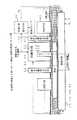
図2は、本発明の第一ないし第三の実施形態を示す図である。
図において、図6に示すものと機能および構成が同じものについては、同じ符号を付与して示し、ここではその説明を省略する。
本実施形態と図6に示す従来例との構成の相違点は、センサ72-6とローラ73-aとで挟まれた搬送路70の区間の内、印字ヘッド75Aと対向する領域よりローラ73-aに近い箇所にセンサ61が付加され、プロセッサ76に代えてプロセッサ62が備えられ、そのセンサ61の出力がプロセッサ62の対応する入力ポートに接続された点にある。
【0035】
なお、本実施形態と図1に示すブロック図との対応関係については、搬送路70は搬送路10に対応しプリンタユニット75およびプロセッサ62は印刷手段11,31に対応し、印字ヘッド75Aは印字ヘッド11A,31Aに対応し、センサ61およびプロセッサ62は媒体位置検出手段12,21,32,72-6に対応し、ローラ73-A〜73-F、73-a、73-bおよびプロセッサ62は搬送手段13,22,34,41に対応し、プロセッサ62は空行検出手段33に対応する。
【0036】
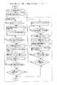
図3は、本発明の第一ないし第三の実施形態の動作を説明する図である。
図4は、本発明の第一および第二の実施形態の動作フローチャートである。
以下、図2〜図4および図8を参照して本発明の第一の実施形態の動作を説明する。
【0037】
プロセッサ62は、従来例と同様の手順に基づいて印刷処理を行い(図8(1) 〜(5))、その印刷処理の過程では、印刷されるべき頁にある全ての行について印刷が完了し、後続する頁に対して印刷されるべき情報がある場合には、プリンタユニット75の駆動を停止し(図4(1))、かつ自動頁捲り機構74を駆動する(図4(2))。さらに、プロセッサ62は、図8(10)、(11)に示す手順で示される処理に代えて、以下の印刷続行処理を行う(図4(3))。
【0038】
印刷続行処理の過程では、プロセッサ62は、自動頁捲り機構74と所定のハンドシェークを行うことによって、改頁が完了するまで待機し(図4(a))、かつセンサ72-7を介してその通帳が搬送路70に残留していることを確認する(図4(b))。
さらに、プロセッサ62は、ローラ73-D、73-a、73-b、73-Eを駆動することによってセンサ72-7の方向に通帳を搬送し(図3(1)、図4(c))、かつセンサ61を介して「そのセンサ61の位置にその通帳の下端が到達した(図3(2))こと」を検出する(図4(d))と、これらのローラ73-D、73-a、73-b、73-Eの駆動を一端取り止める(図4(e))。
【0039】
また、プロセッサ62は、後続して印刷されるべき行の数kを印刷されるべき情報の情報量および形式に基づいて算出する(図4(f))。
また、プロセッサ62は、通帳の下端と最下行との距離db と、搬送路70上におけるセンサ61と印字ヘッド75Aとの距離DSH、その通帳の頁における行の間隔Δとに対して、
S∝Δ(24−k)+db+DSH
で示されるステップ数Sに亘ってローラ74-E、73-b、73-a、73-Dを適宜駆動することによって、この通帳を挿入口71の方向に搬送し(図3(3)、図4(g))、かつプリンタユニット75を駆動する(図4(h))ことによって、その通帳の最終行(第24行)から行番号の降順に印刷を行う。
【0040】
なお、プロセッサ62がこの印刷の過程で行う処理については、ローラ74-E、73-b、73-a、73-Dが駆動される順序および方向が反対であり、かつ印刷の対象となる行の行番号が降順となる点を除いて従来例と同じであるので、ここでは、その詳細な説明を省略する。
さらに、プロセッサ62は、このような印刷の過程では、センサ72-6を介してそのセンサ72-6の位置に通帳の上端が到達し、かつ記帳されるべき情報が残っていることを識別すると、ローラ73-E、73-b、73-a、73-Dを逆方向に駆動することによって、通帳をセンサ72-7の方向に搬送する(図4(i))と共に、センサ72-6を介してそのセンサ72-6の位置に通帳の下端が到達したことを検出した時点で、これらのローラ73-E、73-b、73-a、73-Dの駆動を取り止める(図4(j))。
【0041】
また、プロセッサ62は、従来例と同様にして、プリンタユニット75の駆動を停止した(図4(k))後に、自動頁捲り機構74を駆動し(図4(m))、その自動頁捲り機構74によって印刷の対象となったさらに後続する頁については、従来例と同様にして行番号の昇順に印刷処理を行う(図4(n))。
すなわち、搬送路70に沿って印字ヘッド75Aの近傍で通帳が双方向に交互に搬送されることによってその通帳の複数頁に亘る印刷が行われ、かつ行番号の降順に行われるべき印刷が開始される際には、上式で示されるステップ数Sに亘ってローラ74-E、73-b、73-a、73-Dが駆動されることによって、通帳が挿入口71の方向に過送りされる。
【0042】
したがって、本実施形態によれば、ローラ74-E、73-b、73-a、73-Dに固有のバックラッシュが一定の方向に集約されることによって記帳の品質が高く維持され、かつ印刷の対象となる頁が更新される度に通帳がホームポジションに搬送される従来例に比べて印刷の効率が高められる。
なお、本実施形態では、挿入口71から挿入された通帳の頁と、その頁に後続する偶数番目の頁との双方について、印刷の開始に先行する位置合わせがセンサ72-6を介して行われている。
【0043】
しかし、このような位置合わせについては、センサ61を介して通帳の上端が検出された時点、あるいはその時点以降にローラ74-E、73-b、73-a、73-Dが駆動されたステップの総数が所定の値に達した時点を基準として行われてもよい。
また、本実施形態では、上述した過送りが行われることによってローラ74-E、73-b、73-a、73-Dに固有のバックラッシュが一定の方向に集約されているが、このようなバックラッシュが許容される場合には、通帳に印刷されるべき帳票としての形式(既述の距離db を含む。)と、印字ヘッド75Aとセンサ61との間の距離DSHとは、如何なるものであってもよい。
【0044】
以下、本発明の第二の実施形態について説明する。
本実施形態と上述した第一の実施形態との構成の相違点は、図3(a) に示すように、印字ヘッド75Aとセンサ61との間の距離DSHと、通帳の上端とその通帳の先頭行との間の距離dt とに対して、
DSH≦dt
の不等式が成立する位置にそのセンサ61が配置され、搬送路70に沿ってこのセンサ61の位置から挿入口71の方向に通帳の全長dに亘って隔たった位置にセンサ72-6が配置され、図2に点線で示すように、搬送路70の内、センサ61、72-6で挟まれた区間とその区間の近傍とに自動頁捲り機構74が周設された点にある。
【0045】
以下、図3〜図4を参照して本発明の第二の実施形態の動作を説明する。
本実施形態の特徴は、行番号の降順に印刷された頁に後続する頁の印刷の開始に先行して、ローラ73-E、73-b、73-a、73-Dが逆方向に駆動される時点にある。
【0046】
プロセッサ62は、通帳が挿入口71の方向に搬送され、かつ行番号の降順に印刷が行われている期間には、図4に点線で示すように、「センサ72-6の位置に通帳の上端が到達したこと」は識別しない。
しかし、プロセッサ62は、「センサ72-6の位置に通帳の下端が到達したこと(あるいは、センサ61の位置に通帳の上端が到達したこと)」を識別すると、まず、ローラ73-E、73-b、73-a、73-Dの駆動を取り止め(図4(j))、かつプリンタユニット75の駆動を停止する(図4(k))と共に、自動頁捲り機構74を駆動する(図4(m))。
【0047】
さらに、プロセッサ62は、ローラ73-E、73-b、73-a、73-Dを逆方向に駆動することによって、挿入口71と反対の方向に通帳を搬送すると共に、従来例と同様にして行番号の昇順に印刷処理を行う(図4(n))。
このように本実施形態によれば、印字ヘッド75Aとセンサ61との間の距離DSHが通帳の上端とその通帳の先頭行との間の距離dt 以下の値に設定され、この通帳が印刷処理の過程で双方向に搬送されるべき搬送路71の区間のほぼ中央部において自動頁捲り機構74によって改頁が行われるので、このような距離DSHが何ら規定されず、かつ改頁に先行して通帳の搬送が無用に行われる既述の第一の実施形態に比べて印刷の効率が高められる。
【0048】
また、本実施形態では、印字ヘッド75Aとセンサ61との間の距離DSHが通帳の上端とその通帳の先頭行との間の距離dt に等しい値に設定された場合には、この先頭行の位置併せては通帳の搬送が何ら行われることなく完了する。
したがって、既述のバックラッシュが許容される限り、印刷の効率がさらに高められる。
【0049】
以下、本発明の第三の実施形態について説明する。
本実施形態と上述した第二の実施形態との構成の相違点は、図3(b) に示すように、印字ヘッド75Aとセンサ61との間の距離DSHと、通帳の全長d、その通帳の上端と先頭行との間の距離dt と、この通帳の下端と最下行との間の距離db とに対して、
dt<DSH<(d−db)
の不等式が成立する位置にそのセンサ61が配置され、搬送路70に沿ってこのセンサ61の位置から挿入口71の方向に通帳の全長d隔たった位置にセンサ72-6が配置された点にある。
【0050】
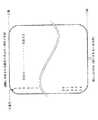
図5は、本発明の第三の実施形態の動作フローチャートである。
以下、図3〜図5を参照して本発明の第三の実施形態の動作を説明する。
本実施形態の特徴は、後続する頁に印刷が行われる順序と、その印刷が行われるために、通帳がローラ74-E、73-b、73-a、73-Dを介して搬送される距離と方向とにある。
【0051】
プロセッサ62は、通帳に行番号の昇順と降順との何れで印刷が行われている場合においても、該当する頁について印刷が完了し、かつ後続する頁に印刷されるべき何らかの情報がある場合には、ローラ74-E、73-b、73-a、73-Dを駆動することによって、「センサ72-6の位置に通帳の下端が到達する(あるいは、センサ61の位置に通帳の上端が到達する)」方向に、その通帳を搬送する(図5(1))。
【0052】
さらに、プロセッサ62は、「センサ72-6の位置に通帳の下端が到達した(あるいは、センサ61の位置に通帳の上端が到達した)こと」を認識すると、自動頁捲り機構74を駆動する(図5(2))。
【0053】
また、プロセッサ62は、通帳の面の内、このような状態で上述したセンサ61、72-6の配置の下で印字ヘッド65Aに対向する行の番号L(整数でなくてもよい。)と、その通帳に印刷される過程でこの通帳が搬送される際に、ローラ74-E、73-b、73-a、73-Dが駆動されるべきステップの総数nとが予め与えられる。
【0054】
さらに、プロセッサ62は、このような状態において後続して印刷されるべき情報の情報量および形式に基づいて、これらの情報の全てが印刷される行の総数Mを求め(図5(3))、
M≦L
の不等式が成立するか否かの判別を行う(図5(4))。
【0055】
プロセッサ62は、その判別の結果が真である場合には、
S0 =n(L−M)
の式で与えられるステップ数S0 に亘ってローラ74-E、73-b、73-a、73-Dを駆動し、かつ通帳を挿入口71側に搬送した時点でこれらのローラ74-E、73-b、73-a、73-Dの駆動を取り止めることによって、該当する頁について印刷が最先に開始されるべき行が印字ヘッド75Aに対向する位置(以下、「疑似ポームポジション」という。)を確定する(図5(5))。
【0056】
しかし、上述した判別の結果が偽である場合には、プロセッサ62は、
M<24
の不等式が成立するか否かの判別を行う(図5(6))。
また、プロセッサ62は、その判別の結果が真である場合には、
S1 =n(M−L) ・・・(1)
の式で与えられるステップ数S1 に亘ってローラ74-E、73-b、73-a、73-Dを駆動し、かつ通帳を挿入口71と反対の方向に搬送した時点でこれらのローラ74-E、73-b、73-a、73-Dの駆動を取り止めることによって、上述した疑似ポームポジションを確定する(図5(7))。
【0057】
しかし、この判別の結果が偽である場合には、プロセッサ62は、
S2 =n(24−L) ・・・(2)
の式で与えられるステップ数S2 に亘ってローラ74-E、73-b、73-a、73-Dを駆動し、かつ通帳を挿入口71と反対の方向に搬送した時点でこれらのローラ74-E、73-b、73-a、73-Dの駆動を取り止めることによって、疑似ポームポジションを確定する(図5(8))。
【0058】
さらに、プロセッサ62は、このようにして疑似ホームポジションが確定した後には、ローラ73-E、73-b、73-a、73-Dを逆方向に駆動することによって、通帳をセンサ72-7の方向に搬送する(図5(9))と共に、該当する頁について行番号の降順に印刷処理を行う(図5(10)) 。
すなわち、センサ72-6の位置に通帳の下端が到達した(あるいは、センサ61の位置に通帳の上端が到達した)状態で印字ヘッド65Aに対向する行は、その通帳の該当する頁の先頭行と末尾の行とで挟まれた何れかの行に予め設定される。
【0059】
したがって、本実施形態によれば、上述した疑似ホームポジションが確定されるために通帳が搬送されるべき距離の平均値は、既述の第一および第二の実施形態における値より平均的に小さな値となり、かつ印刷の効率が高められる。
なお、本実施形態では、行番号の降順のみに印刷が行われているが、例えば、既述の処理の手順によれば上式(1) に示されるステップ数S1 が適用されるべきであっても
L<M−L
が成立する場合と、上式(2) に示されるステップ数S2 が適用されるべきであっても
L<24−L
が成立する場合とには、それぞれ
S3=nL
の式で示されるステップ数S3 に亘ってローラ73-E、73-b、73-a、73-Dを逆の方向に駆動することによって、該当する頁の先頭行に疑似ホームポジションが設定され、かつ行番号の昇順に印刷が行われることによって、さらに、印刷の効率が高められてもよい。
【0060】
なお、上述した各実施形態では、センサ61より挿入口71側に印字ヘッド75Aが配置されているが、印刷処理の過程においてローラ73-E、73-b、73-a、73-Dがプロセッサ62の配下で的確に駆動されるならば、このセンサ61は印字ヘッド75Aより搬送路70の末端側に配置されてもよい。
さらに、上述した各実施形態では、自動頁捲り機構74が備えられ、かつ後続する頁に対して何らかの情報が印刷される場合に本発明が適用されているが、例えば、挿入口71から挿入された通帳に最先に印刷されるべき頁の下端がセンサ61によって検出され、その頁の印刷が行番号の降順に行われてもよい。
【0061】
また、上述した各実施形態では、自動頁捲り機構74の構成および動作が何ら示されていないが、搬送路70の所望の位置にある通帳について確実に改頁が行われるならば、このような自動頁捲り機構74の方式は如何なるものであってもよい。
さらに、上述した各実施形態では、単一の自動頁捲り機構74が搬送路70の所定の位置に配置されているが、通帳が搬送されるべき道程が短縮されることによって、従来例より印刷の効率が高められるならば、通帳と共にその搬送路70に沿って搬送され、あるいは印字ヘッド75Aの位置からこの搬送路70に沿って反対方向に所定の距離隔たった位置に個別に2つの自動頁捲り機構が備えられてもよい。
【0062】
また、上述した各実施形態では、プロセッサ62の配下で駆動されるローラ73-A〜73-F、73-a、73-bによって通帳が搬送路70に沿って搬送されているが、このような通帳の搬送については、所望の応答性、精度および信頼性が確保されるならば、例えば、ベルトその他の如何なる方式の動力伝達手段を介して行われてもよい。
【0063】
さらに、上述した各実施形態では、印刷の対象となるべき頁および行がプロセッサ62によって管理されているが、このような頁および行の管理については、例えば、プリンタユニット75によって行われ、あるいは記帳(印刷)されるべき情報をプロセッサ62に与えるホストプロセッサ(図示されない。)によって行われてもよく、如何なる形態の負荷分散や機能分散の下で行われてもよい。
【0064】
また、上述した各実施形態では、ローラ73-A〜73-F、73-a、73-bが駆動されるステップの数に応じて印刷されるべき行が検出されているが、このような行の検出は、例えば、行毎の濃度の分布が光学的に、あるいは電磁的に検出されることによって行われてもよい。
さらに、上述した各実施形態では、ローラ73-a、73-bが通帳の搬送のみに適用されているが、これらのローラ73-a、73-bは、自動頁捲り機構74によって改頁に共用されてもよい。
【0065】
また、上述した各実施形態では、綴じ白が行に並行な方向に形成され、かつほぼ中央部に位置する通帳に対してプリンタユニット75によって印刷が行われているが、本願発明は、このような通帳に限定されず、例えば、両面に印刷面を有するカード、綴じ白が上端、下端、左端および右端の何れかにある通帳その他の小冊子の記帳にも同様に適用可能である。
【0066】
さらに、本実施形態では、センサ61、72-6、72-7として光学センサが適用されているが、所望の確度および応答性で通帳の上端や下端が検出されるならば、機械的接点からなるセンサ、電磁的あるいは静電的なセンサその他の如何なるセンサが適用されてよい。
【0067】
【発明の効果】
上述したように本発明が適用された端末や情報処理系では、記帳が高い品質および応答性で効率的に実現され、かつ顧客に対するサービス品質が高められると共に、保守および運用にかかわるコストの削減および作業環境の改善に併せて、最繁時に適応するために設置されるべき機器の台数の大幅な削減が可能となる。
【0068】
また、本発明に関連する第一の発明では、従来例に比べて、印刷の開始に先行して媒体が搬送されるべき距離が短縮され、印刷の効率が高められると共に、その媒体の位置の偏差が確度高く圧縮される。
さらに、本発明に関連する第二および第四の発明では、位置合わせが行われた後に最先に印刷が行われるべき行と、印字ヘッドとの隔たりを圧縮するために媒体が搬送される距離が上述した第一の発明に比べて確度高く短縮される。
【0069】
また、本発明に関連する第三の発明では、最先に印刷されるべき行と、印字ヘッドとの隔たりを圧縮するために媒体が搬送されるべき距離は、確度高く短縮される。
【図面の簡単な説明】
【図1】本発明に関連した第一ないし第五の発明の原理ブロック図である。
【図2】本発明の第一ないし第三の実施形態を示す図である。
【図3】本発明の第一ないし第三の実施形態の動作を説明する図である。
【図4】本発明の第一および第二の実施形態の動作フローチャートである。
【図5】本発明の第三の実施形態の動作フローチャートである。
【図6】 従来の記帳装置の構成例を示す図である。
【図7】 通帳に印刷されるべき帳票の形式の一例を示す図である。
【図8】 従来例の動作フローチャートである。
【符号の説明】
10,70 搬送路
11,31 印刷手段
11A,31A,75A 印字ヘッド
12,21,32,72-6 媒体位置検出手段
13,22,34,41 搬送手段
33 印刷行数算出手段
61 センサ
62,76 プロセッサ
71 搬入口
72 センサ
73 ローラ
74 自動頁捲り機構
75 プリンタユニット[0001]
BACKGROUND OF THE INVENTION
The present invention relates to a bookkeeping apparatus that automatically prints desired information on a passbook or other booklet-like medium.
[0002]
[Prior art]
In recent years, banking systems and other financial information systems have been applied to advanced equipment such as CD (Cash Dispenser), AD (Automatic Depositor), ATM (Automatic Tellers Machine) by applying advanced information processing technology and telecommunications technology. In addition to the streamlining and labor saving of operations, the promotion of management efficiency and the expansion of services to customers are being pursued.
[0003]
Furthermore, among these automated equipment, for the bookkeeping device that automatically records various information indicating the contents and processes of transactions in the passbook etc., new financial products and customer needs are combined with performance and reliability. Flexible adaptability and expandability are required.
[0004]
FIG. 6 is a diagram showing a configuration example of a conventional bookkeeping apparatus.
In the figure, an insertion port 71 into which the passbook is to be inserted is formed at one end of a
[0005]
The outputs of the sensors 72-1 to 72-7 are connected to the corresponding input ports of the processor 76, and the automatic
In the bookkeeping apparatus having such a configuration, when the processor 76 detects that the bankbook to be booked is inserted into the
[0006]
The processor 76 detects the position where information is written in the magnetic stripe by reading the magnetic stripe attached to the passbook via the sensors 72-2 and 72-3 (FIG. 8 (2)). )) And confirms that the information is legitimate information (FIG. 8 (3)).
[0007]
Further, when the processor 76 confirms that the upper end of the bankbook has reached the position of the sensor 72-4 (hereinafter simply referred to as "home position") via the sensors 72-4 and 72-5, the processor 73-4 By appropriately driving C and 73-D, as shown in FIG. 7, among all the lines that can be printed in the passbook, an empty “first line” (here, for the sake of simplicity, the line number This passbook is conveyed to a position facing the
[0008]
It should be noted that the means for identifying a line other than the first line in this way when the line other than the first line is the above-mentioned “first line” is not related to the present invention and will not be described here.
Further, the processor 76 appropriately gives the printer unit 75 timing of printing, information to be printed, and the like, and drives the rollers 73-D, 73-a, 73-b, and 73-E to perform processing described later. The “printing process” including is performed (FIG. 8 (5)).
[0009]
On the other hand, the printer unit 75 sequentially prints the information given together with the timing on the corresponding row of the passbook via the
In the course of the printing process, the processor 76 determines whether or not the lower end of the passbook has reached the position of the sensor 72-6 (meaning that the last line of the passbook has been printed). The total number of steps in which the pulse motors constituting the rollers 73-C, 73-D, 73-a, 73-b, and 73-E are driven over a period in which the determination result is false. Is accumulated.
[0010]
Further, when the processor 76 identifies that the lower end of the passbook has reached the position of the sensor 72-6, it determines whether or not printing of all information to be recorded has been completed, and the determination result is true. In some cases, the drive of the printer unit 75 is stopped (FIG. 8 (6)), and the rollers 73-E, 73-b, 73-a, 73-D, 73-C, 73-B, 73-A Are sequentially driven in the reverse direction to discharge the passbook out of the insertion slot 71 (FIG. 8 (7)).
[0011]
However, if the determination result described above is false, the processor 76 stops driving the printer unit 75 (FIG. 8 (8)) and drives the automatic page turning mechanism 74 (FIG. 8 (8)). ).
The automatic
[0012]
Note that the mechanism for accomplishing this page break and the operation of the mechanism are not related to the present invention, and the description thereof is omitted here.
Further, the processor 76 sequentially drives the rollers 73-E, 73-b, 73-a, 73-D, 73-C, 73-B, and 73-A in the reverse direction to move toward the insertion port 71. The bankbook is transported (FIG. 8 (10)).
[0013]
During the period in which the bankbook is conveyed in this manner, the processor 76 monitors the position of the bankbook via the sensor 72-4, and when detecting that the bankbook has reached the “home position” described above, the roller 73 -E, 73-b, 73-a, 73-D, 73-C, 73-B, 73-A are stopped (FIG. 8 (11)) and the processing described above is performed for the subsequent pages of the passbook (FIG. 8 (4)-(11)) is repeated suitably.
[0014]
The sensors 72-4 to 72-7 are used to detect the skew, upper end, lower end, and remaining of the passbook under the processor 76. For details of operations and processes related to such detection, Since it is not related to the present invention, its description is omitted here.
[0015]
[Problems to be solved by the invention]
By the way, in the above-described conventional example, in order to print over a plurality of pages, the passbook is transported to the home position after the page break is performed, and further, “the first line faces the
[0016]
Therefore, the time required for bookkeeping is unnecessarily long, and responsiveness is not always sufficient, and bookkeeping operations concentrated in the most frequent time zone are automatically performed within the standby time range that the customer can tolerate. There was a high possibility that the number of units to be installed increased and unnecessary power was consumed.
An object of the present invention is to provide a bookkeeping apparatus in which the responsiveness is greatly improved without the structure being changed significantly.
[0017]
[Means for Solving the Problems]
In the first aspect of the invention, the medium is booked by printing line by line on the medium on the conveyance path provided for conveyance of the medium inserted from the insertion slot, and subsequent pages of the medium are recorded. In the bookkeeping apparatus that prints on the subsequent page of the medium after the page turning of the medium is performed, the transporting means follows the transport path after the page turning is completed. By conveying the medium in the direction of the insertion slot, the last line to be printed on the subsequent page is aligned with the position of the print head used for printing, and for each line with respect to the subsequent page. The direction of the insertion slot along the transport path every time printing is completedInThe medium is conveyed line by line.
According to a second aspect of the present invention, in the bookkeeping apparatus according to the first aspect, the print line number calculating means should print on the subsequent page based on the amount of information to be booked and the size of the medium. Number of rows MP Ask for. The conveying means is located on the conveying path where the top line of the medium is separated from the print head in a state where the upper end of the medium is located at a position separated from the print head along the conveying path in the direction of the insertion port by the full length of the medium Distance DL And the line spacing Δ on the medium and the number M of lines obtained by the printed line number calculating meansP The direction of the inlet of the medium over a distance equal to the difference between the product andOpposite directionTransport to.
FIG. 1 is a principle block diagram of the first to fifth inventions related to the present invention.
A first invention related to the present invention is a printing method for printing on a medium that is fed through the conveyance path 10 that conveys a medium inserted from an insertion port and the medium that is given through the conveyance path 10 and that records the medium. Means 11 and a printing apparatus for printing on the medium by the printing means 11 and, when there is information to be printed for a subsequent page, turning the medium and printing on the medium again The printing means 11 has a print head 11A sandwiched between the print head 11A and the conveyance path 10 at a distance equal to or less than the full length of the medium, and a front end side with respect to the medium conveyance direction. A plurality of medium position detecting means 12 and 72-6 for detecting a state in which the end portion is located, and a leading end with respect to the medium transport direction in which the state is detected by the respective medium position detecting means 12 and 72-6. Side and The conveying unit 13 conveys the medium in a direction passing under the print head along the conveying path 10, and the medium conveyed by the conveying unit 13 by the
[0018]
Second related to the present inventionThe invention includes: a conveyance path 10 that conveys a medium inserted from an insertion port; a
[0019]
Third related to the present inventionThe invention ofAccording to the first invention related to the present inventionIn the bookkeeping apparatus, the number M of lines to be printed on the corresponding page of the medium by the printing means 31 based on the information amount of the information to be booked and the size of the medium.P The print line number calculating means 33 for calculating the distance D from the earliest line to the position where the print head 31A is opposed to the medium located at the location D.L Is given in advance and its distance DL And the interval Δ between these lines and the number M of lines obtained by the print line number calculating means 33.P When the former exceeds the latter over a distance equal to the absolute value of the difference between the print head and the product, the distance between the print head 31A and the nearest edge decreases, and vice versa. The medium whose state has been detected by the one medium position detecting means 32, 72-6 is transported along the transport path 10 in the direction in which the one medium position detecting means 32, 72-6 The distance between the end on the leading end side in the conveyance direction of the medium in which the state is to be detected by 72-6 and all the rows formed on the medium exceeds the minimum distance, and the maximum It is less than a distance.
[0020]
Fourth related to the present inventionThe invention includes: a conveyance path 10 that conveys a medium inserted from an insertion port; a
[0022]
First related to the present inventionIn the bookkeeping apparatus according to the invention, the medium position detecting means 12 and 72-6 are separated from the print head 11A along the conveyance path 10 over a distance equal to or less than the total length of the medium given through the conveyance path 10. A state is detected in which the end portion on the leading end side is located at the position with respect to the conveyance direction of the medium. The conveying means 13 is in such a direction that the end, which is the leading end side with respect to the medium conveying direction detected by the medium position detecting means 12, 72-b, passes under the print head 11A along the conveying path 10. , Transport the medium. The
[0023]
That is, for a medium that is to be printed in units of rows under the linkage of the transport unit 13 and the
Therefore, compared with the conventional example in which such alignment is performed in the vicinity of the opening portion of the conveyance path 10 provided without any relative distance to the print head 11A being defined, prior to the start of printing. The distance that the medium should be transported is accurately shortened, the printing efficiency is increased, and the positional deviation of the medium is compressed.
[0024]
Second related to the present inventionIn the bookkeeping apparatus according to the present invention, the medium position detecting means 21 and 72-6 are arranged in the vicinity of the medium fed through the conveyance path 10 at a position separated from the print head 11A along the conveyance path 10 by a specific distance. The state in which the end of is located is detected. The conveying
[0025]
By the way, the specific distance described above is the distance between the nearest edge of the medium whose state described above is to be detected by the medium position detecting means 21 and 72-6 and all the rows formed on the medium. Is less than the minimum distance.
Therefore, the medium is conveyed by the conveying means 22 in order to compress the distance between the
[0026]
Third related to the present inventionIn the bookkeeping apparatus according to the invention, the printed line number calculating means 33 is based on the information amount of information to be booked and the size of the medium given through the transport path 10 and the corresponding page of the medium. Number of lines to be printed onP Ask for.
Further, the medium position detecting means 32, 72-6 has a state in which the end portion on the leading end side is located at a specific distance from the print head 31A along the conveyance path 10 with respect to the conveyance direction of the medium. To detect.
[0027]
The transport unit 34 has a distance D from the earliest line to the position where the print head 31A is opposed to the medium in which such a state is detected.L Is given in advance. Further, the conveying means 34 has a distance DL And the line spacing Δ and the number M of lines obtained by the printed line number calculating means 33.P If the former exceeds the latter over a distance equal to the absolute value of the difference between the print header 31A and the previously describedIt is on the tip side with respect to the transport directionThe medium in which the above-described state is detected by the medium position detection unit 32 is transported along the transport path 10 in a direction in which the distance from the end portion decreases, or in a direction in which the distance from the end increases. The printing means 31 prints information to be booked in units of rows formed in the direction intersecting the transport path 10 on the medium transported in this way.
[0028]
YouIn other words, at the time when the alignment performed prior to the start of printing is completed, the print head 31A is placed in one of the areas where any information to be booked can be printed among the pages of the corresponding medium. Since they face each other, the distance to which the medium is to be transported by the transport means 34 in order to compress the distance between the line to be printed first and the
[0029]
Fourth related to the present inventionIn the bookkeeping apparatus according to the present invention, the medium position detection means 21 and 72-6 convey the medium supplied via the conveyance path 10 to a location separated from the print head 11A along the conveyance path 10 by a specific distance. A state in which the end portion on the tip side with respect to the direction is located is detected. The conveying means 41 is arranged in such a direction that the relative distance between the end of the leading end side and the
[0030]
By the way, the above-mentioned specific distance is equal to the end portion on the leading end side with respect to the conveyance direction of the medium to be detected by the medium position detecting means 21 and 72-6, and all the states formed on the medium. The maximum distance is exceeded in the distance to the line.
Accordingly, the medium is conveyed by the conveying means 41 in order to compress the distance between the
[0033]
DETAILED DESCRIPTION OF THE INVENTION
Hereinafter, embodiments of the present invention will be described in detail with reference to the drawings.
[0034]
FIG.First to third of the present inventionIt is a figure which shows embodiment.
In the figure, components having the same functions and configurations as those shown in FIG. 6 are given the same reference numerals, and description thereof is omitted here.
The difference between the present embodiment and the conventional example shown in FIG. 6 is that the
[0035]
As for the correspondence relationship between the present embodiment and the block diagram shown in FIG. 1, the
[0036]
FIG.First to third of the present inventionIt is a figure explaining operation | movement of embodiment.
FIG.First and second of the present inventionIt is an operation | movement flowchart of embodiment.
Hereinafter, referring to FIG. 2 to FIG. 4 and FIG.The first of the present inventionThe operation of the embodiment will be described.
[0037]
The processor 62 performs print processing based on the same procedure as in the conventional example (FIGS. 8 (1) to (5)), and in the course of the print processing, printing is completed for all lines on the page to be printed. If there is information to be printed on subsequent pages, the printer unit 75 is stopped (FIG. 4 (1)) and the automatic
[0038]
In the process of the print continuation process, the processor 62 performs a predetermined handshake with the automatic
Furthermore, the processor 62 drives the rollers 73-D, 73-a, 73-b, and 73-E to convey the bankbook in the direction of the sensor 72-7 (FIG. 3 (1), FIG. 4 (c)). ), And detecting that the lower end of the passbook has reached the position of the sensor 61 (FIG. 3 (2)) (FIG. 4D), these rollers 73-D, The drive of 73-a, 73-b, 73-E is stopped once (FIG. 4 (e)).
[0039]
Further, the processor 62 calculates the number k of lines to be subsequently printed based on the information amount and format of the information to be printed (FIG. 4 (f)).
The processor 62 also determines the distance d between the lower end of the passbook and the bottom row.b And the distance D between the sensor 61 and the
S∝Δ (24−k) + db+ DSH
By appropriately driving the rollers 74-E, 73-b, 73-a, 73-D over the number of steps S shown in FIG. 3, the passbook is conveyed in the direction of the insertion slot 71 (FIG. 3 (3), 4 (g)) and by driving the printer unit 75 (FIG. 4 (h)), printing is performed in the descending order of the line numbers from the last line (the 24th line) of the passbook.
[0040]
Regarding the processing performed by the processor 62 in the course of printing, the order and direction in which the rollers 74-E, 73-b, 73-a, and 73-D are driven are opposite, and the lines to be printed Since the line numbers are the same as those in the conventional example except that the line numbers are in descending order, detailed description thereof is omitted here.
Furthermore, when the processor 62 identifies that the upper end of the bankbook has reached the position of the sensor 72-6 via the sensor 72-6 and information to be recorded remains in the process of such printing. The rollers 73-E, 73-b, 73-a and 73-D are driven in the opposite direction to convey the bankbook in the direction of the sensor 72-7 (FIG. 4 (i)) and the sensor 72-6. When it is detected that the lower end of the passbook has reached the position of the sensor 72-6, the driving of these rollers 73-E, 73-b, 73-a, 73-D is stopped (FIG. 4 ( j)).
[0041]
Similarly to the conventional example, the processor 62 stops driving the printer unit 75 (FIG. 4 (k)), and then drives the automatic page turning mechanism 74 (FIG. 4 (m)). For the subsequent pages that have been printed by the
That is, the passbook is alternately conveyed in the vicinity of the
[0042]
Therefore, according to the present embodiment, the backlash inherent to the rollers 74-E, 73-b, 73-a, and 73-D is concentrated in a certain direction, so that the quality of the book can be maintained high and printing can be performed. As compared with the conventional example in which the passbook is transported to the home position each time the target page is updated, the printing efficiency is increased.
In the present embodiment, the positions preceding the start of printing for both the passbook page inserted from the insertion slot 71 and the even-numbered pages following the page.TogetherIs performed via the sensor 72-6.
[0043]
However, for such alignment, the step in which the rollers 74-E, 73-b, 73-a, and 73-D are driven when the upper end of the bankbook is detected via the sensor 61 or after that time is detected. It may be performed on the basis of the time when the total number of reaches a predetermined value.
In this embodiment, backlash inherent to the rollers 74-E, 73-b, 73-a, and 73-D is concentrated in a certain direction due to the above-described overfeed. If backlash is allowed, the form as a form to be printed on the passbook (the distance d described above)b including. ) And the distance D between the
[0044]
Less than,Second of the present inventionEmbodiments will be described.
This embodiment andFirst mentioned aboveThe difference from the embodiment is that the distance D between the
DSH≦ dt
The sensor 61 is disposed at a position where the above inequality is established, and a sensor 72-6 is disposed along the
[0045]
Hereinafter, referring to FIGS.Second of the present inventionThe operation of the embodiment will be described.
The feature of the present embodiment is that the rollers 73-E, 73-b, 73-a, and 73-D are driven in the reverse direction prior to the start of printing of the pages following the pages printed in descending order of the row numbers. Is at the point.
[0046]
During the period when the bankbook is conveyed in the direction of the insertion slot 71 and printing is performed in the descending order of the row numbers, the processor 62 “passes the bankbook at the position of the sensor 72-6 as shown by the dotted line in FIG. It does not identify that the upper end has been reached.
However, when the processor 62 identifies “the lower end of the passbook has reached the position of the sensor 72-6 (or the upper end of the passbook has reached the position of the sensor 61)”, first, the rollers 73-E and 73 are detected. -b, 73-a, 73-D are stopped (FIG. 4 (j)), and the printer unit 75 is stopped (FIG. 4 (k)), and the automatic
[0047]
Further, the processor 62 drives the rollers 73-E, 73-b, 73-a, and 73-D in the reverse direction, thereby conveying the bankbook in the direction opposite to the insertion slot 71 and in the same manner as in the conventional example. The printing process is performed in ascending order of the line numbers (FIG. 4 (n)).
Thus, according to the present embodiment, the distance D between the
[0048]
In the present embodiment, the distance D between the print head 75 </ b> A and the sensor 61.SHIs the distance d between the top of the passbook and the first line of the passbookt When the value is set equal to, the transfer of the passbook is completed at the same time as the position of the first row.
Therefore, as long as the above-described backlash is allowed, the printing efficiency is further increased.
[0049]
Less than,Third of the present inventionEmbodiments will be described.
This embodiment andSecond mentioned aboveThe difference from the embodiment is that the distance D between the
dt<DSH<(Ddb)
The sensor 61 is arranged at a position where the inequality is established, and the sensor 72-6 is arranged along the
[0050]
FIG.Third of the present inventionIt is an operation | movement flowchart of embodiment.
Hereinafter, referring to FIGS.Third of the present inventionThe operation of the embodiment will be described.
The feature of this embodiment is the order in which printing is performed on subsequent pages, and the passbook is conveyed via rollers 74-E, 73-b, 73-a, and 73-D in order to perform the printing. In distance and direction.
[0051]
The processor 62 completes printing for the corresponding page and has some information to be printed on the subsequent page, regardless of whether the passbook is printed in ascending order or descending order of the line numbers. By driving the rollers 74-E, 73-b, 73-a, 73-D, “the lower end of the passbook reaches the position of the sensor 72-6 (or the upper end of the passbook is The passbook is conveyed in the direction of “arriving” (FIG. 5 (1)).
[0052]
Further, when the processor 62 recognizes that “the lower end of the passbook has reached the position of the sensor 72-6 (or the upper end of the passbook has reached the position of the sensor 61)”, the processor 62 drives the automatic page turning mechanism 74 ( Fig. 5 (2)).
[0053]
Further, the processor 62, in the state of the bankbook, in this state, the line number L (not necessarily an integer) facing the print head 65A under the arrangement of the sensors 61 and 72-6 described above. When the bankbook is transported in the process of printing on the bankbook, the total number n of steps at which the rollers 74-E, 73-b, 73-a, and 73-D are to be driven is given in advance.
[0054]
Further, the processor 62 obtains the total number M of lines on which all of the information is printed based on the information amount and the format of information to be subsequently printed in such a state (FIG. 5 (3)). ,
M ≦ L
It is determined whether or not the inequality is established (FIG. 5 (4)).
[0055]
If the result of the determination is true, the processor 62
S0 = n (LM)
When the rollers 74-E, 73-b, 73-a, 73-D are driven over the number of steps S0 given by the following equation and the passbook is conveyed to the insertion port 71 side, these rollers 74-E, By stopping the driving of 73-b, 73-a, and 73-D, a position where printing should start first for the corresponding page faces the
[0056]
However, if the determination result described above is false, the processor 62
M <24
It is determined whether or not the inequality is established (FIG. 5 (6)).
Further, when the result of the determination is true, the processor 62
S1 = n (ML) (1)
These
[0057]
However, if the result of this determination is false, the processor 62
S2 = n (24-L) (2)
These
[0058]
Further, after the pseudo home position is determined in this way, the processor 62 drives the rollers 73-E, 73-b, 73-a, 73-D in the reverse direction, thereby detecting the bankbook as a sensor 72-7. (FIG. 5 (9)) and the corresponding pages are printed in descending order of line numbers (FIG. 5 (10)).
That is, the line facing the print head 65A in a state where the lower end of the passbook has reached the position of the sensor 72-6 (or the upper end of the passbook has reached the position of the sensor 61) is the first line of the corresponding page of the passbook. And a line between the last line and the last line.
[0059]
Therefore, according to the present embodiment, the average value of the distance to which the bankbook should be transported in order to determine the above-described pseudo home position isThe first and second mentionedThe average value is smaller than the value in the embodiment, and the printing efficiency is improved.
In this embodiment, printing is performed only in descending order of the line numbers. For example, according to the processing procedure described above, the number of steps S1 represented by the above equation (1) should be applied. Even
L <ML
Even if the number of steps S2 shown in the above equation (2) should be applied.
L <24-L
If
S3 = nL
By driving the rollers 73-E, 73-b, 73-a, 73-D in the reverse direction over the number of steps S3 shown in the equation, a pseudo home position is set in the first line of the corresponding page. In addition, the printing efficiency may be further improved by performing the printing in ascending order of the line numbers.
[0060]
In each of the embodiments described above, the
Further, in each of the above-described embodiments, when the automatic
[0061]
Further, in each of the above-described embodiments, the configuration and operation of the automatic
Further, in each of the above-described embodiments, the single automatic
[0062]
In the above-described embodiments, the passbook is conveyed along the
[0063]
Further, in each of the above-described embodiments, pages and lines to be printed are managed by the processor 62. Such page and line management is performed by, for example, the printer unit 75 or bookkeeping. It may be performed by a host processor (not shown) that supplies the information to be printed to the processor 62, and may be performed under any form of load distribution or function distribution.
[0064]
In each of the above-described embodiments, lines to be printed are detected according to the number of steps in which the rollers 73-A to 73-F, 73-a, and 73-b are driven. The detection of the row may be performed, for example, by optically or electromagnetically detecting the density distribution for each row.
Further, in each of the above-described embodiments, the rollers 73-a and 73-b are applied only to the transfer of the passbook. It may be shared.
[0065]
Further, in each of the above-described embodiments, the binding white is formed in a direction parallel to the row and printing is performed by the printer unit 75 on the passbook located substantially in the center. The present invention is not limited to such a passbook, and can be similarly applied to, for example, a book having a printing surface on both sides, a passbook or other booklet book in which binding white is located at any of the upper end, lower end, left end, and right end.
[0066]
Furthermore, in this embodiment, optical sensors are applied as the sensors 61, 72-6, 72-7. However, if the upper and lower ends of the passbook are detected with desired accuracy and responsiveness, the mechanical contacts can be used. A sensor, an electromagnetic or electrostatic sensor, or any other sensor may be applied.
[0067]
【The invention's effect】
As mentioned aboveIn terminals and information processing systems to which the present invention is applied, bookkeeping is efficiently realized with high quality and responsiveness, service quality for customers is improved, maintenance and operation costs are reduced, and work environment is improved. At the same time, the number of devices to be installed to adapt to the most busy time can be greatly reduced.
[0068]
Further, in the first invention related to the present invention, compared to the conventional example, the distance that the medium should be conveyed prior to the start of printing is shortened, the printing efficiency is increased, and the position of the medium is also increased. Deviation is compressed with high accuracy.
Further, in the second and fourth inventions related to the present invention, the distance that the medium is conveyed to compress the distance between the print head and the line to be printed first after the alignment is performed. Is shortened with higher accuracy than the first invention described above.
[0069]
In the third invention related to the present invention, the distance that the medium should be transported to compress the distance between the line to be printed first and the print head is shortened with high accuracy.
[Brief description of the drawings]
[Figure 1]First to fifth related to the present inventionIt is a principle block diagram of this invention.
[Figure 2]First to third of the present inventionIt is a figure which shows embodiment.
[Fig. 3]First to third of the present inventionIt is a figure explaining operation | movement of embodiment.
[Fig. 4]First and second of the present inventionIt is an operation | movement flowchart of embodiment.
[Figure 5]Third of the present inventionIt is an operation | movement flowchart of embodiment.
FIG. 6 is a diagram showing a configuration example of a conventional bookkeeping apparatus.
FIG. 7 is a diagram illustrating an example of a form format to be printed on a passbook.
FIG. 8 is an operation flowchart of a conventional example.
[Explanation of symbols]
10,70 transport path
11, 31 printing means
11A, 31A, 75A Print head
12, 21, 32, 72-6 Medium position detection means
13, 22, 34, 41 Conveying means
33 Print line number calculation means
61 sensors
62,76 processor
71 Carriage entrance
72 sensors
73 Laura
74 Automatic page turning mechanism
75 Printer unit
Claims (2)
Translated fromJapanese前記頁捲りの完了後に前記搬送路に沿って前記挿入口の方向に前記媒体を搬送することによって、前記印字に供される印字ヘッドの位置に対して、前記後続する頁における印字の対象となる末尾の行を位置合わせし、かつ前記後続する頁に対する行毎の印字が完了する度に前記搬送路に沿って前記挿入口の方向に前記媒体を行単位に搬送する搬送手段を備えた
ことを特徴とする記帳装置。Information to be printed on the subsequent pages of the medium by recording the medium by printing line by line on the medium on a conveyance path provided for conveyance of the medium inserted from the insertion slot. If there is, in the bookkeeping device that performs printing on the subsequent page of the medium after the page is turned,
By transporting the medium in the direction of the insertion port along the transport path after completion of the page turning, the position of the print head used for the printing becomes a target of printing on the subsequent page. A conveying unit that aligns the last line and conveys the medium line by line in the directionof the insertion port along the conveying path every time printing for each line on the subsequent page is completed. Characteristic bookkeeping device.
前記記帳が行われるべき情報の情報量と前記媒体のサイズとに基づいて前記後続する頁に印刷されるべき行の数MP を求める印刷行数算出手段を備え、
前記搬送手段は、
前記印字ヘッドから前記搬送路に沿って前記挿入口の方向に前記媒体の全長以上隔たった箇所に前記媒体の上端が位置する状態で、前記印字ヘッドに対して前記媒体の先頭の行が隔たった前記搬送路上の距離DL と、前記媒体における行の間隔Δと前記印刷行数算出手段によって求められた行の数MP との積との差に等しい距離に亘って、前記媒体を前記搬入口の方向と反対の方向に搬送する
ことを特徴とする記帳装置。The bookkeeping apparatus according to claim 1,
Printing line number calculating means for obtaining the number MP of lines to be printed on the subsequent page based on the amount of information to be booked and the size of the medium;
The conveying means is
The top row of the medium is separated from the print head in a state where the upper end of the medium is located at a position separated from the print head along the transport path in the direction of the insertion port by the full length of the medium. wherein a distance DL of the conveying path, over a difference in the distance equal to the product of the number MP of rows determined by the row spacing Δ between the printed number of rows calculating means in the medium, the carry said medium A bookkeeping device that conveys in adirection opposite to the mouth direction.
Priority Applications (1)
| Application Number | Priority Date | Filing Date | Title |
|---|---|---|---|
| JP23698098AJP3650273B2 (en) | 1998-08-24 | 1998-08-24 | Bookkeeping device |
Applications Claiming Priority (1)
| Application Number | Priority Date | Filing Date | Title |
|---|---|---|---|
| JP23698098AJP3650273B2 (en) | 1998-08-24 | 1998-08-24 | Bookkeeping device |
Publications (2)
| Publication Number | Publication Date |
|---|---|
| JP2000062267A JP2000062267A (en) | 2000-02-29 |
| JP3650273B2true JP3650273B2 (en) | 2005-05-18 |
Family
ID=17008618
Family Applications (1)
| Application Number | Title | Priority Date | Filing Date |
|---|---|---|---|
| JP23698098AExpired - Fee RelatedJP3650273B2 (en) | 1998-08-24 | 1998-08-24 | Bookkeeping device |
Country Status (1)
| Country | Link |
|---|---|
| JP (1) | JP3650273B2 (en) |
- 1998
- 1998-08-24JPJP23698098Apatent/JP3650273B2/ennot_activeExpired - Fee Related
Also Published As
| Publication number | Publication date |
|---|---|
| JP2000062267A (en) | 2000-02-29 |
Similar Documents
| Publication | Publication Date | Title |
|---|---|---|
| EP2866209B1 (en) | Circulation-type banknote/check deposit/withdrawal apparatus using lateral deposit/withdrawal scheme and method of handling banknotes and checks applied thereto | |
| JPH01169589A (en) | Automatic ticket issuing device | |
| JP2012133430A (en) | Passbook handling apparatus | |
| JP3650273B2 (en) | Bookkeeping device | |
| JP3156455B2 (en) | Magnetic data processing mechanism for booklet medium and booklet medium processing device | |
| JP3022408B2 (en) | Passbook voucher printer | |
| JP2004243764A (en) | Printing equipment | |
| JPH0371280B2 (en) | ||
| JP3794170B2 (en) | Paper feed control method for printing apparatus | |
| JP3769474B2 (en) | Passbook printer | |
| JP2014235673A (en) | Bankbook slip printer | |
| JPH0369380A (en) | Passbook printer | |
| JP2004243767A (en) | Printing apparatus and printing method | |
| JPH04164746A (en) | Paper sheets processing device | |
| JP2912395B2 (en) | Media processing device | |
| JP4092876B2 (en) | Media processing device | |
| JPS6258393A (en) | Automatic passbook issuing apparatus | |
| JPH0423095A (en) | Bankbook handling device | |
| JP2004243766A (en) | Printing apparatus and printing method | |
| JP2789468B2 (en) | Paper processing equipment | |
| JPH11165433A (en) | Bankbook printer | |
| JP2004243765A (en) | Printing device | |
| JP5411223B2 (en) | Passbook processing device | |
| JP3571826B2 (en) | Printer device | |
| JPS6132449Y2 (en) |
Legal Events
| Date | Code | Title | Description |
|---|---|---|---|
| A977 | Report on retrieval | Free format text:JAPANESE INTERMEDIATE CODE: A971007 Effective date:20031216 | |
| A131 | Notification of reasons for refusal | Free format text:JAPANESE INTERMEDIATE CODE: A131 Effective date:20031224 | |
| A521 | Written amendment | Free format text:JAPANESE INTERMEDIATE CODE: A523 Effective date:20040223 | |
| A02 | Decision of refusal | Free format text:JAPANESE INTERMEDIATE CODE: A02 Effective date:20040525 | |
| A521 | Written amendment | Free format text:JAPANESE INTERMEDIATE CODE: A523 Effective date:20040715 | |
| A911 | Transfer to examiner for re-examination before appeal (zenchi) | Free format text:JAPANESE INTERMEDIATE CODE: A911 Effective date:20040721 | |
| A131 | Notification of reasons for refusal | Free format text:JAPANESE INTERMEDIATE CODE: A131 Effective date:20040817 | |
| A521 | Written amendment | Free format text:JAPANESE INTERMEDIATE CODE: A523 Effective date:20041012 | |
| TRDD | Decision of grant or rejection written | ||
| A01 | Written decision to grant a patent or to grant a registration (utility model) | Free format text:JAPANESE INTERMEDIATE CODE: A01 Effective date:20050215 | |
| A61 | First payment of annual fees (during grant procedure) | Free format text:JAPANESE INTERMEDIATE CODE: A61 Effective date:20050217 | |
| R150 | Certificate of patent or registration of utility model | Free format text:JAPANESE INTERMEDIATE CODE: R150 | |
| FPAY | Renewal fee payment (event date is renewal date of database) | Free format text:PAYMENT UNTIL: 20080225 Year of fee payment:3 | |
| FPAY | Renewal fee payment (event date is renewal date of database) | Free format text:PAYMENT UNTIL: 20090225 Year of fee payment:4 | |
| FPAY | Renewal fee payment (event date is renewal date of database) | Free format text:PAYMENT UNTIL: 20090225 Year of fee payment:4 | |
| FPAY | Renewal fee payment (event date is renewal date of database) | Free format text:PAYMENT UNTIL: 20100225 Year of fee payment:5 | |
| FPAY | Renewal fee payment (event date is renewal date of database) | Free format text:PAYMENT UNTIL: 20110225 Year of fee payment:6 | |
| FPAY | Renewal fee payment (event date is renewal date of database) | Free format text:PAYMENT UNTIL: 20110225 Year of fee payment:6 | |
| FPAY | Renewal fee payment (event date is renewal date of database) | Free format text:PAYMENT UNTIL: 20120225 Year of fee payment:7 | |
| FPAY | Renewal fee payment (event date is renewal date of database) | Free format text:PAYMENT UNTIL: 20130225 Year of fee payment:8 | |
| LAPS | Cancellation because of no payment of annual fees |