JP3650158B2 - Vibration member mounting apparatus and method for mounting vibration member - Google Patents
Vibration member mounting apparatus and method for mounting vibration memberDownload PDFInfo
- Publication number
- JP3650158B2 JP3650158B2JP03603695AJP3603695AJP3650158B2JP 3650158 B2JP3650158 B2JP 3650158B2JP 03603695 AJP03603695 AJP 03603695AJP 3603695 AJP3603695 AJP 3603695AJP 3650158 B2JP3650158 B2JP 3650158B2
- Authority
- JP
- Japan
- Prior art keywords
- flange
- flexible tube
- vibration member
- tube
- vibration
- Prior art date
- Legal status (The legal status is an assumption and is not a legal conclusion. Google has not performed a legal analysis and makes no representation as to the accuracy of the status listed.)
- Expired - Lifetime
Links
- 238000000034methodMethods0.000titleclaimsdescription6
- 229910052751metalInorganic materials0.000claimsdescription12
- 239000002184metalSubstances0.000claimsdescription12
- 230000004323axial lengthEffects0.000claimsdescription3
- 230000004044responseEffects0.000claimsdescription3
- 229920001971elastomerPolymers0.000description4
- 239000000806elastomerSubstances0.000description4
- 238000010276constructionMethods0.000description3
- 238000000926separation methodMethods0.000description3
- 229910052782aluminiumInorganic materials0.000description2
- XAGFODPZIPBFFR-UHFFFAOYSA-NaluminiumChemical compound[Al]XAGFODPZIPBFFR-UHFFFAOYSA-N0.000description2
- 239000000463materialSubstances0.000description2
- RTAQQCXQSZGOHL-UHFFFAOYSA-NTitaniumChemical compound[Ti]RTAQQCXQSZGOHL-UHFFFAOYSA-N0.000description1
- 230000003187abdominal effectEffects0.000description1
- 230000032683agingEffects0.000description1
- 230000008901benefitEffects0.000description1
- 239000000919ceramicSubstances0.000description1
- 239000013536elastomeric materialSubstances0.000description1
- 239000011521glassSubstances0.000description1
- 238000005259measurementMethods0.000description1
- 238000012986modificationMethods0.000description1
- 230000004048modificationEffects0.000description1
- 239000002002slurrySubstances0.000description1
- 239000007787solidSubstances0.000description1
- 229920001169thermoplasticPolymers0.000description1
- 239000004416thermosoftening plasticSubstances0.000description1
- 239000010936titaniumSubstances0.000description1
- 229910052719titaniumInorganic materials0.000description1
- 238000003466weldingMethods0.000description1
Images


Classifications
- B—PERFORMING OPERATIONS; TRANSPORTING
- B06—GENERATING OR TRANSMITTING MECHANICAL VIBRATIONS IN GENERAL
- B06B—METHODS OR APPARATUS FOR GENERATING OR TRANSMITTING MECHANICAL VIBRATIONS OF INFRASONIC, SONIC, OR ULTRASONIC FREQUENCY, e.g. FOR PERFORMING MECHANICAL WORK IN GENERAL
- B06B3/00—Methods or apparatus specially adapted for transmitting mechanical vibrations of infrasonic, sonic, or ultrasonic frequency
Landscapes
- Engineering & Computer Science (AREA)
- Mechanical Engineering (AREA)
- Apparatuses For Generation Of Mechanical Vibrations (AREA)
- Pressure Welding/Diffusion-Bonding (AREA)
- Supports For Pipes And Cables (AREA)
Description
Translated fromJapanese【0001】
【産業上の利用分野】
本発明は、高周波振動部材と振動部材のための装着手段とから成る振動部材装着装置及び振動部材の装着方法に係り、一層詳細には、ワークピースへ音波若しくは超音波の周波数範囲に於ける高周波振動を伝えるために用いられる機械的インピーダンス変換器、ソノトロード、ホーン、工具、集中装置、結合器などとも知られる固体共振器のための装着装置及び方法に係る。
【0002】
【従来の技術】
高周波振動は、熱可塑製部品、溶接金属部品、ガラス若しくはセラミックのワークピースからなる研摩加工スラリーを結合するために用いられる。これらの振動部材の構成及び用法は、「超音波エンジニアリング(“Ultrasonic Engineering”(book) by Julian R.Frederick,John Wiley & Sons ,New York ,N.Y.(1965),pp.89-103)に詳しく記載されている。
【0003】
振動部材は、その作動時に於て所定の周波数の高周波振動が長手方向に伝わるよう半波長共振体として共振する。振動部材のための装着手段は、かかる振動部材の作動を損なうことなくその振動が装着手段から実質的に分離されるよう構成されていなければならない。かかる分離がなされていないと、振動エネルギの損失が生じ、装着手段や、機械のうち振動のある状態が非常に望ましくないその他の部分へ振動が伝わることとなる。
【0004】
振動部材の固定支持部への装着は、通常、支持手段を設けることによりなされる。支持手段と振動部材との係合は、高周波振動が振動部材を通ってその長手方向軸線に沿って一方の端に於ける放射方向に置かれた入力表面から他方の端に於ける放射方向に置かれた出力表面へ向って伝達される際に、振動部材に於て生ずる節領域若しくは腹領域に於て成される。このような状態のもとで半波長共振体を仮定すると、入力表面と出力表面に於て振動の腹領域が存在し、それら腹領域の中間の領域に於て振動の節領域が存在することとなる。節領域の正確な位置は、共振体の機械的構成に依存している。節領域に於て振動は実質的に放射方向に向った振動として現れる。
【0005】
振動の腹領域にて振動部材に係合する可撓性金属要素を用いた装着手段が、例えば、米国特許第3,752,380号明細書「振動溶接装置」(“VibratoryWelding Apparatus”)」に開示されている。その構成の欠点は、振動部材が少なくとも1全波長の長さでなければならないということにある。
【0006】
振動部材に結合されるその他の装着手段は、米国特許第2,891,178号明細書、同第2,891,179号及び同第2,891,180号の「振動装置のための支持部(“Support for Vibratory Devices”)」に示されている。これらの特許は、振動部材に腹領域にて係合する種々の分離手段を開示している。分離手段は、1/4若しくは1/2波長の長さの同調された要素を含んでいる。これらの装着手段は、それらが複雑であり空間を多く要するということから広く受入れられておらず、市販の装置としては殆んど見られない。
【0007】
上記の欠点から、振動部材を節領域にて支持する幾つかの装着手段が開発されている。現在広く利用されている構成では、振動部材に薄いフランジが設けられており、薄いフランジは、かかる振動の節領域から放射方向に突出している。エラストマ材からなるOリングがフランジの何れかの側に配置され、それら全ては、二片の金属製環状リング内に覆われている。米国特許第4,647,336号明細書を参照。エラストマ材Oリングは、ハウジングに固定されている環状リングに対して振動部材の節領域に存在する振動を低減するよう機能する。しかしながら、この構成は広く使われているが、幾つかの固有の問題を有している。Oリングは、摩耗され易く、又、弾性的なリングでは、振動部材を精密な作業に利用する場合、特に、振動部材が軸線方向若しくは横方向に応答して移動するようになっている場合に於て所望の剛性を得ることができない。
【0008】
上記の問題を解決するために、より大きな剛性の得られる金属製の節領域装着手段が開発されている。しかしながら、現在利用されている構成は、重大な欠点を有している。一つの構成に於ては、振動部材と金属製の分離フランジが単一の部品から作られており、複雑で且費用のかかる加工作業が必要となる。別の構成では、棒状ストックから機械的に加工され、比較的大きな空間を必要とする一つのL型フランジが用いられている。
【0009】
【発明の概要】
本発明は、振動部材のためのコンパクトで且単純な金属製装着部材を開示する。振動部材には、その節領域に於て放射方向に延在する円筒状フランジが設けられる。把持手段が振動部材を囲繞する。一対の円筒状の可撓性チューブが設けられ、チューブの各々について、その一方の端はプレスフィットによりフランジの対応する側へ固定され、かかるチューブの他方の端は、プレスフィットにより把持手段へ固定される。把持手段は、軸線方向に互いに固定された二つの半体を含んでいる。更に、両方の把持手段の半体は、フランジ上に配置された対応する着座表面に各々のチューブを押付けるための放射方向表面を有している。円筒状のチューブは、振動部材が節領域に於て放射方向に振動する際にチューブが放射方向に撓むことができるような壁厚及び軸線方向の長さを有する。従って、チューブは、静止したハウジング内にて支持された把持手段から振動部材の振動を分離する。
【0010】
本発明の一つの目的は、振動部材のための新しい改良された装着手段を提供することである。
【0011】
本発明のもう一つの目的は、振動部材、特に半波長共振体として共振するようになった共振部材のための新しい改良された堅い装着手段を提供することである。
【0012】
本発明のもう一つの重要な目的は、振動部材が或る所定の周波数にて共振された際に節領域となる領域にて該振動部材へ接続される金属製装着手段を提供することである。
【0013】
本発明の更なる目的は、半波長共振体として共振するよう構成された振動部材のための装着手段であって、振動部材の節領域にて現れる振動を該振動部材を囲繞する実質的に固定された把持手段から分離するための一対の円筒状チューブを含んでいる装着手段を提供することである。
【0014】
本発明のもう一つの更なる目的は、振動部材のための金属製の堅い装着手段であって、かかる振動部材にその節領域にて係合し、構成が簡単なこと及びコストが低いことで特徴付けられる装着手段を提供することである。
【0015】
本発明の更なるもう一つの目的は、振動部材のための節装着部であって、振動を分離するための弾性的リングを用いた従来の手段よりも大きな剛性を示し且その出力損失が低い装着手段を提供することである。
【0016】
本発明のその他の目的は、添付の図面と共に以下の説明からより明らかになるであろう。
【0017】
【実施例】
以下に於て記載される装着手段は、細長い共振体であって、その長手方向に或る所定の周波数の高周波振動が伝わる際に半波長共振体として共振するよう定寸された共振体を、長手方向の振動の節領域にて装着するのに適したものである。典型的な工業用装置に於ては、或る所定の周波数とは、超音波領域、例えば20kHz であり、装置は、三つの振動部材の積重体、即ち、印加された電気的高周波数エネルギを機械的振動へ変換するための電気音響変換器と、「ブースターホーン」としても知られる中間結合器と、出力ホーン、工具、ソノトロード等の積重体を含む。変換器からの振動は、中間結合器により受け取られ、同じ強度若しくは増大された強度にて出力ホーン等に伝えられ、ついでワークピースへ伝えられる。作動するためには、積重体の全ての部材は、前記の所定の周波数にて共振するような寸法に構成されている。ブースターホーンは、機械的インピーダンス変換器として機能するほかに、殆んどの場合に於て、静止したハウジング内に於て積重体を支持するための手段としての機能を果す。以下の記述は、ブースターホーンに関連した装着手段を説明するものであるが、本発明は、類似の性質を有するその他の振動部材にも適用可能である。
【0018】
特に図1を参照すると、広く用いられている従来の技術に於ける装着手段が示されている。符号10は、典型的なブースターホーンの本体を示す。ブースターホーンは、アルミニウム若しくはチタニウムから構成され、長手方向の振動の節領域に於て放射方向に延在するフランジ12が設けられている。エラストマ材のOリング14及び16が設けられており、一つのリングは、フランジ12の一方の側にあり、リング及びフランジの双方は、一組のL型環状金属リング18及び20内に囲まれている。金属リング18及び20は、一組の放射方向ピン22によって互いに固定されている。エラストマリングは、振動部材(ブースターホーン)の振動を、更に大きなハウジング(図示せず)に配置された円形溝内に挿入され且それにより支持された囲繞支持リング18及び20から分離する機能を果す。
【0019】
従来の技術に於ける装着手段がOリングの弾性に起因する積重体の剛性について固有の欠点を有しているということ、又、Oリングが振動エネルギの散逸により老化し摩耗し易いということは理解されるであろう。
【0020】
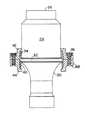
改良された、所謂堅い節装着手段の構造が図2及び図3に示されている。ブースターホーン24、即ち細長い丸い本体には、放射方向に置かれた入力表面26が設けられ、入力表面26は、電気音響変換器の出力表面へ機械的に接続され、そこから機械的高周波振動を受入れるようになっている。反対の放射方向に置かれた出力表面28は、振動をホーンの入力表面へ与え、次いで振動をワークピースへ伝える。上記の文献を参照。ここに示されているブースターホーンは、符号30にて概ね示された、入力表面26から出力表面28へ伝達される振動についての機械的増幅器として機能する利得部分を有する。
【0021】
所定の周波数の振動が伝達されると、ブースターホーンは、半波長共振体として共振され、かかる振動の節領域が入力表面及び出力表面に存在する腹領域の概ね中間に現れる。既に述べた如く、節領域の正確な位置は、ホーンの構造に依存している。図2に示されている如く、環状フランジ32は、ホーンの節領域から放射方向に突出する。フランジ32の各々の側には、同一の着座手段34及び36が設けられ、それらは、対応する可撓性チューブ38及び40の一方の端を受入れる。各々のチューブの他方の端は、把持手段42及び44の対応する半体に着座される。一組のねじ46は、把持手段の半体を互いに固定する。把持手段の外側表面48は、より大きなハウジングの円形溝内に装着されるよう構成され、これによりハウジングは振動部材、即ち共振体の積重体を支持する。
【0022】
チューブ38、40の外端は、図3に示す如く、把持手段の半体の対応する円筒状表面50及び52に対するプレスフィットを有する。着座部材34及び36は、L字形状となっている。着座手段の軸線方向に配置された円筒状の表面54及び56の寸法は、チューブ38及び40の内端に対するプレスフィットを構成するようになっている。プレスフィットを達成するために、各々の面取りされた表面58及び60が表面54及び56上にてチューブを案内するべくフランジ32の各々の側に配置されている。
【0023】
装着手段は、各々のチューブの一方の端を把持手段の半体42及び44の対応する一方の端へ押付けることによって組立てられる。表面50及び52が、チューブの外側直径よりも僅かに小さい内側直径を有するよう加工されていることにより、既に述べた如く、プレスフィットがなされる。把持手段の半体が、その中に強固に押付けられたチューブと共に、図3に示す如くブースターホーンの周りに配置され、ねじ46を締結することによって互いに閉じた状態となる。チューブ38及び40の内端は、対応する面取りされた表面58及び60上にて案内され、隣接する軸線方向表面54及び56上に押し付けられる。表面54及び56は、チューブ38及び40の内径よりも僅かに大きい直径を有する。把持手段の半体の各々の放射方向表面61及び62は、関連するチューブへ力を与え、ねじが閉められると、チューブは、面取りされた表面と、隣接した円筒状表面上を摺動し着座手段34及び36の放射方向表面上へ押付けられる。
【0024】
プレスフィットにより、チューブの内端が、フランジに対して相対的に運動することが抑えられ、外端が把持手段に対し相対的に移動することが抑えられる。典型的な場合、チューブは、アルミニウムから構成され、実質的に静止した把持手段から振動部材の節領域に於て現れる振動を分離するべく撓む若しくは放射方向に曲がるような寸法に構成された軸線方向の長さ及び壁厚となっている。ホーンが20kHz の超音波周波数にて共振されるような寸法に構成されている典型的な実施例に於ては、各々のチューブは、11.43mmの軸線方向長さを有し、55.4mmの外径及び1.29mmの壁厚を有する。図2及び図3から明らかな如く、チューブと把持手段との中間には、節領域に於けるホーンの放射方向運動により要求される如く、チューブが放射方向に撓み、静止した把持手段からブースターホーンの振動を分離することができるように充分なクリアランスが設けられる。
【0025】
本発明の構成に於ける利点は単純であるということである。しかしながら重要なことは、図2の改良された装着手段が図1の従来の技術に於ける構成と同一のハウジングへ機械的に適合するということである。この特徴は、既に備え付けられている装置から改良された性能を引出すことができるという点で重要である。
【0026】
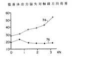
図4、図5及び図6は、ここに開示された新しい装着手段によって得られる改良された結果を示す。図4は、前記の積重体に於て測定された横方向の振れと側方荷重についての関係を示す。振れは、出力ホーンの中央部分若しくは節領域に於てmm単位で測定されている。荷重は、キロニュートンで測定されている。曲線70は、図1に示すOリングの組立体を示し、曲線72は、図2に示されている堅い装着構造を持って達成された大幅に低減された振れを示す。図5は、積重体に於ける出力損失と軸線方向荷重との関係を示す。曲線74は、エラストマ材からなるリングの構造上に於て得られた測定値を示し、曲線76は、図2に於ける構造についての大幅に低減された出力損失を示す。曲線74に於ける大きな出力損失は、基本的にはOリングの剛性の増大によるものである。図6は、振れと軸線方向荷重との関係を示す。再度、曲線78は、弾性的な装着構造に関したものであり、曲線80は、図2に於て示されている堅い装着構造に対応する。全ての例に於て達成されている改善点は重要である。
【0027】
本発明の好ましい実施例について説明され例示されているが、当業者にとって本発明の概念から逸脱することなく種々の変更及び改良は明らかであり、本発明は、実施例のみに限定されるべきものではない。
【図面の簡単な説明】
【図1】広く用いられている典型的な従来の技術に於ける装着手段の正面図。部分的に断面が示されている。
【図2】本発明の改良された装着手段の正面図。部分的に断面が示されている。
【図3】図2に示されている部分の拡大図。
【図4】図1の従来の技術に於ける構成及び図2に示されている改良された装着手段についての振れ対側方荷重の関係を示すグラフ図。
【図5】従来の技術に於ける装着手段と改良された本発明の装着手段についての積重体出力損失対軸線方向荷重との関係を示すグラフ図。
【図6】従来の技術に於ける装着手段と本発明による改良された節装着手段の構成についての振れ対軸線方向荷重との関係を示すグラフ図。
【符号の説明】
10…ブースターホーン(従来技術)
12…フランジ
14、16…Oリング
18、20…L型環状金属リング
22…放射方向ピン
24…ブースターホーン
26…入力表面
28…出力表面
32…フランジ
34、36…着座手段
38、40…可撓性チューブ
42、44…把持手段
46…ねじ
48…把持手段の外側表面
50、52…円筒状表面
54、56…軸線方向表面
58、60…面取りされた表面
61、62…放射方向表面[0001]
[Industrial application fields]
The present invention relatesto a vibration member mounting apparatus and a vibration member mounting method including ahigh-frequency vibration member and a mounting means for the vibration member , and more particularly, to a workpiece in a high-frequency range of sound waves or ultrasonic waves. It relates to a mountingdevice and method for a solid state resonator, also known as a mechanical impedance converter, sonotrode, horn, tool, concentrator, coupler etc. used to transmit vibrations.
[0002]
[Prior art]
High frequency vibration is used to bond abrasive slurries consisting of thermoplastic parts, welded metal parts, glass or ceramic workpieces. The construction and usage of these vibrating members are described in detail in “Ultrasonic Engineering” (book) by Julian R. Frederick, John Wiley & Sons, New York, NY (1965), pp. 89-103. Has been.
[0003]
The vibrating member resonates as a half-wave resonator so that a high-frequency vibration of a predetermined frequency is transmitted in the longitudinal direction during operation. The mounting means for the vibrating member must be configured so that its vibration is substantially separated from the mounting means without compromising the operation of the vibrating member. Without such separation, vibration energy is lost and vibrations are transmitted to the mounting means and other parts of the machine where vibration is very undesirable.
[0004]
The vibration member is usually attached to the fixed support portion by providing support means. The engagement between the support means and the vibrating member is such that high-frequency vibrations pass radially through the vibrating member along its longitudinal axis radially from the input surface at one end to the radial direction at the other end. This is done in the nodal or anti-node regions that occur in the vibrating member as it is transmitted to the placed output surface. Assuming a half-wave resonator under these conditions, there is a vibration antinode region on the input and output surfaces, and a vibration node region in the middle of these antinode regions. It becomes. The exact position of the nodal region depends on the mechanical configuration of the resonator. In the nodal region, the vibration appears as a vibration substantially in the radial direction.
[0005]
A mounting means using a flexible metal element that engages a vibrating member in the anti-vibration region of vibration is disclosed, for example, in US Pat. No. 3,752,380 “Vibratory Welding Apparatus”. It is disclosed. The disadvantage of that configuration is that the vibrating member must be at least one full wavelength long.
[0006]
Other mounting means coupled to the vibrating member are disclosed in U.S. Pat. Nos. 2,891,178, 2,891,179 and 2,891,180, “Supporting portion for vibrating device”. ("Support for Vibratory Devices"). These patents disclose various separating means that engage the vibrating member in the abdominal region. The separating means includes a tuned element with a length of 1/4 or 1/2 wavelength. These mounting means are not widely accepted because they are complex and require a lot of space, and are hardly seen as commercial devices.
[0007]
Due to the above drawbacks, several mounting means for supporting the vibration member in the node region have been developed. In the presently widely used configuration, the vibrating member is provided with a thin flange, and the thin flange protrudes radially from the vibration node region. An O-ring made of an elastomer material is arranged on either side of the flange, all of which are covered in a two piece metal annular ring. See U.S. Pat. No. 4,647,336. The elastomer material O-ring functions to reduce the vibration existing in the node region of the vibration member with respect to the annular ring fixed to the housing. However, although this configuration is widely used, it has some inherent problems. O-rings are easily worn, and elastic rings are used when the vibrating member is used for precision work, particularly when the vibrating member is moved in response to an axial or lateral direction. However, the desired rigidity cannot be obtained.
[0008]
In order to solve the above problem, a metal node region mounting means capable of obtaining greater rigidity has been developed. However, currently utilized configurations have significant drawbacks. In one configuration, the vibrating member and metal separation flange are made from a single piece, requiring complex and expensive processing operations. In another configuration, one L-shaped flange is used that is machined from rod stock and requires a relatively large space.
[0009]
SUMMARY OF THE INVENTION
The present invention discloses a compact and simple metal mounting member for a vibrating member. The vibrating member is provided with a cylindrical flange extending radially in the node region. The gripping means surrounds the vibration member. A pair of cylindrical flexible tubes is provided, and for each tube, one end is fixed to the corresponding side of the flange by press fit, and the other end of the tube is fixed to the gripping means by press fit. Is done. The gripping means includes two halves that are fixed together in the axial direction. Furthermore, both gripping means halves have radial surfaces for pressing each tube against a corresponding seating surface arranged on the flange. The cylindrical tube has a wall thickness and an axial length so that the tube can bend in the radial direction when the vibrating member vibrates in the radial direction in the node region. Thus, the tube isolates the vibration of the vibrating member from the gripping means supported in the stationary housing.
[0010]
One object of the present invention is to provide a new and improved mounting means for a vibrating member.
[0011]
Another object of the present invention is to provide a new and improved rigid mounting means for a vibrating member, particularly a resonant member adapted to resonate as a half-wave resonator.
[0012]
Another important object of the present invention is to provide a metal mounting means connected to the vibrating member in a region that becomes a node region when the vibrating member is resonated at a predetermined frequency. .
[0013]
A further object of the present invention is a mounting means for a vibrating member configured to resonate as a half-wave resonator, wherein the vibration appearing in a nodal region of the vibrating member is substantially fixed surrounding the vibrating member. It is an object of the present invention to provide a mounting means including a pair of cylindrical tubes for separation from the gripping means.
[0014]
Another further object of the present invention is a metal rigid mounting means for a vibrating member, which engages the vibrating member in its nodal region, is simple in construction and low in cost. It is to provide a mounting means that is characterized.
[0015]
Still another object of the present invention is a node mounting portion for a vibration member, which exhibits greater rigidity than conventional means using an elastic ring for isolating vibration and has low output loss. It is to provide mounting means.
[0016]
Other objects of the present invention will become more apparent from the following description in conjunction with the accompanying drawings.
[0017]
【Example】
The mounting means described below is an elongated resonator, and is a resonator sized so as to resonate as a half-wave resonator when high-frequency vibration of a predetermined frequency is transmitted in the longitudinal direction. It is suitable for mounting in a node region of longitudinal vibration. In a typical industrial device, the predetermined frequency is in the ultrasonic range, for example 20 kHz, and the device uses a stack of three vibrating members, ie an applied electrical high frequency energy. It includes an electroacoustic transducer for converting to mechanical vibration, an intermediate coupler, also known as a “booster horn”, and a stack of output horns, tools, sonotrode and the like. The vibration from the transducer is received by the intermediate coupler and transmitted to the output horn or the like with the same or increased intensity and then to the workpiece. In order to operate, all members of the stack are dimensioned to resonate at the predetermined frequency. In addition to functioning as a mechanical impedance converter, the booster horn functions in most cases as a means for supporting the stack in a stationary housing. The following description describes the mounting means associated with the booster horn, but the present invention is applicable to other vibrating members having similar properties.
[0018]
With particular reference to FIG. 1, there is shown mounting means in the widely used prior art.
[0019]
The fact that the mounting means in the prior art has inherent disadvantages in the stiffness of the stack due to the elasticity of the O-ring, and that the O-ring is subject to aging and wear due to the dissipation of vibration energy. Will be understood.
[0020]
An improved construction of the so-called rigid node attachment means is shown in FIGS. The
[0021]
When vibration of a predetermined frequency is transmitted, the booster horn is resonated as a half-wave resonator, and a node region of such vibration appears approximately in the middle of the antinode region existing on the input surface and the output surface. As already mentioned, the exact position of the nodal region depends on the structure of the horn. As shown in FIG. 2, the
[0022]
The outer ends of the
[0023]
The mounting means is assembled by pressing one end of each tube against the corresponding one end of the gripping means
[0024]
By a press fit, the inner end of the tube, it is suppressed to move relative with respect toflange, it is suppressed that the outer end is relatively moved with respect to the gripping means. Typically, the tube is made of aluminum and is sized to flex or bend in a radial direction to isolate vibrations appearing in the nodal region of the vibrating member from the substantially stationary gripping means. The direction length and wall thickness. In an exemplary embodiment in which the horn is sized to resonate at an ultrasonic frequency of 20 kHz, each tube has an axial length of 11.43 mm and 55.4 mm. And an outer wall thickness of 1.29 mm. As apparent from FIGS. 2 and 3, between the tube and the gripping means, the tube is deflected radially as required by the radial movement of the horn in the nodal region, and the booster horn is moved from the stationary gripping means. Sufficient clearance is provided so that the vibrations can be isolated.
[0025]
The advantage in the configuration of the present invention is that it is simple. Importantly, however, the improved mounting means of FIG. 2 is mechanically compatible with the same housing as the prior art configuration of FIG. This feature is important in that improved performance can be derived from already installed equipment.
[0026]
4, 5 and 6 show the improved results obtained with the new mounting means disclosed herein. FIG. 4 shows the relationship between lateral runout and lateral load measured in the stack. The runout is measured in mm at the center or nodal region of the output horn. The load is measured in kilonewtons.
[0027]
While the preferred embodiment of the invention has been illustrated and illustrated, various changes and modifications will be apparent to those skilled in the art without departing from the inventive concept, the invention should be limited only to the embodiment. is not.
[Brief description of the drawings]
FIG. 1 is a front view of mounting means in typical prior art that is widely used. A cross section is partially shown.
FIG. 2 is a front view of the improved mounting means of the present invention. A cross section is partially shown.
FIG. 3 is an enlarged view of the portion shown in FIG.
4 is a graph showing the relationship between run-out and side load for the prior art configuration of FIG. 1 and the improved mounting means shown in FIG. 2;
FIG. 5 is a graph showing the relationship between the stack output loss and the axial load for the mounting means in the prior art and the improved mounting means of the present invention.
FIG. 6 is a graph showing the relationship between run-out and axial load for the configuration of the mounting means in the prior art and the improved node mounting means according to the present invention.
[Explanation of symbols]
10 ... Booster horn (prior art)
12 ...
Claims (6)
Translated fromJapanese前記振動部材が、実質的に前記節領域にて前記振動部材から放射方向に延在し支持表面(34、36)を含むフランジ(32)を有し、
前記装着手段が、実質的に前記フランジの在る位置にて前記振動部材を囲繞する一対の装着環状体(42、44)を含み、
該装着環状体の各々が、該装着環状体の各々に結びつけられてそれら各々から軸線方向に延在する筒状の可撓性チューブ(38、40)を有し、該可撓性チューブ(38、40)の各々が前記フランジの前記支持表面のうちの対応する一方に押圧する端部を有し、前記フランジに対して前記可撓性チューブを軸線方向に把持する把持手段(42、44、46)が設けられ、該把持手段が、前記可撓性チューブの前記端部が前記支持表面を押圧するよう前記可撓性チューブを把持し、これにより、前記チューブの端部とそれに対応する前記支持表面との間の相対的な運動が抑えられ、
前記可撓性チューブの各々が、前記振動部材が共振してその前記節領域にて実質的に放射方向に運動することに応答して放射方向に撓めるような軸線方向長さと壁厚を有し、これにより、前記可撓性チューブが前記振動部材の振動を該把持手段から分離することを特徴とする振動部材装着装置。The vibration member (24) is configured to resonate as a resonator with vibrations of a predetermined frequency transmitted in the longitudinal direction thereof,and the vibration member generates two antinode regions and one node region when resonating.A vibration member mounting device comprising mounting means for the vibration member ,
The vibrating member has a flange (32)that extends radially from the vibrating member substantially in the nodal region and includes support surfaces (34, 36);
The mounting meansincludes a pair of mounting annular bodies (42, 44)that surround the vibration member substantially at a position where the flange exists.
Each of the mounting annulus has atubular flexible tube (38, 40) associated with each of the mounting annulus and extending axially therefrom, the flexible tube (38 ,gripping means (42, 44, each of the 40)have a end forpressing the corresponding one of said support surface of saidflange, gripping the flexible tube in the axial direction with respect to the flange, 46), and the gripping means grips the flexible tube such that the end of the flexible tube presses against the support surface, whereby the end of the tube and the corresponding end of the tube The relative movement between the support surface is suppressed,
Each of the flexible tubes has an axial length and wall thickness such that the vibrating member bends radially in response to resonating and substantially radially moving in the nodal region. Accordingly, the flexible tube separates the vibration of the vibration member from the gripping means.
前記フランジが実質的に前記節領域にて前記振動部材から放射方向に延在する実質的に円筒の断面を有し、前記フランジの前記支持表面(34、36)が各々の側に下記の対応する可撓性チューブ(38、40)の一方の端を受入れ且前記対応するチューブの一方の端と前記振動部材との間の相対的な運動を抑えるべく前記対応するチューブの前記一方の端と強固に係合し、
前記可撓性チューブが、前記振動部材の実質的に軸線方向に同芯状に延在する金属チューブ(38、40)であり、それらの一方が前記フランジの一方の側上にある前記支持表面上に配置されており、他方が前記フランジの他方の側上にある前記支持表面上に配置され、
前記装着環状体(42、44)が、環状に形成され、前記チューブの各々の他方の端に係合するよう配置され、前記チューブの前記他方の端が前記装着環状体に対して放射方向に運動することを抑えるべく前記チューブの各々の前記他方の端に強固に係合するための第一の表面手段(50、52)を含み、前記チューブと前記支持表面との間にて軸線方向の係合力を与えるための第二の表面手段(61、62)を有していることを特徴とする振動部材装着装置The vibrating member mounting device according to claim 1,an elongated substantially cylindrical vibrationmemberthe vibration member is configured dimensioned to resonate as a half wavelength resonator with the vibration of a predetermined frequency transmitted in the longitudinal direction(24)
It said flange is substantially thehave a substantially cylindrical cross-section extending radially from the vibration member in the noderegion, corresponding below on the side ofsaid support surface of said flange (34, 36) are each Receiving one end of the flexible tube (38, 40) and the one end of the corresponding tube to suppress relative movement between the one end of the corresponding tube and the vibrating member; firmlyengaged,
Thesupport surfacewherein the flexible tube is a metal tube (38, 40) extending concentrically in a substantially axial direction of the vibrating member, one of which is on one side of the flange Arranged on thesupport surface , the other being on the other side of the flange,
The mounting ring (42, 44) is formed in an annular shape and is arranged to engage the other end of each of the tubes, the other end of the tube being in a radial direction with respect to themounting ring First surface means (50, 52) for tightly engaging the other end of each of the tubes to prevent movement, axially between the tube and thesupport surface .A vibration member mounting device having second surface means (61, 62) for applying an engaging force
前記可撓性チューブが互いに反対方向へ軸線方向に延在し、前記可撓性チューブの各々の端部が前記フランジの前記支持表面のうちの対応する一方に係合し、共振している前記振動部材に応答して前記可撓性チューブが放射方向に撓めるよう前記フランジの前記支持表面に前記一対の可撓性チューブを配置する過程と、
前記フランジに対して前記可撓性チューブを軸線方向に把持する把持手段(42、44、46)によって、前記可撓性チューブの前記端部が前記支持表面を押圧し、これにより、前記可撓性チューブの前記端部と前記フランジとの間の相対的な運動を実質的に禁止し前記支持部材から前記フランジに現れる振動を分離するよう前記フランジの前記支持表面に対して前記可撓性チューブを把持する過程とを含む方法。And the vibration member (24) has one nodal region upon configured resonant dimensioned to resonate as a resonator to vibrate at a predetermined frequency transmitted in the longitudinal direction,the vibration member in substantially the node region A surface (34) for receiving acylindrical flexible tube (38, 40) havinga flange (32)extending radially from the flange, the flangesextending in opposite directions in a pair of axial directions. , 36) in order to separate the vibration of the vibration member from the support member, the vibration member is attached to the support member,
The flexible tubes extend axially in opposite directions and each end of the flexible tube engages a corresponding one of the support surfaces of the flange and is in resonance Arranging the pair of flexible tubes on the support surface of the flange such that the flexible tubes are deflected radially in response to a vibrating member;
By means of gripping means (42, 44, 46) for gripping the flexible tube against the flange in the axial direction, the end of the flexible tube presses the support surface, thereby causing the flexibility of the flexible tube. The flexible tube relative to the support surface of the flange to substantially inhibit relative movement between the end of the flexible tube and the flange and to isolate vibrations appearing on the flange from the support member. Gripping the method.
前記支持表面に対して前記可撓性チューブを把持する前記過程が、前記チューブの各々の端部をそれに対応する前記フランジの前記支持表面に係合し、前記チューブの各々の前記内壁をその対応する前記円筒状位置決め表面にプレスフィットするよう前記可撓性チューブの各々を前記フランジに対し軸線方向に把持することを含む方法。A method according to claim 5, wherein each of said flexible tube has an inner wall,the flange, a support surface facing the axial direction of both of the vibration member, radially inward from the support surface Spaced cylindrical positioning surfaces (54, 56) are provided;
The process of gripping the flexible tube against thesupport surface engages each end of the tube with the corresponding support surface of the flange and the inner wall of each of the tubes correspondingly. Gripping each of the flexible tubes axially with respect to the flange to press fit the cylindrical positioning surface.
Applications Claiming Priority (2)
| Application Number | Priority Date | Filing Date | Title |
|---|---|---|---|
| US08/194,108US5443240A (en) | 1994-02-09 | 1994-02-09 | Mounting means for vibration member |
| US194108 | 1994-02-09 |
Publications (2)
| Publication Number | Publication Date |
|---|---|
| JPH07213998A JPH07213998A (en) | 1995-08-15 |
| JP3650158B2true JP3650158B2 (en) | 2005-05-18 |
Family
ID=22716334
Family Applications (1)
| Application Number | Title | Priority Date | Filing Date |
|---|---|---|---|
| JP03603695AExpired - LifetimeJP3650158B2 (en) | 1994-02-09 | 1995-02-01 | Vibration member mounting apparatus and method for mounting vibration member |
Country Status (7)
| Country | Link |
|---|---|
| US (2) | US5443240A (en) |
| EP (1) | EP0667189B1 (en) |
| JP (1) | JP3650158B2 (en) |
| KR (1) | KR950033226A (en) |
| CA (1) | CA2130209C (en) |
| DE (1) | DE69515921T2 (en) |
| TW (1) | TW290486B (en) |
Families Citing this family (33)
| Publication number | Priority date | Publication date | Assignee | Title |
|---|---|---|---|---|
| US5443240A (en)* | 1994-02-09 | 1995-08-22 | Branson Ultrasonics Corporation | Mounting means for vibration member |
| SE9502226L (en)* | 1995-06-19 | 1996-12-20 | Tetra Laval Holdings & Finance | Device at a drive for an ultrasonic sealing device |
| US5788791A (en)* | 1996-07-03 | 1998-08-04 | Branson Ultrasonics Corporation | Method of determining the collapse of plastic parts |
| RU2141386C1 (en)* | 1997-12-15 | 1999-11-20 | Бийский технологический институт Алтайского государственного технического университета им.И.И.Ползунова | Ultrasonic oscillation system |
| US6434244B1 (en)* | 2000-04-26 | 2002-08-13 | Branson Ultrasonics Corporation | Electroacoustic converter |
| US6561983B2 (en) | 2001-01-31 | 2003-05-13 | Ethicon Endo-Surgery, Inc. | Attachments of components of ultrasonic blades or waveguides |
| JP3568496B2 (en)* | 2001-07-06 | 2004-09-22 | 株式会社アルテクス | Ultrasonic wire bonding resonator |
| US6634539B2 (en) | 2001-09-21 | 2003-10-21 | 3M Innovative Properties Company | Adjustable-gap rotary ultrasonic horn mounting apparatus and method for mounting |
| JP3466175B2 (en)* | 2001-12-03 | 2003-11-10 | 三島 大二 | Ultrasonic vibration horn |
| GB0130129D0 (en)* | 2001-12-17 | 2002-02-06 | Purac Ltd | Apparatus for generating ultrasound |
| US6547903B1 (en)* | 2001-12-18 | 2003-04-15 | Kimberly-Clark Worldwide, Inc. | Rotary ultrasonic bonder or processor capable of high speed intermittent processing |
| US6620270B2 (en) | 2001-12-18 | 2003-09-16 | Kimberly-Clark Worldwide, Inc. | Control of processing force and process gap in rigid rotary ultrasonic systems |
| US6613171B2 (en) | 2001-12-18 | 2003-09-02 | Kimberly-Clark Worldwide, Inc. | Rotary ultrasonic bonder or processor capable of fixed gap operation |
| US6537403B1 (en) | 2001-12-18 | 2003-03-25 | Kimberly-Clark Worldwide, Inc. | Nip adjustment for a rigid ultrasonic bonder or processor |
| US6676003B2 (en)* | 2001-12-18 | 2004-01-13 | Kimberly-Clark Worldwide, Inc. | Rigid isolation of rotary ultrasonic horn |
| US7243894B2 (en) | 2002-02-15 | 2007-07-17 | 3M Innovative Properties Company | Mount for vibratory elements |
| US6984921B1 (en)* | 2003-02-21 | 2006-01-10 | Dukane Corporation | Apparatus and method for resonant mounting of vibration structure |
| US7297238B2 (en)* | 2003-03-31 | 2007-11-20 | 3M Innovative Properties Company | Ultrasonic energy system and method including a ceramic horn |
| US6786384B1 (en)* | 2003-06-13 | 2004-09-07 | 3M Innovative Properties Company | Ultrasonic horn mount |
| US7137543B2 (en)* | 2004-07-28 | 2006-11-21 | Kulicke And Soffa Industries, Inc. | Integrated flexure mount scheme for dynamic isolation of ultrasonic transducers |
| FR2893094B1 (en)* | 2005-11-10 | 2011-11-11 | Cit Alcatel | FIXING DEVICE FOR A VACUUM PUMP |
| US20070246237A1 (en)* | 2006-04-24 | 2007-10-25 | Emile Homsi | Vibration dampening of a power tool |
| US8212171B2 (en)* | 2006-12-22 | 2012-07-03 | Sonics & Materials Inc. | System and method for ultrasonic assisted EDM machining |
| DE102008002744A1 (en)* | 2008-06-27 | 2009-12-31 | Herrmann Ultraschalltechnik Gmbh & Co. Kg | Ultrasonic vibration unit with bracket |
| US8113258B2 (en)* | 2008-07-08 | 2012-02-14 | Sonics & Materials Inc. | Ultrasonic welding device |
| DE102009048696B3 (en)* | 2009-10-08 | 2011-06-09 | Kunststoff-Zentrum in Leipzig gemeinnützige Gesellschaft mbH | Sonotrode arrangement for e.g. plastic machining and processing tools used in ultrasonic welding of workpiece, has fitting groove arranged in end region that lies opposite to clamping position of slot |
| JP5878299B2 (en)* | 2010-04-27 | 2016-03-08 | 株式会社アドウェルズ | Ultrasonic vibration cutting device |
| KR101521075B1 (en) | 2010-04-29 | 2015-05-18 | 에디슨 웰딩 인스티튜트, 인코포레이티드 | Ultrasonic machining assembly for use with portable devices |
| US10381321B2 (en) | 2017-02-18 | 2019-08-13 | Kulicke And Soffa Industries, Inc | Ultrasonic transducer systems including tuned resonators, equipment including such systems, and methods of providing the same |
| DE102018132838A1 (en)* | 2018-12-19 | 2020-06-25 | Herrmann Ultraschalltechnik Gmbh & Co. Kg | Ultrasonic welding system with bracket |
| DE102018132837A1 (en) | 2018-12-19 | 2020-06-25 | Herrmann Ultraschalltechnik Gmbh & Co. Kg | Ultrasonic welding system |
| US11976951B2 (en)* | 2020-09-25 | 2024-05-07 | Krohne Messtechnik Gmbh | Ultrasonic transducer including separately-excitable electro-acoustic discs, ultrasonic flowmeter including the ultrasonic transducer, and related methods for operating the ultrasonic transducer and ultrasonic flowmeter |
| DE102021118168A1 (en) | 2021-07-14 | 2023-01-19 | Herrmann Ultraschalltechnik Gmbh & Co. Kg | Ultrasonic oscillating element with compensation element |
Family Cites Families (9)
| Publication number | Priority date | Publication date | Assignee | Title |
|---|---|---|---|---|
| US2891179A (en)* | 1957-08-19 | 1959-06-16 | Aeroprojects Inc | Support for vibratory devices |
| US2891178A (en)* | 1957-08-19 | 1959-06-16 | Aeroprojects Inc | Support for vibratory devices |
| US2891180A (en)* | 1957-08-19 | 1959-06-16 | Aeroprojects Inc | Support for vibratory devices |
| US3429028A (en)* | 1965-06-28 | 1969-02-25 | Sonobond Corp | Vibratory welding apparatus and method |
| US3679526A (en)* | 1970-04-08 | 1972-07-25 | Branson Instr | Sonic or ultrasonic cutting apparatus |
| US3752380A (en)* | 1972-03-13 | 1973-08-14 | Branson Instr | Vibratory welding apparatus |
| AU8012482A (en)* | 1981-02-04 | 1982-08-12 | Eaton Corporation | Ultrasonic atomizer |
| US4647336A (en)* | 1985-03-08 | 1987-03-03 | Kimberly-Clark Corporation | Rebuildable support assembly |
| US5443240A (en)* | 1994-02-09 | 1995-08-22 | Branson Ultrasonics Corporation | Mounting means for vibration member |
- 1994
- 1994-02-09USUS08/194,108patent/US5443240A/ennot_activeExpired - Lifetime
- 1994-08-08CACA002130209Apatent/CA2130209C/ennot_activeExpired - Fee Related
- 1995
- 1995-02-01JPJP03603695Apatent/JP3650158B2/ennot_activeExpired - Lifetime
- 1995-02-06KRKR1019950002049Apatent/KR950033226A/ennot_activeAbandoned
- 1995-02-08TWTW084101024Apatent/TW290486B/zhactive
- 1995-02-09EPEP95630011Apatent/EP0667189B1/ennot_activeExpired - Lifetime
- 1995-02-09DEDE69515921Tpatent/DE69515921T2/ennot_activeExpired - Lifetime
- 1995-07-25USUS08/507,053patent/US5590866A/ennot_activeExpired - Lifetime
Also Published As
| Publication number | Publication date |
|---|---|
| US5443240A (en) | 1995-08-22 |
| TW290486B (en) | 1996-11-11 |
| DE69515921D1 (en) | 2000-05-04 |
| US5590866A (en) | 1997-01-07 |
| EP0667189B1 (en) | 2000-03-29 |
| DE69515921T2 (en) | 2000-10-26 |
| EP0667189A2 (en) | 1995-08-16 |
| JPH07213998A (en) | 1995-08-15 |
| CA2130209A1 (en) | 1995-08-10 |
| EP0667189A3 (en) | 1997-07-09 |
| CA2130209C (en) | 1997-04-29 |
| KR950033226A (en) | 1995-12-22 |
Similar Documents
| Publication | Publication Date | Title |
|---|---|---|
| JP3650158B2 (en) | Vibration member mounting apparatus and method for mounting vibration member | |
| GB1599461A (en) | Ultrasonic transducer | |
| US3955740A (en) | Vibratory seam welding apparatus | |
| JP4116570B2 (en) | Mounting system for a vibrating element and method for forming a mounting system | |
| TW422771B (en) | Non-nodal mounting system for acoustic horn | |
| US8113258B2 (en) | Ultrasonic welding device | |
| KR101577088B1 (en) | Resonant nodal mount for linear ultrasonic horns | |
| JP2583398B2 (en) | Ultrasonic welding equipment | |
| EP1633497B1 (en) | Ultrasonic horn mount | |
| CN113226619A (en) | Ultrasonic welding system with support element | |
| EP3898012A1 (en) | Vibration conversion apparatus | |
| JPH0957466A (en) | Ultrasonic bonding device and resonator | |
| CN113165019B (en) | Ultrasonic welding system with retainer | |
| US6984921B1 (en) | Apparatus and method for resonant mounting of vibration structure | |
| CN111356538A (en) | Ultrasonic vibration unit with damping | |
| JPH09253869A (en) | Ultrasonic welding equipment | |
| JP2018507780A (en) | Screening system, eddy current screening machine, and use of screening system or eddy current screening machine | |
| JP2005094448A (en) | Electromagnetic conversion device for acoustic radiation device, and acoustic radiation device | |
| JPS6097076A (en) | Improvement in joint assembly | |
| RU1813231C (en) | Electromechanical transducer | |
| MXPA00011175A (en) | Non-nodal mounting system for acoustic horn | |
| JPH05116060A (en) | Ultrasonic processing machine | |
| WO2017032958A1 (en) | Ultrasonically vibrated die rings |
Legal Events
| Date | Code | Title | Description |
|---|---|---|---|
| A131 | Notification of reasons for refusal | Free format text:JAPANESE INTERMEDIATE CODE: A131 Effective date:20040622 | |
| A601 | Written request for extension of time | Free format text:JAPANESE INTERMEDIATE CODE: A601 Effective date:20040922 | |
| A602 | Written permission of extension of time | Free format text:JAPANESE INTERMEDIATE CODE: A602 Effective date:20040928 | |
| A521 | Request for written amendment filed | Free format text:JAPANESE INTERMEDIATE CODE: A523 Effective date:20041112 | |
| TRDD | Decision of grant or rejection written | ||
| A01 | Written decision to grant a patent or to grant a registration (utility model) | Free format text:JAPANESE INTERMEDIATE CODE: A01 Effective date:20050118 | |
| A61 | First payment of annual fees (during grant procedure) | Free format text:JAPANESE INTERMEDIATE CODE: A61 Effective date:20050217 | |
| R150 | Certificate of patent or registration of utility model | Free format text:JAPANESE INTERMEDIATE CODE: R150 | |
| FPAY | Renewal fee payment (event date is renewal date of database) | Free format text:PAYMENT UNTIL: 20090225 Year of fee payment:4 | |
| FPAY | Renewal fee payment (event date is renewal date of database) | Free format text:PAYMENT UNTIL: 20090225 Year of fee payment:4 | |
| FPAY | Renewal fee payment (event date is renewal date of database) | Free format text:PAYMENT UNTIL: 20100225 Year of fee payment:5 | |
| FPAY | Renewal fee payment (event date is renewal date of database) | Free format text:PAYMENT UNTIL: 20100225 Year of fee payment:5 | |
| FPAY | Renewal fee payment (event date is renewal date of database) | Free format text:PAYMENT UNTIL: 20110225 Year of fee payment:6 | |
| FPAY | Renewal fee payment (event date is renewal date of database) | Free format text:PAYMENT UNTIL: 20120225 Year of fee payment:7 | |
| FPAY | Renewal fee payment (event date is renewal date of database) | Free format text:PAYMENT UNTIL: 20130225 Year of fee payment:8 | |
| FPAY | Renewal fee payment (event date is renewal date of database) | Free format text:PAYMENT UNTIL: 20130225 Year of fee payment:8 | |
| FPAY | Renewal fee payment (event date is renewal date of database) | Free format text:PAYMENT UNTIL: 20140225 Year of fee payment:9 | |
| R250 | Receipt of annual fees | Free format text:JAPANESE INTERMEDIATE CODE: R250 | |
| EXPY | Cancellation because of completion of term |