JP3647592B2 - Plasma source, ion source using the same, and plasma processing apparatus - Google Patents
Plasma source, ion source using the same, and plasma processing apparatusDownload PDFInfo
- Publication number
- JP3647592B2 JP3647592B2JP04942097AJP4942097AJP3647592B2JP 3647592 B2JP3647592 B2JP 3647592B2JP 04942097 AJP04942097 AJP 04942097AJP 4942097 AJP4942097 AJP 4942097AJP 3647592 B2JP3647592 B2JP 3647592B2
- Authority
- JP
- Japan
- Prior art keywords
- plasma
- conductor
- generation chamber
- plasma generation
- dielectric
- Prior art date
- Legal status (The legal status is an assumption and is not a legal conclusion. Google has not performed a legal analysis and makes no representation as to the accuracy of the status listed.)
- Expired - Fee Related
Links
Images


Landscapes
- Electron Sources, Ion Sources (AREA)
- Drying Of Semiconductors (AREA)
- Cleaning Or Drying Semiconductors (AREA)
- Plasma Technology (AREA)
- Chemical Vapour Deposition (AREA)
- ing And Chemical Polishing (AREA)
Description
Translated fromJapanese【0001】
【産業上の利用分野】
本発明は半導体や液晶パネル、太陽電池等の薄膜形成工程、および微細なパターンを形成するためのエッチング工程、および表面洗浄工程に用いられるプラズマ源及びそれを用いたイオン源並びにプラズマ処理装置に関するものである。
【0002】
【従来の技術】
近年、プラズマ処理装置は高機能化とその処理コストの低減のために、高速化、高品質化、大面積化処理を実現する取り組みが盛んに行われている。その中の1つに表面波を利用したプラズマ処理装置がある。たとえばK.コマチ、ジャーナルオブバキュームサイエンスアンドテクノロジーA,第12巻,p.769,1994年(K.Komachi, Journal of Vacuum Science & Technology A,Vol.12, p.769(1994))等には以下に述べるようにマイクロ波を導体上の誘電体板に導入する方式の表面波励起型プラズマ処理装置が提案されている。
【0003】
このような従来のプラズマ処理装置の一例としては図11に示すものがある。図11は従来のプラズマ処理装置の反応室の断面図を示すものである。図11において,1は真空排気手段を備えた真空保持可能な真空容器で放電空間を形成する。2は被処理基板、3は排気口、4はガス導入口、5はマイクロ波を伝搬する矩形導波管、6は矩形導波管と連続した導体板、7は一部導波管内部挿入され導体板に張り付けられた誘電体板、8は真空機密を保つためのガラス板であり、誘電体板とガラス板の間にはギャップ9が設けられている。
【0004】
以上のように構成された従来のプラズマ処理装置について、以下その動作について説明する。まず、ガス導入口4を通してアルゴンや酸素のようなガスを30Pa(パスカル)程度真空容器1に導入する。次に矩形導波管5を通して2.45GHz・のマイクロ波10を誘電体板7の側面から内部に供給する。そして、マイクロ波は導体板6と誘電体板7の界面および誘電体板7とギャップ9の界面で反射しながら誘電体板7の内部を平面波として伝搬する。ここで、誘電体板7とギャップ9との界面でマイクロ波が全反射をしたとき、ギャップ9側に電磁界が指数関数的に減衰し減衰方向には波の形をとらないエバネセント波を発生させる。誘電体板7の表面から離れるに従って弱くなるエバネセント波は、誘電体板7表面に沿って伝わる波となることができ、これを一般に表面波と呼んでいる。この場合、エバネセント波のギャップ9側への侵入深さは波長程度(2.45GHz・のマイクロ波では約12.4cm)となるので、ガラス板を透過して真空容器1内にも漏れ出す。このエバネセント波により真空容器1内で導入ガスの放電が起こり、プラズマが生成する。このプラズマ中に発生したイオンや活性子に被処理基板2をさらすことにより洗浄などのプラズマ処理を行うことができる。
【0005】
【発明が解決しようとする課題】
しかしながら上記従来の構成では、エバネセント波の強度が弱く低ガス圧でプラズマを維持することが困難であり、また、平面波の強度分布が直接プラズマ密度分布に反映するので均一性が悪く大面積の基板に対しては適用でき難いという問題点を有していた。
【0006】
本発明は上記従来の問題点を解決するもので、低ガス圧力領域で高密度のプラズマが生成でき大面積の基板でも均一に処理することができるプラズマ処理装置を提供することを目的とする。
【0007】
【問題を解決するための手段】
この目的を達成するために本発明は、プラズマを発生させるプラズマ生成室と、前記プラズマ生成室に隣接し且つ第1の導体と第2の導体とを用いて形成した導波管と、前記第1の導体の少なくとも一部分とそれに対向する前記第2の導体の部分との両方に接するように前記第1の導体と前記第2の導体との間に挿入されて電磁波を伝搬させる誘電体と、を有するプラズマ源であって、前記第1の導体と前記第2の導体とのいずれか一方の導体が前記プラズマ生成室との接続部を有するとともに、前記接続部は前記電磁波の波長より短い径の開口を有し、前記電磁波が前記誘電体を伝搬することで前記開口を通して前記プラズマ生成室側に発生するエバネッセント波により前記プラズマ生成室にプラズマを発生させるように構成したものである。
また、本発明は、プラズマを発生させるプラズマ生成室と、前記プラズマ生成室内に少なくとも一部が配置され且つ第1の導体と第2の導体とを用いて形成した導波管と、前記第1の導体の少なくとも一部とそれに対向する前記第2の導体の部分との両方に接するように前記第1の導体と前記第2の導体との間に挿入されて電磁波を伝搬させる誘電体と、を有するプラズマ源であって、前記第1の導体と前記第2の導体とのいずれか一方または両方の導体が前記プラズマ生成室との接続部を有するとともに、前記接続部は前記電磁波の波長より短い径の開口を有し、前記電磁波が前記誘電体を伝搬することで前記開口を通して前記プラズマ生成室側に発生するエバネッセント波により前記プラズマ生成室にプラズマを発生させるように構成したものである。
【0008】
この構成によって、開口から発生したエバネセント波は開口径に応じて電界強度分布と侵入深さを変えることができ、また、開口の配置を最適化することにより電磁界分布の大面積均一性をよくし、低ガス圧でも強電界により高密度で均一なプラズマを発生させることができ、大面積の基板でも高速に均一に処理することができる。
【0009】
また、本発明の別の態様では、プラズマ生成室で発生したプラズマに電圧を印加してイオンビームを生成する手段を設けたことを要旨とする。
【0010】
【発明の実施の形態】
本発明の請求項1に記載の発明は、プラズマを発生させるプラズマ生成室と、前記プラズマ生成室に隣接し且つ第1の導体と第2の導体とを用いて形成した導波管と、前記第1の導体の少なくとも一部分とそれに対向する前記第2の導体の部分との両方に接するように前記第1の導体と前記第2の導体との間に挿入されて電磁波を伝搬させる誘電体と、を有するプラズマ源であって、前記第1の導体と前記第2の導体とのいずれか一方の導体が前記プラズマ生成室との接続部を有するとともに、前記接続部は前記電磁波の波長より短い径の開口を有し、前記電磁波が前記誘電体を伝搬することで前記開口を通して前記プラズマ生成室側に発生するエバネッセント波により前記プラズマ生成室にプラズマを発生させるプラズマ源であり、前記開口を透過した電磁波が前記プラズマ生成室内のガスに印加されることにより前記プラズマ生成室にプラズマを発生させるという作用を有する。
【0011】
本発明の請求項2に記載の発明は、プラズマを発生させるプラズマ生成室と、前記プラズマ生成室内に少なくとも一部が配置され且つ第1の導体と第2の導体とを用いて形成した導波管と、前記第1の導体の少なくとも一部とそれに対向する前記第2の導体の部分との両方に接するように前記第1の導体と前記第2の導体との間に挿入されて電磁波を伝搬させる誘電体と、を有するプラズマ源であって、前記第1の導体と前記第2の導体とのいずれか一方または両方の導体が前記プラズマ生成室との接続部を有するとともに、前記接続部は前記電磁波の波長より短い径の開口を有し、前記電磁波が前記誘電体を伝搬することで前記開口を通して前記プラズマ生成室側に発生するエバネッセント波により前記プラズマ生成室にプラズマを発生させるプラズマ源であり、前記開口を透過した電磁波が前記プラズマ生成室内のガスに印加されることにより前記プラズマ生成室にプラズマを発生させるという作用を有する。
【0012】
本発明の請求項3に記載の発明は、請求項1または2記載のプラズマ源において、第1の導体及び第2の導体は、同軸上に配置された円筒部材により構成したものである。
【0013】
本発明の請求項4に記載の発明は、請求項1から3のいずれかに記載のプラズマ源において、第1の導体及び/または第2の導体に複数の開口を有するようにしたものである。
【0016】
本発明の請求項5に記載の発明は、請求項1から4のいずれかに記載のプラズマ源において、電磁波はマイクロ波としたものである。
【0018】
本発明の請求項6に記載の発明は、請求項1から5のいずれかに記載のプラズマ源に対して、更にプラズマ生成室内に発生したプラズマに電圧を印加してイオンビームを生成する電極を、プラズマ生成室に隣接して設けたものである。
【0019】
本発明の請求項7に記載の発明は、請求項1から5のいずれかに記載のプラズマ源に対して、プラズマ生成室は、真空排気手段を備えた真空容器であり、前記真空容器内は、被処理基板を設置してプラズマ処理可能とするようにしたものであり、開口から漏れ出てくる電磁波で、均一高密度にプラズマを発生させることができ、大面積の基板でも均一に処理できるという作用を有する。
【0020】
(実施の形態1)
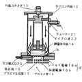
以下本発明の第1の実施の形態について、図面を参照しながら説明する。図1、図2は、それぞれ、本発明の第1の実施の形態のプラズマ源を用いたイオンビーム源(以下「イオン源」という)の断面鳥瞰図と断面図を示す。図1及び図2において、11は半同軸キャビティで、第1の導体に相当する外部導体(たとえば、内径76.9mm、長さ152.3mm・)11aと、第2の導体に相当する中心導体(たとえば、外径33.4mm、長さ132.3mm・)11bとから成っており、テフロン円板12で支持されている。半同軸キャビティ11の一方にはN型コネクタ13が付けてあり、他の一方の中心導体11bの端末には誘電体円板14が設置されている。誘電体円板14は、たとえば、径52mm、厚さ10mmのパイレックスガラスでできている。誘電体円板14の一方の平面は第2の導体である中心導体11bの端面と接しており、他の一方は第1の導体である外部導体11aと接しており、誘電体円板14と接している外部導体11aは、多孔板15(開口部)となっている。多孔板15は、例えば、径40mm、厚さ0.5mm・のステンレス板でできており、φ1.7mm・の開口16が等間隔で169・個開けてある。多孔板15の先には、たとえば、内径40mm、長さ11mmの円盤状の空間であるプラズマ生成室17が設けられている。以上の構成がプラズマ源に相当する。
【0021】
また、プラズマ生成室17で発生したプラズマからイオンを引き出すためのイオン引き出し電極18が、プラズマ生成室17の多孔板15とは反対側に設置されている。イオン引き出し電極18はシールド電極18aと加速電極18bとで構成されている。これらは、たとえば、厚さ1mmのステンレス板でできており、1mm間隔で設置されている。シールド電極18aには、たとえば、等間隔で孔径φ2mmの孔が開けてあり、透過率は63%である。加速電極18bには、たとえば、径1.5mmの孔が、シールド電極18aの孔に対向して開けてある。引き出し電極18の先にはプロセス室19になっている。プロセス室19には排気用のポンプ(図示せず)が備え付けられている。また、シールド電極18aと加速電極18bの間に、たとえば、1kVのイオン引き出し電圧を印加できる手段(図示せず)がある。
【0022】
以上のように構成されたイオン源について、イオンビーム源として動作させた場合を図3を中心に説明する。プラズマ生成室17へは、ガス導入口20から、被イオン化ガスを流すことができる。プロセス室19の測定ガス圧力が、たとえば、0.01Paのとき、プラズマ生成室の計算ガス圧力は約0.2Paとなる。マイクロ波は、マイクロ波電源(図示せず)から同軸ケーブル(図示せず)を経てN型コネクタ13に送られる。スタブ形状のチューナー21を調整することにより、たとえば、2.45GHzで150Wのマイクロ波22が半同軸キャビティ11に供給される。図3に示すように、半同軸キャビティ11を伝搬してきたマイクロ波22は、誘電体円板14の側面全周から内部に供給される。そして、マイクロ波22は誘電体円板14表面と中心導体11b端面及び多孔板15との間で反射しながら誘電体円板14内部を伝搬する。このとき、プラズマ生成室17側に多孔板15の開口16を通してエバネセント波23が発生する。エバネセント波23とは、多孔板を離れるにつれ電磁界が指数関数的に減衰し、減衰方向には波の形を取らない状態である。多孔板15の表面から離れるに従って弱くなる電磁界パターンは、表面に沿って伝わる波となることができ、これを一般に表面波と呼んでいる。
【0023】
被イオン化ガスにたとえばアルゴンを使用すると、エバネセント波により、円筒のプラズマ生成室17にディスク状のプラズマ24が生成される。これにより、半同軸キャビティ11からプラズマ生成室17までの間はプラズマ源としての機能を有する。次に、たとえば、シールド電極18aに対して-1kVの電圧を加速電極18bに印加すると、約18mm径のアルゴンイオンビーム25を引き出し、加速することができる。これにより、半同軸キャビティ11からプラズマ生成室17を含みシールド電極18aおよび加速電極18bまでの間はイオン源としての機能を有する。実際の装置を用いて、上記のような条件で、アルゴンイオンビーム電流密度6mA/cm2を得ることができた。
【0024】
(実施の形態2)
以下本発明の第2の実施の形態について、図面を参照しながら説明する。図4は本発明の第2の実施の形態のプラズマ処理装置を示す断面図である。図4において、31はプラズマ生成室を構成するとともに真空排気手段を有する真空保持可能な真空容器、32は被処理基板、33はガス導入口、34は排気口、35は真空容器の側壁の一部分として接続された第1導体板で、開口36が設けられている。ここでは径40mmの穴を開けている。37は第1導体板と空隙をもって対向し設置してある第2導体板であり、38は第1導体板と第2導体板との空隙に詰めた誘電体板である。39は誘電体板38内に電磁波を伝送させるための電磁波源である。ここでは同軸線で供給されるマイクロ波(周波数2.45GHz)を用いている。
【0025】
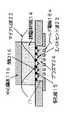
以上のように構成されたプラズマ処理装置について、その動作を図5を中心に説明する。まず、真空容器31を0.1Pa・以下の真空度まで真空排気し、アルゴンをガス導入口33から真空容器31内に導入して、プラズマ点火圧力である10Pa程度に調圧する。次に、電磁波源39から発振された2.45GHz・のマイクロ波40を、誘電体板38(ここでは厚さ10mmのパイレックスガラス)の内部に伝搬させ、第1導体板35と第2導体板37の間で反射させる。このとき開口36の直径がマイクロ波40の波長(12.4cm ・)よりかなり短いので、開口36を通してZ方向へマイクロ波40が伝搬することができずに、電磁界が指数関数的に減衰し減衰方向には波の形をとらないエバネセント波41を発生させる。図6には誘電体板を円板とした場合の電磁界シミュレーション結果を示す。減衰しながら開口径程度に電磁界が真空容器31側に漏れだしているのが分かる。この電磁界により、真空容器31に設置されたテスラコイル(図示せず)のトリガー放電を一時的に作用させると被処理基板32上にアルゴンプラズマ42を発生させることができる。その後、ガス圧力を調整して、プラズマ処理を行うことができる。
【0026】
マイクロ波のパワーを100Wとした場合には、アルゴンガス圧力1Paで、
3×10¹¹ (個/cm3)のプラズマ密度を得ることができた。また、0.01Paまで安定なプラズマを維持することができた。従来の表面波プラズマ処理装置の放電維持ガス圧力が数Pa程度で、そのときのプラズマ密度が1010個/cm3台であったので、プラズマ密度、放電維持ガス圧力ともに向上している。
【0027】
この結果から明らかなように、本実施の形態によるプラズマ処理装置はプラズマ処理においても、低ガス圧力領域で高速処理が可能となる。
【0028】
(実施の形態3)
以下本発明の第3の実施の形態について図面を参照しながら説明する。この第3の実施の形態では、第1導体板に複数の開口を設けた多孔板を用いることにより、更に大面積での均一性を向上させ、かつ、均一性に対する装置の制御性も向上させることができる。図7は本発明の第3の実施の形態を示す断面鳥瞰図である。図7において、51は第2の実施の形態の第1導体板37の開口36を複数個設けて多孔板にした第1導体板であり、その他のものは第2の実施の形態の構成と同様なものである。 以上のような構成によれば、電磁波源52から発振された2.45GHz・のマイクロ波(図示せず)を、誘電体板53(ここでは厚さ10mmのパイレックスガラス)の内部に伝搬させ、第1導体板51と第2導体板54の間で反射させると、第1導体板51に、たとえば径1.7mm・の開口55を複数個開け開口率45%・にすることにより、個々の孔からエバネセント波56を発生させることができる。エバネセント波56は均質な表面波を形成し、プラズマ57を発生させる。開口径と間隔を最適化することにより、大面積に均一なプラズマ処理が行えることなる。
【0029】
(実施の形態4)
以下本発明の第4の実施の形態について図面を参照しながら説明する。この第4の実施の形態は、マイクロ波の伝搬路として矩形導波管を用いることにより、更に低損失で電磁波の電力をプラズマに供給することができるようにしたものである。図8は本発明の第4の実施の形態を示す断面図である。図8において、61は第3の実施の形態の第1導体板51と第2導体板54を一体化した多孔矩形導波管であり、また、第3の実施の形態の電磁波源52を発振器62と矩形導波管63の組み合わせとし、その他のものは第3の実施の形態の構成と同様なものである。
【0030】
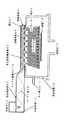
以上のような構成によれば、発振器62から発振された、たとえば2.45GHz・のマイクロ波65は、矩形導波管63(ここでは内壁寸法109.22mm×54.16mm )を経由して、一方がふたをされた多孔矩形導波管61(ここでは内壁寸法200mm・×25mm)の中に挿入された誘電体板66(ここでは厚さ25mmのパイレックスガラ・・ス)の内部に伝搬させ、多孔矩形導波管61の内部で反射させると、多孔矩形導波管61の一側面に、たとえば径1.7mm・の開口67を複数個開け開口率45%・にすることにより、個々の孔からエバネセント波68を発生させることができる。エバネセント波68は均質な表面波を形成し、プラズマ69を発生させる。多孔矩形導波管61のマイクロ波導入口70に対向する側面は短絡終端71であり、矩形導波管63の短絡終端72とでマイクロ波65の定在波を生成し、低損失のマイクロ波伝搬によりエバネセント波68を発生させることができ、効率よく大面積に均一なプラズマ処理が行えることになる。
【0031】
(実施の形態5)
以下本発明の第5の実施の形態について図面を参照しながら説明する。この第5の実施の形態は、第1導体板と第2導体板の両方を多孔板にすることにより、更にプラズマ処理の速度を向上させることができるようにしたものである。図9は本発明の第5の実施の形態を示す断面図である。図9において、81は第3の実施の形態の第2導体板54にも開口84を設けて得られた両面多孔板型矩形導波管である。その他の部分は第3の実施の形態の構成と同様なものであり、82は電磁波源、83は誘電体、85a、85bは基板、86は真空容器、87はガス導入口である。誘電体83の上下両側に開口84が設けられているため、図9中上方へも、下方へもエバネセント波を出力させることができ、プラズマ処理をする場合に、両面多孔板型矩形導波管81の上下両側に基板85a、85bを設置して一度に加工することが出来るから、作業能率を向上させることができる。
【0032】
(実施の形態6)
以下本発明の第6の実施の形態について図面を参照しながら説明する。この第6の実施の形態は、多孔を円筒の側面に設けることにより、更にプラズマ処理の速度を向上させることができるようにしたものである。図10は本発明の第6の実施の形態を示す断面鳥瞰図である。図10において、開口84を有する第1導体板93と誘電体94と第2導体板95は、第3の実施の形態の多孔板51と誘電体板53と第2導体板54を筒状にし、第1導体板93と第2導体板95との間に電磁波源96を接続したものであり、その他の部分は第3の実施の形態の構成と同様なものである。このような構成にすることにより、より密度の高いプラズマを発生させることができ、プラズマ処理をする場合の能率を上げることができる。
【0033】
【発明の効果】
以上説明したように本発明は、真空容器に接続され、第1の導体と空隙をもって対向し設置してある第2の導体と、その空隙に詰めた誘電体と、誘電体内に電磁波を伝送させる手段と、第1の導体に前記電磁波の波長より短い径の開口を設け、この開口から漏れ出てくる電磁波で、均一高密度にプラズマを発生させることができ、大面積の基板でも均一に処理することができる。また、均一性に対する装置の制御性も向上することができる優れたプラズマ処理装置を実現するものである。
【図面の簡単な説明】
【図1】本発明の第1の実施の形態におけるイオン源の断面鳥瞰図。
【図2】本発明の第1の実施の形態におけるイオン源の断面図。
【図3】本発明の第1の実施の形態におけるイオン源の動作原理図。
【図4】本発明の第2の実施の形態におけるプラズマ処理装置の断面図。
【図5】本発明の第2の実施の形態におけるプラズマ処理装置の動作原理図。
【図6】本発明の第2の実施の形態におけるプラズマ処理装置のシミュレーション図。
【図7】本発明の第3の実施の形態におけるプラズマ処理装置の断面鳥瞰図。
【図8】本発明の第4の実施の形態におけるプラズマ処理装置の断面図。
【図9】本発明の第5の実施の形態におけるプラズマ処理装置の断面図。
【図10】本発明の第6の実施の形態におけるプラズマ処理装置の断面鳥瞰図。
【図11】従来例におけるプラズマ発生装置の断面図。
【符号の説明】
51 第1導体板
52 電磁波源
53 誘電体板
54 第2導体板
55 開口
56 エバネセント波
57 プラズマ[0001]
[Industrial application fields]
The present invention relates to a plasma source used in a thin film forming process for semiconductors, liquid crystal panels, solar cells, etc., an etching process for forming a fine pattern, and a surface cleaning process, an ion source using the plasma source, and a plasma processing apparatus. It is.
[0002]
[Prior art]
2. Description of the Related Art In recent years, efforts have been actively made to realize high-speed, high-quality, and large-area processing in order to increase the functionality of plasma processing apparatuses and reduce processing costs. One of them is a plasma processing apparatus using surface waves. For example, K.K. Komachi, Journal of Vacuum Science and Technology A, Vol. 12, p. 769, 1994 (K. Komachi, Journal of Vacuum Science & Technology A, Vol. 12, p. 769 (1994)), etc., as described below, a method of introducing a microwave into a dielectric plate on a conductor. A surface wave excitation type plasma processing apparatus has been proposed.
[0003]
An example of such a conventional plasma processing apparatus is shown in FIG. FIG. 11 shows a cross-sectional view of a reaction chamber of a conventional plasma processing apparatus. In FIG. 11, reference numeral 1 denotes a vacuum vessel that is equipped with vacuum evacuation means and can hold a vacuum, and forms a discharge space. 2 is a substrate to be processed, 3 is an exhaust port, 4 is a gas introduction port, 5 is a rectangular waveguide that propagates microwaves, 6 is a conductor plate continuous with the rectangular waveguide, and 7 is partially inserted into the waveguide The dielectric plate 8 attached to the conductor plate is a glass plate for maintaining a vacuum secret, and a gap 9 is provided between the dielectric plate and the glass plate.
[0004]
The operation of the conventional plasma processing apparatus configured as described above will be described below. First, a gas such as argon or oxygen is introduced into the vacuum container 1 through the gas inlet 4 by about 30 Pa (Pascal). Thenwe provide
[0005]
[Problems to be solved by the invention]
However, in the above conventional configuration, it is difficult to maintain the plasma at low gas pressure because the intensity of the evanescent wave is weak, and the intensity distribution of the plane wave directly reflects the plasma density distribution, so the uniformity is poor and the substrate has a large area. However, it has a problem that it is difficult to apply.
[0006]
The present invention solves the above-mentioned conventional problems, and an object of the present invention is to provide a plasma processing apparatus capable of generating high-density plasma in a low gas pressure region and processing even a large area substrate.
[0007]
[Means for solving problems]
To achieve this object, the present invention provides a plasma generation chamber for generating plasma, a waveguide formed by using a first conductor and a second conductor adjacent to the plasma generation chamber, and the first A dielectric for propagating electromagnetic waves inserted between the first conductor and the second conductor so as to be in contact with both at least a portion of the first conductor and the portion of the second conductor facing the first conductor; A plasma source, wherein either one of the first conductor and the second conductor has a connection portion with the plasma generation chamber, and the connection portion has a diameter shorter than the wavelength of the electromagnetic wave. It has an opening, der which the electromagnetic wave is configured to generate plasma in the plasma generation chamber byan evanescent wave generated in the plasma generating chamber side through the opening by propagating through the dielectric .
According to another aspect of the present invention, there is provided a plasma generation chamber that generates plasma, a waveguide that is disposed at least partially in the plasma generation chamber and is formed using a first conductor and a second conductor, and the first A dielectric for propagating electromagnetic waves inserted between the first conductor and the second conductor so as to be in contact with both at least a part of the conductor of the second conductor and the portion of the second conductor facing the conductor; A plasma source, wherein one or both of the first conductor and the second conductor have a connection portion with the plasma generation chamber, and the connection portion is based on the wavelength of the electromagnetic wave. has an opening of a short diameter, the electromagnetic wave is configured to generate plasma in the plasma generation chamber byan evanescent wave generated in the plasma generating chamber side through the opening by propagating through the dielectric It is intended.
[0008]
With this configuration, the evanescent wave generated from the opening can change the electric field strength distribution and the penetration depth according to the opening diameter, and the large area uniformity of the electromagnetic field distribution can be improved by optimizing the arrangement of the opening. In addition, high-density and uniform plasma can be generated by a strong electric field even at low gas pressure, and even a large-area substrate can be uniformly processed at high speed.
[0009]
Another aspect of the present invention is that a means for generating an ion beam by applying a voltage to plasma generated in a plasma generation chamber is provided.
[0010]
DETAILED DESCRIPTION OF THE INVENTION
The invention according to claim 1 of the present invention includes a plasma generation chamber that generates plasma, a waveguide that is adjacent to the plasma generation chamber and that is formed using a first conductor and a second conductor, and A dielectric that is inserted between the first conductor and the second conductor so as to contact both at least a portion of the first conductor and the portion of the second conductor that opposes the first conductor; , Wherein either one of the first conductor and the second conductor has a connection portion with the plasma generation chamber, and the connection portion is shorter than the wavelength of the electromagnetic wave. has an opening diameter, said electromagnetic wave is a plasma source for generating plasma in the plasma generation chamber byan evanescent wave generated in the plasma generating chamber side through the opening by propagating through the dielectric, the open It has the effect of generating a plasma in the plasma generation chamber by an electromagnetic wave transmitted through the is applied to the gas of the plasma generating chamber.
[0011]
According to a second aspect of the present invention, there is provided a plasma generation chamber for generating plasma, and a waveguide formed by using at least a part of the plasma generation chamber and the first conductor and the second conductor. An electromagnetic wave is inserted between the first conductor and the second conductor so as to be in contact with both the tube and at least a part of the first conductor and the portion of the second conductor opposite thereto. A plasma source having a propagating dielectric, wherein one or both of the first conductor and the second conductor have a connection with the plasma generation chamber, and the connection of generating plasma has an opening of less diameter than the wavelength of the electromagnetic wave, the plasma generating chamber byan evanescent wave generated in the plasma generating chamber side through the opening by the electromagnetic wave propagating through the dielectric That a plasma source, has the effect of generating a plasma in the plasma generation chamber by an electromagnetic wave transmitted through the aperture is applied to the plasma generation chamber of a gas.
[0012]
According to a third aspect of the present invention, in the plasma source according to the first or second aspect, the first conductor and the second conductor are constituted by a cylindrical member arranged coaxially.
[0013]
According to a fourth aspect of the present invention, in the plasma source according to any one of the first to third aspects, the first conductor and / or the second conductor has a plurality of openings. .
[0016]
According to afifth aspect of the present invention, in the plasma source according to any one of the first tofourth aspects, the electromagnetic wave is a microwave.
[0018]
According to asixth aspect of the present invention, there is provided an electrode for generating an ion beam by applying a voltage to the plasma generated in the plasma generation chamber with respect to the plasma source according to any one of the first tofifth aspects. , Provided adjacent to the plasma generation chamber.
[0019]
According to aseventh aspect of the present invention, in the plasma source according to any one of the first tofifth aspects, the plasma generation chamber is a vacuum vessel provided with a vacuum evacuation means. The substrate to be processed is installed so that plasma processing is possible. The electromagnetic wave leaking from the opening can generate plasma uniformly and with high density, and even a large area substrate can be processed uniformly. It has the action.
[0020]
(Embodiment 1)
Hereinafter, a first embodiment of the present invention will be described with reference to the drawings. 1 and 2 are a cross-sectional bird's-eye view and a cross-sectional view, respectively, of an ion beam source (hereinafter referred to as “ion source”) using the plasma source according to the first embodiment of the present invention. 1 and 2, reference numeral 11 denotes a semi-coaxial cavity, which is an outer conductor (for example, inner diameter 76.9 mm, length 152.3 mm) 11a corresponding to the first conductor, and a central conductor (for example, the second conductor) The outer diameter is 33.4 mm and the length is 132.3 mm.) 11 b, and is supported by a Teflon disk 12. An N-type connector 13 is attached to one of the semi-coaxial cavities 11, and a dielectric disk 14 is installed at the end of the other central conductor 11b. The dielectric disk 14 is made of, for example, Pyrex glass having a diameter of 52 mm and a thickness of 10 mm. One plane of the dielectric disk 14 is in contact with the end surface of the central conductor 11b, which is the secondconductor , and the other one is in contactwith the outer conductor 11a, which is the firstconductor. The contacting outer conductor 11a is a perforated plate 15 (opening) . The perforated plate 15 is made of, for example, a stainless plate having a diameter of 40 mm and a thickness of 0.5 mm, and 169
[0021]
An
[0022]
The case where the ion source configured as described above is operated as an ion beam source will be described with reference to FIG. An ionized gas can flow into the
[0023]
When argon is used as the ionized gas, for example, a disk-shaped plasma 24 is generated in the cylindrical
[0024]
(Embodiment 2)
Hereinafter, a second embodiment of the present invention will be described with reference to the drawings. FIG. 4 is a cross-sectional view showing a plasma processing apparatus according to the second embodiment of the present invention. In FIG. 4, reference numeral 31 denotes a vacuum container that constitutes a plasma generation chamber and has a vacuum evacuation means, 32 is a substrate to be processed, 33 is a substrate to be processed, 33 is a gas inlet, 34 is an exhaust outlet, and 35 is a part of the side wall of the vacuum container. The first conductive plate connected as is provided with an opening 36. Here, a hole with a diameter of 40 mm is made. Reference numeral 37 denotes a second conductor plate that is placed opposite to the first conductor plate with a gap, and reference numeral 38 denotes a dielectric plate packed in the gap between the first conductor plate and the second conductor plate. Reference numeral 39 denotes an electromagnetic wave source for transmitting an electromagnetic wave into the dielectric plate 38. Here, a microwave (frequency 2.45 GHz) supplied by a coaxial line is used.
[0025]
The operation of the plasma processing apparatus configured as described above will be described with reference to FIG. First, the vacuum vessel 31 is evacuated to a degree of vacuum of 0.1 Pa · or less, and argon is introduced into the vacuum vessel 31 from the gas inlet 33 to adjust the plasma ignition pressure to about 10 Pa. Next, the 2.45 GHz · microwave 40 oscillated from the electromagnetic wave source 39 is propagated inside the dielectric plate 38 (here, Pyrex glass having a thickness of 10 mm), and the first conductor plate 35 and the second conductor plate 37. Reflect between. At this time, since the diameter of the opening 36 is considerably shorter than the wavelength (12.4 cm 2) of the microwave 40, the microwave 40 cannot propagate in the Z direction through the opening 36, and the electromagnetic field attenuates exponentially and attenuates. An evanescent wave 41 that does not take the form of a wave is generated in the direction. FIG. 6 shows the electromagnetic field simulation results when the dielectric plate is a disc. It can be seen that the electromagnetic field leaks to the vacuum container 31 side to the extent of the opening diameter while being attenuated. When the trigger discharge of a Tesla coil (not shown) installed in the vacuum vessel 31 is temporarily acted on by this electromagnetic field, the argon plasma42 can be generated on the substrate 32 to be processed. Thereafter, the plasma pressure can be adjusted by adjusting the gas pressure.
[0026]
When the microwave power is 100 W, the argon gas pressure is 1 Pa.
A plasma density of 3 × 10¹¹ (pieces / cm3 ) could be obtained. Moreover, a stable plasma could be maintained up to 0.01 Pa. Since the discharge sustaining gas pressure of the conventional surface wave plasma processing apparatus is about several Pa and the plasma density at that time is 1010 / cm3 , both the plasma density and the discharge maintaining gas pressure are improved.
[0027]
As is clear from this result, the plasma processing apparatus according to the present embodiment can perform high-speed processing in a low gas pressure region even in plasma processing.
[0028]
(Embodiment 3)
Hereinafter, a third embodiment of the present invention will be described with reference to the drawings. In the third embodiment, by using a perforated plate having a plurality of openings in the first conductor plate, the uniformity in a larger area is further improved, and the controllability of the apparatus with respect to the uniformity is also improved. be able to. FIG. 7 is a cross-sectional bird's-eye view showing a third embodiment of the present invention. In FIG. 7, reference numeral 51 denotes a first conductor plate which is a perforated plate provided with a plurality of openings 36 of the first conductor plate 37 of the second embodiment, and the others are the same as the configuration of the second embodiment. It is similar. According to the above configuration, the 2.45 GHz · microwave (not shown) oscillated from the electromagnetic wave source 52 is propagated inside the dielectric plate 53 (here, Pyrex glass having a thickness of 10 mm). When reflected between the first conductor plate 51 and the second conductor plate 54, for example, by opening a plurality of openings 55 having a diameter of 1.7 mm in the first conductor plate 51 so that the opening ratio is 45%. An evanescent wave 56can be generated. The evanescent wave 56 forms a uniform surface wave and generates a plasma 57. By optimizing the aperture diameter and interval, a uniform plasma treatment can be performed over a large area.
[0029]
(Embodiment 4)
Hereinafter, a fourth embodiment of the present invention will be described with reference to the drawings. In the fourth embodiment, a rectangular waveguide is used as a microwave propagation path, so that the power of electromagnetic waves can be supplied to the plasma with even lower loss. FIG. 8 is a cross-sectional view showing a fourth embodiment of the present invention. In FIG. 8, 61 is a porous rectangular waveguide in which the first conductor plate 51 and the second conductor plate 54 of the third embodiment are integrated, and the electromagnetic wave source 52 of the third embodiment is an oscillator. The combination of 62 and the rectangular waveguide 63 is the same as that of the third embodiment.
[0030]
According to the above configuration, the microwave 65 of 2.45 GHz, for example, oscillated from the oscillator 62 passes through the rectangular waveguide 63 (in this case, the inner wall size is 109.22 mm × 54.16 mm), one of which is covered. Is propagated inside a dielectric plate 66 (here, Pyrex Gala, which has a thickness of 25 mm) inserted into a perforated rectangular waveguide 61 (in this case, an inner wall size of 200 mm · × 25 mm) When reflected inside the waveguide 61, an evanescent wave is generated from each hole by opening a plurality of openings 67 having a diameter of 1.7 mm, for example, on one side surface of the porous rectangular waveguide 61 so that the opening ratio is 45%. 68can be generated. The evanescent wave 68 forms a uniform surface wave and generates a plasma 69. Side opposite to the microwave introduction port 70 of the perforated rectangular waveguide 61 are short-circuited end 71, to generate a standingmicrowave 65 and the short-circuit end 72 of the rectangular waveguide 63, a low-loss microwave propagation As a result, the evanescent wave 68 can be generated, and a uniform plasma treatment can be efficiently performed over a large area.
[0031]
(Embodiment 5)
Hereinafter, a fifth embodiment of the present invention will be described with reference to the drawings. In thefifth embodiment, both the first conductor plate and the second conductor plate are perforated plates, so that the plasma processing speed can be further improved. FIG. 9 is a cross-sectional view showing afifth embodiment of the present invention. In FIG. 9, reference numeral 81 denotes a double-sided perforated plate type rectangular waveguide obtained by providing an opening 84 in the second conductor plate 54 of the third embodiment. The other parts are the same as those of the third embodiment, in which 82 is an electromagnetic wave source, 83 is a dielectric, 85a and 85b are substrates, 86 is a vacuum vessel, and 87 is a gas inlet. Since the openings 84 are provided on both upper and lower sides of the dielectric 83, an evanescent wave can be output both upward and downward in FIG. 9, and when performing plasma processing, a double-sided porous plate rectangular waveguide Since the substrates 85a and 85b can be installed on both the upper and lower sides of the 81 and processed at a time, work efficiency can be improved.
[0032]
(Embodiment 6)
Hereinafter, a sixth embodiment of the present invention will be described with reference to the drawings. In the sixth embodiment, the speed of the plasma processing can be further improved by providing a hole on the side surface of the cylinder. FIG. 10 is a cross-sectional bird's-eye view showing a sixth embodiment of the present invention. In FIG. 10, a first conductor plate 93, a dielectric 94, and a second conductor plate 95 having an opening 84 are formed by forming the porous plate 51, the dielectric plate 53, and the second conductor plate 54 of the third embodiment into a cylindrical shape. The electromagnetic wave source 96 is connected between the first conductor plate 93 and the second conductor plate 95, and the other parts are the same as in the configuration of the third embodiment. By adopting such a configuration, it is possible to generate plasma with higher density, and it is possible to increase the efficiency when performing plasma processing.
[0033]
【The invention's effect】
As described above, the present invention is connected to a vacuum vessel, and is configured to transmit the electromagnetic wave into the second conductor, the second conductor disposed opposite to the first conductor with the gap, the dielectric packed in the gap, and the dielectric. The first conductor is provided with an opening having a diameter shorter than the wavelength of the electromagnetic wave, and the electromagnetic wave leaking from the opening can generate plasma uniformly and with high density, and even a large-area substrate can be processed uniformly. can do. In addition, an excellent plasma processing apparatus capable of improving the controllability of the apparatus with respect to uniformity is realized.
[Brief description of the drawings]
FIG. 1 is a cross-sectional bird's-eye view of an ion source according to a first embodiment of the present invention.
FIG. 2 is a cross-sectional view of an ion source according to the first embodiment of the present invention.
FIG. 3 is an operation principle diagram of the ion source according to the first embodiment of the present invention.
FIG. 4 is a cross-sectional view of a plasma processing apparatus in a second embodiment of the present invention.
FIG. 5 is an operation principle diagram of a plasma processing apparatus in a second embodiment of the present invention.
FIG. 6 is a simulation diagram of a plasma processing apparatus according to a second embodiment of the present invention.
FIG. 7 is a cross-sectional bird's-eye view of a plasma processing apparatus according to a third embodiment of the present invention.
FIG. 8 is a cross-sectional view of a plasma processing apparatus in a fourth embodiment of the present invention.
FIG. 9 is a cross-sectional view of a plasma processing apparatus in a fifth embodiment of the present invention.
FIG. 10 is a cross-sectional bird's-eye view of a plasma processing apparatus in a sixth embodiment of the present invention.
FIG. 11 is a cross-sectional view of a conventional plasma generator.
[Explanation of symbols]
51 First Conductor Plate 52 Electromagnetic Wave Source 53 Dielectric Plate 54 Second Conductor Plate 55 Opening 56 Evanescent Wave 57 Plasma
Claims (7)
Translated fromJapanesePriority Applications (1)
| Application Number | Priority Date | Filing Date | Title |
|---|---|---|---|
| JP04942097AJP3647592B2 (en) | 1997-03-04 | 1997-03-04 | Plasma source, ion source using the same, and plasma processing apparatus |
Applications Claiming Priority (1)
| Application Number | Priority Date | Filing Date | Title |
|---|---|---|---|
| JP04942097AJP3647592B2 (en) | 1997-03-04 | 1997-03-04 | Plasma source, ion source using the same, and plasma processing apparatus |
Publications (2)
| Publication Number | Publication Date |
|---|---|
| JPH10247598A JPH10247598A (en) | 1998-09-14 |
| JP3647592B2true JP3647592B2 (en) | 2005-05-11 |
Family
ID=12830595
Family Applications (1)
| Application Number | Title | Priority Date | Filing Date |
|---|---|---|---|
| JP04942097AExpired - Fee RelatedJP3647592B2 (en) | 1997-03-04 | 1997-03-04 | Plasma source, ion source using the same, and plasma processing apparatus |
Country Status (1)
| Country | Link |
|---|---|
| JP (1) | JP3647592B2 (en) |
Families Citing this family (7)
| Publication number | Priority date | Publication date | Assignee | Title |
|---|---|---|---|---|
| JP2004200113A (en)* | 2002-12-20 | 2004-07-15 | Hamamatsu Kagaku Gijutsu Kenkyu Shinkokai | Microwave plasma generation device |
| JP2007258093A (en)* | 2006-03-24 | 2007-10-04 | National Univ Corp Shizuoka Univ | Microwave plasma generator |
| KR101041271B1 (en)* | 2009-08-21 | 2011-06-14 | 포항공과대학교 산학협력단 | Electron beam generator and electron beam generating method |
| JP6281934B2 (en)* | 2013-10-08 | 2018-02-21 | 国立大学法人 東京大学 | Dielectric protection mechanism in small microwave plasma source |
| JP6624833B2 (en)* | 2015-07-31 | 2019-12-25 | 東京エレクトロン株式会社 | Microwave plasma source and plasma processing apparatus |
| US9831066B1 (en)* | 2016-05-27 | 2017-11-28 | Mks Instruments, Inc. | Compact microwave plasma applicator utilizing conjoining electric fields |
| JP7174466B1 (en)* | 2022-09-05 | 2022-11-17 | 株式会社ニッシン | Plasma generator and plasma processing device |
- 1997
- 1997-03-04JPJP04942097Apatent/JP3647592B2/ennot_activeExpired - Fee Related
Also Published As
| Publication number | Publication date |
|---|---|
| JPH10247598A (en) | 1998-09-14 |
Similar Documents
| Publication | Publication Date | Title |
|---|---|---|
| KR100498584B1 (en) | Plasma Treatment Equipment and Plasma Treatment Methods | |
| JP3020580B2 (en) | Microwave plasma processing equipment | |
| KR100689037B1 (en) | micrewave resonance plasma generating apparatus and plasma processing system having the same | |
| CN101647101B (en) | Plasma process apparatus | |
| EP0264913B1 (en) | Plasma processing apparatus | |
| KR101880702B1 (en) | Microwave plasma generating device and method for operating same | |
| JP2570090B2 (en) | Dry etching equipment | |
| KR19990006564A (en) | Plasma processing equipment | |
| JP5522887B2 (en) | Plasma processing equipment | |
| JPH0834208B2 (en) | Plasma processing apparatus and method thereof | |
| JP3647592B2 (en) | Plasma source, ion source using the same, and plasma processing apparatus | |
| KR930011765B1 (en) | Microwave Plasma Generator | |
| JP2003068716A (en) | Plasma processing apparatus and processing method | |
| WO2001022465A1 (en) | Plasma source of linear ion beam | |
| JP2569019B2 (en) | Etching method and apparatus | |
| JPH08315998A (en) | Microwave plasma processing equipment | |
| JP3082331B2 (en) | Semiconductor manufacturing apparatus and semiconductor device manufacturing method | |
| JP2641450B2 (en) | Plasma processing equipment | |
| JPH01134926A (en) | Plasma producing source and plasma processor using the same | |
| JPH10294199A (en) | Microwave plasma processing equipment | |
| JP3491190B2 (en) | Plasma processing equipment | |
| JP2633849B2 (en) | Plasma processing equipment | |
| JP3208995B2 (en) | Plasma processing method and apparatus | |
| JP2675000B2 (en) | Plasma processing equipment | |
| JP2972507B2 (en) | Microwave plasma processing equipment |
Legal Events
| Date | Code | Title | Description |
|---|---|---|---|
| TRDD | Decision of grant or rejection written | ||
| A01 | Written decision to grant a patent or to grant a registration (utility model) | Free format text:JAPANESE INTERMEDIATE CODE: A01 Effective date:20050208 | |
| A61 | First payment of annual fees (during grant procedure) | Free format text:JAPANESE INTERMEDIATE CODE: A61 Effective date:20050209 | |
| R150 | Certificate of patent or registration of utility model | Free format text:JAPANESE INTERMEDIATE CODE: R150 | |
| FPAY | Renewal fee payment (event date is renewal date of database) | Free format text:PAYMENT UNTIL: 20080218 Year of fee payment:3 | |
| FPAY | Renewal fee payment (event date is renewal date of database) | Free format text:PAYMENT UNTIL: 20090218 Year of fee payment:4 | |
| FPAY | Renewal fee payment (event date is renewal date of database) | Free format text:PAYMENT UNTIL: 20100218 Year of fee payment:5 | |
| FPAY | Renewal fee payment (event date is renewal date of database) | Free format text:PAYMENT UNTIL: 20100218 Year of fee payment:5 | |
| FPAY | Renewal fee payment (event date is renewal date of database) | Free format text:PAYMENT UNTIL: 20110218 Year of fee payment:6 | |
| FPAY | Renewal fee payment (event date is renewal date of database) | Free format text:PAYMENT UNTIL: 20120218 Year of fee payment:7 | |
| FPAY | Renewal fee payment (event date is renewal date of database) | Free format text:PAYMENT UNTIL: 20130218 Year of fee payment:8 | |
| LAPS | Cancellation because of no payment of annual fees |