JP3645814B2 - Circulating aeration system for submerged thin film modules - Google Patents
Circulating aeration system for submerged thin film modulesDownload PDFInfo
- Publication number
- JP3645814B2 JP3645814B2JP2000575802AJP2000575802AJP3645814B2JP 3645814 B2JP3645814 B2JP 3645814B2JP 2000575802 AJP2000575802 AJP 2000575802AJP 2000575802 AJP2000575802 AJP 2000575802AJP 3645814 B2JP3645814 B2JP 3645814B2
- Authority
- JP
- Japan
- Prior art keywords
- flow rate
- aeration
- gas
- thin film
- seconds
- Prior art date
- Legal status (The legal status is an assumption and is not a legal conclusion. Google has not performed a legal analysis and makes no representation as to the accuracy of the status listed.)
- Expired - Lifetime
Links
- 238000005273aerationMethods0.000titleclaimsdescription209
- 239000010409thin filmSubstances0.000titleclaimsdescription97
- XLYOFNOQVPJJNP-UHFFFAOYSA-NwaterSubstancesOXLYOFNOQVPJJNP-UHFFFAOYSA-N0.000claimsabstractdescription77
- 239000012528membraneSubstances0.000claimsabstractdescription68
- 238000004140cleaningMethods0.000claimsabstractdescription12
- 238000005276aeratorMethods0.000claimsabstract15
- 239000012510hollow fiberSubstances0.000claimsdescription32
- 238000001914filtrationMethods0.000claimsdescription22
- 238000000034methodMethods0.000claimsdescription18
- 239000012466permeateSubstances0.000abstractdescription7
- 230000001052transient effectEffects0.000abstractdescription5
- 230000002401inhibitory effectEffects0.000abstract1
- 239000007787solidSubstances0.000description21
- QVGXLLKOCUKJST-UHFFFAOYSA-Natomic oxygenChemical compound[O]QVGXLLKOCUKJST-UHFFFAOYSA-N0.000description11
- 239000001301oxygenSubstances0.000description11
- 229910052760oxygenInorganic materials0.000description11
- 230000000694effectsEffects0.000description10
- 230000002829reductive effectEffects0.000description7
- 239000002351wastewaterSubstances0.000description7
- 238000012360testing methodMethods0.000description6
- 230000009286beneficial effectEffects0.000description5
- 238000010586diagramMethods0.000description5
- 230000035515penetrationEffects0.000description5
- 230000035699permeabilityEffects0.000description5
- 238000012545processingMethods0.000description5
- 230000003247decreasing effectEffects0.000description4
- 238000002474experimental methodMethods0.000description4
- 239000012530fluidSubstances0.000description4
- 239000007789gasSubstances0.000description4
- 244000005700microbiomeSpecies0.000description4
- 230000003204osmotic effectEffects0.000description4
- 238000011001backwashingMethods0.000description3
- 238000013461designMethods0.000description3
- 239000003651drinking waterSubstances0.000description3
- 235000020188drinking waterNutrition0.000description3
- 230000004907fluxEffects0.000description3
- 238000001471micro-filtrationMethods0.000description3
- 239000002352surface waterSubstances0.000description3
- 238000000108ultra-filtrationMethods0.000description3
- IJGRMHOSHXDMSA-UHFFFAOYSA-NAtomic nitrogenChemical compoundN#NIJGRMHOSHXDMSA-UHFFFAOYSA-N0.000description2
- 230000001133accelerationEffects0.000description2
- 230000001464adherent effectEffects0.000description2
- 230000005540biological transmissionEffects0.000description2
- 230000008859changeEffects0.000description2
- 238000004891communicationMethods0.000description2
- 239000010408filmSubstances0.000description2
- 238000007654immersionMethods0.000description2
- 238000001764infiltrationMethods0.000description2
- 230000008595infiltrationEffects0.000description2
- 239000007788liquidSubstances0.000description2
- 239000011148porous materialSubstances0.000description2
- 230000008569processEffects0.000description2
- 230000002441reversible effectEffects0.000description2
- 238000007665saggingMethods0.000description2
- 239000000126substanceSubstances0.000description2
- 238000004065wastewater treatmentMethods0.000description2
- CBENFWSGALASAD-UHFFFAOYSA-NOzoneChemical compound[O-][O+]=OCBENFWSGALASAD-UHFFFAOYSA-N0.000description1
- 101000916532Rattus norvegicus Zinc finger and BTB domain-containing protein 38Proteins0.000description1
- 238000009825accumulationMethods0.000description1
- 230000009471actionEffects0.000description1
- 125000002015acyclic groupChemical group0.000description1
- 238000013459approachMethods0.000description1
- 229910000278bentoniteInorganic materials0.000description1
- 239000000440bentoniteSubstances0.000description1
- SVPXDRXYRYOSEX-UHFFFAOYSA-NbentoquatamChemical compoundO.O=[Si]=O.O=[Al]O[Al]=OSVPXDRXYRYOSEX-UHFFFAOYSA-N0.000description1
- 235000013361beverageNutrition0.000description1
- 230000015572biosynthetic processEffects0.000description1
- 239000012141concentrateSubstances0.000description1
- 238000011109contaminationMethods0.000description1
- 238000005265energy consumptionMethods0.000description1
- 238000005516engineering processMethods0.000description1
- 230000007613environmental effectEffects0.000description1
- 239000000835fiberSubstances0.000description1
- 239000000706filtrateSubstances0.000description1
- 238000012423maintenanceMethods0.000description1
- 230000002906microbiologic effectEffects0.000description1
- 238000012986modificationMethods0.000description1
- 230000004048modificationEffects0.000description1
- 229910052757nitrogenInorganic materials0.000description1
- 238000012856packingMethods0.000description1
- 230000036961partial effectEffects0.000description1
- 230000000149penetrating effectEffects0.000description1
- 230000000737periodic effectEffects0.000description1
- 230000010363phase shiftEffects0.000description1
- 239000002244precipitateSubstances0.000description1
- 239000011347resinSubstances0.000description1
- 229920005989resinPolymers0.000description1
- 230000000630rising effectEffects0.000description1
- 239000010865sewageSubstances0.000description1
- 239000002689soilSubstances0.000description1
- 230000003068static effectEffects0.000description1
- 238000003756stirringMethods0.000description1
- 239000000725suspensionSubstances0.000description1
- 230000002459sustained effectEffects0.000description1
- 238000005406washingMethods0.000description1
- 238000009736wettingMethods0.000description1
Images


Classifications
- B—PERFORMING OPERATIONS; TRANSPORTING
- B01—PHYSICAL OR CHEMICAL PROCESSES OR APPARATUS IN GENERAL
- B01D—SEPARATION
- B01D65/00—Accessories or auxiliary operations, in general, for separation processes or apparatus using semi-permeable membranes
- B01D65/08—Prevention of membrane fouling or of concentration polarisation
- B—PERFORMING OPERATIONS; TRANSPORTING
- B01—PHYSICAL OR CHEMICAL PROCESSES OR APPARATUS IN GENERAL
- B01D—SEPARATION
- B01D61/00—Processes of separation using semi-permeable membranes, e.g. dialysis, osmosis or ultrafiltration; Apparatus, accessories or auxiliary operations specially adapted therefor
- B01D61/14—Ultrafiltration; Microfiltration
- B01D61/18—Apparatus therefor
- B—PERFORMING OPERATIONS; TRANSPORTING
- B01—PHYSICAL OR CHEMICAL PROCESSES OR APPARATUS IN GENERAL
- B01D—SEPARATION
- B01D63/00—Apparatus in general for separation processes using semi-permeable membranes
- B01D63/02—Hollow fibre modules
- B01D63/026—Wafer type modules or flat-surface type modules
- B—PERFORMING OPERATIONS; TRANSPORTING
- B01—PHYSICAL OR CHEMICAL PROCESSES OR APPARATUS IN GENERAL
- B01D—SEPARATION
- B01D63/00—Apparatus in general for separation processes using semi-permeable membranes
- B01D63/02—Hollow fibre modules
- B01D63/033—Specific distribution of fibres within one potting or tube-sheet
- B—PERFORMING OPERATIONS; TRANSPORTING
- B01—PHYSICAL OR CHEMICAL PROCESSES OR APPARATUS IN GENERAL
- B01D—SEPARATION
- B01D63/00—Apparatus in general for separation processes using semi-permeable membranes
- B01D63/02—Hollow fibre modules
- B01D63/04—Hollow fibre modules comprising multiple hollow fibre assemblies
- B01D63/043—Hollow fibre modules comprising multiple hollow fibre assemblies with separate tube sheets
- B—PERFORMING OPERATIONS; TRANSPORTING
- B01—PHYSICAL OR CHEMICAL PROCESSES OR APPARATUS IN GENERAL
- B01D—SEPARATION
- B01D65/00—Accessories or auxiliary operations, in general, for separation processes or apparatus using semi-permeable membranes
- B01D65/02—Membrane cleaning or sterilisation ; Membrane regeneration
- B—PERFORMING OPERATIONS; TRANSPORTING
- B01—PHYSICAL OR CHEMICAL PROCESSES OR APPARATUS IN GENERAL
- B01F—MIXING, e.g. DISSOLVING, EMULSIFYING OR DISPERSING
- B01F23/00—Mixing according to the phases to be mixed, e.g. dispersing or emulsifying
- B01F23/20—Mixing gases with liquids
- B01F23/23—Mixing gases with liquids by introducing gases into liquid media, e.g. for producing aerated liquids
- B01F23/231—Mixing gases with liquids by introducing gases into liquid media, e.g. for producing aerated liquids by bubbling
- B01F23/23105—Arrangement or manipulation of the gas bubbling devices
- B01F23/2312—Diffusers
- B01F23/23124—Diffusers consisting of flexible porous or perforated material, e.g. fabric
- B01F23/231241—Diffusers consisting of flexible porous or perforated material, e.g. fabric the outlets being in the form of perforations
- B01F23/231242—Diffusers consisting of flexible porous or perforated material, e.g. fabric the outlets being in the form of perforations in the form of slits or cut-out openings
- B—PERFORMING OPERATIONS; TRANSPORTING
- B01—PHYSICAL OR CHEMICAL PROCESSES OR APPARATUS IN GENERAL
- B01F—MIXING, e.g. DISSOLVING, EMULSIFYING OR DISPERSING
- B01F23/00—Mixing according to the phases to be mixed, e.g. dispersing or emulsifying
- B01F23/20—Mixing gases with liquids
- B01F23/23—Mixing gases with liquids by introducing gases into liquid media, e.g. for producing aerated liquids
- B01F23/2319—Methods of introducing gases into liquid media
- B—PERFORMING OPERATIONS; TRANSPORTING
- B01—PHYSICAL OR CHEMICAL PROCESSES OR APPARATUS IN GENERAL
- B01F—MIXING, e.g. DISSOLVING, EMULSIFYING OR DISPERSING
- B01F33/00—Other mixers; Mixing plants; Combinations of mixers
- B01F33/40—Mixers using gas or liquid agitation, e.g. with air supply tubes
- B01F33/406—Mixers using gas or liquid agitation, e.g. with air supply tubes in receptacles with gas supply only at the bottom
- B01F33/4062—Mixers using gas or liquid agitation, e.g. with air supply tubes in receptacles with gas supply only at the bottom with means for modifying the gas pressure or for supplying gas at different pressures or in different volumes at different parts of the bottom
- C—CHEMISTRY; METALLURGY
- C02—TREATMENT OF WATER, WASTE WATER, SEWAGE, OR SLUDGE
- C02F—TREATMENT OF WATER, WASTE WATER, SEWAGE, OR SLUDGE
- C02F1/00—Treatment of water, waste water, or sewage
- C02F1/44—Treatment of water, waste water, or sewage by dialysis, osmosis or reverse osmosis
- C—CHEMISTRY; METALLURGY
- C02—TREATMENT OF WATER, WASTE WATER, SEWAGE, OR SLUDGE
- C02F—TREATMENT OF WATER, WASTE WATER, SEWAGE, OR SLUDGE
- C02F1/00—Treatment of water, waste water, or sewage
- C02F1/44—Treatment of water, waste water, or sewage by dialysis, osmosis or reverse osmosis
- C02F1/444—Treatment of water, waste water, or sewage by dialysis, osmosis or reverse osmosis by ultrafiltration or microfiltration
- C—CHEMISTRY; METALLURGY
- C02—TREATMENT OF WATER, WASTE WATER, SEWAGE, OR SLUDGE
- C02F—TREATMENT OF WATER, WASTE WATER, SEWAGE, OR SLUDGE
- C02F3/00—Biological treatment of water, waste water, or sewage
- C02F3/02—Aerobic processes
- C02F3/12—Activated sludge processes
- C—CHEMISTRY; METALLURGY
- C02—TREATMENT OF WATER, WASTE WATER, SEWAGE, OR SLUDGE
- C02F—TREATMENT OF WATER, WASTE WATER, SEWAGE, OR SLUDGE
- C02F3/00—Biological treatment of water, waste water, or sewage
- C02F3/02—Aerobic processes
- C02F3/12—Activated sludge processes
- C02F3/1236—Particular type of activated sludge installations
- C02F3/1268—Membrane bioreactor systems
- C02F3/1273—Submerged membrane bioreactors
- C—CHEMISTRY; METALLURGY
- C02—TREATMENT OF WATER, WASTE WATER, SEWAGE, OR SLUDGE
- C02F—TREATMENT OF WATER, WASTE WATER, SEWAGE, OR SLUDGE
- C02F3/00—Biological treatment of water, waste water, or sewage
- C02F3/02—Aerobic processes
- C02F3/12—Activated sludge processes
- C02F3/20—Activated sludge processes using diffusers
- C02F3/201—Perforated, resilient plastic diffusers, e.g. membranes, sheets, foils, tubes, hoses
- B—PERFORMING OPERATIONS; TRANSPORTING
- B01—PHYSICAL OR CHEMICAL PROCESSES OR APPARATUS IN GENERAL
- B01D—SEPARATION
- B01D2313/00—Details relating to membrane modules or apparatus
- B01D2313/26—Specific gas distributors or gas intakes
- B—PERFORMING OPERATIONS; TRANSPORTING
- B01—PHYSICAL OR CHEMICAL PROCESSES OR APPARATUS IN GENERAL
- B01D—SEPARATION
- B01D2315/00—Details relating to the membrane module operation
- B01D2315/06—Submerged-type; Immersion type
- B—PERFORMING OPERATIONS; TRANSPORTING
- B01—PHYSICAL OR CHEMICAL PROCESSES OR APPARATUS IN GENERAL
- B01D—SEPARATION
- B01D2321/00—Details relating to membrane cleaning, regeneration, sterilization or to the prevention of fouling
- B01D2321/04—Backflushing
- B—PERFORMING OPERATIONS; TRANSPORTING
- B01—PHYSICAL OR CHEMICAL PROCESSES OR APPARATUS IN GENERAL
- B01D—SEPARATION
- B01D2321/00—Details relating to membrane cleaning, regeneration, sterilization or to the prevention of fouling
- B01D2321/18—Use of gases
- B—PERFORMING OPERATIONS; TRANSPORTING
- B01—PHYSICAL OR CHEMICAL PROCESSES OR APPARATUS IN GENERAL
- B01D—SEPARATION
- B01D2321/00—Details relating to membrane cleaning, regeneration, sterilization or to the prevention of fouling
- B01D2321/18—Use of gases
- B01D2321/185—Aeration
- B—PERFORMING OPERATIONS; TRANSPORTING
- B01—PHYSICAL OR CHEMICAL PROCESSES OR APPARATUS IN GENERAL
- B01F—MIXING, e.g. DISSOLVING, EMULSIFYING OR DISPERSING
- B01F23/00—Mixing according to the phases to be mixed, e.g. dispersing or emulsifying
- B01F23/20—Mixing gases with liquids
- B01F23/23—Mixing gases with liquids by introducing gases into liquid media, e.g. for producing aerated liquids
- B01F23/231—Mixing gases with liquids by introducing gases into liquid media, e.g. for producing aerated liquids by bubbling
- B01F23/23105—Arrangement or manipulation of the gas bubbling devices
- B01F23/2312—Diffusers
- B01F23/23126—Diffusers characterised by the shape of the diffuser element
- B01F23/231265—Diffusers characterised by the shape of the diffuser element being tubes, tubular elements, cylindrical elements or set of tubes
- C—CHEMISTRY; METALLURGY
- C02—TREATMENT OF WATER, WASTE WATER, SEWAGE, OR SLUDGE
- C02F—TREATMENT OF WATER, WASTE WATER, SEWAGE, OR SLUDGE
- C02F1/00—Treatment of water, waste water, or sewage
- C02F1/72—Treatment of water, waste water, or sewage by oxidation
- C02F1/74—Treatment of water, waste water, or sewage by oxidation with air
- C—CHEMISTRY; METALLURGY
- C02—TREATMENT OF WATER, WASTE WATER, SEWAGE, OR SLUDGE
- C02F—TREATMENT OF WATER, WASTE WATER, SEWAGE, OR SLUDGE
- C02F2209/00—Controlling or monitoring parameters in water treatment
- C02F2209/40—Liquid flow rate
- C—CHEMISTRY; METALLURGY
- C02—TREATMENT OF WATER, WASTE WATER, SEWAGE, OR SLUDGE
- C02F—TREATMENT OF WATER, WASTE WATER, SEWAGE, OR SLUDGE
- C02F2209/00—Controlling or monitoring parameters in water treatment
- C02F2209/44—Time
- Y—GENERAL TAGGING OF NEW TECHNOLOGICAL DEVELOPMENTS; GENERAL TAGGING OF CROSS-SECTIONAL TECHNOLOGIES SPANNING OVER SEVERAL SECTIONS OF THE IPC; TECHNICAL SUBJECTS COVERED BY FORMER USPC CROSS-REFERENCE ART COLLECTIONS [XRACs] AND DIGESTS
- Y02—TECHNOLOGIES OR APPLICATIONS FOR MITIGATION OR ADAPTATION AGAINST CLIMATE CHANGE
- Y02W—CLIMATE CHANGE MITIGATION TECHNOLOGIES RELATED TO WASTEWATER TREATMENT OR WASTE MANAGEMENT
- Y02W10/00—Technologies for wastewater treatment
- Y02W10/10—Biological treatment of water, waste water, or sewage
Landscapes
- Chemical & Material Sciences (AREA)
- Chemical Kinetics & Catalysis (AREA)
- Life Sciences & Earth Sciences (AREA)
- Engineering & Computer Science (AREA)
- Water Supply & Treatment (AREA)
- Hydrology & Water Resources (AREA)
- Environmental & Geological Engineering (AREA)
- Organic Chemistry (AREA)
- Biodiversity & Conservation Biology (AREA)
- Microbiology (AREA)
- Separation Using Semi-Permeable Membranes (AREA)
- Activated Sludge Processes (AREA)
Abstract
Description
Translated fromJapanese【0001】
(技術分野)
本発明は、液体の濾過に関し、より詳細には、曝気槽が生成する洗浄気泡を使用して浸漬型薄膜フィルタの薄膜の汚れを洗浄又は防ぐことに関する。
【0002】
(背景技術)
浸漬型薄膜は、固形物を包含する液体の処理に使用され、固形物の希薄な濾過液体と、固形物の多い濾過されない濃縮水とを生成する。例えば、浸漬型薄膜は、廃水から実質的に清潔な水を抽出したり、湖水や貯水池の水から飲料水を抽出するのに使用される。
薄膜は、通常、薄膜とその薄膜に取り付けられるヘッダを含むモジュール内に配置される。モジュールは、固形物を包含する水の入ったタンク内に浸漬される。膜間圧力は、薄膜壁間に亘って加えられ、濾過された水を薄膜壁を通って貫通させる。固形物は薄膜によって排除され、タンク水の中に残って微生物学的又は化学的に処理されるか、又は、タンクから排出される。
【0003】
気泡は、薄膜モジュールの下方に配置され、導管により送風機に接続された曝気槽を通ってタンクに送り込まれる。気泡は、タンク水の表面まで上昇し、タンク水を薄膜モジュール周辺に再循環させるエアリフトを作り出す。空気流量が有効範囲内の場合、上昇する気泡とタンク水とが薄膜を洗い流し攪拌して、タンク内の固形物が薄膜の細孔に付着するのを抑制する。更に、気泡からタンク水に酸素が移行され、廃水処理の場合には微生物が成長するための酸素が供給される。送風機は、送風機モータに加わる応力を最小にし、必要ならば微生物が成長するために必要な酸素を常時供給するために、一般に連続的に運転される。
【0004】
一般的な曝気システムにおいて更に洗浄が必要な場合、オペレータは、曝気槽への空気流量を増やす。しかし、この手法は、薄膜と送風機モータとに応力を加え、消費エネルギーが増えるため処理の運転コストが大幅に増加する。反対に、洗浄が比較的少なくてよい場合、オペレータは、通常、曝気槽への空気流量を減らす。しかし、この方法においては、空気流量が常に有効範囲を下回り、効率的な洗浄をもたらさない。別の方法として、オペレータによっては、空気を間欠的に供給することによって平均空気流量を減らす場合がある。この方法により、空気流量は有効範囲に入るが、その代わり、送風機の入り切りが頻繁になることにより摩耗が速くなる。多くの場合、そのような間欠運転により、送風機の保証は取り消される。
【0005】
通常の曝気システムの別の問題は、タンク水をタンク内でほぼ定常状態の再循環パターンで移動させることである。再循環パターンは、一般に、再循環タンク水と気泡とがタンク水に到達しない「デッドゾーン」を含む。これらデッドゾーンにある薄膜又はその一部は、効果的に洗浄されず、通常のタンク水よりも高濃度の固形物を持つ水中で運転される可能性がある。従って、これらの薄膜又はこれらの薄膜の影響する部分は、固形物ですぐに汚れる。
薄膜が動いて固形物を振り落とす又は固形物の捕捉を避けるために、中空繊維薄膜が若干のたるみを持って設置される場合、同様な問題がモジュールに発生する。タンク内のタンク水の動きは、たるんだ薄膜が、特に薄膜の端部近くでほぼ定常状態の位置をとるように助長し、それが繊維の有益な動きを妨害する。
【0006】
更に、現行曝気システムの別の問題は、曝気槽自体がある時間が経つとしばしば汚れることである。空気が供給されている間でさえも、曝気槽の孔の周縁付近の局所的な空気圧が低く、タンク水を曝気槽の中に浸透させる。例えば、逆洗や洗浄や保守手順のために曝気が時々停止される時、より多いタンク水が曝気システムに入り得る。曝気システムに入るタンク水の一部はそこで蒸発し、曝気システムに固形沈殿物を残す。特に廃水用途においては、沈殿した固形物が曝気システムの効率を著しく低下させるか、又は、オペレータに定期的に濾過作用を中断させ、曝気槽の洗浄又は交換をさせることになる。
【0007】
(発明の開示)
本発明の目的は、タンクのタンク水に浸漬される限外濾過及び微細濾過薄膜モジュールを曝気するのに使用し得る循環曝気システムを提供することである。循環曝気システムは、バルブセット及びバルブセット制御装置を使用して、空気供給装置を空気吐出しネットワークの複数の個別分岐に接続する。空気吐出しネットワークの個別分岐は、次に、薄膜モジュールの下方に置かれた曝気槽に接続される。空気供給装置は、初期の定常的な空気流を供給するように運転されるが、バルブセット及びバルブ制御装置は、初期空気流を分割して空気分配システムの個別の分岐に分配し、それにより、各々の個別分岐への空気流が高流量と低流量との間で繰り返し周期で交替する。
【0008】
1つに実施形態において、循環曝気システムは、各々が空気吐出しネットワークの個別分岐に付随する複数の濾過帯域に配置された薄膜モジュールに間欠曝気を準備するために使用される。循環曝気システムは、所定の時間、各々の濾過帯域に順に曝気を供給するように形成され、運転される。別の実施形態において、循環曝気システムは、薄膜モジュールのグループに強力な曝気を供給するために使用される。そのような実施形態の1つにおいて、循環曝気システムは、空気吐出しネットワークの分岐に高流量と低流量との間を120秒又はそれ以下の周期で交替して空気を供給するように形成され、運転される。別のそのような実施形態において、空気吐出しネットワークの第1分岐に付随する曝気槽は、空気吐出しネットワークの第2分岐に付随する曝気槽の間に点在する。高流量の空気流は、空気吐出しネットワークの第1及び第2分岐の間で120秒又はそれ以下の周期で交替する。
ここで、本発明の最良の実施形態は、添付図面を参照して以下に説明される。
【0009】
(発明を実施するための最良の形態)
一般的記述
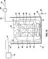
図1を参照すると、リアクタ10の一般的配置が示されている。本節での「リアクタ10」の記述は、いかなる特定実施形態の記述とも矛盾しない点まで、以下に述べる様々な実施形態にも一般に適用される。
リアクタ10は、タンク12を有しており、最初に、注入口16より供給される供給水14が満たされている。供給水14は、微生物、浮遊物質、又は、固形物と総称されることになる他の物質を包含し得る。一度タンクの中に入ると、供給水14は、特にリアクタが廃水処理に使用される場合、種々の固形物の増加した濃度を持ち得るタンク水18となる。
【0010】
1つ又はそれ以上の薄膜モジュール20は、タンクに装着され、1つ又はそれ以上の薄膜6の浸透側と流体連結する1つ又はそれ以上のヘッダ22を持つ。薄膜モジュール20の薄膜6の細孔サイズは、微細濾過又は限外濾過の範囲で、0.003と10ミクロンとの間のあることが好ましい。
ヘッダの形態を変えることにより、薄膜モジュール20は、種々のサイズ及び形態で利用可能である。例えば、薄膜6を中空の繊維とし、その内腔が少なくとも1つのヘッダ22と流体連結されるように1つ又はそれ以上のヘッダ22に埋め込まれてもよい。ヘッダ22は、どのような都合のよい形状でもよいが、通常は薄膜6に取り付けられる矩形又は円形面を持つ。別の方法としては、薄膜6は、一般に垂直方向に向けられ、間隔を置かれた1対の平らなシートであってもよく、ヘッダ22が全ての4つの側面上で、得られる内面と流体連結される。薄膜モジュール20は、1つ又はそれ以上の微細濾過又は限外濾過薄膜6を持つことができ、多くの薄膜モジュール20は互いに結合されてより大きな薄膜モジュール又はカセットを形成し得るが、そのような形態は、全て薄膜モジュール20と呼ばれることになる。
【0011】
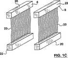
図1B、図1C、及び、図1Dは、矩形かせ8を有する好適な薄膜モジュール20を示す。各々の矩形かせ8において、中空繊維薄膜23が2つの対向するヘッダ22の間に保持される。各々の薄膜23の端部は、埋込樹脂によって囲まれ、薄膜23の外側とヘッダ22との間に水密な接続を生成し、同時に中空繊維薄膜23の内腔と少なくとも1つのヘッダ22との流体連結を保持している。矩形かせ8は、水平面に(図1B)、垂直面に(図1C)、又は、垂直面に水平に(図1D)向けることができる。複数の矩形かせ8は、通常、薄膜モジュール20で互いに結合される。
各々の矩形かせ8において単一列の中空繊維薄膜23が示されているが、標準的な矩形かせ8は、2センチメートルから10センチメートルの幅に大量の中空繊維薄膜23を有する。通常、中空繊維薄膜23の外径は0.4ミリメートルと4.0ミリメートルの間であり、10%及び40%の間の充填密度で埋め込まれる。中空繊維薄膜23の長さは、一般に400ミリメートルと1、800ミリメートルの間であり、0.1%から5%の間のたるみで取り付けられる。
【0012】
再度図1Aを参照すると、浸透の間、タンク12には、薄膜モジュール20の薄膜6の高さを超えるタンク水18が満たされている。浸透液24と呼ばれる濾過水は、膜間圧力の効果により薄膜モジュール20の薄膜6の壁面を通って流れ、ヘッダ22に集まって浸透液管路28を通り、浸透液排排出口26に搬送される。膜間圧力は、浸透液管路28に部分的真空を生成する浸透液ポンプによって作り出されることが好ましい。膜間圧力は、異なる薄膜の種類や適用例によって変動し得るが、通常、1キロパスカルと150キロパスカルとの間である。浸透液24はまた、周期的に薄膜モジュール20を通して逆方向に流され、薄膜モジュールを洗浄するのを補助してもよい。
【0013】
浸透の間、薄膜6は、タンク水18に残留している固形物を除去する。これらの固形物は、リアクタ10がバイオリアクタの場合には微生物による消化、又は、定期的にタンク12の排水、又は、タンク水18の一部を連続的に除去するなどを含むいくつかの方法で除去することができるが、後者の2つの方法は、タンク底部の排水管34にある排水バルブ32を開いて達成される。
曝気システム37は、空気吐出しシステム40により接続された1つ又はそれ以上の曝気槽38と、一般に1つ又はそれ以上の送風機でありタンク水で気泡36を発生する空気供給装置42への配分マニホルド51とを有する。曝気槽38は、キャップ曝気槽などの個別の曝気槽、又は、配分マニホルド51に取り付けられた管又は配分マニホルド51の一部にドリルで孔をあけただけのものなどを含む、様々なタイプがあり得る。気泡は、空気で作ることが好ましいが、必要であれば酸素又は酸素濃縮空気などの別の気体で作ってもよい。
【0014】
曝気槽38は、通常、薄膜モジュール20の下に置かれる。薄膜モジュール20が垂直な中空繊維薄膜23を有する矩形かせ8で作られている場合には、曝気槽38は、下部ヘッダの縁部近くに気泡を発生させるように置かれることが好ましい。垂直面に中空繊維薄膜23を有する矩形かせ8においては、曝気槽38は、垂直面のすぐ下の管路に気泡を発生させるように置かれることが好ましい。水平面に中空繊維薄膜23を有する矩形かせ8においては、曝気槽38は、平面下に均一に分散する気泡を発生させるように置かれることが好ましい。
【0015】
気泡36は、薄膜6を攪拌し、その付着物を抑制又は洗浄する。更に、気泡36はまた、薄膜モジュール20内又は近辺のタンク水18の局所密度を小さくしてエアリフト効果をもたらし、タンク水18を薄膜モジュール20を通り越して上方に流す。エアリフト効果によって再循環パターン46が起こり、タンク水18が薄膜モジュール20を通って上方に流れ、次に、タンクの側面又は他の部分に沿って下方に流れる。通常気泡36は、表面で破裂し、再循環パターンの下方に向かって流れる部分を通るタンク水18には従わない。タンク水18はまた、例えば注入口16から排水管34に向かう動きに従って流れ得るが、そのような流れが気泡36が生成する流れに優先することはない。
【0016】
気泡36の平均直径は、0.1と50ミリメートルとの間である。独立した大きな気泡36は、薄膜6の洗浄又は付着物の抑止にとってより効果的であると考えられているが、より小さい気泡36は、タンク水18に酸素を搬送するのにより効果的であり、また、各気泡36当たりの生成エネルギーがより少なくて済む。直径が3ミリメートルと20ミリメートルとの間、より好適には5ミリメートルと15ミリメートルとの間の気泡36は、多くの廃水適用例に使用するのに適している。上記範囲の気泡36により、タンク12の表面においてタンク水18から過度の気泡を生じさせることなく、薄膜6の洗浄が効果的に行われ、タンク水18に良好な酸素搬送をもたらす。飲料水を生成するため、又は、酸素搬送が不要な他の適用例のためにリアクタ10が使用される場合、5ミリメートルと25ミリメートルとの間の気泡が好適である。
【0017】
気泡36は、気泡36が空気圧、流量、及び、タンク水18の表面下の曝気槽38の深さなどの既知の要素に従って作られる曝気槽38の孔よりも大きい可能性がある。曝気槽38が地方自治体の処理作業に使用されるような大きなタンク12の底部近くに設置される場合、2ミリメートルと15ミリメートルとの間、好適には5ミリメートルと10ミリメートルとの間の孔を持つ曝気槽38を使用し得るであろう。供給される空気圧力(大気圧に対して)は、一般に、曝気槽38の水没深さでの水頭(約10キロパスカル毎メートル)と、曝気槽38を通る目標とする空気流量を得るのに必要な追加圧力とから決められる。曝気槽38の孔を横切って一般に5ミリメートルと100ミリメートルとの間、典型的には10ミリメートルと50ミリメートルとの間の圧力降下がある。曝気槽38の孔の底部下方に圧力降下と等しい距離に置かれる曝気システム37の部品は、少量のタンク水18が曝気システム37内にそれでもしみ込む可能性はあるが、空気供給装置42が作動している時には、通常、タンク水から防水されている。
【0018】
循環曝気槽
ここで図2を参照すると、バルブセット254に流体連結された空気供給装置242を有する循環曝気槽237が示され、バルブセット254は、バルブ制御装置256によって制御されている。バルブセット254は、複数の個別分岐を持つ空気吐出しネットワーク240と流体連結され、個別分岐の各々は、導管曝気槽238と流体連結された個別ヘッダ251に流体連結されている。ヘッダ251又は空気吐出しネットワークに対する適切な変更と共に、他のタイプの曝気槽も使用し得るが、導管曝気槽238が好適である。空気吐出しネットワーク240の第3分岐と第3ヘッダ251とが波線で表され、空気吐出しネットワーク240の個別分岐及びヘッダ251の数が2又はそれ以上であってもよいことを示すが、15を越えないことが好ましい。
【0019】
空気供給装置242は、一般に1つ又はそれ以上の送風機である加圧空気の供給源であり、循環曝気システムに初期流量の気体流を供給する。気体は、多くの場合空気であるが、酸素、酸素又はオゾン濃縮空気、又は、空気供給装置242が送風機に加えて酸素化又はオゾン化装置などを備えることになる場合は窒素でもよい。しかし、本明細書において「空気」という用語は、適切な気体のいずれをも指すものとする。空気供給装置242によって供給される空気量は、空気供給装置242が全ての導管曝気槽238に供給する量(以下に述べる)を合計することにより最適に決められる。空気供給装置242は、常時一定量の空気を供給することが好ましい。
バルブセット254及びバルブ制御装置256について、以下に更に詳細に説明される。しかし、一般的な観点において、バルブセット254及びバルブ制御装置256は、(a)空気供給装置242からの空気流量を空気吐出しネットワーク240の間で分岐し、ある時点において、いくつかの分岐がより多い流量の空気を受け取り、いくつかの分岐がより少ない流量の空気を受け取る、また、(b)多い及び少ない流量の空気を受け取る空気吐出しネットワーク240の分岐を繰り返し周期により切り替える。
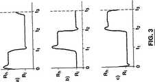
【0020】
図3に例が示されている。図3の各部分a)、b)、及び、c)において、Rhは多い流量を、Rlは少ない流量を示し、0からt3までの時間は、繰り返されるであろう周期を示す。周期は、3つの実質的に等しい時間間隔、0からt1、t1からt2、及び、t2からt3に分割される。これらの時間間隔の各々において、空気吐出しシステム240の1つの分岐とその付随する配分マニホルド251とは、Rhで空気を受け取り、一方、他は、Rlで空気を受け取る。同様に、空気吐出しシステム240の各分岐及びその付随する配分マニホルド251は、周期の1/3に対してRhで、また、周期の2/3に対してRlで空気を受け取る。
【0021】
以下に説明するバルブセット254の多くは、マニホルド251に対する空気流量の滑らかな変動を生み出すために使用できるが、変化が図3に示すように相当急激なことが好ましい。本発明者は、そのように急激な変化が異常に大きな気泡36の短時間の破裂を生み出し、洗浄又は付着物抑制にかなりの効果を持つようにみえることをに注目した。多くの場合、この急激な変化は、RhからRlに移行した直後に空気流量のスパイクを生み出し、それに対応する圧力サージを発生させる。この圧力サージは、循環曝気槽237の設計限限内に保たれるか、又は、適切な吹出バルブなどを設ける必要がある。
【0022】
マニホルド251又は空気吐出しネットワーク240の分岐に供給される空気の量は、多くの要因に左右されるが、導管曝気槽238に供給する空気流の見かけ速度に関連することが好ましい。空気流の見かけ速度は、標準条件(1気圧、25℃)における導管曝気槽238に対する空気流量を曝気の断面積で割ったものとして定義される。曝気の断面積は、導管曝気槽238によって効果的に曝気される面積を測定して決められる。高い流量(Rh)において、空気流の見かけ速度は、0.013メートル/秒と0.15メートル/秒との間が好ましい。飲料用途に使用される空気送風機の寸法は、この範囲の下限値に近く、一方、廃水用途の空気送風機の寸法は上限値に近いであろう。
Rlは、通常、Rhの半分未満であり、多くの場合、流れのないエア・オフ状態である。この範囲内において、少ない空気流量は、供給水14の質に影響される。エア・オフ状態が通常好ましいが、いくらかの量の供給水14の供給によって、低い流量における曝気の短時間の間においてさえ、中空繊維薄膜23は顕著に汚れる。これらの場合、少ない空気流量が大きい流量の半分に近づくと良好な結果が得られる。
【0023】
図4A、図4B、及び、図4Cを参照すると、バルブセット254とバルブ制御装置256の代わりの実施形態が示されている。図4Aにおいて、空気供給装置242は、好適にはボールバルブである三方バルブに空気を送風し、その2つの残っているオリフィスが2つのマニホルド251に接続されている。三方バルブ制御装置294は、マニホルド251の1つへの空気経路を開き、次に別の1つへの流路を開くという具合に交互に開く。好適には180度の位相のずれがあり、そのために1つのマニホルド251への空気経路が開く間、別のマニホルド251への経路は閉じる。三方バルブ292は、三方バルブ制御装置294上のレバー299にコネクタ298によって接続されたハンドル296によって機械的に作動することが可能であり、その場合、三方バルブ制御装置は、レバー299の回転に必要な速度で回転する駆動ユニットである。しかし、三方バルブ制御装置294は、三方バルブ292を急激に動かすために、より簡単に形成できるマイクロプロセッサとサーボ又はソレノイドとの組み合わせが好適である。
【0024】
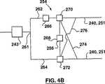
図4Bにおいて、空気供給装置242は、空気流を低流量管路262と高流量管路264に分割するコネクタ262内に空気を送る。低流量管路262中のバルブ266は、低流量管路262中の流量が好適には高流量管路264中の流量の半分未満であるように調整される。好適にはタイマ、マイクロプロセッサ、又は、次に述べるバルブに対して電気的又は機械的に結合する1つ又はそれ以上のモータである制御装置268は、電磁バルブ又は三方ボールバルブであり得る低圧バルブ270と、電磁バルブ又は三方ボールバルブであり得る高圧バルブ272とを制御し、そのため、第1の時間間隔(周期の第1の部分)の間、低流量管路中の空気がマニホルド251の1つに流れ、高流量管路中の空気が他のマニホルド251に流れる。第2の時間間隔(周期の第2の部分)の間、低圧バルブ270及び高圧バルブ272は、低流量管路262中の空気が交差導管274を通ってマニホルド251へ流れ、高流量管路264中の空気が逆交差導管276を通って別のマニホルドに流れるように制御される。
図4Cにおいて、空気供給装置242は、バルブ262によってマニホルド251に接続された送風機ヘッダ260内へ空気を送風する。各々のバルブ262は、通常電磁又はサーボモータである従属制御装置280によって制御される。従属制御装置は、本節及び以下に示す実施形態にて説明されるシステム作動に従ってバルブ262を開閉するようにプログラムされたマイクロプロセッサ282によって作動される。
【0025】
効率的な間欠曝気をもたらす循環曝気の使用
効率的な間欠曝気をもたらす循環曝気システム237の使用について、ここで以下の実施形態を参照して説明されるが、本発明はその実施形態に限定されないことを理解されたい。図5を参照すると、濾過タンク412中の6つの薄膜モジュール20(波線で示されている)に対する間欠曝気をもたらす用途の曝気システム237が示されている。濾過タンク412は、6つの薄膜モジュール20に対応して6つの濾過帯域(波線で示されている)を有する。別の方法として、濾過帯域は、1つ又はそれ以上の薄膜モジュールを各々有する分離されたタンクによって準備することができる。薄膜モジュール20は、比較的付着物のない、間欠曝気に適するような表面水の濾過に使用されるであろう。
【0026】
空気吐出しネットワーク240は、各々が濾過帯域中のヘッダ251に接続された6つの分岐を有する。各々のヘッダ251は、次に、通常薄膜モジュール20の下部に取り付けられたマニホルド曝気槽238に接続される。バルブセット254とバルブ制御装置256とは、空気供給装置242から空気吐出しネットワーク240へ7.5分周期で空気を供給するように形成及び作動され、高流量の空気が空気吐出しネットワーク240の各分岐に順に約75秒間供給される。空気吐出しネットワーク240の分岐が高流量で空気を受け入れていない間は、低流量で空気を受け入れる。従って、各々のヘッダ251は、7.5分毎に75秒間高流量で空気を受け入れる。しかし、空気供給装置242の作動は一定であり、1つのマニホルド251用の大きさの空気供給装置が、6つのそのようなマニホルドに供するために使用される。
【0027】
薄膜モジュール20が空気に曝されている間に薄膜モジュール20の逆洗が起こるように、薄膜モジュール20の逆洗も薄膜モジュール上で順々に行われることが好ましい。薄膜モジュール20は、各々の薄膜モジュール20がそれ自体の浸透ポンプ30とそれに付随する逆洗装置とによって処理される場合に最も簡単に逆洗できる。例えば大型の地方自治体のシステムにおいて、浸透及び逆洗装置は、一般に約8から11ML/日の能力に限定される。従って、中間の大きさの(すなわち、40ML/日の範囲)プラントは、個別に制御できる浸透及び逆洗装置セットにより供されるいくつかの薄膜モジュール20を持つであろう。あるプラントにおいては、逆洗が薄膜モジュール20上で順に行われ、曝気に関係なく浸透24の均一な供給が生み出される。
【0028】
例えば濁度0.3ntu、色度3.9tcuの供給水で実施された予備研究において、本発明者は、見かけ速度0.035メートル/秒の高流量での15分15秒毎の75秒間の曝気を用い、薄膜モジュールの良好な持続浸透性を達成できた。周期の残りの時間は、曝気を行わなかった。各々の周期において、薄膜モジュール20を通る浸透が15分、逆洗が15秒であった。曝気が75秒設定されたので、バックパルス前の曝気が30秒、バックパルス中の曝気、及び、バックパルス後の曝気が30秒あった。この試験が示唆するのは、循環曝気を各々のマニホルド251が付随する薄膜モジュール20の逆洗と一致するように設定する場合、約12個の薄膜モジュール20が、循環曝気システム237の一部としての単一空気供給装置242によって供給され得るということである。
【0029】
強力な曝気をもたらす循環曝気の使用
ここで、以下の実施形態に関連して強力な曝気をもたらす循環曝気槽237の使用について説明されるが、本発明はその実施形態に限定されないことを理解されたい。図6を参照すると、濾過容器512の2組の薄膜モジュール20(波線で示されている)の間で交替する曝気をもたらすのに使用される曝気システム237が示されている。濾過容器512はまた、2組の薄膜モジュール20に対応して2組の濾過帯域(同様に波線で示されている)を有する。別の方法として、濾過帯域は、各々のタンクに1つ又はそれ以上の薄膜モジュール20を有する別々のタンクで準備できるであろう。薄膜モジュール20は、強力な曝気が適する比較的付着物の多い表面水又は廃水を濾過するのに使用されるであろう。
【0030】
空気吐出しネットワーク240は、2つの個別の分岐を有し、各々が濾過帯域のヘッダ251に接続される。各々のヘッダ251は、次に、一般に薄膜モジュール20の下部に取り付けられる導管曝気槽238に接続される。バルブセット254とバルブ制御装置256とは、空気供給装置242から空気吐出しネットワーク240へ短い周期で空気を供給するように形成及び作動され、高流量の空気が空気吐出しネットワーク240の各分岐に半分の周期の間供給される。空気吐出しネットワーク240の分岐が高流量で空気を受け入れていない間は、低流量の空気を受け入れる。
【0031】
好適な総周期は、濾過容器512の深さ、薄膜モジュール20のデザイン、処理パラメータ、及び、処理される供給水14の条件によって変わり得るが、濾過容器512の深さが1メートルと10メートルとの間の一般的な地方自治体用タンクの場合、少なくとも10秒(最高流量で5秒間及び低減流量で5秒間)が好適である。最大120秒(最高流量で60秒間、低減流量で60秒間)の周期が有効であり得るが、濾過容器412が一般的な地方自治体用タンクの場合、60秒(最高流量で30秒間、低減流量で30秒間)を超えない周期が好ましい。
【0032】
そのように速い周期においては、タンク水18内で過渡的流れが発生すると本発明者は考えている。特に、空気流量がRlからRhに変化してタンク水18が加速される場合、エアリフト効果が生成又は強化される。しかし、そのすぐ後には、曝気とエアリフト効果とは急激に小さくなり、タンク水18が減速される。周期が非常に短いと、タンク水18は周期の大部分の間加速又は減速され、定常状態はほとんどなくなる。タンク水18に静止帯域が形成されるのが抑制され、中空繊維薄膜23の有益な動きが高められると考えられる。例えば、水平な中空繊維薄膜23は、図1B及び図1Dの矩形かせ8に示すように、定常状態曝気の下において、一般に下方に凹面の形状をしており、それらの端部において制限された動きをする。しかし、上記の循環曝気においては、中空繊維薄膜23の応力は周期的に解放され、ある場合には下方に流れる局所流が短時間の間発生し得る。水平な中空繊維薄膜23の端部は、より有益な動きをし、汚れが比較的遅い。この有益な効果は、過渡的流れの生成と関連している可能性があるので、タンクの深さ又は囲い板など、1組の導管曝気槽238上方の水柱の加速をもたらす要素は、前述の好適な周期を修正し得ると考えられる。
【0033】
水平流を促進する循環曝気の使用
タンク水18の水平流を促進する循環曝気の使用について、以下の実施形態に関連して説明されるが、本発明はその実施形態に限定されないことを理解されたい。図7を参照すると、処理タンク612の薄膜モジュール20を空気に曝すために使用される曝気槽237が示されている。薄膜モジュール20は、強力な曝気が適切である比較的付着物の多い表面水又は廃水を濾過するのに使用されるであろう。
空気吐出しネットワーク240は、2つの個別の分岐を有し、各々が単一濾過帯域にある2つの個別のヘッダ251に接続される。ヘッダ251は、区別する都合からヘッダ251a及び251bと称する。ヘッダ251は、ヘッダ251aに取り付けられた導管曝気槽238の間にヘッダ251bに取り付けられた導管曝気槽238が点在するように導管曝気槽238に接続される。そのような配置の1つが図7Aに示されるが、ヘッダ251aは、薄膜モジュール20の真下の導管曝気槽238に接続され、一方、ヘッダ251bは、薄膜モジュール20の下方及びその間に配置された水平にずらされた導管曝気槽238に接続される。ここで、図7B、図7C、及び、図7Dを参照すると、図7Aの実施形態の1組の変形が示されている。図7Bにおいて、ヘッダ251aと251bとは、薄膜モジュール20の下に配置された、水平にずらされた交替する導管曝気槽238に接続される。図7Cにおいて、ヘッダ251aと251bとは、交替する薄膜モジュール20の真下に配置された、水平にずらされた交替する導管曝気槽238に接続される。図7Dにおいて、ヘッダ251aと251bとは、交替する薄膜モジュール20の真下でその間に配置された、水平にずらされた交替する導管曝気槽238に接続される。これらの事例のいずれにおいても、より多くの薄膜モジュール20が使用される場合は、そのパターンが繰り返される。
【0034】
ヘッダ251aと251bとは、各々、バルブセット254に次に接続される空気吐出しネットワーク240の個別の分岐に接続される。バルブセット254とバルブ制御装置256とは、空気供給装置242から空気吐出しネットワーク240へ短い周期で空気を供給するように配置及び作動され、高流量の空気が空気吐出しネットワーク240の各分岐に半分の周期の間供給される。空気吐出しネットワーク240の分岐が高流量で空気を受け入れていない間は、低流量の空気を受け入れる。低流量とは、好適には高流量の半分か又はそれ以下の流量であり、条件が許せば、低流量は、エア・オフ状態であることが好ましい。
【0035】
総周期は、濾過容器512の深さ、薄膜モジュール20のデザイン、処理パラメータ、及び、処理される供給水14の条件によって変動し得るが、濾過容器412が深さ1メートルと10メートルとの間の一般的な地方自治体用タンクの場合、少なくとも2秒(最高流量で1秒、低減流量で1秒)で、120秒(最高流量で60秒、低減流量で60秒)未満であることが好ましい。しかし、周期の長さは、20秒と40秒との間が好適である。10秒以下の短い周期は、タンク12の深さに比較してかなり長い距離を通して気泡36を上昇させるのにその周期が不十分である場合、深いタンク12のタンク水18の種々の密度領域を確立するのに十分でないかもしれない。120秒又はそれ以上の長い周期は、薄膜モジュール20が部分的に長時間気泡36を受けなくなる可能性があり、急激な付着を引き起こすことになる。前述したように、この有益な効果は、過渡的流れの生成と関連している可能性があるので、タンクの深さ又は囲い板など、1組の導管曝気槽238上方の水柱の加速をもたらす要素は、前述の好適な周期を修正し得ると考えられる。
【0036】
ヘッダ251bに取り付けられた導管曝気槽238が点在するヘッダ251aに接続された導管曝気槽238を有するこの実施形態において、濾過帯域内のタンク水18に高及び低密度に変動する区域が生成される。前述のように、本発明者は、これらの変化がタンク18に過渡的流れを生成すると考えている。空気吐出しネットワーク240の個々の分岐に取り付けられた導管曝気槽238上方の曝気の有効区域が十分に小さい場合でも、本発明者は、空気吐出しネットワーク240の別の分岐に取り付けられた個別の曝気槽238上方の区域間の水平方向に認知できる過渡的流れが生成されると考えている。図7A、図7B、図7C、及び、図7Dを参照すると、示されている薄膜モジュール20は、1つ又は2つ分の矩形かせ8の大きさが好適である。
【0037】
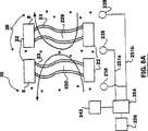
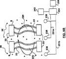
例示的に図8A及び8Bにおいて、垂直に向けられた中空繊維薄膜23を有する矩形かせ8で作った薄膜モジュール220は、図7Dに示すように薄膜モジュール220に対して配置された導管曝気槽238を有する循環曝気システム237によって空気に曝される。図8A及び図8Bにおいて、図面をわかりやすくするため、中空繊維薄膜23のたるみの程度が非常に誇張されている。更に、各々の垂直矩形かせ8に2つの中空繊維薄膜23しか図示されていないが、前述したように矩形かせ8は、実際には多くの中空繊維薄膜23で構築されるであろう。
【0038】
定常状態の曝気においては、気泡36が垂直矩形かせ8を貫通するのを促進するのが困難である。気泡236は、自然に薄膜モジュール220の周りや薄膜モジュール220の間のスロットを通るなど抵抗の最も少ない部分を通過する傾向があり、垂直矩形かせ8の外縁部上の中空繊維薄膜23は、気泡36と相当に多く接触する可能性がある。更に、中空繊維薄膜23の上部10から20%は、エアリフト効果によりきつく曲った形状に変形されることが多く、ほんの僅かしか動かない。中空繊維薄膜23の底部のより小さな部分はまた、下部ヘッダ22周りの水流により、きつい曲面となり得る。これらのきつい曲面部分において、中空繊維薄膜23は、比較的速く汚れる。
【0039】
しかし、循環曝気を用いると、より高い流量の空気がヘッダ251aとヘッダ251bとの間で交替される。より多くの空気がヘッダ251aに供給されると、中空繊維薄膜23は、図示のように第1の局所的再循環パターン280を伴って、図8Aに示す平均的な形状となる。ヘッダ251bに更に多くの空気が供給されると、中空繊維薄膜23は、図示のような第2の局所的再循環パターン282を伴う、図8Bに示す平均的な形状となる。循環曝気システム237の影響の下で、中空繊維薄膜23は、図8A及び図8Bに示す位置の間で交替する。従って、ほんの僅かしか動かない中空繊維薄膜23の部分はサイズが小さくなる。その周期はまた、垂直矩形かせ8の中へ及び垂直矩形かせ8からの逆流を生成し、本発明者は、それが気泡36の垂直矩形かせ8内への深い浸透を促進すると考えている。
【0040】
導管曝気槽
ここで、図9Aを参照すると、導管曝気槽238が示されている。導管曝気槽238は、内径が15ミリメートルと100ミリメートルとの間の円形パイプである細長い中空体302を有する。一連の孔304が中空体302を貫通し、空気を導管曝気槽238から外に流して気泡を生成する。孔の大きさ、数、及び、位置は、変動し得るが、例えば、矩形かせ8用には、直径が5ミリメートルと10ミリメートルとの間の2つの(各側面に1つ)孔を中空体302に沿って50ミリメートルから100ミリメートル毎に配置し、曝気槽300の深さにおいて孔を通る水柱で10ミリメートルと100ミリメートルとの間の圧力損失をもたらす空気流を供給されるものが適している。
【0041】
空気は、注入口306から導管曝気槽238に入る。導管曝気槽238の反対の端部に排出口308がある。曝気槽300の深さにおける孔304に亘る最低及び最高予想水柱圧力降下の間の垂直距離だけ、排出口308の最も高い点が注入口308上の最も低い点の下に位置する。孔304に亘る曝気槽300の深さにおける最低予想水柱圧力降下は、少なくとも孔304の頂部と中空体302の内側底部との間の距離と同じぐらいが好適である。曝気槽300の空気と曝気槽300周辺の水との間の空気/水インタフェース309は、中空体302の内側底部の下に位置するであろうが、排出口308の最高点の上方であろう。このように、導管曝気槽238に入るタンク水18は、排出口308へ流れることになり、孔304近くには溜まらないであろう。
【0042】
ここで、図9Bを参照すると、比較的清潔なタンク水18用に好適な別の導管曝気槽238が示されている。本体302の断面は矩形であるが、底部が開放されている。導管曝気槽238は、別個の構成要素か、又は、薄膜モジュール20のヘッダ22と一体になっていてもよく、その場合、下部ヘッダ22の底部が本体302の頂部の役目をし得る。本体302の端部は、これもヘッダ22の部分であり得るキャップ310によって蓋をされる。タンク水18に対して開放している本体302の底部により、導管曝気槽238内に浸透するタンク水18がタンク水18に流れて戻る。気泡36が導管曝気槽238の底部に発生するのを防ぐために、本体302の側面は、孔304を通る予想圧力降下を超える距離だけ孔304の底部の下に延びる。
【0043】
ここで、図9Cを参照すると、示されている別の導管曝気槽238は、本節で説明する以外は図9Aの導管曝気槽238とほぼ同じである。部分切取内部図で示されるゴムスリーブ400は、本体302を被覆し、孔304に対応するスリット402を有する。スリット402は、導管曝気槽238内に空気が流されると開き、高い流量の空気流が使用されるとより大きなサイズに開く。従って、スリット402により空気の流れが最大流量でより大きな気泡が発生し、空気の流量が小さくなるとより小さな気泡が発生する。廃水用途において、気泡36のサイズが小さくなると、小さな空気流量において酸素搬送効率の改善をもたらす。
【0044】
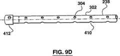
ここで、図9Dを参照すると、比較的固形物の多いタンク水18用に適した別の導管曝気槽が示されている。本体302は、直径32ミリメートルのチューブである。孔304は、直径が8ミリメートルであり、水平面から30度上向きに装着される。本体302の底部にある排水孔410は、一般に直径が16ミリメートルで、タンク水18を浸透させて本体302から排水する。キャップ412は、本体302の端部を覆う。
前述したような導管曝気槽238は、空気がそれを通って流れていてもいくらかのタンク水18を受け入れる可能性があり、それが乾燥して固形物の蓄積を残す。しかし、空気の供給が、前述したようにマニホルドの間で切り替えられる時、導管曝気槽238は、交替してあふれたり空になったりする。得られる導管曝気槽238の周期的な湿潤は、再湿潤するのを助け、導管曝気槽238に堆積している固形物を除去するのに役立ち、又は、タンク水18が乾いて導管曝気槽238に固形物が堆積するのを防ぐ。必要であれば、大気に通じるバルブを開放することにより適切なマニホルドから空気を放出し、この水の氾濫を促進できる。 本発明が開示する範囲内で、上記と類似の実施形態は、多くの代替形態として作ることができ、多くの代替方法に従って作動させることができる。
【0045】
実施例
次に示す実施例は、ゼノン・エンバイロンメンタル・インコーポレーテッドが製造する薄膜モジュールZW 500に関する。各々のZW 500は、2つの垂直中空繊維薄膜の矩形かせを有する。見かけ速度を計算する目的のため、各ZW 500薄膜モジュールの曝気の断面積は、約0.175平方メートルである。以下に与えられる空気流量は、全て標準条件での値である。
【0046】
実施例1
8つのZW 500薄膜モジュールをほぼ一定の処理パラメータで、フラックスと曝気とを変え、ベントナイトサスペンションにおいて運転した。薄膜の付着率を監視し、曝気の効果を評価した。曝気は、カセットに、204立方メートル/時間(すなわち、各モジュール当たり25.5立方メートル/時間)と136立方メートル/時間との一定流量で、様々な循環形態に従って供給された。循環試験において、総量136立方メートル/時間の空気供給が、モジュールの下方に置かれた曝気槽と、モジュールの間及び側面に置かれた曝気槽との間で、図10Aに示す時間間隔の周期で循環された。136立方メートル/時間で約30秒周期の循環曝気(曝気槽の各組に15秒の空気)は、204立方メートル/時間の非循環曝気とほぼ同じ効果があった。
【0047】
実施例2
ほぼ一定のパラメータで、図10Bに示すように空気流を変化させ、実施例1に述べたのと同じ装置を試験した。特に各々の組の曝気槽が総空気量の70%を10秒間、及び、総空気量の30%を10秒間受け取るように、総空気流量136立方メートル/時間の70%が20秒間周期で循環された。図10Bに示すように、空気流量の70%の循環により、同一の全空気流量における一定の曝気に比べ、高浸透フラックスにおいて、付着率が減少した。
【0048】
実施例3
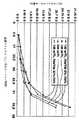
2つのZW 500薄膜モジュールを運転し、天然供給水から飲料水を製造した。運転パラメータは一定に保ったが、曝気を変化させた。モジュールは、最初の約10日間、モジュール当たり25.5立方メートル/時間(全システム空気流量51立方メートル/時間)の非循環曝気で運転した。次の3日間、空気が1組のモジュール近くの曝気槽から別のモジュール近くの曝気槽に切り替えられ、各々のモジュールが12.8立方メートル/時間で10秒間曝気され、次に、10秒間曝気されないようにした(総システム空気流量12.8立方メートル/時間)。次の10日間、モジュールが曝気され、各々のモジュールが25.5立方メートル/時間で10秒間曝気され、次に、10秒間曝気されないようにした(総システム空気流量25.5立方メートル/時間)。次の10日間、最初の一定空気流量に戻された。図10Cに示すように、各々のモジュールが25.5立方メートル/時間で10秒間曝気され、次に10秒間されなかったことで(すなわち、最初の総システム空気流量の1/2)、薄膜の浸透率が250L/平方メートル/時間/バールを超えたところで安定したのに対し、最初の総システム空気流量の非周期空気流量において薄膜の浸透率は、僅か、約125L/平方メートル/時間/バールのところで安定した。
【0049】
実施例4
各々が2つのZW 500薄膜モジュールを有する3台のユニットを薄膜バイオリアクタにおいてフラックスを種々変えて運転した。ユニット1は、26L/平方メートル/時間と51L/平方メートル/時間とで運転するモジュールを備えていた。ユニット2は、31L/平方メートル/時間と46L/平方メートル/時間とで運転するモジュールを備えていた。ユニット3は、34L/平方メートル/時間と51L/平方メートル/時間とで運転するモジュールを備えていた。それらのユニットは、最初約10日間、モジュール当たり42.5立方メートル/時間の非循環曝気(総システム空気流量85立方メートル/時間)で運転した。浸透率は、ユニット1において、250と275L/平方メートル/時間/バールとの間で、ユニット2において、200と225L/平方メートル/時間/バールとの間で、ユニット3において、150と175L/平方メートル/時間/バールとの間で減少して安定した。次の14日間、61.2立方メートル/時間の総システム空気流量がモジュール下部の曝気槽に10秒間加えられ、モジュール側面の曝気槽に10秒間加えられた。これらの条件下で、浸透率は、ユニット1において、350と375L/平方メートル/時間/バールとの間で、ユニット2及び3において、325と350L/平方メートル/時間/バールとの間で増加して安定した。
【0050】
実施例5
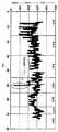
6つのZW 500モジュールのカセットを下水処理に使用した。他の処理パラメータを一定に保ち、曝気を変化させてモジュールの浸透率を図11に示すように周期的に計測した。期間Aで、255立方メートル/時間の空気を連続して均一に供給した。期間Bで、184立方メートル/時間の空気をモジュール下部の曝気槽に10秒間、次に、モジュール側面の曝気槽に10秒間加えた。期間Cで、同じ形態の曝気を適用したが、モジュールの周囲の囲いを変えた。期間Dで、184立方メートル/時間の空気をモジュールの第1の組に近い曝気槽に10秒間、次にモジュールの第2の組に近い曝気槽に10秒間加えた。期間Eで、204立方メートル/時間の空気を全てのモジュールに均一に10秒間加え、次にモジュールに10秒間空気を加えなかった。期間Fで、306立方メートル/時間の空気を全てのモジュールに均一に10秒間加え、次にモジュールに10秒間空気を加えなかった。期間Gで、153立方メートル/時間の空気をモジュールの第1の組に近い曝気槽に10秒間、次にモジュールの第2の組に近い曝気槽に10秒間加えた。
【0051】
実施例6
単一のZW 500薄膜モジュールを使って表面供給水を濾過した。他の処理パラメータを一定に保ち、曝気形態を種々変化させてモジュールを運転して浸透率を周期的に記録した。最初にモジュールを(a)20.4立方メートル/時間と、(b)25.5立方メートル/時間との一定の曝気で運転した。初期の透過率の減少後、透過率は、(a)約200L/平方メートル/時間/バールと、(b)275及び300L/平方メートル/時間/バールの間とで各々安定した。最初の実験において、モジュールに25.5立方メートル/時間で2分間曝気を加え、次に2分間止めた。この実験において、浸透率は急激に減少し、許容できるレベルに持続できなかった。しかし、別の実験において、モジュールに25.5立方メートル/時間で30秒間曝気を供給し、次に8.5立方メートル/時間で30秒間を供給した。この実験において、当初やはり浸透率が減少したが、後に275と300L/平方メートル/時間/バールとの間で安定した。
【図面の簡単な説明】
【図1A】 浸漬型薄膜リアクタの概略図である。
【図1B】 本発明の実施形態による薄膜モジュールを示す図である。
【図1C】 本発明の実施形態による薄膜モジュールを示す図である。
【図1D】 本発明の実施形態による薄膜モジュールを示す図である。
【図2】 本発明の実施形態による曝気システムの概略平面図である。
【図3】 本発明の実施形態の作動効果を示す一連のグラフである。
【図4A】 本発明の実施形態によるバルブセット及びバルブ制御装置の概略図である。
【図4B】 本発明の実施形態によるバルブセット及びバルブ制御装置の概略図である。
【図4C】 本発明の実施形態によるバルブセット及びバルブ制御装置の概略図である。
【図5】 本発明の実施形態による薄膜モジュール及び曝気システムの概略平面図である。
【図6】 本発明の別の実施形態による薄膜モジュール及び曝気システムの概略平面図である。
【図7A】 本発明の別の実施形態による薄膜モジュール及び曝気システムの概略平面図である。
【図7B】 図7Aに示す実施形態の代替形態による薄膜モジュール及び一部の曝気システムの立面図である。
【図7C】 図7Aに示す実施形態の代替形態による薄膜モジュール及び一部の曝気システムの立面図である。
【図7D】 図7Aに示す実施形態の代替形態による薄膜モジュール及び一部の曝気システムの立面図である。
【図8A】 循環曝気システムの影響の下にある本発明の実施形態による薄膜モジュール及び一部の曝気システムの立面図である。
【図8B】 循環曝気システムの影響の下にある本発明の実施形態による薄膜モジュール及び一部の曝気システムの立面図である。
【図9A】 本発明の実施形態による曝気槽を示す図である。
【図9B】 本発明の実施形態による曝気槽を示す図である。
【図9C】 本発明の実施形態による曝気槽を示す図である。
【図9D】 本発明の実施形態による曝気槽を示す図である。
【図10A】 2つのグループの曝気槽を有する本発明の実施形態で行われた試験結果を示すチャートである。
【図10B】 2つのグループの曝気槽を有する本発明の実施形態で行われた試験結果を示すチャートである。
【図10C】 2つのグループの曝気槽を有する本発明の実施形態で行われた試験結果を示すチャートである。
【図11】 1つのグループの曝気槽を有する本発明の実施形態で行われた試験結果を示すチャートである。[0001]
(Technical field)
The present invention relates to liquid filtration, and more particularly to cleaning or preventing thin film contamination of a submerged thin film filter using cleaning bubbles generated by an aeration tank.
[0002]
(Background technology)
Immersion membranes are used in the treatment of liquids, including solids, to produce a dilute solid filtrate and solids-rich unfiltered concentrate. For example, submerged thin films are used to extract substantially clean water from wastewater or to extract drinking water from lake water or reservoir water.
The membrane is typically placed in a module that includes a membrane and a header attached to the membrane. The module is immersed in a tank containing water containing solids. Intermembrane pressure is applied across the membrane walls, allowing filtered water to pass through the membrane walls. Solids are rejected by the thin film and remain in the tank water for microbiological or chemical treatment or discharged from the tank.
[0003]
The bubbles are sent into the tank through an aeration tank which is arranged below the thin film module and connected to the blower by a conduit. The bubbles rise to the surface of the tank water, creating an air lift that recirculates the tank water around the membrane module. When the air flow rate is within the effective range, the rising bubbles and the tank water wash out and agitate the thin film to suppress the solid matter in the tank from adhering to the pores of the thin film. Furthermore, oxygen is transferred from the bubbles to the tank water, and in the case of wastewater treatment, oxygen is supplied for the growth of microorganisms. The blower is generally operated continuously in order to minimize the stress on the blower motor and, if necessary, always supply the oxygen necessary for the growth of microorganisms.
[0004]
If further cleaning is required in a typical aeration system, the operator increases the air flow to the aeration tank. However, this method applies stress to the thin film and the blower motor and increases the energy consumption, so that the operation cost of the process is greatly increased. Conversely, if cleaning is relatively less, the operator typically reduces the air flow to the aeration tank. However, in this method, the air flow is always below the effective range and does not provide efficient cleaning. Alternatively, some operators may reduce the average air flow by supplying air intermittently. By this method, the air flow rate falls within the effective range, but instead wear is accelerated by frequent turning on and off of the blower. In many cases, such intermittent operation cancels the fan warranty.
[0005]
Another problem with typical aeration systems is that tank water is moved within the tank in a nearly steady-state recirculation pattern. The recirculation pattern generally includes a “dead zone” where recirculation tank water and bubbles do not reach the tank water. The thin films or parts thereof in these dead zones are not effectively washed and may be operated in water with a higher concentration of solids than normal tank water. Therefore, these thin films or the affected parts of these thin films are immediately soiled with solids.
A similar problem occurs in the module when the hollow fiber membrane is installed with some slack in order to move the membrane and shake off solids or avoid trapping solids. Tank water movement within the tank helps the sagging film to assume a nearly steady state position, particularly near the end of the film, which interferes with the beneficial movement of the fiber.
[0006]
Furthermore, another problem with current aeration systems is that the aeration tank itself often becomes fouled over time. Even while air is being supplied, the local air pressure near the periphery of the aeration tank holes is low, allowing tank water to penetrate into the aeration tank. For example, more tank water can enter the aeration system when aeration is occasionally stopped due to backwashing, cleaning or maintenance procedures. Some of the tank water that enters the aeration system then evaporates, leaving a solid precipitate in the aeration system. Especially in wastewater applications, the precipitated solids can significantly reduce the efficiency of the aeration system, or the operator can periodically interrupt the filtering action to clean or replace the aeration tank.
[0007]
(Disclosure of the Invention)
It is an object of the present invention to provide a circulating aeration system that can be used to aerate ultrafiltration and microfiltration membrane modules that are immersed in tank water of a tank. The circulating aeration system uses a valve set and a valve set controller to discharge the air supply device and connect it to a plurality of individual branches of the network. The individual branches of the air discharge network are then connected to an aeration tank located below the membrane module. While the air supply is operated to provide an initial steady air flow, the valve set and valve controller divides the initial air flow and distributes it to separate branches of the air distribution system, thereby The air flow to each individual branch alternates between a high flow rate and a low flow rate in a repeating cycle.
[0008]
In one embodiment, the circulating aeration system is used to prepare intermittent aeration for thin film modules that are located in a plurality of filtration zones, each with an air discharge and associated with a separate branch of the network. The circulating aeration system is configured and operated to supply aeration to each filtration zone in turn for a predetermined time. In another embodiment, a circulating aeration system is used to provide powerful aeration to a group of thin film modules. In one such embodiment, the circulating aeration system is configured to supply air to the branch of the air discharge network alternating between a high flow rate and a low flow rate with a period of 120 seconds or less. Drive. In another such embodiment, the aeration tank associated with the first branch of the air discharge network is interspersed between the aeration tanks associated with the second branch of the air discharge network. A high flow rate of air flow alternates between the first and second branches of the air discharge network with a period of 120 seconds or less.
The best embodiment of the present invention will now be described with reference to the accompanying drawings.
[0009]
(Best Mode for Carrying Out the Invention)
General description
Referring to FIG. 1, the general arrangement of the
The
[0010]
One or
By changing the form of the header, the
[0011]
1B, 1C and 1D show a preferred
Although a single row of
[0012]
Referring again to FIG. 1A, during infiltration, the
[0013]
During infiltration, the
The
[0014]
The
[0015]
The
[0016]
The average diameter of the
[0017]
[0018]
Circulating aeration tank
Referring now to FIG. 2, a circulating
[0019]
The
The valve set 254 and the
[0020]
An example is shown in FIG. In each part a), b) and c) of FIG. 3, Rh indicates a high flow rate, Rl indicates a low flow rate, and the time from 0 to t3 indicates the period that will be repeated. The period is divided into three substantially equal time intervals, 0 to t1, t1 to t2, and t2 to t3. In each of these time intervals, one branch of the
[0021]
Many of the valve sets 254 described below can be used to create smooth fluctuations in the air flow to the manifold 251, but it is preferred that the changes be fairly rapid as shown in FIG. The inventor has noted that such a rapid change produces a short burst of unusually
[0022]
The amount of air supplied to the manifold 251 or branch of the
Rl is usually less than half of Rh and is often in an air-off state with no flow. Within this range, the low air flow rate is affected by the quality of the feed water 14. Although an air-off condition is usually preferred, the supply of some amount of feed water 14 causes the
[0023]
Referring to FIGS. 4A, 4B, and 4C, an alternate embodiment of valve set 254 and
[0024]
In FIG. 4B, the
In FIG. 4C, the
[0025]
Use of circulating aeration for efficient intermittent aeration
Although the use of a circulating
[0026]
The
[0027]
It is preferable that the back washing of the
[0028]
For example, in a preliminary study conducted with feed water with turbidity of 0.3 ntu and chromaticity of 3.9 tcu, the inventor has shown that 75 seconds every 15
[0029]
Use of circulating aeration for strong aeration
Here, the use of a circulating
[0030]
The
[0031]
The preferred total period may vary depending on the depth of the
[0032]
The inventor believes that a transient flow occurs in the
[0033]
Use of circulating aeration to promote horizontal flow
Although the use of circulating aeration to promote horizontal flow of
The
[0034]
The
[0035]
The total period may vary depending on the depth of the
[0036]
In this embodiment having
[0037]
Illustratively in FIGS. 8A and 8B, a
[0038]
In steady state aeration, it is difficult to facilitate the
[0039]
However, when circulating aeration is used, higher flow rate air is alternated between
[0040]
Pipe aeration tank
Referring now to FIG. 9A, a
[0041]
Air enters the
[0042]
Referring now to FIG. 9B, there is shown another
[0043]
Referring now to FIG. 9C, the other
[0044]
Referring now to FIG. 9D, another conduit aeration tank suitable for relatively
The
[0045]
Example
The following embodiment relates to a thin
[0046]
Example 1
Eight ZW 500 thin film modules were operated in bentonite suspension with nearly constant processing parameters, varying flux and aeration. The adhesion rate of the thin film was monitored to evaluate the effect of aeration. Aeration was supplied to the cassette at a constant flow rate of 204 cubic meters / hour (ie, 25.5 cubic meters / hour for each module) and 136 cubic meters / hour according to various circulation configurations. In the circulation test, a total air supply of 136 cubic meters / hour is supplied between the aeration tank placed below the module and the aeration tank placed between the modules and on the side surface at the period of the time interval shown in FIG. 10A. It was circulated. Circulating aeration with a period of about 30 seconds at 136 cubic meters / hour (15 seconds of air in each set of aeration tanks) had almost the same effect as a non-circulating aeration of 204 cubic meters / hour.
[0047]
Example 2
With the almost constant parameters, the same apparatus as described in Example 1 was tested, varying the air flow as shown in FIG. 10B. Specifically, 70% of the total air flow of 136 cubic meters / hour is circulated in a cycle of 20 seconds so that each set of aeration tanks receives 70% of the total air volume for 10 seconds and 30% of the total air volume for 10 seconds. It was. As shown in FIG. 10B, the adhesion rate decreased in the high osmotic flux compared to constant aeration at the same total air flow rate due to the circulation of 70% of the air flow rate.
[0048]
Example 3
Two ZW 500 thin film modules were operated to produce drinking water from natural feed water. The operating parameters were kept constant, but the aeration was changed. The module was operated with a non-circulating aeration of 25.5 cubic meters / hour per module (total system air flow of 51 cubic meters / hour) for the first approximately 10 days. During the next 3 days, air is switched from one aeration tank near one set of modules to an aeration tank near another module, and each module is aerated at 12.8 cubic meters / hour for 10 seconds and then not aerated for 10 seconds (Total system air flow 12.8 cubic meters / hour). During the next 10 days, the modules were aerated and each module was aerated for 10 seconds at 25.5 cubic meters / hour and then not aerated for 10 seconds (total system air flow 25.5 cubic meters / hour). The first constant air flow was restored for the next 10 days. As shown in FIG. 10C, each module was aerated for 10 seconds at 25.5 cubic meters / hour and then not for 10 seconds (
[0049]
Example 4
Three units, each with two ZW 500 thin film modules, were operated in the thin film bioreactor with varying flux.
[0050]
Example 5
Six ZW 500 module cassettes were used for sewage treatment. The other process parameters were kept constant, the aeration was changed, and the module penetration rate was measured periodically as shown in FIG. In period A, air of 255 cubic meters / hour was continuously supplied uniformly. In period B, 184 cubic meters / hour of air was added to the aeration tank at the bottom of the module for 10 seconds and then to the aeration tank on the side of the module for 10 seconds. In period C, the same form of aeration was applied, but the enclosure around the module was changed. In period D, 184 cubic meters / hour of air was added to the aeration tank near the first set of modules for 10 seconds and then to the aeration tank near the second set of modules for 10 seconds. In period E, 204 cubic meters / hour of air was uniformly applied to all modules for 10 seconds, and then no air was applied to the modules for 10 seconds. In period F, 306 cubic meters / hour of air was uniformly applied to all modules for 10 seconds, and then no air was applied to the modules for 10 seconds. In period G, 153 cubic meters / hour of air was added to the aeration tank near the first set of modules for 10 seconds and then to the aeration tank near the second set of modules for 10 seconds.
[0051]
Example 6
The surface feed water was filtered using a
[Brief description of the drawings]
FIG. 1A is a schematic view of an immersion type thin film reactor.
FIG. 1B shows a thin film module according to an embodiment of the present invention.
FIG. 1C shows a thin film module according to an embodiment of the present invention.
FIG. 1D shows a thin film module according to an embodiment of the present invention.
FIG. 2 is a schematic plan view of an aeration system according to an embodiment of the present invention.
FIG. 3 is a series of graphs showing operational effects of an embodiment of the present invention.
FIG. 4A is a schematic diagram of a valve set and a valve control device according to an embodiment of the present invention.
FIG. 4B is a schematic view of a valve set and a valve control device according to an embodiment of the present invention.
FIG. 4C is a schematic view of a valve set and a valve control device according to an embodiment of the present invention.
FIG. 5 is a schematic plan view of a thin film module and an aeration system according to an embodiment of the present invention.
FIG. 6 is a schematic plan view of a thin film module and an aeration system according to another embodiment of the present invention.
FIG. 7A is a schematic plan view of a thin film module and an aeration system according to another embodiment of the present invention.
7B is an elevational view of a thin film module and some aeration systems according to an alternative to the embodiment shown in FIG. 7A.
7C is an elevational view of a thin film module and some aeration systems according to an alternative to the embodiment shown in FIG. 7A.
7D is an elevation view of a thin film module and some aeration systems according to an alternative to the embodiment shown in FIG. 7A.
FIG. 8A is an elevation view of a thin film module and some aeration systems according to an embodiment of the invention under the influence of a circulating aeration system.
FIG. 8B is an elevational view of a thin film module and some aeration systems according to an embodiment of the invention under the influence of a circulating aeration system.
FIG. 9A is a diagram showing an aeration tank according to an embodiment of the present invention.
FIG. 9B is a diagram showing an aeration tank according to an embodiment of the present invention.
FIG. 9C is a diagram showing an aeration tank according to an embodiment of the present invention.
FIG. 9D is a diagram showing an aeration tank according to an embodiment of the present invention.
FIG. 10A is a chart showing the results of tests performed in an embodiment of the present invention having two groups of aeration tanks.
FIG. 10B is a chart showing the results of tests performed in an embodiment of the present invention having two groups of aeration tanks.
FIG. 10C is a chart showing the results of tests performed in an embodiment of the present invention having two groups of aeration tanks.
FIG. 11 is a chart showing the results of tests performed in an embodiment of the present invention having one group of aeration tanks.
Claims (22)
Translated fromJapanese(a)複数の個別のブランチを有するガス吐出しネットワークと、
(b)前記ガス吐出しネットワークの前記個別のブランチに流体連結され、前記薄膜モジュールの下方に装着可能な1つ又はそれ以上のエアレータと、
(c)概ね一定のガス流の流量を供給するガス供給装置と、
(d)前記ガス供給装置と流体連結され、前記ガス吐出しネットワークの前記個別のブランチと流体連結された個別の排出口を有するバルブセットの1つ又はそれ以上のバルブを備えた
曝気装置において、
(e)前記バルブセットの1つ又はそれ以上のバルブが、バルブセット制御装置に機械的にか、電気的にリンクされており、該バルブセット制御装置が、前記バルブを自動的に制御して、(i)前記ガス吐出しネットワークの少なくとも1つの個別のブランチが比較的高流量のガスを受け、前記ガス吐出しネットワークの少なくとも1つの他の個別のブランチが、前記比較的高流量の2分の1以下の比較的低流量のガスを受けるように、前記ガス流を分割し、かつ(ii)継続時間120秒以下の繰り返し周期で、前記ガス吐出しネットワークの前記少なくとも1つの個別のブランチと前記少なくとも1つの他の個別のブランチが受けるガスを前記比較的高流量と比較的低流量の間で切り換えるようにしたことを特徴とする曝気装置。An aeration device for aeration of tank water in a tank containing one or more submerged membrane modules,
(A) a gas delivery network having a plurality of individual branches;
(B) one or more aerators fluidly connected to the individual branches of the gas delivery network and attachable below the thin film module;
(C) a gas supply device for supplying a flow rate of a substantially constant gas flow;
(D) an aeration apparatus comprising one or more valves of a valve set fluidly connected to the gas supply device and having individual outlets fluidly connected to the individual branches of the gas discharge network;
(E) one or more valves of the valve set are mechanically or electrically linked to a valve set controller, the valve set controller automatically controlling the valve; (I) at least one individual branch of the gas delivery network receives a relatively high flow of gas, and at least one other individual branch of the gas delivery network receives the relatively high flow of 2 minutes; Dividing the gas stream to receive a relatively low flow gas of 1 or less, and (ii) at least one individual branch of the gas delivery network with a repetition period of 120 seconds or less in duration. An aeration apparatus characterized in that the gas received by the at least one other individual branch is switched between the relatively high flow rate and the relatively low flow rate.
Applications Claiming Priority (11)
| Application Number | Priority Date | Filing Date | Title |
|---|---|---|---|
| US10366598P | 1998-10-09 | 1998-10-09 | |
| CA2258715 | 1999-01-14 | ||
| CA2,258,715 | 1999-01-14 | ||
| US11659199P | 1999-01-20 | 1999-01-20 | |
| CA 2278085CA2278085A1 (en) | 1999-07-20 | 1999-07-20 | Aeration system for submerged membrane module |
| CA2,278,085 | 1999-07-20 | ||
| CA60/116,591 | 1999-07-30 | ||
| CA2,279,766 | 1999-07-30 | ||
| CA60/103,665 | 1999-07-30 | ||
| CA 2279766CA2279766A1 (en) | 1999-07-30 | 1999-07-30 | Aeration system for submerged membrane module |
| PCT/CA1999/000940WO2000021890A1 (en) | 1998-10-09 | 1999-10-07 | Cyclic aeration system for submerged membrane modules |
Publications (2)
| Publication Number | Publication Date |
|---|---|
| JP2002527229A JP2002527229A (en) | 2002-08-27 |
| JP3645814B2true JP3645814B2 (en) | 2005-05-11 |
Family
ID=27508676
Family Applications (1)
| Application Number | Title | Priority Date | Filing Date |
|---|---|---|---|
| JP2000575802AExpired - LifetimeJP3645814B2 (en) | 1998-10-09 | 1999-10-07 | Circulating aeration system for submerged thin film modules |
Country Status (14)
| Country | Link |
|---|---|
| US (1) | US6245239B1 (en) |
| EP (4) | EP2204353A3 (en) |
| JP (1) | JP3645814B2 (en) |
| KR (1) | KR100439436B1 (en) |
| AT (1) | ATE264272T1 (en) |
| AU (1) | AU765966C (en) |
| BR (1) | BR9914376A (en) |
| CA (1) | CA2345682C (en) |
| CZ (1) | CZ300382B6 (en) |
| DE (1) | DE69916479T2 (en) |
| ES (1) | ES2220113T3 (en) |
| HU (1) | HU224463B1 (en) |
| PL (1) | PL214717B1 (en) |
| WO (1) | WO2000021890A1 (en) |
Cited By (2)
| Publication number | Priority date | Publication date | Assignee | Title |
|---|---|---|---|---|
| WO2013002242A1 (en)* | 2011-06-29 | 2013-01-03 | 東レ株式会社 | Film separation activated sludge method film surface cleaning method |
| WO2013146920A1 (en) | 2012-03-30 | 2013-10-03 | 東レ株式会社 | Method for producing chemical by means of continuous fermentation and continuous fermentation device |
Families Citing this family (142)
| Publication number | Priority date | Publication date | Assignee | Title |
|---|---|---|---|---|
| US7037426B2 (en) | 2000-05-04 | 2006-05-02 | Zenon Environmental Inc. | Immersed membrane apparatus |
| US6863823B2 (en)* | 2001-03-23 | 2005-03-08 | Zenon Environmental Inc. | Inverted air box aerator and aeration method for immersed membrane |
| US20020134740A1 (en)* | 2001-03-23 | 2002-09-26 | Pierre Cote | Inverted air box aerator and aeration method for immersed membrane |
| DE69632422T2 (en)* | 1995-08-11 | 2005-05-19 | Zenon Environmental Inc., Oakville | Process for embedding hollow fiber membranes |
| US8852438B2 (en) | 1995-08-11 | 2014-10-07 | Zenon Technology Partnership | Membrane filtration module with adjustable header spacing |
| US7087173B2 (en) | 1995-08-11 | 2006-08-08 | Zenon Environmental Inc. | Inverted cavity aerator for membrane module |
| US6656356B2 (en) | 1998-10-09 | 2003-12-02 | Zenon Environmental Inc. | Aerated immersed membrane system |
| US20040232076A1 (en)* | 1996-12-20 | 2004-11-25 | Fufang Zha | Scouring method |
| ES2353254T3 (en) | 1996-12-20 | 2011-02-28 | Siemens Water Technologies Corp. | WASHING PROCEDURE |
| US6641733B2 (en)* | 1998-09-25 | 2003-11-04 | U. S. Filter Wastewater Group, Inc. | Apparatus and method for cleaning membrane filtration modules |
| US7014173B2 (en)* | 1998-10-09 | 2006-03-21 | Zenon Environmental Inc. | Cyclic aeration system for submerged membrane modules |
| US6550747B2 (en) | 1998-10-09 | 2003-04-22 | Zenon Environmental Inc. | Cyclic aeration system for submerged membrane modules |
| EP2204353A3 (en)* | 1998-10-09 | 2010-09-15 | Zenon Technology Partnership | Cyclic aeration system for submerged membrane modules |
| US6706189B2 (en)* | 1998-10-09 | 2004-03-16 | Zenon Environmental Inc. | Cyclic aeration system for submerged membrane modules |
| ATE292511T1 (en)* | 1998-11-23 | 2005-04-15 | Zenon Environmental Inc | WATER FILTRATION USING UNDERWATER MEMBRANES |
| US20040007527A1 (en)* | 1998-11-23 | 2004-01-15 | Zenon Environmental Inc. | Membrane filtration device and process |
| CA2290053C (en)* | 1999-11-18 | 2009-10-20 | Zenon Environmental Inc. | Immersed membrane module and process |
| US6616843B1 (en)* | 1998-12-18 | 2003-09-09 | Omnium De Traitement Et De Valorisation | Submerged membrane bioreactor for treatment of nitrogen containing water |
| AUPP985099A0 (en)* | 1999-04-20 | 1999-05-13 | Usf Filtration And Separations Group Inc. | Membrane filtration manifold system |
| US20010052494A1 (en)* | 1999-10-25 | 2001-12-20 | Pierre Cote | Chemical cleaning backwash for normally immersed membranes |
| KR20010092783A (en)* | 1999-11-18 | 2001-10-26 | 추후보정 | Immersed membrane filtration system and overflow process |
| AUPQ680100A0 (en)* | 2000-04-10 | 2000-05-11 | Usf Filtration And Separations Group Inc. | Hollow fibre restraining system |
| AUPR143400A0 (en) | 2000-11-13 | 2000-12-07 | Usf Filtration And Separations Group Inc. | Modified membranes |
| DE10106722B4 (en)* | 2001-02-14 | 2008-11-06 | Fraunhofer-Gesellschaft zur Förderung der angewandten Forschung e.V. | Special hollow fiber membrane module for use in heavily fouled processes and its production |
| ATE288607T1 (en)* | 2001-03-12 | 2005-02-15 | Magellan Dis Inc | OFF-BOARD NAVIGATION SYSTEM WITH PERSONALIZED NAVIGATION DATABASE |
| US20020170863A1 (en)* | 2001-03-16 | 2002-11-21 | Manwinder Singh | Carbon dioxide recycle for immersed membrane |
| AUPR421501A0 (en) | 2001-04-04 | 2001-05-03 | U.S. Filter Wastewater Group, Inc. | Potting method |
| AUPR584301A0 (en) | 2001-06-20 | 2001-07-12 | U.S. Filter Wastewater Group, Inc. | Membrane polymer compositions |
| AUPR692401A0 (en) | 2001-08-09 | 2001-08-30 | U.S. Filter Wastewater Group, Inc. | Method of cleaning membrane modules |
| AUPR774201A0 (en)* | 2001-09-18 | 2001-10-11 | U.S. Filter Wastewater Group, Inc. | High solids module |
| EP1312408B1 (en)* | 2001-11-16 | 2006-07-19 | US Filter Wastewater Group, Inc. | Method of cleaning membranes |
| JP2003172291A (en)* | 2001-12-04 | 2003-06-20 | Boc Edwards Technologies Ltd | Vacuum pump |
| WO2003059495A1 (en) | 2002-01-09 | 2003-07-24 | Hydranautics | Methods for improving filtration performance of hollow fiber membranes |
| US7247238B2 (en) | 2002-02-12 | 2007-07-24 | Siemens Water Technologies Corp. | Poly(ethylene chlorotrifluoroethylene) membranes |
| NL1020374C2 (en)* | 2002-04-12 | 2003-10-14 | Memfis B V | Device for cleaning a liquid medium. |
| AUPS300602A0 (en) | 2002-06-18 | 2002-07-11 | U.S. Filter Wastewater Group, Inc. | Methods of minimising the effect of integrity loss in hollow fibre membrane modules |
| AU2002950934A0 (en)* | 2002-08-21 | 2002-09-12 | U. S. Filter Wastewater Group, Inc. | Aeration method |
| KR101002466B1 (en) | 2002-10-10 | 2010-12-17 | 지멘스 워터 테크놀로지스 코포레이션 | Back wash method |
| US6863817B2 (en)* | 2002-12-05 | 2005-03-08 | Zenon Environmental Inc. | Membrane bioreactor, process and aerator |
| AU2002953111A0 (en) | 2002-12-05 | 2002-12-19 | U. S. Filter Wastewater Group, Inc. | Mixing chamber |
| AU2003297476A1 (en)* | 2002-12-19 | 2004-07-14 | Hydranautics | Methods for cleaning and maintaining membrane surface during filtration |
| DE602004013731D1 (en)* | 2003-03-05 | 2008-06-26 | Hydranautics | DIPLOCKABLE MEMBRANE MODULE WITH REPLACEABLE MEMBRANE ELEMENTS |
| US20040262209A1 (en)* | 2003-04-25 | 2004-12-30 | Hiroyuki Umezawa | Filtration apparatus |
| US6964738B1 (en)* | 2003-06-18 | 2005-11-15 | The United States Of America As Represented By The Secretary Of The Navy | Bioreactor processing of wastewater |
| AU2003903507A0 (en) | 2003-07-08 | 2003-07-24 | U. S. Filter Wastewater Group, Inc. | Membrane post-treatment |
| NZ545206A (en) | 2003-08-29 | 2009-03-31 | Siemens Water Tech Corp | Backwash |
| US7879229B2 (en)* | 2003-10-29 | 2011-02-01 | Zenon Technology Partnership | Water treatment plant with immersed membranes |
| US8114293B2 (en)* | 2003-10-29 | 2012-02-14 | Zenon Technology Partnership | Method of operating a water treatment plant with immersed membranes |
| CA2544626C (en) | 2003-11-14 | 2016-01-26 | U.S. Filter Wastewater Group, Inc. | Closed aeration and backwash device for use with membrane filtration module |
| US8758621B2 (en) | 2004-03-26 | 2014-06-24 | Evoqua Water Technologies Llc | Process and apparatus for purifying impure water using microfiltration or ultrafiltration in combination with reverse osmosis |
| JP2007535398A (en) | 2004-04-22 | 2007-12-06 | シーメンス ウォーター テクノロジース コーポレイション | Filtration device including membrane bioreactor and treatment tank for digesting organic substances, and waste liquid treatment method |
| FR2869552B1 (en)* | 2004-04-29 | 2007-04-06 | Otv Sa | FILTERING DEVICE FOR THE TREATMENT OF WATER, OF THE TYPE OF IMMERSIONED MEMBRANES, INCLUDING ANTI-FLOW MEANS OF THE MEDIUM TO BE FILTERED TO MEANS FOR INJECTING A DECOLMING GAS. |
| CN102512986A (en) | 2004-07-02 | 2012-06-27 | 西门子工业公司 | Gas transfer membrane |
| EP1773477B1 (en) | 2004-07-05 | 2011-09-07 | Siemens Water Technologies Corp. | Hydrophilic membranes |
| CN101052457B (en) | 2004-08-20 | 2012-07-04 | 西门子工业公司 | Square mbr manifold system |
| CN101043933B (en) | 2004-09-07 | 2012-09-05 | 西门子工业公司 | Reduction of backwash liquid waste |
| AU2005284677B2 (en) | 2004-09-14 | 2010-12-23 | Evoqua Water Technologies Llc | Methods and apparatus for removing solids from a membrane module |
| NZ553771A (en) | 2004-09-15 | 2010-11-26 | Siemens Water Tech Corp | Continuously variable aeration of membrane filtration system and flow control device when used in such application |
| US7118674B2 (en)* | 2004-10-14 | 2006-10-10 | Itt Manufacturing Enterprises, Inc. | Energy-efficient biological treatment with membrane filtration |
| US7591950B2 (en) | 2004-11-02 | 2009-09-22 | Siemens Water Technologies Corp. | Submerged cross-flow filtration |
| KR20070089981A (en) | 2004-12-03 | 2007-09-04 | 지멘스 워터 테크놀로지스 코포레이션 | Post-treatment of membrane |
| US20060118487A1 (en)* | 2004-12-07 | 2006-06-08 | Adams Nicholas W H | Membrane filtration process |
| WO2006066350A1 (en) | 2004-12-24 | 2006-06-29 | Siemens Water Technologies Corp. | Simple gas scouring method and apparatus |
| WO2006066319A1 (en) | 2004-12-24 | 2006-06-29 | Siemens Water Technologies Corp. | Cleaning in membrane filtration systems |
| JP2008539054A (en) | 2005-04-29 | 2008-11-13 | シーメンス・ウォーター・テクノロジーズ・コーポレイション | Chemical cleaning for membrane filters |
| EP2314368B1 (en)* | 2005-07-12 | 2016-09-14 | Zenon Technology Partnership | Process control for an immersed membrane system |
| CN101222972B (en) | 2005-07-14 | 2014-12-03 | 伊沃夸水处理技术有限责任公司 | Monopersulfate treatment of membranes |
| US8858796B2 (en) | 2005-08-22 | 2014-10-14 | Evoqua Water Technologies Llc | Assembly for water filtration using a tube manifold to minimise backwash |
| WO2007044345A2 (en) | 2005-10-05 | 2007-04-19 | Siemens Water Technologies Corp. | Method and apparatus for treating wastewater |
| US20070138090A1 (en) | 2005-10-05 | 2007-06-21 | Jordan Edward J | Method and apparatus for treating wastewater |
| US20070084795A1 (en)* | 2005-10-05 | 2007-04-19 | Jordan Edward J | Method and system for treating wastewater |
| US20070095754A1 (en)* | 2005-10-28 | 2007-05-03 | Dennis Livingston | Efficient MBR operation in wastewater treatment |
| KR20080085906A (en)* | 2006-01-12 | 2008-09-24 | 지멘스 워터 테크놀로지스 코포레이션 | Improved Operation Strategy in Filtration Processes |
| US7455765B2 (en) | 2006-01-25 | 2008-11-25 | Siemens Water Technologies Corp. | Wastewater treatment system and method |
| US8293098B2 (en) | 2006-10-24 | 2012-10-23 | Siemens Industry, Inc. | Infiltration/inflow control for membrane bioreactor |
| KR100834712B1 (en) | 2006-12-29 | 2008-06-02 | 주식회사 코오롱 | Cassette cleaning apparatus and method for cleaning cassettes using the same |
| KR100786201B1 (en)* | 2006-12-29 | 2007-12-17 | 주식회사 코오롱 | An apparatus for cleansing a cassette and a method for cleaning the cassette using the same |
| US8318028B2 (en) | 2007-04-02 | 2012-11-27 | Siemens Industry, Inc. | Infiltration/inflow control for membrane bioreactor |
| US9764288B2 (en) | 2007-04-04 | 2017-09-19 | Evoqua Water Technologies Llc | Membrane module protection |
| CA2686924A1 (en)* | 2007-05-10 | 2008-11-20 | Toray Industries, Inc. | Submerged membrane separation apparatus with improved diffuser tube structure |
| AU2010256746B2 (en)* | 2009-06-02 | 2012-09-27 | Evoqua Water Technologies Llc | Membrane cleaning with pulsed gas slugs and global aeration |
| CA2688455C (en) | 2007-05-29 | 2019-12-03 | Siemens Water Technologies Corp. | Pulsed random two phase gas/liquid flow for cleaning membrane surfaces |
| TW200927274A (en)* | 2007-09-18 | 2009-07-01 | Asahi Kasei Chemicals Corp | Hollow yarn film filtering apparatus |
| US20090071901A1 (en)* | 2007-09-19 | 2009-03-19 | Rabie Hamid R | System and method for filtering liquids |
| ES2337648B1 (en)* | 2007-12-04 | 2011-03-10 | Micronet Porous Fibers,S.L. | FILTER WASHING SYSTEM AND ITS PROCEDURE. |
| JP5362343B2 (en)* | 2008-01-11 | 2013-12-11 | 旭化成ケミカルズ株式会社 | Membrane separation unit |
| KR100834713B1 (en)* | 2008-02-26 | 2008-06-02 | 주식회사 코오롱 | Cassette cleaning apparatus and method for cleaning cassettes using the same |
| WO2010009518A1 (en) | 2008-07-24 | 2010-01-28 | Siemens Water Technologies Corp. | Frame system for membrane filtration modules |
| JP2012500117A (en) | 2008-08-20 | 2012-01-05 | シーメンス ウォーター テクノロジース コーポレイション | Improving backwash energy efficiency of membrane filtration systems. |
| AU2010205867A1 (en)* | 2009-01-14 | 2011-07-21 | Bl Technologies, Inc. | Immersed membrane cassette and method of operation |
| US20100258502A1 (en)* | 2009-02-06 | 2010-10-14 | Butters Brian E | Advanced Oxidation Enhancements and High Temperature treatment of Contaminated Media |
| EP2411127B1 (en) | 2009-03-26 | 2022-01-05 | BL Technologies, Inc. | Non-braided reinforced hollow fibre membrane |
| ES2363847B1 (en)* | 2009-04-17 | 2012-08-09 | Micronet-Porous Fibers, S.L. | FILTER WASHING SYSTEM. |
| AU2010101488B4 (en) | 2009-06-11 | 2013-05-02 | Evoqua Water Technologies Llc | Methods for cleaning a porous polymeric membrane and a kit for cleaning a porous polymeric membrane |
| ITPI20090078A1 (en)* | 2009-06-19 | 2010-12-19 | Zetaplast S P A | MODULAR TANK FOR WASTEWATER TREATMENT |
| US9061250B2 (en) | 2009-06-26 | 2015-06-23 | Bl Technologies, Inc. | Non-braided, textile-reinforced hollow fiber membrane |
| US9358505B2 (en) | 2009-09-03 | 2016-06-07 | General Electric Company | Gas sparger for an immersed membrane |
| US8505881B2 (en) | 2009-10-12 | 2013-08-13 | Enviromix, Llc | Mixing systems and methods of mixing |
| WO2011136888A1 (en) | 2010-04-30 | 2011-11-03 | Siemens Industry, Inc | Fluid flow distribution device |
| DE102010019505B4 (en) | 2010-05-06 | 2016-09-29 | Microdyn - Nadir Gmbh | Filtration device with internal recirculation |
| CN103097008B (en) | 2010-09-15 | 2015-12-09 | Bl科技公司 | The method of yarn enhanced hollow-fibre membrane is manufactured around solvable core body |
| WO2012040412A1 (en) | 2010-09-24 | 2012-03-29 | Siemens Industry, Inc. | Fluid control manifold for membrane filtration system |
| US8323498B2 (en) | 2010-10-04 | 2012-12-04 | Enviromix, Llc | Systems and methods for automated control of mixing and aeration in treatment processes |
| US9364805B2 (en) | 2010-10-15 | 2016-06-14 | General Electric Company | Integrated gas sparger for an immersed membrane |
| CN102451618A (en)* | 2010-10-28 | 2012-05-16 | 绵阳美能材料科技有限公司 | System and method for carrying out gas washing on immersed hollow fibrous membranes |
| US8529814B2 (en) | 2010-12-15 | 2013-09-10 | General Electric Company | Supported hollow fiber membrane |
| US9101857B2 (en) | 2011-04-26 | 2015-08-11 | Therapeutic Proteins International, LLC | Gas scrubbed perfusion filter |
| US8910799B2 (en) | 2011-08-01 | 2014-12-16 | Enveera, Inc. | Integrated membrane system for distributed water treatment |
| US8876089B2 (en) | 2011-09-15 | 2014-11-04 | Zenon Technology Partnership | Method and apparatus to keep an aerator full of air |
| WO2013048801A1 (en) | 2011-09-30 | 2013-04-04 | Siemens Industry, Inc. | Improved manifold arrangement |
| KR102177864B1 (en) | 2011-09-30 | 2020-11-13 | 에보쿠아 워터 테크놀로지스 엘엘씨 | Isolation valve |
| US9321014B2 (en) | 2011-12-16 | 2016-04-26 | Bl Technologies, Inc. | Hollow fiber membrane with compatible reinforcements |
| US9643129B2 (en) | 2011-12-22 | 2017-05-09 | Bl Technologies, Inc. | Non-braided, textile-reinforced hollow fiber membrane |
| KR101154825B1 (en)* | 2011-12-29 | 2012-06-18 | 코오롱환경서비스주식회사 | Air control actuator and submerged membrane module aeration system using the same |
| US9463419B2 (en) | 2012-01-09 | 2016-10-11 | General Electric Company | Pulse aeration for immersed membranes |
| US9022229B2 (en) | 2012-03-09 | 2015-05-05 | General Electric Company | Composite membrane with compatible support filaments |
| US8999454B2 (en) | 2012-03-22 | 2015-04-07 | General Electric Company | Device and process for producing a reinforced hollow fibre membrane |
| WO2014004645A1 (en) | 2012-06-28 | 2014-01-03 | Siemens Industry, Inc. | A potting method |
| US9227362B2 (en) | 2012-08-23 | 2016-01-05 | General Electric Company | Braid welding |
| JPWO2014034836A1 (en)* | 2012-08-30 | 2016-08-08 | 東レ株式会社 | Membrane separation cleaning method for activated sludge |
| DE112013004713T5 (en) | 2012-09-26 | 2015-07-23 | Evoqua Water Technologies Llc | Membrane safety device |
| AU2013231145B2 (en) | 2012-09-26 | 2017-08-17 | Evoqua Water Technologies Llc | Membrane potting methods |
| AU2013323934A1 (en) | 2012-09-27 | 2015-02-26 | Evoqua Water Technologies Llc | Gas scouring apparatus for immersed membranes |
| CN104768632B (en) | 2012-11-14 | 2016-11-09 | 通用电气公司 | Method for flushing a submerged membrane using a bottom-opening multi-channel delivery device |
| CN104780998B (en)* | 2012-11-14 | 2018-04-24 | 通用电气公司 | Bottom-open multi-channel gas conveying device for submerged membrane |
| EP3052221B1 (en) | 2013-10-02 | 2022-12-14 | Rohm & Haas Electronic Materials Singapore Pte. Ltd | Device for repairing a membrane filtration module |
| BR112017008397B1 (en) | 2014-10-22 | 2022-08-09 | Koch Separation Solutions, Inc | MEMBRANE FILTER MODULE CONFIGURED TO TREAT A LIQUID CONTAINED IN A TANK AT AMBIENT PRESSURE AND MEMBRANE FILTER |
| US10322375B2 (en) | 2015-07-14 | 2019-06-18 | Evoqua Water Technologies Llc | Aeration device for filtration system |
| USD779631S1 (en) | 2015-08-10 | 2017-02-21 | Koch Membrane Systems, Inc. | Gasification device |
| CN105948246A (en)* | 2015-09-01 | 2016-09-21 | 江西金达莱环保股份有限公司 | Non-zoned membrane biological sewage treatment method and non-zoned membrane biological sewage treatment system |
| WO2017196384A1 (en) | 2016-05-09 | 2017-11-16 | Global Algae Innovations, Inc. | Biological and algae harvesting and cultivation systems and methods |
| US11767501B2 (en) | 2016-05-09 | 2023-09-26 | Global Algae Technology, LLC | Biological and algae harvesting and cultivation systems and methods |
| JP2018167184A (en)* | 2017-03-30 | 2018-11-01 | 三菱ケミカル株式会社 | Air diffuser header, air diffuser, membrane module unit, and water treatment method |
| US20190100450A1 (en) | 2017-09-29 | 2019-04-04 | Theodore K. Jenkins | Systems and methods for treatment processes |
| FI127838B (en)* | 2018-03-08 | 2019-03-29 | Sofi Filtration Oy | A method for cleaning a filter element and a filtering device |
| EP3883891A1 (en)* | 2018-11-20 | 2021-09-29 | King Abdullah University Of Science And Technology | Waste water treatment system using aerobic granular sludge gravity-driven membrane system |
| CA3146008A1 (en)* | 2019-07-16 | 2021-01-21 | Fibracast Ltd. | System and method for feeding immersed membrane units |
| CN110467255A (en)* | 2019-07-25 | 2019-11-19 | 温州大学 | A kind of testing equipment and its experimental method of membrane bioreactor |
| WO2022155558A1 (en) | 2021-01-18 | 2022-07-21 | Ecolab Usa Inc. | Systems and techniques for cleaning pressure membrane systems using a water-in-air cleaning stream |
| US20250091020A1 (en)* | 2021-08-03 | 2025-03-20 | Koch-Glitsch, Lp | Fluid distributor and up-flow reactors |
| KR20240116084A (en)* | 2023-01-20 | 2024-07-29 | 롯데케미칼 주식회사 | Air distributor |
| GB2631237A (en)* | 2023-06-21 | 2025-01-01 | Vortech Water Solutions Ltd | Fluid treatment apparatus |
Family Cites Families (30)
| Publication number | Priority date | Publication date | Assignee | Title |
|---|---|---|---|---|
| JPS5330965B1 (en)* | 1971-01-21 | 1978-08-30 | ||
| DE3318412A1 (en) | 1983-05-20 | 1984-11-22 | Menzel Gmbh & Co, 7000 Stuttgart | Gassing apparatus |
| JPS6057302A (en) | 1983-09-08 | 1985-04-03 | Agency Of Ind Science & Technol | Production for buried optical waveguide circuit |
| JPS61107905A (en) | 1984-10-30 | 1986-05-26 | Toshiba Corp | filter |
| EP0309474B1 (en)* | 1986-06-12 | 1990-10-31 | ENGELBART, Wilke, Dr. | Process and device for large surface-area fine-bubble gasification of liquids |
| JPH01168304A (en)* | 1987-12-22 | 1989-07-03 | Kubota Ltd | Solid/liquid separation and condensation apparatus |
| JPH0765106B2 (en) | 1988-10-26 | 1995-07-12 | 川崎製鉄株式会社 | Method for manufacturing low iron loss unidirectional silicon steel sheet |
| US5639373A (en)* | 1995-08-11 | 1997-06-17 | Zenon Environmental Inc. | Vertical skein of hollow fiber membranes and method of maintaining clean fiber surfaces while filtering a substrate to withdraw a permeate |
| US5248424A (en)* | 1990-08-17 | 1993-09-28 | Zenon Environmental Inc. | Frameless array of hollow fiber membranes and method of maintaining clean fiber surfaces while filtering a substrate to withdraw a permeate |
| JP2904564B2 (en) | 1990-08-31 | 1999-06-14 | オルガノ株式会社 | Method of scrubbing filtration tower using hollow fiber membrane |
| JPH0716589B2 (en) | 1990-11-16 | 1995-03-01 | 荏原インフイルコ株式会社 | Hollow fiber membrane filtration device |
| JPH04256425A (en) | 1991-02-05 | 1992-09-11 | Nippon Millipore Kogyo Kk | Backwash device for filtration |
| JPH084722B2 (en)* | 1991-02-20 | 1996-01-24 | 株式会社荏原製作所 | Membrane separation device |
| JP2641341B2 (en) | 1991-06-28 | 1997-08-13 | 株式会社日立製作所 | Multi-stage hollow fiber membrane module assembly |
| US5922201A (en)* | 1992-02-12 | 1999-07-13 | Mitsubishi Rayon Co., Ltd. | Hollow fiber membrane module |
| JPH09220569A (en)* | 1993-06-02 | 1997-08-26 | Kubota Corp | Solid-liquid separator |
| JP2946072B2 (en) | 1993-07-09 | 1999-09-06 | 三菱レイヨン株式会社 | Filtration method |
| JP3150506B2 (en) | 1993-10-01 | 2001-03-26 | 三菱レイヨン株式会社 | Wastewater treatment method |
| JP3341428B2 (en)* | 1993-12-24 | 2002-11-05 | 栗田工業株式会社 | Operating method of immersion membrane device |
| JP3341427B2 (en) | 1993-12-24 | 2002-11-05 | 栗田工業株式会社 | Immersion membrane equipment |
| JP3408613B2 (en) | 1994-03-17 | 2003-05-19 | 株式会社クボタ | Membrane separation device |
| JPH084722A (en) | 1994-06-15 | 1996-01-09 | Masaharu Awano | Wedge |
| JP3263267B2 (en) | 1995-01-09 | 2002-03-04 | 株式会社クボタ | Septic tank |
| JPH08312161A (en)* | 1995-05-15 | 1996-11-26 | Aintetsuku:Kk | Magnet device for attaching/removing crusher |
| JP3446399B2 (en) | 1995-05-31 | 2003-09-16 | 日立プラント建設株式会社 | Immersion type membrane separation device and membrane separation method using the same |
| DE69632422T2 (en)* | 1995-08-11 | 2005-05-19 | Zenon Environmental Inc., Oakville | Process for embedding hollow fiber membranes |
| US5944997A (en)* | 1995-08-11 | 1999-08-31 | Zenon Environmental Inc. | System for maintaining a clean skein of hollow fibers while filtering suspended solids |
| US6511602B1 (en) | 1997-12-05 | 2003-01-28 | Mitsubishi Rayon Co., Ltd. | Apparatus and method for treating water |
| EP0937494A3 (en)* | 1998-02-23 | 2000-03-01 | Kubota Corporation | Membrane separation system |
| EP2204353A3 (en)* | 1998-10-09 | 2010-09-15 | Zenon Technology Partnership | Cyclic aeration system for submerged membrane modules |
- 1999
- 1999-10-07EPEP20100155217patent/EP2204353A3/ennot_activeWithdrawn
- 1999-10-07AUAU60738/99Apatent/AU765966C/ennot_activeExpired
- 1999-10-07CACA 2345682patent/CA2345682C/ennot_activeExpired - Lifetime
- 1999-10-07EPEP20040004246patent/EP1445240A1/ennot_activeWithdrawn
- 1999-10-07BRBR9914376Apatent/BR9914376A/ennot_activeIP Right Cessation
- 1999-10-07CZCZ20011236Apatent/CZ300382B6/ennot_activeIP Right Cessation
- 1999-10-07WOPCT/CA1999/000940patent/WO2000021890A1/enactiveIP Right Grant
- 1999-10-07JPJP2000575802Apatent/JP3645814B2/ennot_activeExpired - Lifetime
- 1999-10-07ATAT99947155Tpatent/ATE264272T1/ennot_activeIP Right Cessation
- 1999-10-07KRKR10-2001-7004476Apatent/KR100439436B1/ennot_activeExpired - Lifetime
- 1999-10-07ESES99947155Tpatent/ES2220113T3/ennot_activeExpired - Lifetime
- 1999-10-07PLPL347240Apatent/PL214717B1/enunknown
- 1999-10-07DEDE1999616479patent/DE69916479T2/ennot_activeExpired - Lifetime
- 1999-10-07HUHU0103786Apatent/HU224463B1/enactiveIP Right Grant
- 1999-10-07EPEP99947155Apatent/EP1119522B1/ennot_activeExpired - Lifetime
- 1999-10-07EPEP20040004247patent/EP1452493A1/ennot_activeWithdrawn
- 2000
- 2000-01-19USUS09/488,359patent/US6245239B1/ennot_activeExpired - Lifetime
Cited By (3)
| Publication number | Priority date | Publication date | Assignee | Title |
|---|---|---|---|---|
| WO2013002242A1 (en)* | 2011-06-29 | 2013-01-03 | 東レ株式会社 | Film separation activated sludge method film surface cleaning method |
| WO2013146920A1 (en) | 2012-03-30 | 2013-10-03 | 東レ株式会社 | Method for producing chemical by means of continuous fermentation and continuous fermentation device |
| US9644221B2 (en) | 2012-03-30 | 2017-05-09 | Toray Industries, Inc. | Method of producing chemical by continuous fermentation and continuous fermentation apparatus |
Also Published As
| Publication number | Publication date |
|---|---|
| EP1452493A1 (en) | 2004-09-01 |
| WO2000021890A1 (en) | 2000-04-20 |
| HUP0103786A2 (en) | 2002-01-28 |
| DE69916479T2 (en) | 2005-03-24 |
| DE69916479D1 (en) | 2004-05-19 |
| AU6073899A (en) | 2000-05-01 |
| EP2204353A2 (en) | 2010-07-07 |
| ATE264272T1 (en) | 2004-04-15 |
| CA2345682C (en) | 2009-01-13 |
| CZ20011236A3 (en) | 2002-04-17 |
| US6245239B1 (en) | 2001-06-12 |
| CZ300382B6 (en) | 2009-05-06 |
| KR100439436B1 (en) | 2004-07-09 |
| HUP0103786A3 (en) | 2002-08-28 |
| KR20010083894A (en) | 2001-09-03 |
| AU765966C (en) | 2004-07-08 |
| EP2204353A3 (en) | 2010-09-15 |
| HU224463B1 (en) | 2005-09-28 |
| PL214717B1 (en) | 2013-09-30 |
| EP1119522B1 (en) | 2004-04-14 |
| ES2220113T3 (en) | 2004-12-01 |
| JP2002527229A (en) | 2002-08-27 |
| BR9914376A (en) | 2001-08-07 |
| PL347240A1 (en) | 2002-03-25 |
| AU765966B2 (en) | 2003-10-09 |
| EP1119522A1 (en) | 2001-08-01 |
| CA2345682A1 (en) | 2000-04-20 |
| EP1445240A1 (en) | 2004-08-11 |
Similar Documents
| Publication | Publication Date | Title |
|---|---|---|
| JP3645814B2 (en) | Circulating aeration system for submerged thin film modules | |
| US7198721B2 (en) | Cyclic aeration system for submerged membrane modules | |
| US6550747B2 (en) | Cyclic aeration system for submerged membrane modules | |
| US7014173B2 (en) | Cyclic aeration system for submerged membrane modules | |
| US6547968B1 (en) | Pulsed backwash for immersed membranes | |
| EP1140330A1 (en) | Water filtration using immersed membranes | |
| EP1652572B1 (en) | Process for cleaning a submerged filtration membrane, gas flow system for cleaning such membrane and membrane filtration tank comprising a gas flow system | |
| CA2279766A1 (en) | Aeration system for submerged membrane module | |
| AU2003271311B2 (en) | Cyclic aeration system for submerged membrane modules | |
| CA2278085A1 (en) | Aeration system for submerged membrane module | |
| TW464532B (en) | Method of aerating immersed membranes, cyclic aeration system for submerged membranes and immersed membrane filtration system and reactor |
Legal Events
| Date | Code | Title | Description |
|---|---|---|---|
| A131 | Notification of reasons for refusal | Free format text:JAPANESE INTERMEDIATE CODE: A131 Effective date:20040511 | |
| A521 | Request for written amendment filed | Free format text:JAPANESE INTERMEDIATE CODE: A523 Effective date:20040811 | |
| TRDD | Decision of grant or rejection written | ||
| A01 | Written decision to grant a patent or to grant a registration (utility model) | Free format text:JAPANESE INTERMEDIATE CODE: A01 Effective date:20050118 | |
| A61 | First payment of annual fees (during grant procedure) | Free format text:JAPANESE INTERMEDIATE CODE: A61 Effective date:20050204 | |
| R150 | Certificate of patent or registration of utility model | Free format text:JAPANESE INTERMEDIATE CODE: R150 Ref document number:3645814 Country of ref document:JP Free format text:JAPANESE INTERMEDIATE CODE: R150 | |
| FPAY | Renewal fee payment (event date is renewal date of database) | Free format text:PAYMENT UNTIL: 20090210 Year of fee payment:4 | |
| R250 | Receipt of annual fees | Free format text:JAPANESE INTERMEDIATE CODE: R250 | |
| FPAY | Renewal fee payment (event date is renewal date of database) | Free format text:PAYMENT UNTIL: 20090210 Year of fee payment:4 | |
| FPAY | Renewal fee payment (event date is renewal date of database) | Free format text:PAYMENT UNTIL: 20100210 Year of fee payment:5 | |
| R250 | Receipt of annual fees | Free format text:JAPANESE INTERMEDIATE CODE: R250 | |
| FPAY | Renewal fee payment (event date is renewal date of database) | Free format text:PAYMENT UNTIL: 20100210 Year of fee payment:5 | |
| FPAY | Renewal fee payment (event date is renewal date of database) | Free format text:PAYMENT UNTIL: 20110210 Year of fee payment:6 | |
| R250 | Receipt of annual fees | Free format text:JAPANESE INTERMEDIATE CODE: R250 | |
| FPAY | Renewal fee payment (event date is renewal date of database) | Free format text:PAYMENT UNTIL: 20120210 Year of fee payment:7 | |
| R250 | Receipt of annual fees | Free format text:JAPANESE INTERMEDIATE CODE: R250 | |
| FPAY | Renewal fee payment (event date is renewal date of database) | Free format text:PAYMENT UNTIL: 20130210 Year of fee payment:8 | |
| R250 | Receipt of annual fees | Free format text:JAPANESE INTERMEDIATE CODE: R250 | |
| FPAY | Renewal fee payment (event date is renewal date of database) | Free format text:PAYMENT UNTIL: 20140210 Year of fee payment:9 | |
| R250 | Receipt of annual fees | Free format text:JAPANESE INTERMEDIATE CODE: R250 | |
| R250 | Receipt of annual fees | Free format text:JAPANESE INTERMEDIATE CODE: R250 | |
| R250 | Receipt of annual fees | Free format text:JAPANESE INTERMEDIATE CODE: R250 | |
| R250 | Receipt of annual fees | Free format text:JAPANESE INTERMEDIATE CODE: R250 | |
| R250 | Receipt of annual fees | Free format text:JAPANESE INTERMEDIATE CODE: R250 | |
| R250 | Receipt of annual fees | Free format text:JAPANESE INTERMEDIATE CODE: R250 | |
| R250 | Receipt of annual fees | Free format text:JAPANESE INTERMEDIATE CODE: R250 | |
| EXPY | Cancellation because of completion of term |