JP3644799B2 - Tilt sensor - Google Patents
Tilt sensorDownload PDFInfo
- Publication number
- JP3644799B2 JP3644799B2JP18284497AJP18284497AJP3644799B2JP 3644799 B2JP3644799 B2JP 3644799B2JP 18284497 AJP18284497 AJP 18284497AJP 18284497 AJP18284497 AJP 18284497AJP 3644799 B2JP3644799 B2JP 3644799B2
- Authority
- JP
- Japan
- Prior art keywords
- electrode
- detection
- curved recess
- movable conductor
- reference electrode
- Prior art date
- Legal status (The legal status is an assumption and is not a legal conclusion. Google has not performed a legal analysis and makes no representation as to the accuracy of the status listed.)
- Expired - Fee Related
Links
Images


Landscapes
- Measurement Of Length, Angles, Or The Like Using Electric Or Magnetic Means (AREA)
Description
Translated fromJapanese【0001】
【発明の属する技術分野】
本発明は傾斜センサに関するものである。
【0002】
【従来の技術】
種々の装置等の傾斜を測定するための傾斜センサとしては、例えば特開昭62−222104号に記載されたものが知られている。この傾斜センサは、抵抗導線を配設した小型容器内に水銀を収納して形成され、小型容器の傾斜による抵抗導線の有効長の変化を抵抗計測器によって検知し、当該抵抗計測器での測定値から傾斜角等を検出するように構成される。
【0003】
【発明が解決しようとする課題】
しかし、上述した従来例において、傾斜角等は抵抗導線から出力されるアナログ値により判定されるものであるために、周辺回路が複雑になる上に、比抵抗が正確に管理された抵抗導線を使用する必要があるために、コストの上昇を招きやすいという欠点を有する。
【0004】
また、抵抗導線の抵抗値は温度の変化により変化するために、その補償が必要となり、装置が大掛りになるという欠点を有する。
さらに、傾斜センサには、管理された抵抗導線、および抵抗計測器は最低限必要となりシステムのミニマムコストが高いために、測定対象によって高い測定精度が要求されない場合であっても装置のコストが高くなってしまうという欠点を有する。
【0005】
本発明は、以上の欠点を解消すべくなされたもので、構造が簡単で、かつ、要求精度等に応じて製造コストも低減させることのできる傾斜センサの提供を目的とする。
【0006】
【課題を解決するための手段】
本発明によれば上記目的は、
所定電位に維持される基準電極1に非導通状態で隣接し、上記基準電極1の電位と異なる電位に維持される複数の検出用電極2、2・・を内壁面に備えた湾曲凹部3と、
湾曲凹部3内で移動自在で、基準電極1といずれかの検出用電極2間を短絡可能な可動導体4とを有し、
可動導体4を介して基準電極1に短絡した検出用電極2の設置位置情報から湾曲凹部3の傾き動作を検出する傾斜センサであって、
前記湾曲凹部3の内壁面には、湾曲凹部3の最下部から放射状に配置されて可動導体4をガイドするガイド溝7が形成され、
該ガイド溝7内に基準電極1と検出用電極2を配置した傾斜センサを提供することにより達成される。
【0007】
湾曲凹部3の内壁面は絶縁されており、基準電極1と検出用電極2が配置される。検出用電極2の電位は所定電位に維持される基準電極1の電位と異なっており、例えば、基準電極1をグランド電位に保持し、検出用電極2に適宜電圧が印可される。検出用電極2は所望の測定精度に応じて少なくとも2個以上が基準電極1に対して非導通状態で配置される。
【0008】
一方、上記湾曲凹部3内には少なくとも表層が導電性を有する可動導体4が収納されており、湾曲凹部3が傾けられた際には、自重により傾斜姿勢における最下位置に移動する。可動導体4としては、金属球、表面に金属被膜等の導電性被膜を形成した合成樹脂製の球体(以下、これらを総称して「球形導体」という)、あるいは図2に示すような、湾曲凹部3の曲率と同一の曲率の滑り面(導電性接触部40)を備えた円板体、さらには水銀等の液状金属が使用できる。また、可動導体4として球形導体を使用する場合には、基準電極1と検出用電極2の双方に接触させるために、湾曲凹部3の内壁面には凹凸が形成される。
【0009】
したがって本発明によれば、湾曲凹部3が傾くと湾曲凹部3内を可動導体4が移動し、いずれかの検出用電極2が可動導体4を介して基準電極1に短絡する。各々の基準電極1の湾曲凹部3内での位置は予め知られているために、短絡カ所の検出用電極2が変化したことで湾曲凹部3が傾いたことを知ることができ、設置位置情報から直ちに傾斜角度、あるいは傾斜方向を知ることができる。
【0010】
本発明による傾斜センサは、各検出用電極2の短絡の有無を検出することにより傾斜動作を検出するものであるから、検出用電極2の配置方法により傾斜角度、あるいは傾斜方向のいずれか一方のみを検出することができ、さらに、検出用電極2の設置数量により所望の測定精度を得ることができるもので、かかる自由度の高さは、傾斜測定対象が要求する精度、あるいは測定諸元に最低限合致した傾斜センサを安価に製造することを可能とする。
【0017】
また、上記傾斜センサは湾曲凹部3の内壁面に形成されるガイド溝7を備える。ガイド溝7は湾曲凹部3の最下部から放射状に配置され、ガイド溝7内に基準電極1と検出用電極2が配置される。可動導体4はいずれかのガイド溝7にガイドされてガイド溝7内の基準電極1と検出用電極2を短絡し、短絡した検出用電極を特定することにより傾斜角度と傾斜方向が検出される。
【0018】
この発明において、ガイド溝7のピッチが傾斜方向の検出精度を決定し、ガイド溝7内での検出用電極2の数により傾斜角度の検出精度が決定されるが、ガイド溝7を設けることにより、可動導体4の移動範囲は限定されることとなり、検出用電極2の使用数が減少し、装置の簡略化が図られる。
【0019】
なお、本明細書において、特に断りのない限り、最下部とは、湾曲凹部3が傾かない状態での最下部を示すものとする。
【0020】
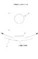
図1に本発明の参考例を示す。この参考例は、例えば玩具ロボットの姿勢検出に使用可能なように構成されたものであり、傾斜センサは合成樹脂材等の絶縁材料により形成される半球状のシェル8を有する。シェル8には球面からなる湾曲凹部3が形成されており、該湾曲凹部3に可動導体4が移動自在に収容される。
【0021】
上記湾曲凹部3の内壁面には最下部から同心円状に基準電極1と検出用電極2が交互にパターン形成される。上記基準電極1はグランドに接続されるとともに、各検出用電極2には抵抗Rを介して所定電圧が印可され、各抵抗Rには個別に抵抗Rによる電圧降下を検出するための端子20が引き出される。
【0022】
一方、可動導体4は水銀であり、自重で変形して湾曲凹部3に沿う形状となった際に、湾曲凹部3への接触面(導電性接触部40)が少なくともいずれかの基準電極1と検出用電極2を跨架する程度の大きさとなる程度の量が使用される。
【0023】
したがってこの参考例において、シェル8が傾くと可動導体4は、シェル8の傾斜角度に応じて湾曲凹部3の最下部から例えば図1において鎖線で示す位置に移動する。可動導体4の移動により該可動導体4の移動先の基準電極1と検出用電極2は可動導体4を介して短絡されることから、検出用電極2と基準電極1との間に電流iが流れて抵抗Rに端子間電圧Eが発生する。上記端子間電圧Eの発生は端子20の電位を検出部9において観察することにより監視されており、基準電極1と短絡した検出用電極2が特定される。
【0024】
一方、検出部9には各検出用電極2の設置位置情報が格納されており、上記特定された検出用電極2に対応する設置位置情報からシェル8の傾斜角度が導かれる。傾斜角度の精度は検出用電極2のピッチにより決定されるが、図3に示すように、湾曲凹部3の背面壁に形成される短絡用パターン21により上下に隣接する複数段(図3においては2段)毎を短絡させることにより、精度を任意に低下させることが可能であり、この場合には、端子20の数が減少するために、検出部9を始めとする全体構造が簡単になる。
【0025】
なお、図示の説明においては、いずれか一対の基準電極1と検出用電極2、2間を短絡する程度の大きさの可動導体4が使用されているが、複数対の基準電極1と検出用電極2間を短絡するものであってもよく、この場合には、短絡した最上段と最下段の検出用電極2の設置位置情報からシェル8の傾き動作角度が検出される。
【0026】
また、可動導体4としては、水銀のほかに図2に示すように、湾曲凹部3の曲率に合致する曲率を有する滑り面(導電性接触部40)を備えた円板体の使用が可能であるが、水銀を使用する場合には、検出部9において短絡する検出用電極2の数を同時に検出することにより、シェル8の傾き動作の角加速度の存在を知ることができる。
【0027】
すなわち、シェル8が等速角運動、あるいは静止状態から加速、あるいは減速した場合には、水銀は図4において鎖線で示すように、粘性、および慣性により見掛け上加速度発生方向と逆方向に延び、短絡する検出用電極2の数が増加するために、検出部9において短絡する検出用電極2の数の増減を検出することにより加速度の存在が検知される。さらに、図5に示すように、基準電極1と検出用電極2をリング状溝5の壁面に対向して形成した場合には、可動導体4として球体を使用することができる。
【0028】
図6に図1の変形例を示す。なお、以下の変形例、参考例、および実施の形態の説明において、上述した参考例と同一の構成要素は図中に同一符号を付して説明を省略する。
【0029】
この変形例において、各段の検出用電極2は周方向に分離される。各検出用電極2は個別に周方向の位置と、高さ方向の位置に関する設置位置情報を有しており、可動導体4により短絡された検出用端子20を特定することによりシェル8の傾く方向、および傾き角度の双方が検出できる。
【0030】
図7に本発明の第2の参考例を示す。この参考例において、湾曲凹部3の内壁面には電極対6が全面に渡って散点状に配置される。電極対6は内壁面にパターン形成される基準電極1と、基準電極1の周囲を包囲するリング状の検出用電極2とからなり、隣接する電極対6の間に絶縁体からなる中高部60が形成されて可動導体4をいずれかの電極対6に導く。
【0031】
したがってこの参考例において、シェル8が傾くと球状の可動導体4がいずれかの電極対6に導かれて当該電極対6の基準電極1と検出用電極2が短絡する。なお、図7においては可動導体4として球状のものを使用した場合が示されているが、水銀等の液状金属を使用することも可能である。また、電極対6は、図7に示す以外にも、例えば図8に示すように、基準電極1と検出用電極2を対向させるように配置することも可能である。
【0032】
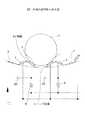
図9に本発明の実施の形態を示す。この実施の形態において、湾曲凹部3の内壁面にはV字状のガイド溝7が最下部から放射状に形成され、対向壁面に基準電極1と検出用電極2が形成される。ガイド溝7は湾曲凹部3の最下部において互いに鋭角に突き合わせられており、シェル8が傾いた際には可動導体4をいずれかのガイド溝7に導く。各ガイド溝7に形成される検出用電極2は所定の長さを有しており、隣接する他の検出用電極2との間に絶縁部22が形成される。
【0033】
したがってこの実施の形態において、シェル8が傾くと可動導体4はいずれかのガイド溝7内を移動して対向する検出用電極2と基準電極1間を短絡させる。なお、可動導体4を球状に形成する場合には、図9(c)に示すように、絶縁部22を突起形状に形成することによって可動導体4をいずれかの検出用電極2に導くようにするのが望ましい。
【0034】
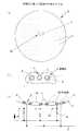
図10に本発明の第3の参考例を示す。この参考例はシェル8の傾き方向のみが検出可能なもので、湾曲凹部3の内壁面には最下部から放射状に基準電極1と検出用電極2が交互にパターン形成され、水銀、あるいは図2に示す円板体からなる可動導体4の移動により隣接する基準電極1と検出用電極2間を短絡する。
【0035】
なお、この参考例において、基準電極1と検出用電極2との間隔は湾曲凹部3の上辺に行くに従って広くなるために、可動導体4は、上辺近傍において基準電極1と検出用電極2間を短絡させることができるに十分な湾曲凹部3の内壁面との接触面積を有するように形成される。
【0036】
【発明の効果】
以上の説明から明らかなように、本発明によれば、構造が簡単で、かつ、要求精度等に応じて製造コストも低減させることができる。
【0039】
また、湾曲凹部の内壁面に、湾曲凹部の最下部から放射状に配置されて可動導体をガイドするガイド溝を形成することにより、必要に応じて測定精度を調整することができ、しかも、可動導体に球体を使用することが可能になる。
【図面の簡単な説明】
【図1】 本発明の参考例を示す図で、(a)は斜視図、(b)は湾曲凹部の上方から見た図である。
【図2】 可動導体の変形性を示す図で、(a)は平面図、(b)は側面図である。
【図3】 図1の変形例を示す図である。
【図4】 水銀による加速度の検出を示す図で、(a)は湾曲凹部の上方から見た図、(b)は水銀の初期状態と加速度が加わって変形した状態を示す図である。
【図5】 図1の他の変形例を示す図である。
【図6】 図1のさらに他の変形例を示す図である。
【図7】 本発明の第2の参考例を示す図で、(a)は湾曲凹部の上方から見た図、(b)は(a)の7B部拡大図、(c)は(b)の断面図である。
【図8】 図7の変形例を示す図で、(a)は図7(b)に対応する図、(b)は(a)の断面図である。
【図9】 本発明を示す図で、(a)は湾曲凹部の上方から見た図、(b)は(a)の9B-9B線断面図、(c)は絶縁部をガイド溝に沿って切断した断面図である。
【図10】 本発明の第3の参考例を示す図である。
【符号の説明】
1 基準電極
2 検出用電極
3 湾曲凹部
4 可動導体
40 導電性接触部
5 リング状溝
51 稜線
6 電極対
60 中高部
7 ガイド溝[0001]
BACKGROUND OF THE INVENTION
The present invention relates to a tilt sensor.
[0002]
[Prior art]
As a tilt sensor for measuring the tilt of various devices or the like, for example, a sensor described in JP-A-62-222104 is known. This inclination sensor is formed by storing mercury in a small container in which a resistance lead is disposed, and the change in the effective length of the resistance lead due to the inclination of the small container is detected by a resistance measuring instrument and measured by the resistance measuring instrument. An inclination angle or the like is detected from the value.
[0003]
[Problems to be solved by the invention]
However, in the above-described conventional example, the inclination angle and the like are determined by the analog value output from the resistance conductor, so that the peripheral circuit becomes complicated and a resistance conductor whose specific resistance is accurately controlled is used. Since it needs to be used, it has a drawback that the cost is likely to increase.
[0004]
Further, since the resistance value of the resistance conducting wire changes due to a change in temperature, it is necessary to compensate the resistance value, resulting in a disadvantage that the apparatus becomes large.
In addition, the tilt sensor requires a minimum of controlled resistance wires and resistance measuring instruments, and the minimum cost of the system is high, so the cost of the device is high even when high measurement accuracy is not required depending on the measurement target. Has the disadvantage of becoming.
[0005]
The present invention has been made to solve the above-described drawbacks, and an object of the present invention is to provide an inclination sensor that has a simple structure and can reduce the manufacturing cost in accordance with the required accuracy.
[0006]
[Means for Solving the Problems]
According to the present invention, the object is
A
A
Aninclination sensor that detects an inclination operation of the
A
This is achieved by providing an inclination sensorin which the
[0007]
The inner wall surface of the
[0008]
On the other hand, a
[0009]
Therefore, according to the present invention, when the
[0010]
Since the tilt sensor according to the present invention detects the tilting operation by detecting the presence or absence of a short circuit of each
[0017]
The tilt sensor includes a
[0018]
In this invention, the pitch of the
[0019]
In the present specification, unless otherwise specified, the lowermost portion indicates the lowermost portion in a state where the curved
[0020]
FIG. 1 shows areference example of the present invention. Thisreference example is configured to be used for detecting the posture of a toy robot, for example, and the tilt sensor has a
[0021]
On the inner wall surface of the
[0022]
On the other hand, the
[0023]
Therefore, in thisreference example , when the
[0024]
On the other hand, the installation position information of each
[0025]
In the illustrated description, the
[0026]
In addition to mercury, as the
[0027]
That is, when the
[0028]
FIG. 6 shows a modification of FIG. In the following description of the modification, thereference example, and the embodiment, the same components as those in thereference example described above are denoted by the samereference numerals in the drawings, and the description thereof is omitted.
[0029]
In this modification, the
[0030]
FIG. 7 shows a secondreference example of the present invention. In thisreference example , electrode pairs 6 are arranged in a dotted pattern over the entire surface on the inner wall surface of the
[0031]
Therefore, in thisreference example , when the
[0032]
Shows theimplementation of the embodimentof the present invention in FIG. In this embodiment, V-shaped
[0033]
Therefore, in this embodiment, when the
[0034]
FIG. 10 shows athird reference example ofthe present invention. In thisreference example, only the tilt direction of the
[0035]
In thisreference example , since the distance between the
[0036]
【The invention's effect】
As is apparent from the above description, according to the present invention, the structure is simple and the manufacturing cost can be reduced according to the required accuracy.
[0039]
Moreover, by forminga guide groove that is radially arranged on the inner wall surface of the curved concave portion from the lowermost portion of the curved concave portion and guides the movable conductor, the measurement accuracy can be adjusted as necessary. It becomes possible to use a sphere.
[Brief description of the drawings]
1A and 1B are diagrams showinga reference example of the present invention, in which FIG. 1A is a perspective view and FIG.
2A and 2B are diagrams showing the deformability of a movable conductor, in which FIG. 2A is a plan view and FIG. 2B is a side view.
FIG. 3 is a diagram showing a modification of FIG. 1;
4A and 4B are diagrams showing detectionof accelerationby mercury, wherein FIG. 4A is a view seen from above a curved concave portion, and FIG. 4B is a diagram showing an initial state of mercury and a deformed state due to acceleration.
FIG. 5 is a diagram showing another modification of FIG. 1;
6 is a diagram showing still another modification of FIG. 1. FIG.
7A and 7B are views showing a secondreference example of the present invention, in which FIG. 7A is a view as seen from above the curved concave portion, FIG. 7B is an enlarged view of a
8A and 8B are diagrams showing a modification of FIG. 7, in which FIG. 8A corresponds to FIG. 7B, and FIG. 8B is a cross-sectional view of FIG.
[9] a view showingthe present onsetbright, (a) represents a view from above of the curved recess, (b) the
FIG. 10 is a diagram showing athird reference example ofthe present invention.
[Explanation of symbols]
DESCRIPTION OF
Claims (1)
Translated fromJapanese湾曲凹部内で移動自在で、基準電極といずれかの検出用電極間を短絡可能な可動導体とを有し、
可動導体を介して基準電極に短絡した検出用電極の設置位置情報から湾曲凹部の傾き動作を検出する傾斜センサであって、
前記湾曲凹部の内壁面には、湾曲凹部の最下部から放射状に配置されて可動導体をガイドするガイド溝が形成され、
該ガイド溝内に基準電極と検出用電極を配置した傾斜センサ。A curved recess that is adjacent to a reference electrode maintained at a predetermined potential in a non-conductive state and includes a plurality of detection electrodes maintained on a potential different from the potential of the reference electrode on the inner wall surface;
A movable conductor that is movable within the curved recess and capable of short-circuiting between the reference electrode and one of the detection electrodes,
Aninclination sensor that detects the inclination operation of the curved recess from the installation position information of the detection electrode short-circuited to the reference electrode via the movable conductor,
On the inner wall surface of the curved recess, a guide groove that is radially arranged from the lowermost portion of the curved recess and guides the movable conductor is formed,
An inclination sensorin which a reference electrode and a detection electrode are arranged in the guide groove .
Priority Applications (1)
| Application Number | Priority Date | Filing Date | Title |
|---|---|---|---|
| JP18284497AJP3644799B2 (en) | 1997-07-08 | 1997-07-08 | Tilt sensor |
Applications Claiming Priority (1)
| Application Number | Priority Date | Filing Date | Title |
|---|---|---|---|
| JP18284497AJP3644799B2 (en) | 1997-07-08 | 1997-07-08 | Tilt sensor |
Publications (2)
| Publication Number | Publication Date |
|---|---|
| JPH1123266A JPH1123266A (en) | 1999-01-29 |
| JP3644799B2true JP3644799B2 (en) | 2005-05-11 |
Family
ID=16125454
Family Applications (1)
| Application Number | Title | Priority Date | Filing Date |
|---|---|---|---|
| JP18284497AExpired - Fee RelatedJP3644799B2 (en) | 1997-07-08 | 1997-07-08 | Tilt sensor |
Country Status (1)
| Country | Link |
|---|---|
| JP (1) | JP3644799B2 (en) |
Families Citing this family (7)
| Publication number | Priority date | Publication date | Assignee | Title |
|---|---|---|---|---|
| US6548771B1 (en)* | 1999-08-12 | 2003-04-15 | Seiko Instruments Inc. | Multipole attitude detector switch with liquid contact |
| DE102013108512A1 (en)* | 2013-08-07 | 2015-02-12 | Eberhard Karls Universität Tübingen | Apparatus and method for measuring the elasticity of a macroscopic sample |
| JP6539126B2 (en)* | 2015-06-22 | 2019-07-03 | 独立行政法人国立高等専門学校機構 | Swing detection drive device and swing detection drive method |
| CN107121130A (en)* | 2017-06-27 | 2017-09-01 | 贵州省质安交通工程监控检测中心有限责任公司 | A kind of side slope multi-angle offsets monitoring early-warning device |
| CN107314758B (en)* | 2017-09-01 | 2023-06-20 | 贵州省质安交通工程监控检测中心有限责任公司 | Slope deviation monitoring device and monitoring method |
| JP6779537B2 (en)* | 2019-05-15 | 2020-11-04 | 独立行政法人国立高等専門学校機構 | Shake detection drive device and shake detection drive method |
| CN113310465A (en)* | 2021-05-06 | 2021-08-27 | 湖北工业大学 | Inclination measuring device and inclination measuring method capable of simultaneously measuring angle and direction |
- 1997
- 1997-07-08JPJP18284497Apatent/JP3644799B2/ennot_activeExpired - Fee Related
Also Published As
| Publication number | Publication date |
|---|---|
| JPH1123266A (en) | 1999-01-29 |
Similar Documents
| Publication | Publication Date | Title |
|---|---|---|
| US4279080A (en) | Touch signalling probe | |
| US5955713A (en) | Tilt switch array for electronic orientation detection | |
| US4136458A (en) | Bi-axial probe | |
| US4629957A (en) | Sensing apparatus | |
| US5487305A (en) | Three axes accelerometer | |
| JP3644799B2 (en) | Tilt sensor | |
| JPH05502730A (en) | capacitive sensing probe | |
| JP4270647B2 (en) | Inclinometer | |
| US5625955A (en) | Tilt sensor | |
| KR840006411A (en) | Remote display of each location | |
| US3764820A (en) | Digital accelerometer | |
| US20100307247A1 (en) | Micromechanical acceleration sensor and method for manufacturing an acceleration sensor | |
| US10888276B2 (en) | Living body-attachable electrode | |
| US6496013B1 (en) | Device for testing circuit boards | |
| JP4397508B2 (en) | Nozzle capacitance detection method, nozzle capacitance detection sensor, and nozzle of laser processing machine | |
| EP3352063A1 (en) | Operation device | |
| US5819429A (en) | Touch sensor | |
| US12422315B2 (en) | Load sensor | |
| JPH075419Y2 (en) | Surface resistance measuring device | |
| JP2011163889A (en) | Pressure sensor device | |
| JPH0666825A (en) | Acceleration sensor | |
| RU2117299C1 (en) | Acceleration overload detector | |
| WO2006068194A1 (en) | Pressure sensitive sensor and pressure sensitive element | |
| SU1404803A1 (en) | Variable-capacitance transducer for checking thickness of wire insulation | |
| JP2933619B1 (en) | Motion sensor and motion sensor |
Legal Events
| Date | Code | Title | Description |
|---|---|---|---|
| A977 | Report on retrieval | Free format text:JAPANESE INTERMEDIATE CODE: A971007 Effective date:20040927 | |
| A131 | Notification of reasons for refusal | Free format text:JAPANESE INTERMEDIATE CODE: A131 Effective date:20041102 | |
| A521 | Written amendment | Free format text:JAPANESE INTERMEDIATE CODE: A523 Effective date:20041221 | |
| TRDD | Decision of grant or rejection written | ||
| A01 | Written decision to grant a patent or to grant a registration (utility model) | Free format text:JAPANESE INTERMEDIATE CODE: A01 Effective date:20050201 | |
| A61 | First payment of annual fees (during grant procedure) | Free format text:JAPANESE INTERMEDIATE CODE: A61 Effective date:20050201 | |
| R150 | Certificate of patent or registration of utility model | Free format text:JAPANESE INTERMEDIATE CODE: R150 | |
| FPAY | Renewal fee payment (event date is renewal date of database) | Free format text:PAYMENT UNTIL: 20080210 Year of fee payment:3 | |
| FPAY | Renewal fee payment (event date is renewal date of database) | Free format text:PAYMENT UNTIL: 20090210 Year of fee payment:4 | |
| FPAY | Renewal fee payment (event date is renewal date of database) | Free format text:PAYMENT UNTIL: 20090210 Year of fee payment:4 | |
| FPAY | Renewal fee payment (event date is renewal date of database) | Free format text:PAYMENT UNTIL: 20100210 Year of fee payment:5 | |
| FPAY | Renewal fee payment (event date is renewal date of database) | Free format text:PAYMENT UNTIL: 20110210 Year of fee payment:6 | |
| FPAY | Renewal fee payment (event date is renewal date of database) | Free format text:PAYMENT UNTIL: 20110210 Year of fee payment:6 | |
| FPAY | Renewal fee payment (event date is renewal date of database) | Free format text:PAYMENT UNTIL: 20120210 Year of fee payment:7 | |
| FPAY | Renewal fee payment (event date is renewal date of database) | Free format text:PAYMENT UNTIL: 20130210 Year of fee payment:8 | |
| FPAY | Renewal fee payment (event date is renewal date of database) | Free format text:PAYMENT UNTIL: 20130210 Year of fee payment:8 | |
| FPAY | Renewal fee payment (event date is renewal date of database) | Free format text:PAYMENT UNTIL: 20140210 Year of fee payment:9 | |
| LAPS | Cancellation because of no payment of annual fees |