JP3644111B2 - Tape label production equipment - Google Patents
Tape label production equipmentDownload PDFInfo
- Publication number
- JP3644111B2 JP3644111B2JP01508296AJP1508296AJP3644111B2JP 3644111 B2JP3644111 B2JP 3644111B2JP 01508296 AJP01508296 AJP 01508296AJP 1508296 AJP1508296 AJP 1508296AJP 3644111 B2JP3644111 B2JP 3644111B2
- Authority
- JP
- Japan
- Prior art keywords
- tape
- printing
- ribbon
- cassette
- Prior art date
- Legal status (The legal status is an assumption and is not a legal conclusion. Google has not performed a legal analysis and makes no representation as to the accuracy of the status listed.)
- Expired - Lifetime
Links
- 238000004519manufacturing processMethods0.000titleclaimsdescription3
- 238000007639printingMethods0.000claimsdescription199
- 238000001514detection methodMethods0.000claimsdescription83
- 230000007246mechanismEffects0.000claimsdescription40
- 239000003086colorantSubstances0.000claimsdescription22
- 238000012546transferMethods0.000claimsdescription22
- 230000007723transport mechanismEffects0.000claimsdescription8
- 238000013500data storageMethods0.000claimsdescription5
- 238000005520cutting processMethods0.000description78
- 238000000034methodMethods0.000description49
- 230000008569processEffects0.000description47
- 238000007651thermal printingMethods0.000description12
- 238000004886process controlMethods0.000description11
- 238000000926separation methodMethods0.000description10
- 238000012545processingMethods0.000description9
- 238000010586diagramMethods0.000description6
- 238000012790confirmationMethods0.000description5
- 238000004804windingMethods0.000description4
- 239000002131composite materialSubstances0.000description3
- 238000013461designMethods0.000description3
- 230000000694effectsEffects0.000description3
- 238000003825pressingMethods0.000description3
- 238000011144upstream manufacturingMethods0.000description3
- 102100033806Alpha-protein kinase 3Human genes0.000description2
- 101710082399Alpha-protein kinase 3Proteins0.000description2
- 239000004973liquid crystal related substanceSubstances0.000description2
- 230000004044responseEffects0.000description2
- 230000001154acute effectEffects0.000description1
- 238000013459approachMethods0.000description1
- 238000004364calculation methodMethods0.000description1
- 238000012840feeding operationMethods0.000description1
- 230000006870functionEffects0.000description1
- 238000012986modificationMethods0.000description1
- 230000004048modificationEffects0.000description1
- 230000002093peripheral effectEffects0.000description1
- 238000003860storageMethods0.000description1
- 239000010409thin filmSubstances0.000description1
- 230000032258transportEffects0.000description1
- 239000002699waste materialSubstances0.000description1
Images


Classifications
- B—PERFORMING OPERATIONS; TRANSPORTING
- B41—PRINTING; LINING MACHINES; TYPEWRITERS; STAMPS
- B41J—TYPEWRITERS; SELECTIVE PRINTING MECHANISMS, i.e. MECHANISMS PRINTING OTHERWISE THAN FROM A FORME; CORRECTION OF TYPOGRAPHICAL ERRORS
- B41J35/00—Other apparatus or arrangements associated with, or incorporated in, ink-ribbon mechanisms
- B41J35/16—Multicolour arrangements
- B41J35/18—Colour change effected automatically
- B—PERFORMING OPERATIONS; TRANSPORTING
- B41—PRINTING; LINING MACHINES; TYPEWRITERS; STAMPS
- B41J—TYPEWRITERS; SELECTIVE PRINTING MECHANISMS, i.e. MECHANISMS PRINTING OTHERWISE THAN FROM A FORME; CORRECTION OF TYPOGRAPHICAL ERRORS
- B41J15/00—Devices or arrangements of selective printing mechanisms, e.g. ink-jet printers or thermal printers, specially adapted for supporting or handling copy material in continuous form, e.g. webs
- B41J15/04—Supporting, feeding, or guiding devices; Mountings for web rolls or spindles
- B41J15/044—Cassettes or cartridges containing continuous copy material, tape, for setting into printing devices
- B—PERFORMING OPERATIONS; TRANSPORTING
- B41—PRINTING; LINING MACHINES; TYPEWRITERS; STAMPS
- B41J—TYPEWRITERS; SELECTIVE PRINTING MECHANISMS, i.e. MECHANISMS PRINTING OTHERWISE THAN FROM A FORME; CORRECTION OF TYPOGRAPHICAL ERRORS
- B41J3/00—Typewriters or selective printing or marking mechanisms characterised by the purpose for which they are constructed
- B41J3/407—Typewriters or selective printing or marking mechanisms characterised by the purpose for which they are constructed for marking on special material
- B41J3/4075—Tape printers; Label printers
- B—PERFORMING OPERATIONS; TRANSPORTING
- B41—PRINTING; LINING MACHINES; TYPEWRITERS; STAMPS
- B41J—TYPEWRITERS; SELECTIVE PRINTING MECHANISMS, i.e. MECHANISMS PRINTING OTHERWISE THAN FROM A FORME; CORRECTION OF TYPOGRAPHICAL ERRORS
- B41J32/00—Ink-ribbon cartridges
- B—PERFORMING OPERATIONS; TRANSPORTING
- B41—PRINTING; LINING MACHINES; TYPEWRITERS; STAMPS
- B41J—TYPEWRITERS; SELECTIVE PRINTING MECHANISMS, i.e. MECHANISMS PRINTING OTHERWISE THAN FROM A FORME; CORRECTION OF TYPOGRAPHICAL ERRORS
- B41J33/00—Apparatus or arrangements for feeding ink ribbons or like character-size impression-transfer material
- B41J33/14—Ribbon-feed devices or mechanisms
- B41J33/40—Ribbon-feed devices or mechanisms with arrangements for reversing the feed direction
- B41J33/44—Ribbon-feed devices or mechanisms with arrangements for reversing the feed direction automatically
Landscapes
- Printers Characterized By Their Purpose (AREA)
- Impression-Transfer Materials And Handling Thereof (AREA)
- Handling Of Continuous Sheets Of Paper (AREA)
- Record Information Processing For Printing (AREA)
Description
Translated fromJapanese【0001】
【発明の属する技術分野】
本発明は、テープ状ラベル作成装置に関し、特に同一印字領域を繰り返して印字する為に、印字したテープを巻き戻すときに、リボンカセットのインクリボンの巻き戻しを防止するようにしたものに関する。
【0002】
【従来の技術】
従来、本願出願人は、特開平5−84994号公報に記載のように、印字媒体である印字テープに文字や記号のキャラクタやマークを印字し、ファイルの背表紙に貼付するのに適したラベルを作成するのに好適なテープ状ラベル作成装置を提案し、実用化した。このラベル作成装置は、キーボード、ディスプレイ、サーマル印字方式の印字機構を備え、印字媒体としての印字テープ(例えば、テープ幅6、9、12、18、24mm)に、キャラクタやマークを、種々の文字サイズや書体で印字できるように構成してある。
【0003】
ところで、印字テープを送り方向だけでなく、巻き戻し方向にも移送可能に構成し、例えば、文字や記号を印字テープに1回目として印字した後、その印字テープを1回目の印字開始位置まで巻き戻して、更に文字や記号を重複させて2回目の印字を実行することで、合成文字やデザイン模様を印字したテープ状のラベルを作成することが考えられる。
【0004】
また、文字印字により作成したテープ状のラベルは、ファイルの背表紙だけに限らず、例えば、カセットテープやそのカセットテープケース、更にはビデオテープやそのビデオテープケースに貼付するのにも好適であり、印字処理と印字テープの巻き戻しとを繰り返すことで、収録内容やジャンルに応じて、印字文字列をカラフルに多色印字したテープ状のラベルを作成することが考えられる。
【0005】
そこで、本願の発明者達は、インクリボンのリボン色を、「黒」だけでなく、「赤」や「緑」や「青」・・などの複数色とする複数種類のリボンカセットをテープカセットとは別体のものとして準備し、これらリボンカセットをテープカセットに対して着脱可能に構成するとともに、多色印字に供する印字色を、印字する順序に順次設定する一方、入力したテキストに対して、設定した複数色で印字する各印字色毎の印字対象範囲を設定する色別範囲設定処理を実行するようにし、設定した印字色と同様のリボン色を有するリボンカセットを順次取り替えて印字処理するとともに、各印字処理毎に印字テープを印字開始位置まで巻き戻し制御することで、合成文字やデザイン模様を印字したラベルを作成したり、複数色でカラフルに多色印字したラベルを作成することに着想した。
【0006】
【発明が解決しようとする課題】
ここで、リボンカセットには、インクリボンを巻装したリボンスプールと、インクリボンを巻き取るリボン巻き取りスプールとが設けられ、一般的に、印字テープの送り動作と連動してリボン巻き取りスプールだけを巻き取り駆動することで、印字したインクリボンを巻き取るようになっている。
【0007】
本願の発明者達が着想したように、合成文字やデザイン模様を印字したラベルや、複数色でカラフルに多色印字したラベルを作成する為に、1つのリボンカセットを用いて、或いはリボン色の異なるリボンカセットを順次取り替えて印字処理するとともに、各印字処理毎に印字テープを印字開始位置まで巻き戻し制御する場合、印字テープの巻き戻し時に、その巻き戻しに連動して、リボンカセット内のリボン巻き取りスプールを巻き取りと反対に巻き戻し駆動したときには、リボン巻き取りスプールに巻装されたインクリボンが多量に繰り出されてリボンカセット内に絡まることになるので、印字テープの巻き戻し時には、その巻き戻しに連動してリボン巻き取りスプールを駆動させないような、連動解除機構を別途設けることになり、サーマル印字機構が複雑化且つ大型化するという問題がある。
【0008】
また、リボンカセットを交換する際に、使用者が不用意にキーボードの取消キーを操作してしまうと、多色印字の途中にもかかわらず印字が中断してしまい、印字済みのテープが無駄になるという問題がある。
【0009】
本発明は、上述した問題点を解決するためになされたものであり、テープ移送機構によるテープの巻き戻し時に、その巻き戻しに連動してリボンカセット内のリボン巻き取りスプールを巻き戻し駆動させない連動解除機構を何ら設けることなく、インクリボンの巻き戻しを防止し得ると共に、リボンカセット交換中に不用意な入力手段のキー入力操作により印字が中断しないようなテープ状ラベル作成装置を提供することにある。
【0010】
【課題を解決するための手段】
この目的を達成するために、請求項1記載のテープ状ラベル作成装置は、文字や記号及び種々の指令を入力する為の入力手段と、入力されたテキストのデータを記憶するデータ記憶手段と、ディスプレイを含む表示手段と、印字媒体であるテープを送り方向と巻き戻し方向とに択一的に移送するテープ移送機構と、インクリボンを収容し着脱自在に装着されるリボンカセットと、リボンカセットの装着の有無を検出するカセット検出手段と、テープに印字する印字ヘッドを含む印字手段と、印字の為の制御を司る制御手段とを備えたテープ状ラベル作成装置であって、前記カセット検出手段がリボンカセットが外されたことを検知しているときに、前記入力手段からキー入力されると、テープ移送機構によるテープの印字開始位置までテープの巻き戻しを自動的に実行させるテープ巻き戻し制御手段を備えている。
【0011】
上記のように構成された請求項1に係るテープ状ラベル作成装置においては、入力手段で入力されたテキストのデータがデータ記憶手段に記憶されると、制御手段は印字手段に対して印字制御を司るので、印字手段の印字ヘッドは装着されたリボンカセットのインクリボンを介してテープに印字する。そして、テープの巻き戻しに際しては、テープ巻き戻し制御手段は、カセット検出手段の検出信号からリボンカセットが外されたことを検知しているときに、入力手段からキー入力されると、テープ移送機構にテープを巻き戻し方向へ移送させる。
【0012】
また、請求項2記載のテープ状ラベル作成装置は、文字や記号及び種々の指令を入力する為の入力手段と、入力されたテキストのデータを記憶するデータ記憶手段と、ディスプレイを含む表示手段と、印字媒体であるテープを送り方向と巻き戻し方向とに択一的に移送するテープ移送機構と、複数色のインクリボンを夫々収容し且つ複数色で順々に印字する為に着脱自在に択一的に装着される複数のリボンカセットと、リボンカセットの装着の有無を検出するカセット検出手段と、テープに印字する印字ヘッドを含む印字手段と、印字の為の制御を司る制御手段とを備えたテープ状ラベル作成装置であって、前記カセット検出手段がリボンカセットが外されたことを検知しているときに、前記入力手段からキー入力されると、テープ移送機構によるテープの印字開始位置までテープの巻き戻しを自動的に実行させるテープ巻き戻し制御手段を備えている。
【0013】
上記のように構成された請求項2に係るテープ状ラベル作成装置においては、請求項1と略同様に作用する。即ち、各印字処理の終了毎に、複数色印字の為に準備された複数のリボンカセットのうちから択一的に装着されたリボンカセットが取り外されたのを検知しているときに、入力手段からキー入力されると、テープ巻き戻し制御手段がテープ移送機構によるテープの巻き戻し方向への移送を実行する。
【0014】
また、請求項3に記載のテープ状ラベル作成装置は、請求項1または請求項2と同様の構成を有するが、前記テープ巻き戻し制御手段が、入力手段からの任意のキー入力によりテープ移送機構にテープの巻き戻しを自動的に実行させる。
【0015】
また、請求項4に記載のテープ状ラベル作成装置は、請求項1または請求項2と同様の構成を有するが、前記テープ巻き戻し制御手段は、入力手段からの特定のキー入力のみによりテープ移送機構にテープの巻き戻しを自動的に実行させる。
【0016】
また、請求項5に記載のテープ状ラベル作成装置は、請求項1または請求項2と同様の構成を有するが、前記テープ移送機構のテープ移送経路の終端付近においてテープの有無を検出するテープ検出手段を設け、前記テープ巻き戻し制御手段はテープ検出手段の検出信号からテープの先端を検出したときに、テープの巻き戻しを停止する。
【0017】
【発明の実施の形態】
以下、本発明の実施の形態について図面を参照して説明する。
【0018】
本実施形態は、文字や記号などの多数のキャラクタを印字媒体である印字テープに、リボン色の異なる複数のリボンカセットを取り換えることで、多色印字可能なテープ状ラベル作成装置に本発明を適用した場合のものである。
【0019】
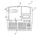
図1に示すように、テープ状ラベル作成装置1の本体カバー2の前部には、文字や記号や数字などの文字キーに加えて、種々の機能キーなどが設けられたキーボード4が配設され、そのキーボード4の直ぐ後側には、入力した文字や記号を表示可能な液晶ディスプレイ5が設けられるとともに、リボンカセット30の交換時に開閉されるカセットカバー3に対応する本体カバー2の内部には、サーマルヘッド12を備えたサーマル印字機構10が配設されている。ここで、スライドツマミ6をスライドさせてカセットカバー3を開放でき、また切断用ノブ85を下方に押圧操作して、印字した印字テープ22を手動で切断できる。
【0020】
次に、サーマルヘッド12を含むサーマル印字機構10について、図2〜図8に基づいて説明する。
【0021】
先ず、サーマル印字機構10に着脱可能に装着されるテープカセット20について、図2〜図5・図7に基づいて説明する。
【0022】
このテープカセット20のテープケース21内部には、薄膜状のフィルムからなる印字テープ22が巻装されたテープスプール23が回転自在に設けられ、このテープスプール23から繰出された印字テープ22は、複数のガイド部で湾曲状にガイドされて、サーマルヘッド12の直前を通過して、テープ送りローラ24によりテープ送り方向に移送されてテープカセット20の外部に排出されるように構成されている。
【0023】
また、図7に示すように、テープケース21の外周壁の相離隔した2箇所には、次に説明するリボンカセット30の着脱時に、リボンカセット30を上下方向にガイドし且つ支持する為の1対のガイド軸21a・21bの下端部が夫々一体形成されている。更に、テープケース21には、リボンカセット30の下側に当接して支持する1対の下端壁部21c・21dが夫々形成されている。
【0024】
次に、テープカセット20に着脱可能に装着されるリボンカセット30について、図2〜図8に基づいて説明する。
【0025】
リボンカセット30のリボンケース31には、テープケース21の一部分に上側から当接する上壁部31aが水平に延びて一体形成され、その上壁部31aの端部には、テープケース21の1対のガイド軸21a・21bに外嵌される、貫通穴を有する1対の係合脚部31b・31cが形成されるとともに、テープケース21の切欠き部21eに当接する垂直壁部31dが形成されている。また、リボンカセット30には、テープカセット20を挿通して下方から挿入されるサーマルヘッド12を収容するヘッド収容部37が形成されている。
【0026】
更に、リボンケース31内部には、インクリボン32が巻装されたリボンスプール33と、このインクリボン32を巻取るリボン巻取りスプール34とが回転可能に設けられ、リボンスプール33に巻装されたインクリボン32は、サーマルヘッド12に対向するときに印字テープ22と一時的に平行状に接近し、リボンケース31に一体形成された分離部材35の分離部35aで略鋭角的に折曲されて、印字テープ22から離間し、リボン巻取りスプール34で巻き取られるように構成されている。即ち、リボンケース31の分離部材35は、サーマルヘッド12のテープ送り方向下流側に位置している。そして、リボンケース31には、これらリボンスプール33、巻取りスプール34、分離部材35等を上側から支持する蓋部材31eが形成されている。
【0027】
一方、テープケース21には、リボンカセット30を収容する為のリボンカセット収容部21f(図7参照)が形成され、リボンケース31の蓋部材31eと上壁部31aとの上面には、つまみ片31f,31gが夫々形成されているので、印字に際しては、先ずテープケース21を本体カバー2に設けられた装着用凹部(図示略)に装着した後、所望の印字色のインクリボン32を有するリボンカセット30をテープケース21のリボンカセット収容部21fに装着することができる。
【0028】
このときには、先ず2本の指で1対のつまみ片31f,31gを掴んだ状態で、1対の係合脚部31b・31cを対応するガイド軸21a,21bに貫通穴を介して夫々外嵌させながら、リボンカセット30を下方に移動させてリボンカセット収容部21fに収納する。
【0029】
このとき、リボンケース31の上壁部31aがテープカセット20の上面に重なるとともに、リボンカセット30の下端部は、テープケース21の1対の下端壁部21c・21dに上側から当接して、リボンカセット30はテープケース21に対して所定位置に保持される。
【0030】
ところで、リボンカセット30には、インクリボン32のリボン色(赤、緑、黄、黒、・・・)やリボン幅(12、18、24、32mm) により、複数種類が準備されており、リボンケース31の垂直壁部31dの下端部には、これら複数種類のリボンカセット30の何れかを検出させる為に、最大で6つの検出穴36aを組合せた検出用穴群36(図6においては、1つの検出穴36aが形成されている)が形成されている。
【0031】
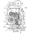
次に、印字テープ22とインクリボン32とを印字方向である送り方向と、反印字方向である巻き戻し方向とに移送可能なテープ・リボン移送機構40について、図9に基づいて説明する。
【0032】
本体フレーム11には、テープスプール23の中央部に係合可能なテープ巻取りカム41と、リボン巻取りスプール34の中央部に係合可能なリボン巻取りカム42と、テープ送りローラ24の中央部に係合するテープ駆動カム43とが回転可能に枢支され、サーマルヘッド12が立設されるとともに、前記検出用穴群36の6つの検出穴36aの有無を検出する為に、第1〜第6検出スイッチからなるリボン検出スイッチ群103が設けられ、これら6つの検出スイッチからのスイッチ信号の組み合わせによるリボン検出信号RSが出力される。ここで、そのリボン検出スイッチ群103と検出用穴群36などからカセット検出手段が構成されている。
【0033】
更に、本体フレーム11の前端部の右端部には、ステッピングモータからなるテープ駆動モータ44が取付けられ、このテープ駆動モータ44の駆動ギヤ45に、本体フレーム11に夫々回転可能に支持されたギヤ46〜53が順次噛み合い、このギヤ53には、テープ駆動カム43に固着されたテープ駆動ギヤ54とギヤ55とが噛み合っている。ここで、ギヤ48とギヤ49とは一体的に形成されて、リボン巻取りカム42の下端部に固着され、またギヤ50とギヤ51とは一体的に形成され、更にテープ巻取りギヤ52はテープ巻取りカム41の下端部に固着されている。即ち、テープ駆動モータ44の回転は、これらギヤ45〜54を介して、テープ駆動ギヤ54に固着されたテープ駆動カム43に伝達され、テープ送りローラ24の回転により印字テープ22が移送される。
【0034】
一方、一体形成された両ギヤ50,51の隙間には、揺動レバー56の基端部が両ギヤ50,51との間に適度の摩擦抵抗を付与された状態で支持され、その揺動レバー56には、ギヤ51に常時噛み合う遊星ギヤ57が回転可能に枢支されている。また、ギヤ53の枢支軸58には、切断禁止レバー84の基端部が、切断禁止レバー84に支持されている巻きバネ59の一端と基端部とで枢支軸58を挟むように、巻きバネ59の付勢力により押圧支持されている。
【0035】
そして、図9に示すように、テープ駆動モータ44が通常印字の為に、時計回転方向に駆動(正回転駆動)されて、ギヤ50が時計回転方向に回転するときには、両者間の摩擦力によりその揺動レバー56も時計回転方向に回動して、遊星ギヤ57がテープ巻取りギヤ52と噛合しないようになり、テープ巻取りカム41がフリーになることから、テープスプール23に巻装された印字テープ22が繰出されると同時に、ギヤ53が反時計回転方向に回転して、切断禁止レバー84が反時計回転方向に回動し、切断禁止レバー84の先端部が後述する切断用レバー82の下側に位置して、切断動作が禁止されるとともに、リボン駆動ギヤ45の反時計回転方向への回転によりリボン巻取りカム42がクラッチバネ60を介して反時計回転方向へ回転して、インクリボン32がリボン巻取りスプール34に巻取られる。
【0036】
ところで、ゴム製のプラテンローラ65とテープ送りサブローラ66とを回転可能に支持するローラホルダ67は、本体フレーム11に立設された枢支軸68に回動可能に枢支され、カセットカバー3の開閉に連動してリリースレバー71が左右方向に移動して、図9に示す印字位置と、図11に示すリリース位置とに亙って位置切換えされる。
【0037】
ここで、そのローラホルダ67は、図示外の巻きバネにより常にリリース位置に弾性付勢されている。即ち、リリースレバー71に枢着したコロ72が本体フレーム11の立設壁11aに当接するとともに、リリースレバー71の一端部がローラホルダ67に後側から当接しているので、リリースレバー71が図11に示す退避位置から図9に示す作動位置まで左方移動したときには、リリースレバー71の左端部がローラホルダ67と立設壁11aとの間にクサビ状に侵入して、ローラホルダ67はリリース位置から印字位置に切換えられる。
【0038】
このとき、プラテンローラ65は印字テープ22とインクリボン32とを介してサーマルヘッド12を押圧するとともに、テープ送りサブローラ66は印字テープ22を介してテープ送りローラ24を押圧している。
【0039】
ここで、ローラホルダ67が印字位置に切換えられたときには、プラテンローラ65の下端部に固着したプラテンギヤ(図示略)がギヤ55に噛合するとともに、またテープ送りサブローラ66の下端部に固着したサブローラギヤ(図示略)がテープ駆動ギヤ54に噛合する。
【0040】
次に、カセットカバー3の開放に連動してリリースレバー71を右方向に駆動して、ローラホルダ67をサーマルヘッド12に対してリリース位置に切換えてリリースさせるヘッドリリース機構70について、図9・図11〜図13に基づいて説明する。
【0041】
前記カセットカバー3の後端部は、図12〜図13に示すように、本体カバー2に取付けた枢支ピン7に複数箇所で開閉可能に支持され、そのカセットカバー3の右側壁3aには、湾曲状の溝カム3bが形成されている。そして、本体フレーム11の右端部の下側に配設された作動板74の後端部には、その溝カム3bに係合する係合ピン75が固着されている。ところで、リリースレバー71の右端部は、本体フレーム11に回動可能に枢着した二股レバー76の一方のレバーに回動可能に枢支されるとともに、その二股レバー76の他方のレバーには、作動板74の前端部に固着したピン77を介して連結されている。
【0042】
そして、図12に示すようにカセットカバー3が閉じているとき、つまりローラホルダ67が図9に示す印字位置のときに、図13に示すように、カセットカバー3を開放したときには、溝カム3bの移動により、この溝カム3bに係合する係合ピン75が後方に移動するので、作動板74が後方に移動し、二股レバー76が反時計回転方向に回動して、リリースレバー71が右方に移動するのに応動して、ローラホルダ67がリリース位置に切換えられる。このとき、作動板74が後方に移動したときに、カバー開閉検出スイッチ102から「H」レベルのカバー開閉信号VSが出力される。
【0043】
また、図13に示すようにカセットカバー3を開放しているとき、つまりローラホルダ67が図11に示すリリース位置のときに、図12に示すように、カセットカバー3を閉じたときには、溝カム3bの移動により、係合ピン75が前方に移動するので、作動板74が前方に移動し、二股レバー76が図11に示す位置から時計回転方向に回動して、リリースレバー71が左方に移動するのに応動して、ローラホルダ67が印字位置、つまり非リリース状態に切換えられる。
【0044】
そして、図2・図9に示すように、印字を実行する際には、先ずテープカセット20をサーマル印字機構10に装着した上で、このテープカセット20にリボンカセット30が装着され、カセットカバー3を閉じたときには、ローラホルダ67が印字位置に切換えられている。
【0045】
そして、この状態で、テープ駆動モータ44が通常印字方向に正回転駆動されたときには、これらギヤ45〜55が夫々所定の回転方向に駆動され、プラテンローラ65とテープ送りサブローラ66とが夫々反時計回転方向に回転されるとともに、テープ送りサブローラ66とテープ送りローラ24とが同期して回転するので、印字テープ22は、サーマルヘッド12で印字されながら、テープ切断機構80とテープ検出機構90とを通過して外部に排出される。このとき、テープ巻取りカム41がフリーになることから、テープスプール23に巻装された印字テープ22が抵抗なく順次繰出される。
【0046】
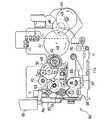
これと同時に、インクリボン32は、プラテンローラ65の回転により印字テープ22と同期してリボンスプール33から繰出され、リボン巻取りギヤ48の回転によりリボン巻取りカム42が回転され、リボン巻取りカム42に係合して回転するリボン巻取りスプール34に巻き取られる。
【0047】
一方、1色目の印字が終了して2色目印字を実行する際には、先ずカセットカバー3を開放して、リボンカセット30が取り外されたときには、ローラホルダ67はヘッドリリース機構70によりリリース位置に切換えられている。そして、テープ駆動モータ44が反時計回転方向(巻き戻し方向)に逆回転駆動されたときには、図3・図11に示すように、これらギヤ45〜55が夫々所定の回転方向に駆動される。このとき、ギヤ50の反時計回転方向への回転により、揺動レバー56も反時計回転方向に回動して、遊星ギヤ57がテープ巻取りギヤ52と噛合するようになり、テープ巻取りカム41が反時計回転方向に回転して、印字された印字テープ22がテープスプール23に巻取られる。ここで、リボン巻取りギヤ48が時計回転方向に回転駆動されるが、リボンカセット30が取り外されているので、リボン巻取りスプール34に巻取られたインクリボン32の繰出しはない。
【0048】
次に、印字された印字テープ22を切断するテープ切断機構80について、図9・図14・図15に基づいて説明する。
【0049】
本体フレーム11の左端部が部分的に下方に曲げられた左端壁11bには、固定刃81の下端部が固着され、側面視略L字状の切断用レバー82の基端部がビス83で回動可能に枢支され、その切断用レバー82には可動刃82aが形成されている。ここで、印字中には、図9に示すように、ギヤ53が反時計回転方向に回転して、切断禁止レバー84の先端部が切断用レバー82の下側に移動して、切断動作が禁止されている。
【0050】
しかし、印字終了時に、テープ駆動モータ44が少しだけ巻き戻し方向に回転されたときには、図15に示すように、ギヤ53が時計回転方向に少しだけ回転して、切断禁止レバー84の先端部が切断用レバー82の下側から外れて切断動作が可能になったときに、図14に示すように、切断用レバー82の先端部の切断用ノブ85を下方向に押圧操作したときには、可動刃82aが2点鎖線で示す切断位置に回動し、固定刃81と可動刃82aとの間に位置する印字テープ22が、これら両刃81・82aの協働により切断される。このとき、本体フレーム11に取付けられた切断検出スイッチ101は、切断用レバー82に取付けた作動部材86により作動して切断検出信号CSを出力する。そして、切断用レバー82の押圧操作を停止すると、切断用レバー82は、図示外のバネによる付勢力により、実線で示す元の所定位置に復帰回動する。
【0051】
次に、そのテープ切断機構80よりも外側に設けられ、印字テープ22の有無を検出するテープ検出機構90について、図2に基づいて説明する。
【0052】
テープ切断機構80よりも外側の本体カバー2には、1対のセンサ収容室96・97を密閉状に形成する為に案内部材94,95が一体的に形成され、一方のセンサ収容室96には発光素子92が取付けられるとともに、他方のセンサ収容室97には受光素子93が取付けられている。これら1対の案内部材94,95の間には、印字テープ22が通過可能なスリット98が形成されるとともに、1対の案内部材94,95の相対向する部位には、小径の光通過穴94a・95aが形成されるとともに、傾斜したガイド部99が夫々形成されて、テープ切断機構80を通過した印字テープ22の先端部をこのガイド部99でガイドすることで、確実にスリット98を通過して検出可能になっている。
【0053】
そして、発光素子92から発射されたセンサ光が、各センサ収容室96・97に形成された光通過穴94a・95aを通過して、受光素子93に投射される。即ち、印字テープ22が、テープ検出センサ91に進入し、その発光素子92と受光素子93との間に存在するときだけ、そのセンサ光が遮断されることから、テープ検出センサ91からは、「L」レベルのテープ検出信号TSが出力される。
【0054】
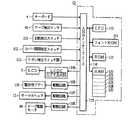
次に、テープ状ラベル作成装置1の制御系は、図16のブロック図に示すように構成されている。
【0055】
制御装置CDの入出力インターフェース113には、キーボード4と、テープ検出センサ91と、切断検出スイッチ101と、カバー開閉検出スイッチ102と、リボン検出スイッチ群103と、液晶ディスプレイ(LCD)5に表示データを出力する為のビデオRAMを有するディスプレイコントローラ(LCDC)104と、警告用ブザー105の為の駆動回路106と、サーマルヘッド12を駆動する為の駆動回路107と、テープ駆動モータ44の為の駆動回路108とが夫々接続されている。
【0056】
制御装置CDは、CPU110と、このCPU110にデータバスなどのバス114を介して接続された入出力インターフェース113と、フォントROM111と、ROM112及びRAM120とから構成されている。
【0057】
フォントROM111には、文字や記号などの多数のキャラクタの各々に関して、表示用ドットパターンデータが格納されるとともに、印字用ドットパターンデータが、複数の印字文字サイズ分格納されている。
【0058】
前記ROM112には、キーボード4から入力された文字や記号や数字などのキャラクタのコードデータに対応させて、ディスプレイコントローラ104を制御する表示駆動制御プログラム、テキストメモリ121に格納された文字や記号について、印字に供するドットパターンデータを作成する印字制御プログラムや、作成されたドットパターンデータについて、1ドット列毎のドットパターンデータを順次サーマルヘッド12やテープ駆動モータ44に出力して印字する印字駆動制御プログラム、本願特有の後述の多色印字制御の制御プログラムなどが格納されている。尚、ROM112には、第1〜第6検出スイッチからなるリボン検出スイッチ群103から出力されるリボン検出信号RSに基づいて、インクリボン32のリボン色とリボン幅とを検知するリボンカセット検知テーブルが格納されている。
【0059】
前記RAM120のテキストメモリ121には、キーボード4から入力された文字や記号からなるテキストのデータが、設定された印字色のデータを対応づけて格納される。色数メモリ122には、設定された印字色の色数データが格納される。印字色順序メモリ123には、設定された印字色の色順序のデータが格納される。余白量メモリ124には、設定された同一の前余白量と後余白量とに関する余白量データが格納される。印字データバッファ125には、そのテキストメモリ121に格納されたキャラクタコードに対応するドットパターンデータが展開して格納される。更に、RAM120には、CPU110で演算した演算結果を一時的に格納するメモリなどが設けられている。
【0060】
次に、テープ状ラベル作成装置1の制御装置CDで行なわれる、多色印字制御のルーチンについて、図17〜図25のフローチャートに基づいて説明する。尚、図中符号Si(i=10、11、12・・・)は各ステップである。
【0061】
ここで、多色印字制御に先立って、図26に基づいて、テープ検出センサ91によるテープ検出位置と、テープ切断機構80によるテープ切断位置と、サーマルヘッド12による印字位置との位置関係について説明すると、印字テープ22の送り方向Tにおいて、送り方向Tの上流側から印字位置(P位置)、テープ切断位置(C位置)テープ検出位置(S位置)の順となり、印字位置とテープ切断位置との印字・切断間距離Dcpは約25mmであり、テープ切断位置とテープ検出位置との切断・検出間距離Dscは約15mmである。また、分離部材35の分離部35aによる分離位置(B位置)は、送り方向Tにおいて印字位置よりも約6mmだけ下流側に位置している。
【0062】
このテープ状ラベル作成装置1に電源が投入されると、先ずサーマル印字機構10や制御装置CDを初期化する初期化処理が実行される(S10)。そして、ディスプレイ5には、テキスト入力画面が表示されるので、印字用書式を設定後、テキストのデータを入力する入力処理やその入力されたテキストを表示する表示処理が実行され、入力されたテキストデータはテキストメモリ121に格納される(S11)。例えば、図27に示すように、入力されたテキストデータ「あか みどり くろ」がテキストメモリ121に格納される。
【0063】
次に、印字色順序設定処理制御(図18参照)が実行される(S12)。
【0064】
この制御が開始されると、メッセージ「印字色数は?」がディスプレイ5に表示されるので、数字キーを操作して色数Nを設定する色数設定処理が実行され、その設定された色数Nが色数メモリ122に格納される(S30)。次に、複数の色の名前がディスプレイ5に表示されるので、印字に供する色の順序を順次設定する色順序設定処理が実行され、設定された色順序のデータが印字色順序メモリ123に格納され(S31)、この制御を終了して、多色印字制御のS13にリターンする。
【0065】
次に、多色印字制御において、色毎の印字対象範囲設定処理制御(図19参照)が実行される(S13)。
【0066】
この制御が開始されると、先ず色数カウンタのカウント値Iに色数Nがセットされ(S33)、この色数カウント値Iから「1」を減算して「0」でないとき、つまり最終の印字色の対象文字列の設定でないときには(S34:No)、色順序のデータに基づいて、未設定色のうち印字色順序における先頭印字色について、印字対象となる文字や記号の各々をカーソルで指示して設定する印字対象文字列設定処理が実行される(S35)。
【0067】
即ち、この印字対象文字列設定処理においては、テキストデータがディスプレイ5に表示されるので、キーボード4の右端に配置されている4つのカーソル移動キーを操作して、最終の印字色以外の各印字色について、印字対象となる文字や記号の各々をカーソル移動キーを操作してカーソルで指示すると共に、その都度色確定キーを操作し、印字対象文字列の設定終了時には、確定キーが操作される。この確定キーの操作により、カーソル移動キーと色確定キーとの操作により指示された文字の文字データに付随させて、設定された色データがテキストメモリ121に記憶される。
【0068】
そして、色数カウント値Iが1つデクリメントされ(S36)、(I−1)が「0」になるまで、S34〜S36が繰り返して実行される。そして、(I−1)が「0」になって、最終の印字色以外の各印字色について、印字対象文字列の設定が完了したときには(S34:Yes )、最終の印字色について、テキストデータのうち、既に設定された文字や記号を除く残りの文字を設定する文字列設定処理が実行される(S37)。
【0069】
この文字列設定処理を図20に基づいて具体的に説明すると、先ず、テキストメモリ121に記憶されている文字データが先頭から読み出され(S371 )、色データが付随しているか否かが判断される(S372 )。読み出された文字データに色データが付随しており(S372 :Yes )、その文字データが最後の文字データでなければ(S373 :No)、次のデータが読み出され(S374 )、前記S372 の処理が再度実行される。一方、読み出された文字データに色データが付随していなければ(S372 :No)、その文字データに対して、最終の印字色に対応する色データが付随して記憶され(S375 )、前記S373 の処理が実行される。上記各処理が、テキストメモリ121に記憶されている最後の文字データまで繰り返し実行され、前記S373 において、最後の文字データであると判断されると(S373 :Yes )、図19のS38へリターンする。
【0070】
例えば、テキストメモリ121に文字データ「あか みどり くろ」が記憶され、色数3、色順序「赤」「緑」「黒」が設定されていると、S35の印字対象文字列設定処理において、先ず、印字色「赤」については、カーソルキーと色確定キーの操作により文字列「あか」が設定され、図27に示すように、テキストメモリ121の文字データ「あ」「か」の各々に付随して色データ「赤」が記憶され、次に印字色「緑」について文字列「みどり」が設定されると、テキストメモリ121の文字データ「み」「ど」「り」の各々に付随して色データ「緑」が記憶される。
【0071】
ここで、印字色「緑」の設定が終了すると、色数カウント値(I−1)が「0」となるので、S37の文字列設定処理において、テキストメモリ121の先頭から順次文字データが読み出され、テキストデータの印字色が未設定の文字列「くろ」に対して最終の印字色「黒」が自動的に設定され、テキストメモリ121の文字データ「く」「ろ」に付随して色データ「黒」が記憶される。
【0072】
次に、ディスプレイ5にメッセージ「印字テープの余白量は?」が表示されるので、数字キーを操作して所望の余白量が設定されると、その設定された余白量が余白量メモリ124に記憶され(S38)、この制御を終了して、多色印字制御のS14にリターンする。
【0073】
そして、多色印字制御において、印字キーが操作されたときには(S14・S15:Yes )、印字開始処理制御(図21参照)が実行される(S16)。
【0074】
この制御が開始されると、先ずリボン検出スイッチ群103からのリボン検出信号RSに基づいて、装着されたリボンカセット30のリボン色Rが読み込まれ(S40)、印字色順序の先頭印字色Cが読み込まれ(S41)、リボン色Rと先頭印字色Cとが一致しないときは(S42:No)、印字色の不一致を知らせるエラーメッセージがディスプレイ5に表示される(S43)。
【0075】
次に、カバー開閉検出スイッチ102のカバー開閉信号VSに基づいて、カセットカバー3が開放されてリボンカセット30の交換後、再度カセットカバー3が閉じられたときには(S44:Yes )、S40〜S41が実行される。そして、リボン色Rと先頭印字色Cとが一致したときには(S42:Yes )、先頭印字色Cのデータを付随して記憶した文字列がテキストメモリ121から読み出され、更にその文字列のドットパターンデータが印字データバッファ125に展開される(S45)。次に、テープ検出センサ91からのテープ検出信号TSが読み込まれ、テープ検出信号TSが「L」レベルであり、テープ検出センサ91に対応して印字テープ22が位置しているときには(S46:Yes )、印字テープの切断を促すメッセージがディスプレイ5に表示される(S47)。
【0076】
次に、切断用ノブ85を押圧操作して印字テープ22が切断され、切断検出スイッチ101からの切断検出信号CSが「H」レベルになり(S48)、テープ検出信号TSが「H」レベルになって、テープ切断が検出されたときには(S46:No)、印字テープ22の先端をテープ検出センサ91に進入させる為に、テープ駆動モータ44が1ステップだけ正回転(時計回転方向)駆動して印字テープ22が微小距離だけ送り方向Tに移送され(S49)、テープ検出信号TSが「H」レベルのときには(S50:No)、S49〜S50が繰り返して実行される。
【0077】
そして、テープ検出信号TSが「L」レベルになり、図28(a)に示すように、印字テープ22の先端テープ検出センサ91に進入したときには(S50:Yes )、この制御を終了して、多色印字制御のS17にリターンする。このとき、テープ先端を検出した時の印字テープ22に対するサーマルヘッド12の印字位置が印字開始基準原点位置に設定される。ここで、印字テープ22を送り方向Tに移送するときに、印字テープ22の先端部がカールしているときでも、1対の案内部材94,95に形成されたガイド部99により、印字テープ22の先端部を確実にスリット98に案内できる。
【0078】
次に、多色印字制御において、色数Nが「1」でないとき、つまり最終回の印字でないときには(S17:No)、設定した各印字色で印字する設定色印字処理制御(図22参照)が実行される(S18)。
【0079】
この制御が開始されると、図28(b)に示すように、先ず設定した余白量Lに対応する前余白量Lだけ印字テープ22を移送する為に、テープ駆動モータ44が正回転駆動される(S60)。次に、今回の印字色で印字する文字の印字開始位置がラベル印字の印字開始基準原点位置よりも送り方向Tの上流側に位置しているとき、つまり例えば、図28(c)に示すように、文字「みどり」を「緑」の印字色で印字する場合のように、空送り量が存在するときには(S61:Yes )、テープ駆動モータ44が正回転駆動されて、印字テープ22がその空送り量だけ送り方向Tに移送される(S62)。しかし、空送り量が存在しないときには(S6 :No)、S62をスキップしてS63に移行する。そして、印字データバッファ125に展開されているドットパターンデータが読み出されて、サーマルヘッド12やテープ駆動モータ44を駆動して印字する印字処理が実行され(S63)、この制御を終了して、多色印字制御のS19にリターンする。
【0080】
次に、多色印字制御において、印字テープ巻き戻し処理制御(図23参照)が実行される(S19)。
【0081】
この制御が開始されると、先ずテープ駆動モータ44が正回転駆動されて、印字位置(P位置)と分離位置(B位置)との距離Dbpに対応する分離送り量Dbpだけ印字テープ22とインクリボン32とが送り方向Tに移送される(S70)。即ち、サーマルヘッド12により印字された最終印字箇所においては、インクリボン32のインクが印字テープ22に融着した状態であるが、その分離送り量Dbpだけ印字テープ22とインクリボン32とが移送されることで、インクリボン32が分離部35aにより強制的に印字テープ22から引き離されるので、印字テープ22とインクリボン32とが確実に分離している。
【0082】
次に、次の印字色と同様のリボン色のインクリボン32を有するリボンカセット30に交換する為に、リボンカセット30の取り外しを促すメッセージがディスプレイ5に表示される(S71)。そして、先ずカセットカバー3が開放されることで作動板74が後方に移動して、カバー開閉検出スイッチ102から「H」レベルのカバー開閉信号VSが出力され(S72:Yes )、更にリボン検出スイッチ群103からのリボン検出信号RSとして、6つの検出スイッチ信号の全てが「H」レベル信号になり、リボンカセット30が取り外されたときには(S73:Yes )、キーボード4からのキー入力を待つ(S74)。
【0083】
キーボード4の任意のキーが操作され、キー入力が有ると(S74:Yes )、リボンカセット30を装着しないように促すメッセージがディスプレイ5に表示され(S75)、印字テープ22を巻き戻す為に、テープ駆動モータ44が1ステップだけ逆回転(反時計回転方向)駆動して印字テープ22が微小距離だけ巻き戻し方向に移送され(S76)、テープ検出信号TSが「H」レベルのときには(S77:No)、S75〜S77が繰り返して実行される。そして、印字テープ22の先端がテープ検出センサ91よりも若干内側まで巻き戻しされたときには(S77:Yes )、テープ駆動モータ44の逆回転駆動が停止され(S78)、この制御を終了して、多色印字制御のS20にリターンする。
【0084】
このように、リボン検出スイッチ群103からのリボン検出信号RSに基づいてリボンカセット30が取り外されていること検出されているときに、任意のキー入力があると、テープ駆動モータ44が逆回転駆動されて印字テープ22が巻き戻されるので、使用者が不用意にキーボード4に設けられている取消キーを触れても、テープ22の巻き戻しが始まるのみであり、印字処理が中止されることがない。従って、使用者の不用意な取消キーの操作により、印字途中で印字処理が中止されて、印字途中のテープが無駄になることが防止される。
【0085】
尚、上記印字テープ巻き戻し処理制御は、図30に示すように変更することも可能である。
【0086】
図30に示す印字テープ巻き戻し処理制御において、S170 〜S173 の各ステップは、図23に示す印字テープ巻き戻し処理制御のS70〜S73の各ステップと同様なので、その説明は省略する。図30に示す処理制御では、リボンカセット30が取り外されたときには(S173:Yes)、キーボード4からのキー入力を待ち(S174 )、キーボード4に設けられた特定のキー、例えばテープ巻き戻しキーが操作されたので有れば(S174、S175:Yes )、S176 以降の各ステップが実行され、テープ駆動モータ44が逆回転駆動されて印字テープ22が巻き戻される。テープ巻き戻しキー以外のキーが操作されると(S175:No )、無効なきーが操作されたものとして、そのキー入力は無効とされ、新たなキー入力が待たれる(S174 )。
【0087】
尚、図30に示すS176 〜S179 の各ステップは、図23に示すS75〜S78の各ステップに相当するので、その説明は省略する。
【0088】
このように、図30に示す印字テープ巻き戻し処理制御においては、リボン検出スイッチ群103からのリボン検出信号RSに基づいてリボンカセット30が取り外されていること検出されているときに、巻き戻しキーの入力があると、テープ駆動モータ44が逆回転駆動されて印字テープ22が巻き戻される。そして、巻き戻しキー以外のキー入力は無効なキー入力とされ、ラベル作成装置は動作せず、新たなキー入力が待たれる。従って、使用者が不用意にキーボード4に設けられている取消キーを触れても、印字処理が中止されることがない。故に、使用者の不用意な取消キーの操作により、印字途中で印字処理が中止されて、印字途中のテープが無駄になることが防止される。
【0089】
この制御が開始されると、先ず次の印字色と同様のリボン色のインクリボン32を有するリボンカセット30の装着を促すエラーメッセージがディスプレイ5に表示される(S80)。そして、リボン検出信号RSとして、6つのスイッチ信号の全てが「H」レベル信号でなく、リボンカセット30が装着されたときには(S81:Yes )、リボン検出信号RSに基づいて、装着されたリボンカセット30のリボン色Rが読み込まれ(S82)、印字色順序の次の印字色Cが読み込まれ(S83)、リボン色Rと次の印字色Cとが一致しないときは(S84:No)、S80〜S84が繰り返して実行される。
【0090】
次に、リボン色Rと次の印字色Cとが一致したときには(S84:Yes )、次の印字色Cのデータを付随して記憶した文字列がテキストメモリ121から読み出され、更にその文字列のドットパターンデータが印字データバッファ125に展開される(S85)。次に、カセットカバー3が閉じていないときには(S86:No)、カセットカバー3を閉じる旨のメッセージがディスプレイ5に表示される(S89)。そして、カセットカバー3が閉じられたときには(S86:Yes )、印字テープ22の先端がテープ検出センサ91に対応するまで、テープ駆動モータ44が1ステップだけ正回転駆動され(S87・S88:No)、テープ検出信号TSが「L」レベルになり、印字テープ22の先端がテープ検出センサ91に対応したときには、印字テープ22に対する印字開始基準原点位置がサーマルヘッド12の印字位置に対応しており(S88:Yes )、この制御を終了して、多色印字制御のS21にリターンする。
【0091】
次に、多色印字制御において、色数Nが1つデクリメントされ(S21)、色数Nが「1」でなく最終回の印字でないときには(S17:No)、S18〜S21が繰り返して実行される。そして、色数Nが「1」となり、最終回の印字のときには(S17:Yes )、最終色印字処理・切断処理制御(図25参照)が実行される(S22)。
【0092】
この制御においては、前余白量Lが印字・切断間距離Dcpよりも大きい第1の場合と、前余白量Lが印字・切断間距離Dcpよりも小さい場合に、空送り量が無い第2の場合と、空送り量が有り且つ空送り量に前余白量Lを加えた値が、印字・切断間距離Dcp以上の第3の場合及び印字・切断間距離Dcpよりも小さい第4の場合に区別して、印字しながらテープ切断を実行することになる。
【0093】
先ず、第1の場合について説明すると、前余白量Lが印字・切断間距離Dcp以上のときには(S90:Yes )、テープ駆動モータ44の正回転駆動により、印字・切断間距離Dcpだけ印字テープ22が送り方向Tに移送され(S91)、テープ駆動モータ44の駆動が停止されてテープ移送が停止される(S92)。次に、テープ駆動モータ44が少しだけ巻き戻し方向に回転されて、切断禁止レバー84の先端部が切断用レバー82の下側から外れて切断動作が可能になったとき(図15参照)に、印字テープ22の切断を促すメッセージがディスプレイ5に表示される(S93)。そして、印字テープ22が切断され、切断検出信号CSが「H」レベルになり、テープ切断が検出されたときには(S94:Yes )、更に前余白量Lの不足分(前余白量L−印字・切断間距離Dcp)だけ印字テープ22が送り方向Tに移送される(S95)。
【0094】
次に、今回の最終印字色による印字の印字開始位置が、ラベル印字の印字開始基準原点位置よりも送り方向T上流側で、空送り量が存在するときには(S96:Yes )、テープ駆動モータ44を正回転駆動して、その空送り量だけ印字テープ22が送り方向Tに移送される(S97)。次に、前記S63と同様に読み出したドットイメージに基づいて、文字や記号が最終印字色で印字処理される(S98)。次に、印字文字列の後側に後余白量Lを設ける為に、テープ駆動モータ44の正回転駆動により、印字・切断間距離Dcpに後余白量Lを加算した値だけ印字テープ22が送り方向Tに移送され(S99)、その後テープ駆動モータ44が少しだけ巻き戻し方向に回転されて、切断禁止レバー84の先端部が切断用レバー82の下側から外れて切断動作が可能になったときに、印字テープ22の切断を促すメッセージがディスプレイ5に再度表示される(S100 )。そして、印字テープ22が切断され、切断検出信号CSが「H」レベルになり、テープ切断が検出されたときには(S101 :Yes )、この制御を終了して、多色印字制御のS10にリターンする。
【0095】
次に、第2の場合について説明すると、前余白量Lが印字・切断間距離Dcpよりも小さく且つ空送り量が無いときには(S90・S102 :No)、テープ駆動モータ44を正回転駆動して、前余白量Lだけ印字テープ22が送り方向Tに移送される(S103 )。そして、次のS104 以降により、最終回の印字処理しながら印字テープ22の切断が行なわれる。
【0096】
即ち、印字データバッファ125から1ドット列分のドットパターンデータが読み出されて印字処理され(S104 )、その1ドット列分に対応する微小送り量だけ、テープ駆動モータ44の正回転駆動により印字テープ22が移送される(S105 )。次に、この最終回の印字開始後のテープ移送量が、印字・切断間距離Dcpから前余白量Lを減算した値よりも小さいとき、つまり切断位置(P位置)が前余白量Lの先頭位置に達していないときには(S106 :No)、S104 〜S106 が繰り返して実行される。
【0097】
そして、前余白量Lの先頭位置が切断位置に達したときには(S106 :Yes )、印字とテープ移送とが停止され(S107 )、その後テープ駆動モータ44が少しだけ巻き戻し方向に回転されて、切断禁止レバー84の先端部が切断用レバー82の下側から外れて切断動作が可能になったときに、印字テープ22の切断を促すメッセージがディスプレイ5に表示される(S108 )。次に、切断用ノブ85を押圧操作して印字テープ22が切断され、切断検出信号CSが「H」レベルになり、テープ切断が検出されたときには(S109 :Yes )、残りのドットパターンデータについて印字する残りの印字処理が実行され(S110 )、S99〜S101 により後余白量Lが設けられてテープ切断され、この制御を終了して、同様にS10にリターンする。
【0098】
次に、前余白量Lが印字・切断間距離Dcpよりも小さい場合に、空送り量が有り且つ空送り量に前余白量Lを加えた値が、印字・切断間距離Dcp以上の第3の場合のときには(S90:No、S102 ・S111 :Yes )、前記S91〜S94と同様にテープ移送後にテープ切断され(S112 〜S115 )、更に前余白量Lの不足分(前余白量L+空送り量−印字・切断間距離Dcp)だけ印字テープ22が送り方向Tに移送される(S116 )。そして、S98以降が実行されて、最終色により印字処理が実行されるとともに、後余白量Lが設けられてテープ切断され、この制御を終了して、同様にS10にリターンする。
【0099】
一方、前余白量Lが印字・切断間距離Dcpよりも小さい場合に、空送り量が有り且つ空送り量に前余白量Lを加えた値が印字・切断間距離Dcpよりも小さい第4のときには(S90:No、S102 :Yes 、S111 :No)、前余白量Lに空送り量を加算した送り量だけ印字テープ22が送り方向Tに移送される(S117 )。そして、印字データバッファ125から1ドット列分のドットパターンデータが読み出されて印字処理され(S118 )、その1ドット列分に対応する微小送り量だけ、テープ駆動モータ44の正回転駆動により印字テープ22が移送される(S119 )。
【0100】
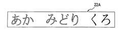
次に、この最終回の印字開始後のテープ移送量が、印字・切断間距離Dcpから、前余白量Lに空送り量を加算した送り量を減算した値よりも小さいとき、つまり切断位置(P位置)が前余白量Lの先頭位置に達していないときには(S120 :No)、S118 〜S120 が繰り返して実行される。そして、前余白量Lの先頭位置が切断位置に達したときには(S120 :Yes )、S107 以降が実行され、前余白量Lと後余白量Lとが夫々設けられてテープ切断され、この制御を終了して、同様にS10にリターンする。例えば、図29に示すように、入力したテキスト「あか みどり くろ」について、前後余白量Lを夫々設けて文字列「あか」が赤で、文字列「みどり」が緑で、文字列「くろ」が黒で夫々印字されたテープ状ラベル22Aが得られる。
【0101】
次に、多色印字制御の作用について説明する。
【0102】
テキストが入力された後、印字色の色数Nと色順序とを設定する印字色順序設定処理が実行され、更に複数色で印字する各印字色毎の印字対象範囲を設定する処理が実行される。そして、最初の印字色Cと同様のリボン色Rのリボンカセット30が装着された後、サーマルヘッド12やテープ駆動モータ44を駆動制御して印字処理される。そして、リボンカセット30を交換して各印字処理が終了する毎に、印字テープ巻き戻し処理が実行される。
【0103】
即ち、印字テープ22の巻き戻しに際して、カバー開閉検出スイッチ102からのカバー開閉信号VSに基づいて、ヘッドリリース機構70がリリース作動されるとともに、リボン検出スイッチ群103からのリボン検出信号RSとして、6つの検出スイッチ信号の全てが「H」レベル信号であり、リボンカセット30がテープカセット20から取り外されたときには、リボンカセット30を装着しないように促すメッセージがディスプレイ5に表示され、キーボード4からの任意のキーあるいは特定のキーの入力を待つ。
【0104】
そして、キーボード4からの任意のキーあるいは特定のキーの入力があると、テープ駆動モータ44が逆回転駆動されて、印字テープ22は、自動的に巻き戻しされた後、テープ検出センサ91からのテープ検出信号TSに基づいて、印字開始基準原点位置でその巻き戻しが停止される。
【0105】
このように、各印字処理の終了毎に、複数色印字の為に準備された複数のリボンカセット30のうちから択一的に装着されたリボンカセット30がテープカセット20から取り外されたのを検知してから、キーボード4からの任意のあるいは特定のキー入力があれば、リボン・テープ移送機構40によるテープの巻き戻し方向への移送と、その巻き戻しに連動して、リボンカセット30内のリボン巻き取りスプール34の巻き戻し駆動が実行されることから、その巻き戻しに連動してリボン巻き取りスプール34を巻き戻し駆動させない連動解除機構を何ら設けることなく、インクリボン32の巻き戻しを確実に防止できる。
【0106】
また、使用者が、リボンカセット30を取り外している最中に不用意に取消キーに触れ、印字処理が途中で中止され、印字途中の印字テープ22を無駄にすることが防止される。
【0107】
尚、印字テープ22の巻き戻し時に、テープ検出センサ91からのテープ検出信号TSに基づいて、テープ有りからテープ無しに切り換わることで、印字テープ22の先端を検出するように構成したり、近接スイッチやフォトインタラプタなどの各種センサでリボン検出スイッチ群103を構成する等、本発明の技術的思想の範囲内において、前記実施例に関し、既存の技術や当業者に自明の技術に基いて種々の変更を加えることもあり得る。尚、リボン色の異なる複数のリボンカセット30を順次取り替えて多色印字する種々のテープ状ラベル作成装置に本発明を適用し得ることは勿論である。
【0108】
【発明の効果】
以上説明したことから明かなように、請求項1記載のテープ状ラベル作成装置によれば、各印字処理の終了毎に、リボンカセットが取り外されたのを検知してから、入力手段からのキー入力によって、テープ移送機構によるテープの巻き戻し方向への移送が開始され、その巻き戻しに連動して、リボンカセット内のリボン巻き取りスプールの巻き戻し駆動が実行されることから、その巻き戻しに連動してリボン巻き取りスプールを巻き戻し駆動させない連動解除機構を何ら設けることなく、インクリボンの巻き戻しを確実に防止できる。
【0109】
また、使用者がリボンカセットを取り外す際に不用意に入力手段に触れ、キー入力を行っても、テープの巻き戻しが実行されるのみで、印字処理が中止されることがないので、印字途中のテープを無駄にすることが防止できる。
【0110】
また、請求項2〜請求項4記載のテープ状ラベル作成装置によっても、請求項1と同様の効果を奏することができる。
【0111】
また、請求項5記載のテープ状ラベル作成装置によれば、請求項1と同様の効果を奏するが、さらに、印字終了毎のテープの巻き戻しを自動化することができる。
【図面の簡単な説明】
【図1】テープ状ラベル作成装置の平面図である。
【図2】印字状態のサーマル印字機構の平面図である。
【図3】テープ巻き戻し状態の図2相当図である。
【図4】リボンカセットを装着したテープカセットの平面図である。
【図5】テープカセットの平面図である。
【図6】リボンカセット内部の平面図である。
【図7】リボンカセットとテープカセットの背面斜視図である。
【図8】リボンカセットの斜視図である。
【図9】サーマル印字機構の印字状態における駆動系の平面図である。
【図10】ギヤの噛合関係を示す図9の要部縦断正面図である。
【図11】サーマル印字機構のテープ巻き戻し状態における駆動系の平面図である。
【図12】カセットカバーを閉じたときの要部縦断側面図である。
【図13】カセットカバーを開放したときの図12相当図である。
【図14】テープ切断機構を示すサーマル印字機構の側面図である。
【図15】テープ切断許可状態におけるサーマル印字機構の駆動系の平面図である。
【図16】テープ状ラベル作成装置の制御系のブロック図である。
【図17】多色印字制御のルーチンの概略フローチャートである。
【図18】印字色順序設定処理制御のルーチンの概略フローチャートである。
【図19】色毎の印字対象範囲設定処理制御のルーチンの概略フローチャートである。
【図20】最終の印字色について残りの文字列設定処理制御のルーチンの概略フローチャートである。
【図21】印字開始処理制御のルーチンの概略フローチャートである。
【図22】設定色印字処理制御のルーチンの概略フローチャートである。
【図23】印字テープ巻き戻し処理制御のルーチンの概略フローチャートである。
【図24】印字開始位置合せ処理制御のルーチンの概略フローチャートである。
【図25】最終色印字処理・切断処理制御のルーチンの概略フローチャートである。
【図26】印字位置(P位置)とテープ切断位置(C位置)とテープ検出位置(S位置)との位置関係を説明する説明図である。
【図27】テキストメモリ内のデータ構成を説明する説明図である。
【図28】(a)は、テープ上の印字開始基準原点位置の説明図であり、(b)は、前余白量分テープ送りしたときの説明図であり、(c)は、更に空送り量分テープ送りしたときの説明図である。
【図29】赤と緑と黒とで3色印字されたテープ状ラベルの平面図である。
【図30】他の実施態様に係る印字テープ巻き戻し処理制御のルーチンの概略フローチャートである。
【符号の説明】
1 テープ状ラベル作成装置
4 キーボード
10 サーマル印字機構
22 印字テープ
30 リボンカセット
32 インクリボン
103 リボン検出スイッチ群
CD 制御装置[0001]
BACKGROUND OF THE INVENTION
The present invention relates to a tape-shaped label producing apparatus, and more particularly to an apparatus for preventing rewinding of an ink ribbon of a ribbon cassette when rewinding a printed tape in order to repeatedly print the same printing area.
[0002]
[Prior art]
Conventionally, the applicant of the present application, as described in Japanese Patent Laid-Open No. 5-84994, is a label suitable for printing a character or symbol character or mark on a printing tape as a printing medium and affixing it to a back cover of a file. A tape-shaped label producing apparatus suitable for producing the tape was proposed and put into practical use. This label producing apparatus includes a keyboard, a display, and a thermal printing type printing mechanism. Characters and marks are printed on a printing tape (for example,
[0003]
By the way, the printing tape can be transferred not only in the feeding direction but also in the rewinding direction. For example, after printing characters and symbols on the printing tape as the first time, the printing tape is wound up to the first printing start position. It is conceivable that a tape-like label on which a composite character or a design pattern is printed is created by returning and executing the second printing by overlapping characters and symbols.
[0004]
In addition, the tape-like label created by character printing is not limited to the back cover of a file, but is suitable for application to, for example, a cassette tape or a cassette tape case thereof, or a video tape or a video tape case thereof. By repeating the printing process and the rewinding of the printing tape, it is conceivable to create a tape-like label in which a print character string is printed in a multicolored manner according to the recorded contents and genre.
[0005]
Therefore, the inventors of the present application are not only “black” but also a plurality of types of ribbon cassettes, such as “red”, “green”, “blue”,... The ribbon cassette is configured to be detachable from the tape cassette, and the color for multicolor printing is set in the order of printing, while the input text is Execute the color range setting process to set the print target range for each print color to be printed with the set multiple colors, and print the ribbon cassette having the same ribbon color as the set print color in order At the same time, by rewinding the printing tape to the printing start position for each printing process, you can create a label that prints composite characters and design patterns, and colorfully prints in multiple colors I was inspired to create the label.
[0006]
[Problems to be solved by the invention]
Here, the ribbon cassette is provided with a ribbon spool in which an ink ribbon is wound and a ribbon take-up spool for taking up the ink ribbon. Generally, only the ribbon take-up spool is interlocked with the feeding operation of the print tape. Is driven to take up the printed ink ribbon.
[0007]
As invented by the inventors of the present application, in order to create a label printed with composite characters or a design pattern, or a label printed with multiple colors in a multicolored manner, a single ribbon cassette or a ribbon color When different ribbon cassettes are sequentially replaced to perform printing processing, and when the printing tape is rewound to the printing start position for each printing process, the ribbon in the ribbon cassette is linked with the rewinding when the printing tape is rewound. When the take-up spool is driven to rewind in the opposite direction, the ink ribbon wound on the ribbon take-up spool is fed out in a large amount and entangled in the ribbon cassette. A separate interlock release mechanism will be provided to prevent the ribbon take-up spool from being driven in conjunction with rewinding. Mar printing mechanism there is a problem that complicated and large in size.
[0008]
Also, if the user inadvertently operates the keyboard cancel key when replacing the ribbon cassette, printing will be interrupted even during multicolor printing, and the printed tape will be wasted. There is a problem of becoming.
[0009]
The present invention has been made in order to solve the above-described problems. When the tape is rewound by the tape transfer mechanism, the ribbon take-up spool in the ribbon cassette is not driven to rewind when the tape is rewound. To provide a tape-shaped label producing apparatus that can prevent rewinding of an ink ribbon without providing any release mechanism, and that does not interrupt printing by a key input operation of an inadvertent input means during ribbon cassette replacement. is there.
[0010]
[Means for Solving the Problems]
In order to achieve this object, the tape-shaped label producing apparatus according to
[0011]
In the tape-shaped label producing apparatus according to
[0012]
The tape-shaped label producing apparatus according to
[0013]
The tape-shaped label producing apparatus according to the second aspect configured as described above operates in substantially the same manner as the first aspect. That is, at the end of each printing process, when it is detected that a ribbon cassette that is alternatively mounted from a plurality of ribbon cassettes prepared for multi-color printing is removed, the input means When a key is input from, the tape rewinding control means executes the tape transfer in the tape rewind direction by the tape transfer mechanism.
[0014]
The tape-shaped label producing apparatus according to
[0015]
Further, the tape-shaped label producing apparatus according to
[0016]
The tape-shaped label producing apparatus according to
[0017]
DETAILED DESCRIPTION OF THE INVENTION
Hereinafter, embodiments of the present invention will be described with reference to the drawings.
[0018]
In this embodiment, the present invention is applied to a tape-shaped label producing apparatus capable of multicolor printing by replacing a plurality of ribbon cassettes having different ribbon colors with a printing tape as a printing medium for a large number of characters such as characters and symbols. Is the case.
[0019]
As shown in FIG. 1, a
[0020]
Next, the
[0021]
First, the
[0022]
Inside the
[0023]
Further, as shown in FIG. 7, two spaced apart portions of the outer peripheral wall of the
[0024]
Next, the
[0025]
In the
[0026]
Further, a
[0027]
On the other hand, a ribbon
[0028]
At this time, the pair of engaging
[0029]
At this time, the
[0030]
By the way, the
[0031]
Next, a tape /
[0032]
The
[0033]
Further, a
[0034]
On the other hand, the base end portion of the
[0035]
As shown in FIG. 9, when the
[0036]
Incidentally, a
[0037]
Here, the
[0038]
At this time, the
[0039]
Here, when the
[0040]
Next, a
[0041]
As shown in FIGS. 12 to 13, the rear end of the
[0042]
Then, when the
[0043]
Further, when the
[0044]
As shown in FIGS. 2 and 9, when printing is performed, the
[0045]
In this state, when the
[0046]
At the same time, the
[0047]
On the other hand, when the first color printing is completed and the second color printing is executed, the
[0048]
Next, a
[0049]
The lower end portion of the fixed
[0050]
However, when the
[0051]
Next, a
[0052]
[0053]
Then, the sensor light emitted from the
[0054]
Next, the control system of the tape-shaped
[0055]
The input /
[0056]
The control device CD includes a
[0057]
The
[0058]
The
[0059]
In the
[0060]
Next, a routine for multicolor printing control performed by the control device CD of the tape-shaped
[0061]
Here, prior to the multicolor printing control, the positional relationship among the tape detection position by the
[0062]
When the tape
[0063]
Next, print color order setting process control (see FIG. 18) is executed (S12).
[0064]
When this control is started, the message “What is the number of print colors?” Is displayed on the
[0065]
Next, in multicolor printing control, printing target range setting processing control (see FIG. 19) for each color is executed (S13).
[0066]
When this control is started, first, the color number N is set to the count value I of the color number counter (S33), and when "1" is subtracted from this color number count value I and is not "0", that is, the final value When the print character string is not set (S34: No), the character or symbol to be printed is selected with the cursor for the first print color in the print color order among the unset colors based on the color order data. A print target character string setting process instructed and set is executed (S35).
[0067]
That is, in this print target character string setting process, text data is displayed on the
[0068]
Then, the color number count value I is decremented by 1 (S36), and S34 to S36 are repeatedly executed until (I-1) becomes "0". When (I-1) becomes “0” and the setting of the print target character string is completed for each print color other than the final print color (S34: Yes), the text data for the final print color is displayed. Among these, a character string setting process for setting the remaining characters excluding the already set characters and symbols is executed (S37).
[0069]
This character string setting process will be specifically described with reference to FIG. 20. First, character data stored in the
[0070]
For example, if the character data “Akamidori Kuro” is stored in the
[0071]
Here, when the setting of the print color “green” is completed, the color count value (I−1) becomes “0”. Therefore, in the character string setting process of S37, the character data is read sequentially from the top of the
[0072]
Next, the message “What is the margin amount of the print tape?” Is displayed on the
[0073]
In the multicolor printing control, when the printing key is operated (S14 / S15: Yes), the printing start process control (see FIG. 21) is executed (S16).
[0074]
When this control is started, the ribbon color R of the loaded
[0075]
Next, based on the cover open / close signal VS of the cover open /
[0076]
Next, the
[0077]
Then, when the tape detection signal TS becomes “L” level and enters the leading
[0078]
Next, in multicolor printing control, when the number of colors N is not “1”, that is, when printing is not the last time (S17: No), set color printing processing control for printing with each set printing color (see FIG. 22). Is executed (S18).
[0079]
When this control is started, as shown in FIG. 28B, first, the
[0080]
Next, in multicolor printing control, printing tape rewinding processing control (see FIG. 23) is executed (S19).
[0081]
When this control is started, the
[0082]
Next, a message prompting the user to remove the
[0083]
If any key on the
[0084]
As described above, when it is detected that the
[0085]
The printing tape rewinding process control can be changed as shown in FIG.
[0086]
In the printing tape rewinding process control shown in FIG. 30, the steps S170 to S173 are the same as the steps S70 to S73 of the printing tape rewinding process control shown in FIG. In the processing control shown in FIG. 30, when the
[0087]
Note that the steps S176 to S179 shown in FIG. 30 correspond to the steps S75 to S78 shown in FIG.
[0088]
As described above, in the printing tape rewinding process control shown in FIG. 30, when it is detected that the
[0089]
When this control is started, an error message for prompting the user to mount the
[0090]
Next, when the ribbon color R and the next print color C match (S84: Yes), a character string storing the data of the next print color C is read from the
[0091]
Next, in multicolor printing control, the number of colors N is decremented by 1 (S21), and when the number of colors N is not "1" and printing is not the last time (S17: No), S18 to S21 are repeatedly executed. The When the number of colors N is “1” and printing is performed for the last time (S17: Yes), final color printing process / cutting process control (see FIG. 25) is executed (S22).
[0092]
In this control, the first case where the front margin amount L is larger than the printing / cutting distance Dcp and the second case where there is no blank feed amount when the front margin amount L is smaller than the printing / cutting distance Dcp. In the third case where there is a blank feed amount and the value obtained by adding the front margin amount L to the blank feed amount is a third case where the distance between printing and cutting Dcp is greater than or equal to the fourth case where the distance between printing and cutting is smaller than Dcp. In this case, the tape is cut while printing.
[0093]
First, the first case will be described. When the front margin amount L is equal to or greater than the printing / cutting distance Dcp (S90: Yes), the
[0094]
Next, when the printing start position of printing by the final printing color this time is upstream of the printing start reference origin position of label printing in the feeding direction T and there is an idle feed amount (S96: Yes), the
[0095]
Next, the second case will be described. When the front margin amount L is smaller than the printing / cutting distance Dcp and there is no idle feed amount (S90 / S102: No), the
[0096]
That is, dot pattern data for one dot row is read from the
[0097]
When the leading position of the front margin L has reached the cutting position (S106: Yes), printing and tape transfer are stopped (S107), and then the
[0098]
Next, when the front margin amount L is smaller than the printing / cutting distance Dcp, a value obtained by adding the front margin amount L to the blank feeding amount and the blanking amount is equal to or larger than the printing / cutting distance Dcp. In the case of (S90: No, S102, S111: Yes), the tape is cut after the tape transfer (S112 to S115) in the same manner as S91 to S94 (S112 to S115). The
[0099]
On the other hand, when the front margin amount L is smaller than the printing / cutting distance Dcp, there is a fourth value in which there is a blank feed amount and the value obtained by adding the front margin amount L to the blank feeding amount is smaller than the printing / cutting distance Dcp. Sometimes (S90: No, S102: Yes, S111: No), the
[0100]
Next, when the tape transfer amount after the start of the final printing is smaller than the value obtained by subtracting the feed amount obtained by adding the idle feed amount to the front margin amount L from the printing / cutting distance Dcp, that is, the cutting position ( When (P position) does not reach the leading position of the front margin amount L (S120: No), S118 to S120 are repeatedly executed. When the leading position of the front margin amount L reaches the cutting position (S120: Yes), S107 and subsequent steps are executed, the front margin amount L and the rear margin amount L are provided, respectively, and the tape is cut. The process ends, and the process returns to S10 in the same manner. For example, as shown in FIG. 29, for the input text “Akamidori Kuro”, the front and rear margins L are provided, the character string “Aka” is red, the character string “Midori” is green, and the character string “Kuro” The tape-
[0101]
Next, the operation of multicolor printing control will be described.
[0102]
After the text is input, a print color order setting process for setting the number N of print colors and the color order is executed, and further, a process for setting a print target range for each print color to be printed with a plurality of colors is executed. The Then, after the
[0103]
That is, when the
[0104]
When an arbitrary key or a specific key is input from the
[0105]
In this way, at the end of each printing process, it is detected that the
[0106]
Further, it is possible to prevent the user from touching the cancel key carelessly while removing the
[0107]
Note that when the
[0108]
【The invention's effect】
As is apparent from the above description, according to the tape-shaped label producing apparatus of the first aspect, the key from the input means is detected after detecting the removal of the ribbon cassette at the end of each printing process. By the input, the tape transport mechanism starts transporting the tape in the rewinding direction, and the rewinding drive of the ribbon take-up spool in the ribbon cassette is executed in conjunction with the rewinding. Ink ribbon rewinding can be reliably prevented without providing any interlock release mechanism that does not drive the ribbon take-up spool to rewind.
[0109]
Also, even if the user carelessly touches the input means when removing the ribbon cassette and performs key input, the tape is only rewound and the printing process is not interrupted. It is possible to prevent the tape from being wasted.
[0110]
Also, the tape-like label producing apparatus according to any one of
[0111]
Moreover, according to the tape-shaped label production apparatus of
[Brief description of the drawings]
FIG. 1 is a plan view of a tape-shaped label producing apparatus.
FIG. 2 is a plan view of a thermal printing mechanism in a printing state.
FIG. 3 is a view corresponding to FIG. 2 in a tape rewind state.
FIG. 4 is a plan view of a tape cassette with a ribbon cassette mounted thereon.
FIG. 5 is a plan view of the tape cassette.
FIG. 6 is a plan view of the inside of the ribbon cassette.
FIG. 7 is a rear perspective view of a ribbon cassette and a tape cassette.
FIG. 8 is a perspective view of a ribbon cassette.
FIG. 9 is a plan view of a drive system in a printing state of a thermal printing mechanism.
10 is a longitudinal sectional front view of the main part of FIG. 9 showing the meshing relationship of gears.
FIG. 11 is a plan view of the drive system in the tape rewind state of the thermal printing mechanism.
FIG. 12 is a longitudinal sectional side view of the main part when the cassette cover is closed.
FIG. 13 is a view corresponding to FIG. 12 when the cassette cover is opened.
FIG. 14 is a side view of a thermal printing mechanism showing a tape cutting mechanism.
FIG. 15 is a plan view of a drive system of the thermal printing mechanism in a tape cutting permission state.
FIG. 16 is a block diagram of a control system of the tape-shaped label producing apparatus.
FIG. 17 is a schematic flowchart of a routine for multicolor printing control.
FIG. 18 is a schematic flowchart of a routine of print color order setting process control.
FIG. 19 is a schematic flowchart of a routine for controlling a print target range setting process for each color.
FIG. 20 is a schematic flowchart of a remaining character string setting process control routine for the final print color.
FIG. 21 is a schematic flowchart of a routine for controlling printing start processing.
FIG. 22 is a schematic flowchart of a set color printing process control routine;
FIG. 23 is a schematic flowchart of a printing tape rewinding process control routine;
FIG. 24 is a schematic flowchart of a routine for print start alignment processing control.
FIG. 25 is a schematic flowchart of a final color printing process / cutting process control routine;
FIG. 26 is an explanatory diagram illustrating a positional relationship among a printing position (P position), a tape cutting position (C position), and a tape detection position (S position).
FIG. 27 is an explanatory diagram illustrating a data configuration in a text memory.
FIG. 28A is an explanatory diagram of a print start reference origin position on the tape, FIG. 28B is an explanatory diagram when the tape is fed by the amount of the front margin, and FIG. It is explanatory drawing when the amount of tapes is fed.
FIG. 29 is a plan view of a tape-like label printed in three colors of red, green and black.
FIG. 30 is a schematic flowchart of a printing tape rewinding process control routine according to another embodiment.
[Explanation of symbols]
1 Tape label making device
4 Keyboard
10 Thermal printing mechanism
22 Printing tape
30 Ribbon cassette
32 Ink ribbon
103 Ribbon detection switch group
CD controller
Claims (5)
Translated fromJapanese前記カセット検出手段がリボンカセットが外されたことを検知しているときに、前記入力手段からキー入力されると、テープ移送機構によるテープの印字開始位置までテープの巻き戻しを自動的に実行させるテープ巻き戻し制御手段を備えたことを特徴とするテープ状ラベル作成装置。Input means for inputting characters, symbols, and various commands, data storage means for storing input text data, display means including a display, and a tape as a printing medium in a feeding direction and a rewinding direction A tape transfer mechanism that selectively transfers, a ribbon cassette that contains an ink ribbon and is detachably mounted, cassette detection means for detecting whether or not the ribbon cassette is mounted, and a print including a print head for printing on the tape In the tape-shaped label producing apparatus comprising the means and the control means for controlling the printing,
When the cassette detecting means detects that the ribbon cassette has been removed, if a key is input from the input means, the tape is automatically rewound to the tape printing start position by the tape transport mechanism. A tape-shaped label producing apparatus comprising a tape rewinding control means.
前記カセット検出手段がリボンカセットが外されたことを検知しているときに、前記入力手段からキー入力されると、テープ移送機構によるテープの印字開始位置までテープの巻き戻しを自動的に実行させるテープ巻き戻し制御手段を備えたことを特徴とするテープ状ラベル作成装置。Input means for inputting characters, symbols, and various commands, data storage means for storing input text data, display means including a display, and a tape as a printing medium in a feeding direction and a rewinding direction A plurality of ribbon cassettes that are accommodated in a plurality of colors, and that can be detachably mounted to sequentially print in a plurality of colors, and a ribbon cassette. In a tape-shaped label producing apparatus comprising a cassette detection means for detecting the presence or absence of mounting, a printing means including a print head for printing on a tape, and a control means for controlling printing.
When the cassette detecting means detects that the ribbon cassette has been removed, if a key is input from the input means, the tape is automatically rewound to the tape printing start position by the tape transport mechanism. A tape-shaped label producing apparatus comprising a tape rewinding control means.
Priority Applications (3)
| Application Number | Priority Date | Filing Date | Title |
|---|---|---|---|
| JP01508296AJP3644111B2 (en) | 1996-01-31 | 1996-01-31 | Tape label production equipment |
| US08/790,458US6132120A (en) | 1995-03-29 | 1997-01-29 | Tape-shaped label printing device |
| EP97101461AEP0787591A1 (en) | 1996-01-31 | 1997-01-30 | Tape-shaped label printing device |
Applications Claiming Priority (1)
| Application Number | Priority Date | Filing Date | Title |
|---|---|---|---|
| JP01508296AJP3644111B2 (en) | 1996-01-31 | 1996-01-31 | Tape label production equipment |
Publications (2)
| Publication Number | Publication Date |
|---|---|
| JPH09207403A JPH09207403A (en) | 1997-08-12 |
| JP3644111B2true JP3644111B2 (en) | 2005-04-27 |
Family
ID=11878930
Family Applications (1)
| Application Number | Title | Priority Date | Filing Date |
|---|---|---|---|
| JP01508296AExpired - LifetimeJP3644111B2 (en) | 1995-03-29 | 1996-01-31 | Tape label production equipment |
Country Status (2)
| Country | Link |
|---|---|
| EP (1) | EP0787591A1 (en) |
| JP (1) | JP3644111B2 (en) |
Families Citing this family (1)
| Publication number | Priority date | Publication date | Assignee | Title |
|---|---|---|---|---|
| JP7354619B2 (en)* | 2019-06-28 | 2023-10-03 | ブラザー工業株式会社 | editing device |
Family Cites Families (6)
| Publication number | Priority date | Publication date | Assignee | Title |
|---|---|---|---|---|
| JPH0584994A (en) | 1991-09-26 | 1993-04-06 | Brother Ind Ltd | Tape printer |
| JP2839779B2 (en)* | 1992-02-27 | 1998-12-16 | シャープ株式会社 | Printing control device |
| EP0573187B1 (en)* | 1992-06-01 | 1997-12-17 | Esselte N.V. | Thermal printing device |
| GB9300586D0 (en)* | 1993-01-13 | 1993-03-03 | Esselte Dymo Nv | Tape printing apparatus |
| JPH06328821A (en)* | 1993-05-19 | 1994-11-29 | Brother Ind Ltd | Tape cassette |
| JPH0768814A (en)* | 1993-09-06 | 1995-03-14 | Brother Ind Ltd | Tape printer |
- 1996
- 1996-01-31JPJP01508296Apatent/JP3644111B2/ennot_activeExpired - Lifetime
- 1997
- 1997-01-30EPEP97101461Apatent/EP0787591A1/ennot_activeCeased
Also Published As
| Publication number | Publication date |
|---|---|
| EP0787591A1 (en) | 1997-08-06 |
| JPH09207403A (en) | 1997-08-12 |
Similar Documents
| Publication | Publication Date | Title |
|---|---|---|
| JP3111445B2 (en) | Tape-shaped label making device | |
| US6132120A (en) | Tape-shaped label printing device | |
| JP2006240310A (en) | Tape-like label making apparatus and tape cassette | |
| JP2976843B2 (en) | Tape-shaped label making device | |
| JP3045054B2 (en) | Tape-shaped label making device | |
| JP3674132B2 (en) | Tape label production equipment | |
| JP3003793B2 (en) | Tape-shaped label making device | |
| JP3644111B2 (en) | Tape label production equipment | |
| JP4016997B2 (en) | Tape cassette | |
| JP2006289988A (en) | Tape cassette | |
| JP3787881B2 (en) | Tape label production equipment | |
| JP3671500B2 (en) | Tape label production equipment | |
| JP4096078B2 (en) | Tape label production equipment | |
| JP3757447B2 (en) | Tape label production equipment | |
| JP3003794B2 (en) | Tape-shaped label making device | |
| JPH10217563A (en) | Tape-shaped label making device | |
| JP2965128B2 (en) | Tape-shaped label making device | |
| JP3539007B2 (en) | Tape-shaped label making device | |
| JP3028103B2 (en) | Tape-shaped label making device | |
| JPH08267884A (en) | Tape label making device | |
| JP2006103337A (en) | Tape label production equipment | |
| JP2979538B2 (en) | Tape-shaped label making device | |
| JPH09109474A (en) | Tape-shaped label making device | |
| JPH08300753A (en) | Tape label making device | |
| JPH09202025A (en) | Tape-shaped label making device |
Legal Events
| Date | Code | Title | Description |
|---|---|---|---|
| A977 | Report on retrieval | Free format text:JAPANESE INTERMEDIATE CODE: A971007 Effective date:20041222 | |
| TRDD | Decision of grant or rejection written | ||
| A01 | Written decision to grant a patent or to grant a registration (utility model) | Free format text:JAPANESE INTERMEDIATE CODE: A01 Effective date:20050111 | |
| A61 | First payment of annual fees (during grant procedure) | Free format text:JAPANESE INTERMEDIATE CODE: A61 Effective date:20050124 | |
| R150 | Certificate of patent or registration of utility model | Free format text:JAPANESE INTERMEDIATE CODE: R150 | |
| FPAY | Renewal fee payment (event date is renewal date of database) | Free format text:PAYMENT UNTIL: 20080210 Year of fee payment:3 | |
| FPAY | Renewal fee payment (event date is renewal date of database) | Free format text:PAYMENT UNTIL: 20090210 Year of fee payment:4 | |
| FPAY | Renewal fee payment (event date is renewal date of database) | Free format text:PAYMENT UNTIL: 20090210 Year of fee payment:4 | |
| FPAY | Renewal fee payment (event date is renewal date of database) | Free format text:PAYMENT UNTIL: 20100210 Year of fee payment:5 | |
| FPAY | Renewal fee payment (event date is renewal date of database) | Free format text:PAYMENT UNTIL: 20100210 Year of fee payment:5 | |
| FPAY | Renewal fee payment (event date is renewal date of database) | Free format text:PAYMENT UNTIL: 20110210 Year of fee payment:6 | |
| FPAY | Renewal fee payment (event date is renewal date of database) | Free format text:PAYMENT UNTIL: 20120210 Year of fee payment:7 | |
| FPAY | Renewal fee payment (event date is renewal date of database) | Free format text:PAYMENT UNTIL: 20120210 Year of fee payment:7 | |
| FPAY | Renewal fee payment (event date is renewal date of database) | Free format text:PAYMENT UNTIL: 20130210 Year of fee payment:8 | |
| FPAY | Renewal fee payment (event date is renewal date of database) | Free format text:PAYMENT UNTIL: 20140210 Year of fee payment:9 | |
| EXPY | Cancellation because of completion of term |