JP3641258B2 - Electronics - Google Patents
ElectronicsDownload PDFInfo
- Publication number
- JP3641258B2 JP3641258B2JP2002245372AJP2002245372AJP3641258B2JP 3641258 B2JP3641258 B2JP 3641258B2JP 2002245372 AJP2002245372 AJP 2002245372AJP 2002245372 AJP2002245372 AJP 2002245372AJP 3641258 B2JP3641258 B2JP 3641258B2
- Authority
- JP
- Japan
- Prior art keywords
- refrigerant
- cpu
- coolant
- leaking
- heat
- Prior art date
- Legal status (The legal status is an assumption and is not a legal conclusion. Google has not performed a legal analysis and makes no representation as to the accuracy of the status listed.)
- Expired - Fee Related
Links
Images


Classifications
- G—PHYSICS
- G06—COMPUTING OR CALCULATING; COUNTING
- G06F—ELECTRIC DIGITAL DATA PROCESSING
- G06F1/00—Details not covered by groups G06F3/00 - G06F13/00 and G06F21/00
- G06F1/16—Constructional details or arrangements
- G06F1/20—Cooling means
- G06F1/203—Cooling means for portable computers, e.g. for laptops
- G—PHYSICS
- G06—COMPUTING OR CALCULATING; COUNTING
- G06F—ELECTRIC DIGITAL DATA PROCESSING
- G06F1/00—Details not covered by groups G06F3/00 - G06F13/00 and G06F21/00
- G06F1/16—Constructional details or arrangements
- G06F1/20—Cooling means
- G06F1/206—Cooling means comprising thermal management
- H—ELECTRICITY
- H01—ELECTRIC ELEMENTS
- H01L—SEMICONDUCTOR DEVICES NOT COVERED BY CLASS H10
- H01L23/00—Details of semiconductor or other solid state devices
- H01L23/34—Arrangements for cooling, heating, ventilating or temperature compensation ; Temperature sensing arrangements
- H01L23/46—Arrangements for cooling, heating, ventilating or temperature compensation ; Temperature sensing arrangements involving the transfer of heat by flowing fluids
- H01L23/473—Arrangements for cooling, heating, ventilating or temperature compensation ; Temperature sensing arrangements involving the transfer of heat by flowing fluids by flowing liquids
- G—PHYSICS
- G06—COMPUTING OR CALCULATING; COUNTING
- G06F—ELECTRIC DIGITAL DATA PROCESSING
- G06F2200/00—Indexing scheme relating to G06F1/04 - G06F1/32
- G06F2200/20—Indexing scheme relating to G06F1/20
- G06F2200/201—Cooling arrangements using cooling fluid
- G—PHYSICS
- G06—COMPUTING OR CALCULATING; COUNTING
- G06F—ELECTRIC DIGITAL DATA PROCESSING
- G06F2200/00—Indexing scheme relating to G06F1/04 - G06F1/32
- G06F2200/20—Indexing scheme relating to G06F1/20
- G06F2200/203—Heat conductive hinge
- H—ELECTRICITY
- H01—ELECTRIC ELEMENTS
- H01L—SEMICONDUCTOR DEVICES NOT COVERED BY CLASS H10
- H01L2924/00—Indexing scheme for arrangements or methods for connecting or disconnecting semiconductor or solid-state bodies as covered by H01L24/00
- H01L2924/0001—Technical content checked by a classifier
- H01L2924/0002—Not covered by any one of groups H01L24/00, H01L24/00 and H01L2224/00
Landscapes
- Engineering & Computer Science (AREA)
- Theoretical Computer Science (AREA)
- Physics & Mathematics (AREA)
- General Physics & Mathematics (AREA)
- Computer Hardware Design (AREA)
- Human Computer Interaction (AREA)
- General Engineering & Computer Science (AREA)
- Condensed Matter Physics & Semiconductors (AREA)
- Microelectronics & Electronic Packaging (AREA)
- Power Engineering (AREA)
- Cooling Or The Like Of Electrical Apparatus (AREA)
- Cooling Or The Like Of Semiconductors Or Solid State Devices (AREA)
Description
Translated fromJapanese【0001】
【発明の属する技術分野】
本発明は、例えばCPUのような発熱体を液状の冷媒を用いて冷却する液冷式の電子機器に係り、特に冷媒流路の接続部分からの冷媒の漏れを防止する構造に関する。
【0002】
【従来の技術】
例えばノート形のポータブルコンピュータに用いられるCPUは、処理速度の高速化や多機能化に伴い動作中の発熱量が増加している。このため、近年、空気よりも遥かに高い比熱を有する液状の冷媒を用いてCPUを冷却する、いわゆる液冷式の冷却システムが開発されている。
【0003】
「特開平7−142886号公報」は、ポータブルコンピュータに用いる液冷式の冷却システムの一例を開示している。この冷却システムは、受熱ヘッダ、放熱ヘッダおよび冷媒を循環させるチューブを備えている。受熱ヘッダは、ポータブルコンピュータの筐体に収容されて、CPUに熱的に接続されている。放熱ヘッダは、ポータブルコンピュータの表示装置に収容されている。チューブは、筐体と表示装置とに跨って配管され、受熱ヘッダと放熱ヘッダとの間を接続している。
【0004】
この冷却システムによると、CPUの熱は、受熱ヘッダでの熱交換により冷媒に伝えられる。この受熱ヘッダで加熱された冷媒は、チューブを通じて放熱ヘッダに移送され、この放熱ヘッダを通過する過程でCPUの熱を放出する。この放熱ヘッダでの熱交換により冷やされた冷媒は、チューブを通じて受熱ヘッダに戻され、再びCPUの熱を受ける。この冷媒の循環により、CPUの熱を効率良く放熱ヘッダに移送することができ、CPUの冷却性能が高まる。
【0005】
ところで、液冷式の冷却システムでは、液状の冷媒を受熱ヘッダと放熱ヘッダとの間で循環させているので、この冷媒の循環経路から若干の冷媒が漏れる可能性があり得る。この冷媒の漏れが発生し易い箇所としては、例えば受熱ヘッダのような部品とチューブとの接続部分が掲げられる。従来の冷却システムでは、受熱ヘッダの冷媒入口および冷媒出口に管継手を設置し、この管継手にチューブの端部を差し込むことで、受熱ヘッダとチューブとを接続している。さらに、接続をより強固なものとするため、チューブと管継手の接続部分を外側からバンドで締め付けることで、管継手からのチューブの脱落を阻止している。
【0006】
【発明が解決しようとする課題】
液冷式の冷却システムでは、冷媒の循環経路に若干の漏れがあったり、循環経路に若干の気泡が混入したとしても、冷媒の循環に特別の支障がない限りCPUの冷却性能が極端に悪化することはない。
【0007】
しかしながら、冷媒が一定量以上漏れると、この漏れた冷媒が筐体内のCPUや各種の電子部品に付着するのを避けられない。特に不凍液を含む冷媒は、導電性を有するためにCPUや電子部品に致命的なダメージを与えることになり、ポータブルコンピュータが動作不能に陥ることがある。さらに、漏れた冷媒が筐体の外部に流出すると、例えば衣類や机の上を汚すことにもなり、ポータブルコンピュータの使用環境に悪影響を及ぼす。
【0008】
また、従来のチューブと受熱ヘッドとの接続構造によると、長期間に亘る使用によりチューブが管継手の形状に馴染んだり、バンドが弛む等してチューブが管継手を締め付ける力が失われることがあり得る。このような状態に陥ると、チューブと管継手の接続部分からの冷媒の漏洩を止めることができなくなり、漏れた冷媒が筐体の内部に流れ出すといった問題がある。
【0009】
一方、例えば「特開平4−258591号公報」は、配管の接続部分からの液体の漏洩を防止するための構成を開示している。この先行技術では、一方の配管の接続端に管状のパッキン部材を取り付けるとともに、他方の配管の接続端に管状の押嵌部材を取り付けている。パッキン部材および押嵌部材は、高吸水ポリマーを配合したゴム材料により形成されている。
【0010】
この先行技術によると、パッキン部材と押嵌部材とは、一方の配管の接続端と他方の配管の接続端との間において、互いに噛み合った状態で圧接し、これら配管の接続端の間を液密にシールしている。
【0011】
しかしながら、上記先行技術では、パッキン部材の内側に押嵌部材が嵌め込まれるため、この嵌め込み時にパッキン部材や押嵌部材がずれないように配管の接続端に固定する格別なストッパを必要とするとともに、パッキン部材と押嵌部材とを互いに噛み合わせるための複数の係合部を必要とする。
【0012】
この結果、パッキン部材および押嵌部材の形状が複雑化するのを避けられず、個々の単価が高くなるといったコスト的な問題が生じてくる。加えて、上記先行技術は、専ら高層集合住宅の圧力配管の接続構造を開示しているに止まり、電子部品を内蔵したポータブルコンピュータのような電子機器とでは分野が異なるとともに、この電子機器用の冷却システムへの適用については、何等言及されていない。
【0013】
本発明の目的は、冷媒流路からの冷媒の漏れを防止できるとともに、たとえ冷媒に漏れが生じたとしても、漏れた冷媒によってCPUのような発熱体が致命的なダメージを受けずに済む電子機器を得ることにある。
【0014】
【課題を解決するための手段】
上記目的を達成するため、本発明に係る電子機器は、
発熱体を収容する筐体と、
第1の管路と、この第1の管路に接続された第2の管路とを有し、上記発熱体を冷却する液状の冷媒が流れる冷媒流路と、
上記第1の管路と上記第2の管路との接続部分を覆う吸水性を有するパッキン材と、
上記パッキン材が上記冷媒を吸っているか否かを検知する検知手段と、
上記検知手段によって上記冷媒の存在が検知された時に、上記第1の管路と上記第2の管路との接続部分から冷媒が漏れていると判断し、機器の動作を停止させる制御手段と、を具備したことを特徴としている。
この構成によれば、第1の管路と第2の管路の接続部分から冷媒が漏れた場合、パッキン材が冷媒を吸収する。この吸収によりパッキン材の体積が増加し、管路の接続部分を外側から圧迫する。よって、管路の接続部分からの冷媒の漏れを防止することができる。
それとともに、管路の接続部分から冷媒が漏れると、電子機器の動作が停止するので、漏れた冷媒によりCPUのような発熱体が致命的なダメージを受けずに済む。
【0015】
【発明の実施の形態】
以下本発明の第1の実施の形態を図1ないし図7にもとづいて説明する。
【0016】
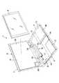
図1ないし図3は、電子機器としてのポータブルコンピュータ1を開示している。ポータブルコンピュータ1は、コンピュータ本体2とディスプレイユニット3とで構成されている。コンピュータ本体2は、偏平な箱形の筐体4を備えている。筐体4は、底壁4a、上壁4b、前壁4c、左右の側壁4dおよび後壁4eを有している。上壁4bは、キーボード5を支持している。
【0017】
ディスプレイユニット3は、液晶表示パネル6と、この液晶表示パネル6を収容するディスプレイハウジング7とを備えている。ディスプレイハウジング7は、筐体4の後端部に図示しないヒンジを介して支持されている。
【0018】
そのため、ディスプレイユニット3は、キーボード5を上方から覆うように倒される閉じ位置と、キーボード5を露出させるように起立する開き位置とに亘って回動可能となっている。
【0019】
図1および図3に示すように、筐体4は、プリント配線板9、ハードディスク駆動装置10およびCD−ROM駆動装置11を収容している。プリント配線板9、ハードディスク駆動装置10およびCD−ROM駆動装置11は、筐体4の底壁4aの上に並べて配置されている。
【0020】
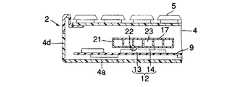
図4に示すように、プリント配線板9の上面に発熱体としてのCPU12が実装されている。CPU12は、例えばBGA形の半導体パッケージにて構成され、プリント配線板9の後部に位置している。CPU12は、四角いベース基板13と、このベース基板13の中央部に配置されたICチップ14とを有している。ICチップ14は、CPU12の処理速度の高速化や多機能化に伴って動作中の発熱量が非常に大きく、安定した動作を維持するために冷却を必要としている。
【0021】
ポータブルコンピュータ1は、CPU12を冷却する液例式の冷却ユニット16を搭載している。冷却ユニット16は、受熱部17、放熱部としての放熱器18、冷媒流路19およびポンプ20を備えている。
【0022】
図4および図5に示すように、受熱部17は、金属製のハウジング21を有している。ハウジング21は、偏平な箱形であり、上記筐体4に収容されたプリント配線板9の上面に固定されている。ハウジング21は、CPU12よりも一回り大きな平面形状を有し、このハウジング21の下面は、平坦な受熱面22となっている。この受熱面22は、図示しない熱伝導性グリース又は熱伝導性シートを介してCPU12のICチップ14に熱的に接続されている。
【0023】
さらに、ハウジング21の内部に冷媒通路23が形成されている。冷媒通路23は、受熱面22を介してICチップ14に熱的に接続されている。ハウジング21は、冷媒入口24および冷媒出口25を有している。冷媒入口24は、冷媒通路23の上流端に位置し、冷媒出口25は、冷媒通路23の下流端に位置している。
【0024】
放熱器18は、ディスプレイハウジング7の背面と液晶表示パネル6との間に介在されている。放熱器18は、液晶表示パネル6と略同等の大きさを有する長方形の板状をなしている。図6に示すように、放熱器18は、第1の放熱板27と第2の放熱板28とを備えている。これら放熱板27,28は、夫々金属製であり、互いに重ね合わされている。
【0025】
第1の放熱板27は、第2の放熱板28の反対側に張り出す膨出部29を有している。膨出部29は、第1の放熱板27の略全面に亘って蛇行状に形成されている。この膨出部29の開口端は、第2の放熱板28によって閉じられている。そのため、第1の放熱板27の膨出部29は、第2の放熱板28との間に冷媒通路30を構成している。
【0026】
放熱器18は、冷媒入口31と冷媒出口32とを有している。冷媒入口31は、冷媒通路30の上流端に位置するとともに、冷媒出口32は、冷媒通路30の下流端に位置している。これら冷媒入口31および冷媒出口32は、ディスプレイハウジング7の幅方向に互いに離れている。
【0027】
図1および図3に示すように、上記冷媒流路19は、送り経路33と戻し経路34とを備えている。送り経路33は、受熱部17の冷媒出口25と放熱器18の冷媒入口31とを結ぶように、筐体4とディスプレイハウジング7との間に跨って配管されている。戻し経路34は、放熱器18の冷媒出口32と受熱部17の冷媒入口24とを結ぶように、筐体4とディスプレイハウジング7との間に跨って配管されている。このため、受熱部17の冷媒通路23および放熱器18の冷媒通路30は、冷媒流路19の一部となっており、この冷媒流路19に液状の冷媒としての冷却液が充填されている。この冷却液としては、例えば水にエチレングリコール溶液および必要に応じて腐蝕防止剤を添加した不凍液が用いられている。この種の不凍液は、導電性を有している。
【0028】
上記ポンプ20は、送り経路33の途中に設置されている。ポンプ20は、上記冷却液を受熱部17と放熱器18との間で強制的に循環させるためのものであり、本実施形態の場合は、上記ディスプレイハウジング7に収容されている。このポンプ20は、例えばポータブルコンピュータ1の電源投入時あるいはCPU12の温度が予め決められた値に達した時に駆動される。
【0029】
ポンプ20が駆動を開始すると、冷却液が放熱器18に向けて送り出され、この冷却液が冷媒流路19に沿って流れる。すなわち、受熱部17の冷媒通路23を流れる冷却液は、この流れの過程でCPU12の熱を受けて加熱される。この加熱された冷却液は、送り経路33を通じて放熱器18に送り込まれ、蛇行状に屈曲された冷媒通路30を流れる。この流れの過程で冷却液に吸収されたCPU12の熱が第1および第2の放熱板27,28に拡散され、これら放熱板27,28の表面から放出される。
【0030】
放熱器18での熱交換により冷やされた冷却液は、戻し経路34を通じて受熱部17の冷媒通路23に戻される。この冷却液は、冷媒通路23を流れる過程で再びCPU12の熱を吸収した後、放熱器18に送り出される。このようなサイクルを繰り返すことで、CPU12の熱がディスプレイハウジング7内の放熱器18に移送され、この放熱器18からポータブルコンピュータ1の外部に放出される。
【0031】
このような液冷式の冷却ユニット16では、冷却液が冷媒流路19を流れるため、例えば冷媒流路19と受熱部17の冷媒入口24および冷媒出口25、冷媒流路19と放熱器18の冷媒入口31および冷媒出口32さらには冷媒流路19とポンプ20との接続部分から冷却液が漏れる可能性があり得る。
【0032】
そこで、本発明では、上記接続部分に冷却液の漏れ防止対策が施されている。この漏れ防止対策について、受熱部17の冷媒出口25と送り経路33との接続部分を代表して説明する。
【0033】
図5および図7に示すように、受熱部17の冷媒出口25は、第1の管路としての管継手37を有している。管継手37は、中空円筒状の第1の接続端38と、中空円筒状の外壁39とを有している。外壁39は、第1の接続端38を径方向外側から同軸状に取り囲んでいる。これら第1の接続端38および外壁39は、ハウジング21と一体化されている。
【0034】
外壁39の一端は、第1の接続端38に連なっているとともに、外壁39の他端は、そのまま外方に開放されて挿入口40を構成している。第1の接続端38は、挿入口40から突き出しており、この第1の接続端38の外周面に複数の凸部41が形成されている。凸部41は、第1の接続端38の外周面の周方向に連続するとともに、この第1の接続端38の軸方向に間隔を存して配置されている。
【0035】
第1の接続端38の外周面と外壁39の内周面との間にパッキン収容室42が形成されている。パッキン収容室42は、第1の接続端38を取り囲むとともに、上記挿入口40に連なっている。
【0036】
一方、上記送り経路33は、第2の管路としてのチューブ44を有している。チューブ44は、例えばシリコーンゴムにて形成され、可撓性を有している。チューブ44の内径は、上記第1の接続端38の外径と同等か、あるいは僅かに小さく設定されている。チューブ44は、管継手37に接続される第2の接続端45を有している。第2の接続端45は、第1の接続端38の外側に嵌め込まれている。これにより、第2の接続端45の内周面が第1の接続端38の外周面の凸部41に密接し、チューブ44と管継手37との接続部分の水密性が確保されている。
【0037】
さらに、チューブ44の第2の接続端45は、その外側から金属製のバンド46によって締め付けられており、チューブ44が第1の接続端38に抜け止め保持されている。
【0038】
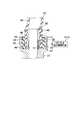
図7に見られるように、チューブ44の第2の接続端45は、管継手37のパッキン収容室42に入り込んでいる。この第2の接続端45の外周面と外壁39の内周面との間には、隙間が生じており、この隙間の部分にパッキン材47が充填されている。パッキン材47は、例えば吸水ポリマーを配合したゴム状弾性体であり、水分を吸収した時に、体積が増加するような特性を有している。このパッキン材47は、第2の接続端45の外周面および外壁39の内周面に夫々密接しており、チューブ44と管継手37との接続部分を外側から覆っている。
【0039】
さらに、外壁39の他端によって構成される挿入口40は、リング状のシール部材48によって塞がれている。シール部材48は、弾性変形が可能なゴム製であり、上記外壁39と協働してパッキン材47を覆い隠している。
【0040】
このような構成において、ポータブルコンピュータ1を長期間に亘って使用すると、チューブ44が管継手37の第1の接続端38の形状に馴染んだり、バンド46が弛む等して、チューブ44の内周面と第1の接続端38の外周面との密着性が失われることがあり得る。このような状態に陥ると、冷媒流路19を流れる冷却液の一部がチューブ44の内周面と第1の接続端38の外周面との間を伝わって漏れ出そうとする。
【0041】
しかるに、上記構成においては、チューブ44と管継手37との接続部分が外側から吸水性を有するパッキン材47で覆われているので、このパッキン材47が漏れた冷却液を吸収する。このため、冷却液は、管継手37のパッキン収容室42に止まり、管継手37の外部への冷却液の漏れを止める、もしくは冷却液の漏れ量を少なく抑えることができる。
【0042】
しかも、パッキン材47は、冷却液を吸収すると体積が増加する特性を有するので、このパッキン材47が外壁39の内周面およびチューブ44の第2の接続端45の外周面に押し付けられる。このため、チューブ44の第2の接続端45が外側から圧迫され、この第2の接続端45の内周面が第1の接続端38の外周面に押し付けられる。よって、チューブ44と管継手37の接続部分からの冷却液の漏れ出しを解消することができ、この冷却液が水気を嫌うプリント配線板9やCPU12に付着するのを防止できる。
【0043】
さらに、上記構成によると、パッキン収容室42に連なる挿入口40は、シール部材48によって塞がれているので、吸水性を有するパッキン材47が筐体4の内部に露出せずに済む。そのため、パッキン材47が空気中の湿気を吸収し難くなり、パッキン材47の吸水性能が早期のうちに飽和状態となるのを防止できる。よって、冷却液の漏れが生じた場合に、この漏れた冷却液をパッキン材47によって速やかに吸収することができる。
【0044】
なお、本発明は上記第1の実施の形態に特定されず、発明の趣旨を逸脱しない範囲内で種々変更して実施できる。例えば、パッキン材を取り囲む管継手の外壁に透明な窓を形成するとともに、吸水ポリマーに水分を吸った時に色の変化する物質を添加するようにしても良い。この構成によれば、窓を通じてパッキン材の色の変化具合を認識することができ、冷却液が漏れているか否かを目視により容易に確認できる。
【0045】
また、シール部材は必ずしも設置する必要はなく、パッキン材が挿入口から露出していても良い。
【0046】
さらに、図8ないし図10は、本発明の第2の実施の形態を開示している。
【0047】
この第2の実施の形態は、冷却液の漏れの有無を検知するとともに、この検知結果に基づいてポータブルコンピュータ1を制御するようにした点が上記第1の実施の形態と相違している。これ以外のポータブルコンピュータ1の基本的な構成は、上記第1の実施の形態と同様である。そのため、第2の実施の形態において、上記第1の実施の形態と同一の構成部分には同一の参照符号を付して、その説明を省略する。
【0048】
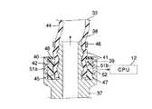
図8に示すように、管継手37の外壁39に一対の電極51a,51bが組み込まれている。電極51a,51bは、パッキン収容室42を間に挟んで互いに向かい合う位置に配置されている。これら電極51a,51bは、パッキン収容室42に露出しているとともに、パッキン材47に接している。このパッキン材47に導電性の冷却液が吸収されると、電極51a,51b間の電気抵抗値が下がり、この電気抵抗値を基に管継手37とチューブ44との接続部分からの冷却液の漏れの有無を検知している。そのため、上記電極51a,51bは、パッキン材47が冷却液を吸っているか否かを検知する検知手段52を構成している。
【0049】
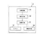
図9は、冷却液の漏れの有無に基づいてポータブルコンピュータ1を制御する際の機能ブロックを開示している。冷媒流路19、検知手段52およびCPU12は、コンピュータ本体2に収容されている。検知手段52によって検出された電気抵抗値は、CPU12に送られる。このCPU12は、電気抵抗値に基づいて冷却液が漏れているか否かを判断し、それ以降のポータブルコンピュータ1の動作を制御する。したがって、本実施の形態では、CPU12が制御手段を兼ねている。さらに、コンピュータ本体2は、冷却液が漏れていることを音で警告するスピーカあるいは光で表示するインディケータランプのような警告手段53を備えている。この警告手段53は、CPU12からの指令に基づいて動作する。
【0050】
図10は、ポータブルコンピュータ1の起動時のCPU12の動作を示すフローチャートを開示している。ステップS1においてポータブルコンピュータ1の電源が投入されると、CPU12は、ステップS2で通常値よりも低いクロック周波数で起動する。引き続きステップS3では、CPU12は、電極51a,51b間の電気抵抗値を基にパッキン材47が冷却液を吸っているか否かを判断する。
【0051】
このステップS3で冷却液が漏れていると判断されると、ステップS4に進む。このステップS4では、筐体4に収容された警告手段53がCPU12からの指令に基づき動作し、オペレ−タに冷却液が漏れていることを認識させる。この後、ステップS5に進み、CPU12は、ポータブルコンピュータ1をシャッドダウンさせる処理を実行する。
【0052】
一方、上記ステップS3で冷却液が漏れていないと判断された時は、ステップS6でポンプ20がCPU12からの指令を受けて動作を開始し、冷却ユニット16の受熱部17と放熱器18との間で冷却液が強制的に循環される。そして、次のステップS7でCPU12のクロック周波数を通常値に設定する処理を実行する。これにより、ポータブルコンピュータ1の起動動作が完了する。
【0053】
このような本発明の第2の実施の形態によれば、受熱部17の管継手37とチューブ44との接続部分から冷却液が漏れている時に、ポータブルコンピュータ1の起動時に冷却液の漏れを音や光で警告するとともに、このポータブルコンピュータ1を強制的にシャットダウンさせる処理を実行している。
【0054】
このため、冷却液の漏れが生じた時にポータブルコンピュータ1の動作を速やかに停止させることができ、冷却液の漏れを修復する作業に移行することができる。よって、ポータブルコンピュータ1のCPU12やその他の電子部品が冷却液によって致命的なダメージを受けるのを防止できる。
【0055】
図11および図12は、本発明の第3の実施の形態を開示している。
【0056】
この第3の実施の形態は、CPU12とは別の制御手段61を用いてポータブルコンピュータ1を制御するようにした点が上記第2の実施の形態と相違している。上記制御手段61は、プリント配線板9に実装されたLSIのような電子部品にて構成され、コンピュータ本体2に収容されている。
【0057】
図12は、ポータブルコンピュータ1の起動時の動作を示すフローチャートを開示している。ステップS11でポータブルコンピュータ1の電源が投入されると、冷却液が漏れているか否かを検知するステップS12に進む。このステップS12では、上記制御手段61に電極51a,51b間の電気抵抗値が入力される。制御手段61は、電気抵抗値を基にパッキン材47が冷却液を吸っているか否かを判断する。
【0058】
このステップS12で冷却液が漏れていると判断されると、ステップS13に進む。このステップS13では、筐体4に収容された警告手段53が制御手段61からの指令に基づき動作し、オペレータに冷却液が漏れていることを認識させる。この後、ステップS14に進み、制御手段61はポータブルコンピュータ1をシャットダウンさせる処理を実行する。
【0059】
一方、上記ステップS12で冷却液が漏れていないと判断された時は、ステップS15でポンプ20が制御手段61からの指令を受けて動作を開始し、冷却ユニット16の受熱部17と放熱器18との間で冷却液が強制的に循環される。そして、次のステップS16でCPU12が制御手段61からの指令を受けて起動する。これにより、ポータブルコンピュータ1の起動動作が完了する。
【0060】
このような本発明の第3の実施の形態によれば、ポータブルコンピュータ1の起動時に冷却液の漏れの有無を判断し、この判断結果に基づいてポータブルコンピュータ1を強制的にシャットダウンさせるか、CPU12を起動させる処理を実行している。そのため、冷却液の漏れが生じた時に、ポータブルコンピュータ1の動作を速やかに停止させることができ、CPU12やその他の電子部品が冷却液によって致命的なダメージを受けるのを防止できる。
【0061】
なお、この第3の実施の形態において、CPU12の熱を受ける受熱部17の熱容量が十分に大きい場合には、先にCPU12を起動させてから、ポンプ20を動作させるようにしても良い。
【0062】
図13は、本発明の第4の実施の形態を開示している。
【0063】
この第4の実施の形態は、冷却液の漏れが発生した場合でも、CPU12の冷却性能が維持されている限りポータブルコンピュータ1の動作を継続させるようにしたものである。それ以外の点は、上記第3の実施の形態と同様である。
【0064】
図13に示すように、ステップS21でポータブルコンピュータ1の電源が投入されると、冷却液が漏れているか否かを検知するステップS22に進む。このステップS22では、制御手段61に電極51a,51b間の電気抵抗値が入力される。制御手段61は、電気抵抗値を基にパッキン材47が冷却液を吸っているか否かを判断する。このステップS22で冷却液が漏れていないと判断された時は、冷却液が漏れているか否かを検知する処理を繰り返す。
【0065】
ステップS22で冷却液が漏れていると判断されると、ステップS23に進む。このステップS23では、筐体4に収容された警告手段53が制御手段61からの指令に基づき動作し、オペレータに冷却液が漏れていることを認識させる。引き続いてステップS24に進み、制御手段61がポンプ20の運転を停止させる処理を実行する。これにより、受熱部17と放熱器18との間での冷却液の循環が停止する。
【0066】
冷却液の循環が止まると、制御手段61はステップS25においてCPU12のクロック周波数を通常値よりも低く設定する処理を実行し、CPU12の発熱を抑える。次にステップS26に進み、ここで制御手段61は、その時のCPU12の温度を予め設定された上限値と比較する。CPU12の温度が上限値よりも低い場合には、CPU12の温度と上限値とを比較する処理を繰り返す。
【0067】
上記ステップS26でCPU12の温度が上限値を上回った場合は、ステップS27に進み、制御手段61はポータブルコンピュータ1をシャットダウンさせる処理を実行する。
【0068】
このような第4の実施の形態によれば、冷却液の漏れが検出された場合に、冷却液の循環が停止されるので、管継手37とチューブ44との接続部分からの冷却液の漏れを止めることができる。
【0069】
しかも、冷却液の循環が止まった以降は、CPU12のクロック周波数を通常値よりも低く設定して、CPU12の発熱を抑えるとともに、このCPU12の温度を監視しつつポータブルコンピュータ1の運転を継続している。そのため、冷却液の漏れが生じた時に、直ちにポータブルコンピュータ1の運転を停止させることができないような使用形態に好都合となる。
【0070】
図14は、本発明の第5の実施の形態を開示している。
【0071】
この第5の実施の形態は、冷却液の漏れが発生した時に、直ちにポータブルコンピュータ1の動作を停止させるようにした点が上記第4の実施の形態と相違している。
【0072】
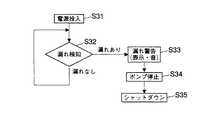
図14に示すように、ステップS31でポータブルコンピュータ1の電源が投入されると、冷却液が漏れているか否かを検知するステップS32に進む。このステップS32では、制御手段61に電極51a,51b間の電気抵抗値が入力される。制御手段61は、電気抵抗値を基にパッキン材47が冷却液を吸っているか否かを判断する。このステップS32で冷却液が漏れていないと判断された時は、冷却液が漏れているか否かを検知する処理を繰り返す。
【0073】
ステップS32で冷却液が漏れていると判断されると、ステップS33に進む。このステップS33では、筐体4に収容された警告手段53が制御手段61からの指令に基づき動作し、オペレータに冷却液が漏れていることを認識させる。引き続いてステップS34に進み、制御手段61がポンプ20の運転を停止させる処理を実行する。これにより、受熱部17と放熱器18との間での冷却液の循環が停止する。次に、ステップS35に進み、制御手段61は、ポータブルコンピュータ1をシャットダウンさせる処理を実行する。
【0074】
さらに、図15は、本発明の第6の実施の形態を開示している。
【0075】
この第6の実施の形態は、パッキン材47が冷却液を吸っているか否かを検知するための構成が上記第2の実施の形態と相違している。これ以外のポータブルコンピュータ1の基本的な構成は、上記第2の実施の形態と同様である。
【0076】
図15に示すように、管継手37の第1の接続端38の内部に第1の電極71が埋め込まれている。さらに、管継手37の外壁39の内部に第2の電極72が埋め込まれている。パッキン材47は、第1および第2の電極71,72の間に介在されている。パッキン材47に導電性の冷却液が吸収されると、第1および第2の電極71,72の間の静電容量が変化し、この静電容量の変化を示す信号がCPU12又は他の制御手段61に送出される。したがって、第1および第2の電極71,72は、パッキン材47が冷却液を吸っているか否かを検知する検知手段73を構成している。
【0077】
このような第6の実施の形態においても、第1および第2の電極71,72からの信号をCPU12又はCPU12とは別の制御手段61に入力することにより、冷却液が漏れているか否かを判断することができる。したがって、上記第2ないし第5の実施の形態と同様に、冷却液の漏れの有無に基づいてポータブルコンピュータ1を起動させたり、強制的にシャットダウンさせる処理を実行することができ、漏れた冷却液によりCPU12やその他の電子部品が致命的なダメージを受けるのを防止できる。
【0078】
【発明の効果】
以上詳述した本発明によれば、冷媒流路からの冷媒の漏れを防止できるとともに、たとえ冷媒に漏れが生じたとしても、漏れた冷媒によってCPUのような発熱体が致命的なダメージを受けずに済むといった利点がある。
【図面の簡単な説明】
【図1】本発明の第1の実施の形態において、液冷式の冷却ユニットを搭載したポータブルコンピュータの斜視図。
【図2】本発明の第1の実施の形態において、ディスプレイユニットを開き位置に回動させた状態を示すポータブルコンピュータの斜視図。
【図3】本発明の第1の実施の形態において、液冷式の冷却ユニットを搭載したポータブルコンピュータの断面図。
【図4】本発明の第1の実施の形態において、CPUと受熱部との位置関係を示すポータブルコンピュータの断面図。
【図5】本発明の第1の実施の形態に用いる受熱部の断面図。
【図6】本発明の第1の実施の形態に用いる放熱器の断面図。
【図7】本発明の第1の実施の形態において、冷却液の漏れ防止対策を施した管継手とチューブとの接続部分の断面図。
【図8】本発明の第2の実施の形態において、冷却液の漏れ防止対策を施した管継手とチューブとの接続部分の断面図。
【図9】本発明の第2の実施の形態の機能を示すブロック図。
【図10】本発明の第2の実施の形態において、冷却液の漏れを検知してからポータブルコンピュータをシャットダウンするまでの制御の内容を示すフローチャート。
【図11】本発明の第3の実施の形態の機能を示すブロック図。
【図12】本発明の第3の実施の形態において、冷却液の漏れを検知してからポータブルコンピュータをシャットダウンするまでの制御の内容を示すフローチャート。
【図13】本発明の第4の実施の形態において、冷却液の漏れを検知してからポータブルコンピュータをシャットダウンするまでの制御の内容を示すフローチャート。
【図14】本発明の第5の実施の形態において、冷却液の漏れを検知してからポータブルコンピュータをシャットダウンするまでの制御の内容を示すフローチャート。
【図15】本発明の第6の実施の形態において、冷却液の漏れ防止対策を施した管継手とチューブとの接続部分の断面図。
【符号の説明】
4…筐体
12…発熱体(CPU)
19…冷媒流路
37…第1の管路(管継手)
44…第2の管路(チューブ)
47…パッキン材
52,73…検知手段
12,61…制御手段[0001]
BACKGROUND OF THE INVENTION
The present invention relates to a liquid-cooled electronic device that cools a heating element such as a CPU using a liquid refrigerant, and more particularly to a structure that prevents leakage of the refrigerant from a connection portion of a refrigerant flow path.
[0002]
[Prior art]
For example, CPUs used in notebook type portable computers have increased heat generation during operation as the processing speed increases and the number of functions increases. Therefore, in recent years, a so-called liquid cooling type cooling system has been developed in which the CPU is cooled using a liquid refrigerant having a specific heat far higher than that of air.
[0003]
Japanese Patent Laid-Open No. 7-142886 discloses an example of a liquid cooling type cooling system used for a portable computer. This cooling system includes a heat receiving header, a heat radiating header, and a tube for circulating the refrigerant. The heat receiving header is housed in the casing of the portable computer and is thermally connected to the CPU. The heat dissipation header is accommodated in the display device of the portable computer. The tube is piped across the housing and the display device, and connects between the heat receiving header and the heat radiating header.
[0004]
According to this cooling system, the heat of the CPU is transferred to the refrigerant by heat exchange in the heat receiving header. The refrigerant heated by the heat receiving header is transferred to the heat radiating header through the tube and releases the CPU heat in the process of passing through the heat radiating header. The refrigerant cooled by the heat exchange in the heat radiating header is returned to the heat receiving header through the tube and receives the heat of the CPU again. Due to the circulation of the refrigerant, the heat of the CPU can be efficiently transferred to the heat dissipation header, and the cooling performance of the CPU is enhanced.
[0005]
By the way, in the liquid cooling type cooling system, since the liquid refrigerant is circulated between the heat receiving header and the heat radiating header, there is a possibility that some refrigerant leaks from the circulation path of the refrigerant. As a part where the leakage of the refrigerant is likely to occur, for example, a connection part between a part such as a heat receiving header and the tube is listed. In a conventional cooling system, pipe joints are installed at the refrigerant inlet and the refrigerant outlet of the heat receiving header, and the end of the tube is inserted into the pipe joint to connect the heat receiving header and the tube. Furthermore, in order to make the connection stronger, the connecting portion between the tube and the pipe joint is tightened with a band from the outside to prevent the tube from dropping off from the pipe joint.
[0006]
[Problems to be solved by the invention]
In a liquid-cooled cooling system, even if there is a slight leak in the refrigerant circulation path or a small amount of air bubbles in the circulation path, the cooling performance of the CPU will be extremely deteriorated as long as there is no special problem with the refrigerant circulation. Never do.
[0007]
However, if the refrigerant leaks over a certain amount, it is inevitable that the leaked refrigerant adheres to the CPU and various electronic components in the housing. In particular, the refrigerant containing the antifreeze has electrical conductivity, which causes fatal damage to the CPU and electronic components, which may make the portable computer inoperable. Furthermore, if the leaked refrigerant flows out of the housing, it also stains, for example, clothes and desks, which adversely affects the usage environment of the portable computer.
[0008]
In addition, according to the connection structure between the conventional tube and the heat receiving head, the tube may become familiar with the shape of the pipe joint after long-term use, or the force that tightens the pipe joint may be lost due to loosening of the band. obtain. If it falls into such a state, it will become impossible to stop the leakage of the refrigerant | coolant from the connection part of a tube and a pipe joint, and there exists a problem that the leaked refrigerant | coolant flows out inside a housing | casing.
[0009]
On the other hand, for example, “Japanese Patent Laid-Open No. 4-258591” discloses a configuration for preventing leakage of liquid from a connecting portion of a pipe. In this prior art, a tubular packing member is attached to the connection end of one pipe, and a tubular press-fit member is attached to the connection end of the other pipe. The packing member and the press-fitting member are formed of a rubber material blended with a highly water-absorbing polymer.
[0010]
According to this prior art, the packing member and the press-fitting member are in pressure contact with each other between the connection end of one pipe and the connection end of the other pipe, and a liquid is connected between the connection ends of these pipes. It is tightly sealed.
[0011]
However, in the above prior art, since the press-fitting member is fitted inside the packing member, a special stopper is required to be fixed to the connection end of the pipe so that the packing member and the press-fitting member are not displaced at the time of the fitting. A plurality of engaging portions for engaging the packing member and the press-fitting member with each other are required.
[0012]
As a result, it is inevitable that the shapes of the packing member and the press-fitting member are complicated, and there arises a cost problem in that the individual unit price increases. In addition, the above prior art only discloses a connection structure for pressure piping of a high-rise apartment, and the field is different from that of an electronic device such as a portable computer with a built-in electronic component. No mention is made of application to cooling systems.
[0013]
The object of the present invention is to prevent leakage of refrigerant from the refrigerant flow path,Even if the refrigerant leaks, the leaked refrigerantCPUHeating elements such as can avoid fatal damageTo get electronic equipment.
[0014]
[Means for Solving the Problems]
In order to achieve the above object, an electronic apparatus according to the present invention provides:
A housing for housing the heating element;
A refrigerant channel having a first pipeline and a second pipeline connected to the first pipeline, through which a liquid refrigerant for cooling the heating element flows;
Connection portion between the first pipeline and the second pipelineCoveringA packing material having water absorption,
Detecting means for detecting whether or not the packing material sucks the refrigerant;
Control means for determining that the refrigerant is leaking from a connecting portion between the first pipe line and the second pipe line when the presence of the refrigerant is detected by the detection means, and stopping the operation of the device; Having providedIt is characterized by.
According to this configuration, when the refrigerant leaks from the connection portion between the first pipe line and the second pipe line, the packing material absorbs the refrigerant.To do.This absorption increases the volume of the packing material,PipelinePress the connection part from the outside. Therefore,PipelineLeakage of the refrigerant from the connection portion can be prevented.
At the same time, if the refrigerant leaks from the connection part of the pipeline, the operation of the electronic device stops.CPUA heating element such as can avoid fatal damage.
[0015]
DETAILED DESCRIPTION OF THE INVENTION
A first embodiment of the present invention will be described below with reference to FIGS.
[0016]
1 to 3 disclose a
[0017]
The
[0018]
Therefore, the
[0019]
As shown in FIGS. 1 and 3, the housing 4 accommodates a printed
[0020]
As shown in FIG. 4, a
[0021]
The
[0022]
As shown in FIGS. 4 and 5, the
[0023]
Further, a
[0024]
The
[0025]
The first
[0026]
The
[0027]
As shown in FIGS. 1 and 3, the
[0028]
The
[0029]
When the
[0030]
The cooling liquid cooled by heat exchange in the
[0031]
In such a liquid cooling
[0032]
Therefore, in the present invention, measures for preventing the leakage of the coolant are taken at the connecting portion. This leakage prevention measure will be described on behalf of the connecting portion between the
[0033]
As shown in FIGS. 5 and 7, the
[0034]
One end of the
[0035]
A packing
[0036]
On the other hand, the
[0037]
Further, the second connection end 45 of the
[0038]
As seen in FIG. 7, the second connection end 45 of the
[0039]
Further, the
[0040]
In such a configuration, when the
[0041]
However, in the above-described configuration, the connecting portion between the
[0042]
In addition, since the packing
[0043]
Furthermore, according to the above configuration, the
[0044]
It should be noted that the present invention is not limited to the first embodiment, and can be implemented with various modifications without departing from the spirit of the invention. For example, a transparent window may be formed on the outer wall of a pipe joint that surrounds the packing material, and a substance that changes color when moisture is absorbed into the water-absorbing polymer may be added. According to this configuration, the color change of the packing material can be recognized through the window, and it can be easily confirmed by visual observation whether or not the coolant is leaking.
[0045]
Further, the seal member is not necessarily installed, and the packing material may be exposed from the insertion port.
[0046]
Further, FIGS. 8 to 10 disclose a second embodiment of the present invention.
[0047]
The second embodiment is different from the first embodiment in that the presence or absence of leakage of the coolant is detected and the
[0048]
As shown in FIG. 8, a pair of
[0049]
FIG. 9 discloses functional blocks for controlling the
[0050]
FIG. 10 discloses a flowchart showing the operation of the
[0051]
If it is determined in step S3 that the coolant is leaking, the process proceeds to step S4. In this step S4, the warning means 53 accommodated in the housing 4 operates based on a command from the
[0052]
On the other hand, when it is determined in step S3 that the coolant is not leaking, in step S6, the
[0053]
According to the second embodiment of the present invention, when the coolant leaks from the connection portion between the pipe joint 37 and the
[0054]
Therefore, the operation of the
[0055]
11 and 12 disclose a third embodiment of the present invention.
[0056]
The third embodiment is different from the second embodiment in that the
[0057]
FIG. 12 discloses a flowchart showing the operation when the
[0058]
If it is determined in step S12 that the coolant is leaking, the process proceeds to step S13. In this step S13, the warning means 53 accommodated in the housing 4 operates based on a command from the control means 61, and makes the operator recognize that the coolant is leaking. Thereafter, the process proceeds to step S14, where the control means 61 executes a process for shutting down the
[0059]
On the other hand, when it is determined in step S12 that the coolant is not leaking, the
[0060]
According to the third embodiment of the present invention as described above, it is determined whether or not the coolant leaks when the
[0061]
In the third embodiment, when the heat capacity of the
[0062]
FIG. 13 discloses a fourth embodiment of the present invention.
[0063]
In the fourth embodiment, even when the coolant leaks, the operation of the
[0064]
As shown in FIG. 13, when the
[0065]
If it is determined in step S22 that the coolant is leaking, the process proceeds to step S23. In this step S23, the warning means 53 accommodated in the housing 4 operates based on a command from the control means 61, and makes the operator recognize that the coolant is leaking. Then, it progresses to step S24 and the control means 61 performs the process which stops the driving | operation of the
[0066]
When the circulation of the coolant stops, the control means 61 executes a process of setting the clock frequency of the
[0067]
If the temperature of the
[0068]
According to the fourth embodiment, since the circulation of the cooling liquid is stopped when the leakage of the cooling liquid is detected, the leakage of the cooling liquid from the connection portion between the pipe joint 37 and the
[0069]
In addition, after the circulation of the coolant is stopped, the clock frequency of the
[0070]
FIG. 14 discloses a fifth embodiment of the present invention.
[0071]
The fifth embodiment is different from the fourth embodiment in that the operation of the
[0072]
As shown in FIG. 14, when the
[0073]
If it is determined in step S32 that the coolant is leaking, the process proceeds to step S33. In this step S33, the warning means 53 accommodated in the housing 4 operates based on a command from the control means 61, and makes the operator recognize that the coolant is leaking. Subsequently, the process proceeds to step S34, where the control means 61 executes a process for stopping the operation of the
[0074]
Further, FIG. 15 discloses a sixth embodiment of the present invention.
[0075]
The sixth embodiment is different from the second embodiment in the configuration for detecting whether or not the packing
[0076]
As shown in FIG. 15, the first electrode 71 is embedded inside the
[0077]
Also in the sixth embodiment, whether or not the coolant leaks by inputting the signals from the first and
[0078]
【The invention's effect】
According to the present invention detailed above,Refrigerant flow pathPrevents leakage of refrigerant from theEven if the refrigerant leaks, the leaked refrigerantCPUThere is an advantage that a heating element such as can avoid fatal damage.
[Brief description of the drawings]
FIG. 1 is a perspective view of a portable computer equipped with a liquid cooling type cooling unit according to a first embodiment of the present invention.
FIG. 2 is a perspective view of the portable computer showing a state in which the display unit is rotated to an open position in the first embodiment of the present invention.
FIG. 3 is a cross-sectional view of a portable computer equipped with a liquid cooling type cooling unit in the first embodiment of the present invention.
FIG. 4 is a cross-sectional view of a portable computer showing a positional relationship between a CPU and a heat receiving unit in the first embodiment of the present invention.
FIG. 5 is a cross-sectional view of a heat receiving portion used in the first embodiment of the present invention.
FIG. 6 is a cross-sectional view of a radiator used in the first embodiment of the present invention.
FIG. 7 is a cross-sectional view of a connecting portion between a pipe joint and a tube, in which measures for preventing leakage of cooling liquid are taken, in the first embodiment of the present invention.
FIG. 8 is a cross-sectional view of a connection portion between a pipe joint and a tube, in which measures for preventing leakage of coolant are taken, in the second embodiment of the present invention.
FIG. 9 is a block diagram showing functions of a second embodiment of the present invention.
FIG. 10 is a flowchart showing the contents of control from when a leakage of coolant is detected until the portable computer is shut down in the second embodiment of the present invention.
FIG. 11 is a block diagram showing functions of a third embodiment of the present invention.
FIG. 12 is a flowchart showing the contents of control from when a leakage of coolant is detected until the portable computer is shut down in the third embodiment of the present invention.
FIG. 13 is a flowchart showing the contents of control from when a leakage of coolant is detected until the portable computer is shut down in the fourth embodiment of the present invention.
FIG. 14 is a flowchart showing the contents of control from when a leakage of coolant is detected until the portable computer is shut down in the fifth embodiment of the present invention.
FIG. 15 is a cross-sectional view of a connecting portion between a pipe joint and a tube, in which measures for preventing leakage of coolant are taken, in a sixth embodiment of the present invention.
[Explanation of symbols]
4 ... Case
12 ... Heating element (CPU)
19 ... Refrigerant flow path
37 ... 1st pipe line (pipe joint)
44 ... Second pipe (tube)
47 ... Packing material
52, 73 ... detection means
12, 61 ... Control means
Claims (8)
Translated fromJapanese第1の管路と、この第1の管路に接続された第2の管路とを有し、上記発熱体を冷却する液状の冷媒が流れる冷媒流路と、
上記第1の管路と上記第2の管路との接続部分を覆う吸水性を有するパッキン材と、
上記パッキン材が上記冷媒を吸っているか否かを検知する検知手段と、
上記検知手段によって上記冷媒の存在が検知された時に、上記第1の管路と上記第2の管路との接続部分から冷媒が漏れていると判断し、機器の動作を停止させる制御手段と、を具備したことを特徴とする電子機器。A housing for housing the heating element;
A refrigerant passage having a first duct and a second duct connected to the first duct, through which a liquid refrigerant for cooling the heating element flows;
A packing material having water absorption covering a connecting portion between the first pipe line and the second pipe line;
Detecting means for detecting whether or not the packing material sucks the refrigerant;
Control means for determining that the refrigerant is leaking from a connecting portion between the first pipe line and the second pipe line when the presence of the refrigerant is detected by the detection means, and stopping the operation of the device; electronic apparatus, characterized inthat, equipped with a.
第1の管路と、この第1の管路に接続された第2の管路とを有し、上記CPUを冷却する液状の冷媒が流れる冷媒流路と、
上記第1の管路と上記第2の管路との接続部分を覆う吸水性を有するパッキン材と、
上記パッキン材が上記冷媒を吸っているか否かを検知する検知手段と、を具備し、
上記CPUは、機器の電源が投入された時に、通常時よりも低いクロック周波数で起動し、上記検知手段によって上記冷媒の存在が検知された時に、上記第1の管路と上記第2の管路との接続部分から冷媒が漏れていると判断して機器の動作を停止させるとともに、上記検知手段によって上記冷媒の存在が検知されなかった時に、その周波数を通常値に設定することを特徴とする電子機器。A housing havingaCPUthatgenerates heat;
Arefrigerant flow pathhaving a first pipeline and a second pipeline connected to the first pipeline,through which a liquid refrigerant for cooling theCPUflows;
A packing material having water absorption covering a connecting portion between the first pipe line and the second pipe line;
Detecting means for detecting whether or not the packing material is sucking the refrigerant,
TheCPUstarts up at a clock frequency lower than normal when the device is turned on, and when the detection means detects the presence of the refrigerant, theCPUand the second pipe It is judged that the refrigerant is leaking from the connection portion with the road and stops the operation of the device, and when the presence of the refrigerant is not detected by the detection means, the frequency is set to a normal value. Electronic equipment.
Priority Applications (3)
| Application Number | Priority Date | Filing Date | Title |
|---|---|---|---|
| JP2002245372AJP3641258B2 (en) | 2002-08-26 | 2002-08-26 | Electronics |
| CNB03155301XACN1320417C (en) | 2002-08-26 | 2003-08-26 | Electronic apparatus having a circulating path of liquid coolant |
| US10/647,332US7142425B2 (en) | 2002-08-26 | 2003-08-26 | Liquid cooling system including a liquid absorption and a leak detection device |
Applications Claiming Priority (1)
| Application Number | Priority Date | Filing Date | Title |
|---|---|---|---|
| JP2002245372AJP3641258B2 (en) | 2002-08-26 | 2002-08-26 | Electronics |
Publications (2)
| Publication Number | Publication Date |
|---|---|
| JP2004087688A JP2004087688A (en) | 2004-03-18 |
| JP3641258B2true JP3641258B2 (en) | 2005-04-20 |
Family
ID=32053577
Family Applications (1)
| Application Number | Title | Priority Date | Filing Date |
|---|---|---|---|
| JP2002245372AExpired - Fee RelatedJP3641258B2 (en) | 2002-08-26 | 2002-08-26 | Electronics |
Country Status (3)
| Country | Link |
|---|---|
| US (1) | US7142425B2 (en) |
| JP (1) | JP3641258B2 (en) |
| CN (1) | CN1320417C (en) |
Families Citing this family (75)
| Publication number | Priority date | Publication date | Assignee | Title |
|---|---|---|---|---|
| US6606251B1 (en) | 2002-02-07 | 2003-08-12 | Cooligy Inc. | Power conditioning module |
| US6988534B2 (en) | 2002-11-01 | 2006-01-24 | Cooligy, Inc. | Method and apparatus for flexible fluid delivery for cooling desired hot spots in a heat producing device |
| WO2004036040A1 (en) | 2002-09-23 | 2004-04-29 | Cooligy, Inc. | Micro-fabricated electrokinetic pump with on-frit electrode |
| US6994151B2 (en) | 2002-10-22 | 2006-02-07 | Cooligy, Inc. | Vapor escape microchannel heat exchanger |
| US7156159B2 (en) | 2003-03-17 | 2007-01-02 | Cooligy, Inc. | Multi-level microchannel heat exchangers |
| US7000684B2 (en) | 2002-11-01 | 2006-02-21 | Cooligy, Inc. | Method and apparatus for efficient vertical fluid delivery for cooling a heat producing device |
| AU2003286821A1 (en)* | 2002-11-01 | 2004-06-07 | Cooligy, Inc. | Optimal spreader system, device and method for fluid cooled micro-scaled heat exchange |
| US6986382B2 (en) | 2002-11-01 | 2006-01-17 | Cooligy Inc. | Interwoven manifolds for pressure drop reduction in microchannel heat exchangers |
| US7836597B2 (en) | 2002-11-01 | 2010-11-23 | Cooligy Inc. | Method of fabricating high surface to volume ratio structures and their integration in microheat exchangers for liquid cooling system |
| WO2004042306A2 (en) | 2002-11-01 | 2004-05-21 | Cooligy, Inc. | Method and apparatus for achieving temperature uniformity and hot spot cooling in a heat producing device |
| US7090001B2 (en) | 2003-01-31 | 2006-08-15 | Cooligy, Inc. | Optimized multiple heat pipe blocks for electronics cooling |
| US7293423B2 (en) | 2004-06-04 | 2007-11-13 | Cooligy Inc. | Method and apparatus for controlling freezing nucleation and propagation |
| US7201012B2 (en) | 2003-01-31 | 2007-04-10 | Cooligy, Inc. | Remedies to prevent cracking in a liquid system |
| US7017654B2 (en) | 2003-03-17 | 2006-03-28 | Cooligy, Inc. | Apparatus and method of forming channels in a heat-exchanging device |
| US6942719B2 (en)* | 2003-06-30 | 2005-09-13 | The Boeing Company | Methods and systems for pressure swing regeneration for hydrogen generation |
| US7021369B2 (en)* | 2003-07-23 | 2006-04-04 | Cooligy, Inc. | Hermetic closed loop fluid system |
| US7616444B2 (en) | 2004-06-04 | 2009-11-10 | Cooligy Inc. | Gimballed attachment for multiple heat exchangers |
| US7188662B2 (en) | 2004-06-04 | 2007-03-13 | Cooligy, Inc. | Apparatus and method of efficient fluid delivery for cooling a heat producing device |
| JP2006156711A (en) | 2004-11-30 | 2006-06-15 | Mitsubishi Electric Corp | Power semiconductor module cooling system |
| JP4358170B2 (en)* | 2005-08-30 | 2009-11-04 | 株式会社東芝 | Liquid leak detection structure |
| US20070069420A1 (en)* | 2005-09-29 | 2007-03-29 | Intel Corporation | Method and apparatus to generate a seal between metallic and plastic materials |
| US20070169374A1 (en)* | 2006-01-23 | 2007-07-26 | Qnx Cooling Systems Inc. | Cooling system leak detector |
| WO2007120530A2 (en) | 2006-03-30 | 2007-10-25 | Cooligy, Inc. | Integrated liquid to air conduction module |
| US7715194B2 (en) | 2006-04-11 | 2010-05-11 | Cooligy Inc. | Methodology of cooling multiple heat sources in a personal computer through the use of multiple fluid-based heat exchanging loops coupled via modular bus-type heat exchangers |
| CN101517185B (en)* | 2006-07-18 | 2013-06-12 | 力博特公司 | Integral swivel hydraulic connectors, door hinges, and methods and systems for the use thereof |
| US7978474B2 (en)* | 2007-05-22 | 2011-07-12 | Apple Inc. | Liquid-cooled portable computer |
| TW200934352A (en) | 2007-08-07 | 2009-08-01 | Cooligy Inc | Internal access mechanism for a server rack |
| US9496200B2 (en) | 2011-07-27 | 2016-11-15 | Coolit Systems, Inc. | Modular heat-transfer systems |
| US9453691B2 (en) | 2007-08-09 | 2016-09-27 | Coolit Systems, Inc. | Fluid heat exchange systems |
| US20090225514A1 (en) | 2008-03-10 | 2009-09-10 | Adrian Correa | Device and methodology for the removal of heat from an equipment rack by means of heat exchangers mounted to a door |
| WO2009139065A1 (en)* | 2008-05-16 | 2009-11-19 | Necディスプレイソリューションズ株式会社 | Cooling pump unit and projection display apparatus having the same |
| KR101013555B1 (en)* | 2008-10-09 | 2011-02-14 | 주식회사 하이닉스반도체 | Semiconductor package and manufacturing method thereof |
| US20100328885A1 (en)* | 2009-06-26 | 2010-12-30 | Scofield William H | Rotatable Cooling Module |
| JP5403426B2 (en)* | 2009-11-24 | 2014-01-29 | 株式会社リコー | Image forming apparatus |
| US20120251859A1 (en)* | 2011-03-31 | 2012-10-04 | Lg Chem, Ltd. | Battery pack having liquid leak detection system |
| CN102819303A (en)* | 2011-06-09 | 2012-12-12 | 鸿富锦精密工业(深圳)有限公司 | Computer case |
| US10365667B2 (en) | 2011-08-11 | 2019-07-30 | Coolit Systems, Inc. | Flow-path controllers and related systems |
| US9127813B2 (en) | 2012-02-23 | 2015-09-08 | Lenovo Enterprise (Singapore) Pte. Ltd. | Responding to moisture at one or more zones around an outer surface of a liquid-carrying pipe |
| JP2013222914A (en)* | 2012-04-19 | 2013-10-28 | Hitachi Ltd | Liquid leakage prevention device and method, and liquid cooling system |
| KR102015565B1 (en)* | 2012-06-04 | 2019-08-28 | 삼성전자주식회사 | Electronic device and method for controlling temperature thereof |
| US8436246B1 (en)* | 2012-10-19 | 2013-05-07 | Calvary Applied Technologies, LLC | Refrigerant line electrical ground isolation device for data center cooling applications |
| US9335355B2 (en)* | 2013-03-06 | 2016-05-10 | Apple Inc. | Electronic device with liquid contact sensors |
| US12366870B2 (en) | 2013-03-15 | 2025-07-22 | Coolit Systems, Inc. | Flow-path controllers and related systems |
| US10364809B2 (en) | 2013-03-15 | 2019-07-30 | Coolit Systems, Inc. | Sensors, multiplexed communication techniques, and related systems |
| US9869983B2 (en) | 2014-12-05 | 2018-01-16 | International Business Machines Corporation | Cooling system leak detection |
| US20160178475A1 (en)* | 2014-12-17 | 2016-06-23 | Intel Corporation | Leak detection in liquid cooled computing systems |
| CN105549703A (en)* | 2015-12-11 | 2016-05-04 | 曙光信息产业(北京)有限公司 | Cooling system and method of server |
| CN105511578A (en)* | 2015-12-23 | 2016-04-20 | 曙光信息产业(北京)有限公司 | Heat dissipation method and device of server |
| US11137314B2 (en)* | 2018-03-07 | 2021-10-05 | Steering Solutions Ip Holding Corporation | Water intrusion detection |
| CN110243552B (en)* | 2018-03-09 | 2022-04-22 | 深圳光峰科技股份有限公司 | Anti-leakage system and cooling system |
| US10802556B2 (en)* | 2018-04-13 | 2020-10-13 | Dell Products L.P. | Information handling system thermal fluid hinge |
| US10969841B2 (en) | 2018-04-13 | 2021-04-06 | Dell Products L.P. | Information handling system housing integrated vapor chamber |
| US10936031B2 (en) | 2018-04-13 | 2021-03-02 | Dell Products L.P. | Information handling system dynamic thermal transfer control |
| TWI725422B (en)* | 2018-05-31 | 2021-04-21 | 技嘉科技股份有限公司 | Liquid cooling device, coolant circulation system , and liquid leaking detection method |
| US11662037B2 (en) | 2019-01-18 | 2023-05-30 | Coolit Systems, Inc. | Fluid flow control valve for fluid flow systems, and methods |
| US11473860B2 (en) | 2019-04-25 | 2022-10-18 | Coolit Systems, Inc. | Cooling module with leak detector and related systems |
| US10859461B2 (en)* | 2019-05-01 | 2020-12-08 | Dell Products, L.P. | Method and apparatus for digital leak detection in liquid-cooled information handling systems |
| CN110134214A (en)* | 2019-05-29 | 2019-08-16 | 英业达科技有限公司 | Portable electronic devices |
| US11346741B2 (en)* | 2019-05-29 | 2022-05-31 | Dell Products L.P. | Detecting leaks in liquid-cooled information handling systems with moisture wicking material |
| CN110418549B (en)* | 2019-06-18 | 2021-01-29 | 华为技术有限公司 | Heat dissipation assembly and electronic equipment |
| WO2020262739A1 (en)* | 2019-06-28 | 2020-12-30 | 엘지전자 주식회사 | Avn device |
| JP6927603B2 (en)* | 2019-11-13 | 2021-09-01 | Necプラットフォームズ株式会社 | Cooling system, electronic equipment |
| US11435108B2 (en)* | 2020-04-14 | 2022-09-06 | E. K. Fox & Associates, Ltd. | Apparatus for non-conductive refrigerant line break |
| WO2021229365A1 (en) | 2020-05-11 | 2021-11-18 | Coolit Systems, Inc. | Liquid pumping units, and related systems and methods |
| CN111710467B (en)* | 2020-06-24 | 2022-04-05 | 桂林国际电线电缆集团有限责任公司 | High-temperature-resistant insulated safety wire arrangement structure |
| US12216025B2 (en)* | 2021-03-08 | 2025-02-04 | Baidu Usa Llc | Advanced sealing structure for liquid cooling |
| US11725886B2 (en) | 2021-05-20 | 2023-08-15 | Coolit Systems, Inc. | Modular fluid heat exchange systems |
| US11991867B2 (en) | 2021-05-21 | 2024-05-21 | Quanta Computer Inc. | Closed-loop liquid cooling system |
| CN114040665B (en)* | 2021-12-01 | 2022-07-26 | 博浩数据信息技术(广州)有限公司 | Box type liquid cooling equipment for data center |
| US12200914B2 (en) | 2022-01-24 | 2025-01-14 | Coolit Systems, Inc. | Smart components, systems and methods for transferring heat |
| US20230364527A1 (en)* | 2022-05-16 | 2023-11-16 | Microsoft Technology Licensing, Llc | Absorbent pad for leak mitigation |
| US12389562B2 (en) | 2022-10-20 | 2025-08-12 | Dell Products L.P. | Floor track and mounting apparatus for modular data centers |
| US12309979B2 (en)* | 2022-10-20 | 2025-05-20 | Dell Products L.P. | Adjustable hinged mounting bracket for a computing device |
| US12238887B2 (en) | 2022-10-20 | 2025-02-25 | Dell Products L.P. | Mounting apparatus for components without mounting points in modular data centers |
| CN115950608B (en)* | 2023-02-22 | 2023-06-02 | 苏州浪潮智能科技有限公司 | Liquid leakage detection circuit, system, method, electronic device and storage medium |
Family Cites Families (21)
| Publication number | Priority date | Publication date | Assignee | Title |
|---|---|---|---|---|
| US2477533A (en)* | 1946-10-19 | 1949-07-26 | William A Whiting | Pipe joint |
| JPS58106852A (en)* | 1981-12-18 | 1983-06-25 | Mitsubishi Electric Corp | Power semiconductor equipment |
| US4990541A (en)* | 1989-11-09 | 1991-02-05 | Hoechst Celanese Corp. | Water absorbent latex polymer foams |
| US5323847A (en)* | 1990-08-01 | 1994-06-28 | Hitachi, Ltd. | Electronic apparatus and method of cooling the same |
| JPH04258591A (en)* | 1991-02-14 | 1992-09-14 | Noriatsu Kojima | Pipe connecting device |
| JPH0810103B2 (en)* | 1993-07-22 | 1996-01-31 | 日本電気株式会社 | Structure of cooling pipe connection part of water cooling unit |
| JP3385482B2 (en) | 1993-11-15 | 2003-03-10 | 株式会社日立製作所 | Electronics |
| US5383340A (en)* | 1994-03-24 | 1995-01-24 | Aavid Laboratories, Inc. | Two-phase cooling system for laptop computers |
| DE19751361A1 (en)* | 1997-11-20 | 1999-05-27 | Itt Mfg Enterprises Inc | Connection element for pipes or hoses |
| JPH11346079A (en)* | 1998-05-29 | 1999-12-14 | Ando Electric Co Ltd | Cooling device of electronic apparatus |
| US6776421B2 (en)* | 2000-02-10 | 2004-08-17 | Delphi Technologies, Inc. | Fluid sealing system |
| JP3556578B2 (en)* | 2000-06-29 | 2004-08-18 | 株式会社東芝 | Portable electronic device and cooling device used for this electronic device |
| JP2002099356A (en)* | 2000-09-21 | 2002-04-05 | Toshiba Corp | Electronic equipment cooling device and electronic equipment |
| JP3658316B2 (en)* | 2000-12-19 | 2005-06-08 | 株式会社日立製作所 | COOLING METHOD, COOLING SYSTEM, AND INFORMATION PROCESSING DEVICE |
| JP3607608B2 (en)* | 2000-12-19 | 2005-01-05 | 株式会社日立製作所 | Liquid cooling system for notebook computers |
| JP2002232176A (en)* | 2001-02-06 | 2002-08-16 | Hitachi Ltd | Electronic equipment |
| JP2002232174A (en)* | 2001-02-06 | 2002-08-16 | Hitachi Ltd | Electronic equipment |
| JP3716775B2 (en)* | 2001-10-16 | 2005-11-16 | 株式会社日立製作所 | Electronic equipment |
| JP3961844B2 (en)* | 2002-02-08 | 2007-08-22 | 株式会社日立製作所 | Coolant tank |
| US6778393B2 (en)* | 2002-12-02 | 2004-08-17 | International Business Machines Corporation | Cooling device with multiple compliant elements |
| JP2005317798A (en)* | 2004-04-28 | 2005-11-10 | Toshiba Corp | Electronics |
- 2002
- 2002-08-26JPJP2002245372Apatent/JP3641258B2/ennot_activeExpired - Fee Related
- 2003
- 2003-08-26CNCNB03155301XApatent/CN1320417C/ennot_activeExpired - Fee Related
- 2003-08-26USUS10/647,332patent/US7142425B2/ennot_activeExpired - Fee Related
Also Published As
| Publication number | Publication date |
|---|---|
| US7142425B2 (en) | 2006-11-28 |
| JP2004087688A (en) | 2004-03-18 |
| US20040188069A1 (en) | 2004-09-30 |
| CN1320417C (en) | 2007-06-06 |
| CN1637681A (en) | 2005-07-13 |
Similar Documents
| Publication | Publication Date | Title |
|---|---|---|
| JP3641258B2 (en) | Electronics | |
| TWI725422B (en) | Liquid cooling device, coolant circulation system , and liquid leaking detection method | |
| TW540289B (en) | Electronic apparatus | |
| JP4512296B2 (en) | Liquid cooling system for portable information processing equipment | |
| JP7662801B2 (en) | Liquid cooling equipment and devices | |
| JP3725106B2 (en) | Electronics | |
| CN213579962U (en) | Leak detection system | |
| JP2013222914A (en) | Liquid leakage prevention device and method, and liquid cooling system | |
| US20040057207A1 (en) | Electronic apparatus including a cooling unit for cooling a heat generating component | |
| JP3629257B2 (en) | Electronics | |
| US7312986B2 (en) | Cooling device for an electronic apparatus | |
| TWM626632U (en) | Leak detection device and heat dissipation module with the same | |
| CN101802748A (en) | Liquid cooling unit and electronic device | |
| JP2005229030A (en) | Electronic equipment with liquid cooling system | |
| CN110941314B (en) | Liquid-cooled heat conduction device, liquid-cooled circulation system, and liquid leakage detection method | |
| CN101295681A (en) | Water-cooling heat dissipation module device of display card | |
| JP2006066703A (en) | Cooling system, electrical equipment and warning device | |
| CN118434088A (en) | Liquid cooling plate and liquid leakage preventing system thereof | |
| CN214623562U (en) | Liquid cooling device and equipment | |
| JP2006053914A (en) | Electronic device | |
| US20070169374A1 (en) | Cooling system leak detector | |
| US20210389205A1 (en) | Leakage detection system | |
| US20250031341A1 (en) | Cooling module, electronic system and control method thereof | |
| JP4111799B2 (en) | Thermal connector and computer | |
| CN116347864A (en) | Server and cabinet |
Legal Events
| Date | Code | Title | Description |
|---|---|---|---|
| A977 | Report on retrieval | Free format text:JAPANESE INTERMEDIATE CODE: A971007 Effective date:20041007 | |
| A131 | Notification of reasons for refusal | Free format text:JAPANESE INTERMEDIATE CODE: A131 Effective date:20041012 | |
| A521 | Written amendment | Free format text:JAPANESE INTERMEDIATE CODE: A523 Effective date:20041203 | |
| TRDD | Decision of grant or rejection written | ||
| A01 | Written decision to grant a patent or to grant a registration (utility model) | Free format text:JAPANESE INTERMEDIATE CODE: A01 Effective date:20050118 | |
| A61 | First payment of annual fees (during grant procedure) | Free format text:JAPANESE INTERMEDIATE CODE: A61 Effective date:20050120 | |
| FPAY | Renewal fee payment (event date is renewal date of database) | Free format text:PAYMENT UNTIL: 20080128 Year of fee payment:3 | |
| FPAY | Renewal fee payment (event date is renewal date of database) | Free format text:PAYMENT UNTIL: 20090128 Year of fee payment:4 | |
| FPAY | Renewal fee payment (event date is renewal date of database) | Free format text:PAYMENT UNTIL: 20100128 Year of fee payment:5 | |
| FPAY | Renewal fee payment (event date is renewal date of database) | Free format text:PAYMENT UNTIL: 20110128 Year of fee payment:6 | |
| FPAY | Renewal fee payment (event date is renewal date of database) | Free format text:PAYMENT UNTIL: 20120128 Year of fee payment:7 | |
| LAPS | Cancellation because of no payment of annual fees |