JP3639482B2 - Screen printing apparatus and stencil sheet assembly - Google Patents
Screen printing apparatus and stencil sheet assemblyDownload PDFInfo
- Publication number
- JP3639482B2 JP3639482B2JP34224199AJP34224199AJP3639482B2JP 3639482 B2JP3639482 B2JP 3639482B2JP 34224199 AJP34224199 AJP 34224199AJP 34224199 AJP34224199 AJP 34224199AJP 3639482 B2JP3639482 B2JP 3639482B2
- Authority
- JP
- Japan
- Prior art keywords
- frame
- stencil sheet
- sheet assembly
- inner periphery
- tension
- Prior art date
- Legal status (The legal status is an assumption and is not a legal conclusion. Google has not performed a legal analysis and makes no representation as to the accuracy of the status listed.)
- Expired - Fee Related
Links
- 238000007650screen-printingMethods0.000titleclaimsdescription16
- 238000005452bendingMethods0.000claimsdescription16
- 238000007639printingMethods0.000description12
- 239000000758substrateSubstances0.000description6
- 230000002093peripheral effectEffects0.000description4
- 239000000853adhesiveSubstances0.000description3
- 230000001070adhesive effectEffects0.000description3
- 239000011347resinSubstances0.000description3
- 229920005989resinPolymers0.000description3
- 238000004026adhesive bondingMethods0.000description1
- 239000002390adhesive tapeSubstances0.000description1
- 230000000694effectsEffects0.000description1
- 238000004049embossingMethods0.000description1
- 239000000463materialSubstances0.000description1
- 238000000034methodMethods0.000description1
- 230000005855radiationEffects0.000description1
- 239000007787solidSubstances0.000description1
Images


Classifications
- B—PERFORMING OPERATIONS; TRANSPORTING
- B41—PRINTING; LINING MACHINES; TYPEWRITERS; STAMPS
- B41L—APPARATUS OR DEVICES FOR MANIFOLDING, DUPLICATING OR PRINTING FOR OFFICE OR OTHER COMMERCIAL PURPOSES; ADDRESSING MACHINES OR LIKE SERIES-PRINTING MACHINES
- B41L13/00—Stencilling apparatus for office or other commercial use
- B41L13/02—Stencilling apparatus for office or other commercial use with flat stencil carriers
- B—PERFORMING OPERATIONS; TRANSPORTING
- B41—PRINTING; LINING MACHINES; TYPEWRITERS; STAMPS
- B41F—PRINTING MACHINES OR PRESSES
- B41F15/00—Screen printers
- B41F15/14—Details
- B41F15/34—Screens, Frames; Holders therefor
- B41F15/36—Screens, Frames; Holders therefor flat
Landscapes
- Engineering & Computer Science (AREA)
- Mechanical Engineering (AREA)
- Screen Printers (AREA)
- Printing Plates And Materials Therefor (AREA)
Description
Translated fromJapanese【0001】
【発明の属する技術分野】
本発明は、スキージ印刷に用いるスクリーン印刷装置及び孔版原紙組立体に関する。
【0002】
【従来の技術】
特公平6−21733号公報などに示されているように、スキージ印刷に用いる従来の簡易印刷装置は、被印刷体が設置される基体と、基体との間隔が調整可能となるように基体に取り付けられた版枠とを有している。そして、この版枠には、枠体に孔版原紙を張設してなる孔版原紙組立体が取り外し可能に取り付けられる。印刷にあたっては、基体上の所定位置に被印刷体を載置し、孔版原紙の上にインクをおいて孔版原紙を下に押し下げてスキージする。これによって、孔版原紙には適度なテンションが付与され、テンションを付与された孔版原紙が被印刷体に接触し、被印刷体にインクが転移して画像が形成される。
【0003】
【発明が解決しようとする課題】
上記の構造の場合、スキージングによって孔版原紙に与えるテンションは使用回数を重ねると一定にならず、適度なテンションを安定して付与し続けるためには熟練された技術が必要であった。また、その装置は大がかりであり、構造が複雑であった。
【0004】
さらに、孔版原紙組立体の孔版原紙にテンションを付与する際、孔版原紙と枠体を接着している接着剤の剥がれ等による破損を生じ、付与するテンションが不安定になる恐れがあった。
【0005】
本発明の目的は、簡単な構造で孔版原紙に一定のテンションを確実に付与することができるスクリーン印刷装置及び孔版原紙組立体を提供することにある。
【0006】
【課題を解決するための手段】
請求項1に記載されたスクリーン印刷装置は、外形を区画する外周辺と開口を区画する内周辺とを備えた枠体(200)と、前記開口を覆うように前記枠体の一方の面に接着された孔版原紙(210)とを有する孔版原紙組立体(100)を有している。また、前記枠体の内周辺よりも内側に突出するとともに前記孔版原紙に向けて隆起する隆起部(300)を有し、前記枠体の他方の面に配置されて前記孔版原紙にテンションを与えるテンション付与枠(110)を有している。そして、前記テンション付与枠の前記隆起部が隆起している向きの前面と前記枠体の他方の面が接するように重ね合わせた前記テンション付与枠(110)と前記孔版原紙組立体(100)を固定する固定手段(挟持具120)を有している。そしてこのようなスクリーン印刷装置において、前記枠体(200)の他方の面に、前記枠体の内周辺と平行な少なくとも1本の折曲用溝部(220)が形成されていることを特徴としている。
【0008】
請求項2に記載された孔版原紙組立体は、外形を区画する外周辺と開口を区画する内周辺とを備えた枠体(200)と、前記開口を覆うように前記枠体の一方の面に接着された孔版原紙(210)と、前記枠体の他方の面に形成され、前記枠体の内周辺と平行な少なくとも1本の折曲用溝部(220)とを有している。
【0009】
請求項3に記載された孔版原紙組立体は、請求項2記載の孔版原紙組立体において、前記枠体(200)が、4つの外周辺と4つの内周辺と実質的に矩形の開口とを有する実質的に矩形状の枠体であり、前記折曲用溝部(220)が、前記4つの内周辺に沿って形成された4本の折曲用溝部からなり、そして前記枠体の内周辺の四隅には、垂直に交わる互いに隣接した前記折曲用溝部の交点に達する切込部(230)が形成されている。
【0010】
【発明の実施の形態】
以下、本発明の一実施形態を図面に基づいて説明する。
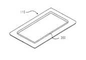
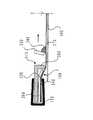
図1〜図7は本発明の一実施形態を示し、図1はスクリーン印刷装置の分解斜視図、図2はその断面図、図3はスクリーン印刷装置の組立斜視図、図4はその断面図、図5は孔版原紙組立体の平面図、図6はテンション付与枠の斜視図、図7は図4における実施形態の作用を表す断面図である。
【0011】
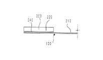
図1〜3において、100は孔版原紙組立体である。孔版原紙組立体100は、枠体200と孔版原紙210からなる。枠体200は略矩形状であり、外形を区画する外周辺と、略矩形状の開口を区画する内周辺とを備えている。孔版原紙210は、枠体200の外形に概ね等しい矩形状である。孔版原紙210は、枠体200の開口を覆って枠体200の一方の面に接着剤240により接着され、枠体200の開口に張られている。
【0012】
孔版原紙210は、インク通過性の支持体と、これに接着された感熱性の樹脂フィルムからなる。孔版原紙210の支持体が枠体に接着される。
【0013】
図中110は、上記孔版原紙組立体100に重ね合わせた状態で、孔版原紙210にテンションを付与するためのテンション付与枠である。
テンション付与枠110は略矩形状であり、その外形は枠体200の外形に略等しい。しかし、テンション付与枠110を孔版原紙組立体100に重ねた場合、テンション付与枠110の内周辺は枠体の内周辺よりも内側に突出する。そして、テンション付与枠110の内周辺には前記孔版原紙210に向けて隆起する隆起部300が形成されている。本例では、隆起部300は、テンション付与枠110と孔版原紙組立体100の各表面に対して垂直な方向に向けて突出しているが、これは必ずしも必須の条件ではない。要するに隆起部300は、テンション付与枠110の表面から突出する形状であればよい。また隆起部300の先端は、孔版原紙210に傷を与えないために曲面形状に形成されていることが好ましい。
【0014】
図4に示すように、テンション付与枠110は枠体200の他方の面に重ねる。隆起部300は枠体200の開口内に入り込み、孔版原紙210の周辺部を押し出してこれにテンションを与える。
【0015】
図中120は、重ね合わせた孔版原紙組立体100とテンション付与枠110の周縁を固定する固定手段としての挟持具である。この挟持具120は樹脂等のような、ある程度の弾性を有する材質からなる。その断面は図2に示すようにコの字型であり、その両フランジの先端の間隔は、孔版原紙組立体100とテンション付与枠110を重ね合わせた厚さよりも薄い。このため重ねた孔版原紙組立体100とテンション付与枠110を弾性力をもって保持することができる。また、図3に示すように、本例では4つの挟持具120が、重ねた孔版原紙組立体100とテンション付与枠110の4つの外周辺をそれぞれ固定している。
【0016】
なお、挟持具120は重ねた孔版原紙組立体100とテンション付与枠110を挟持して固定できるものであれば如何なる形状であっても良く、固定手段として不図示のクリップや粘着テープを使用しても良い。また、本例では重ねた孔版原紙組立体100とテンション付与枠110の4つの外周辺のみをそれぞれ固定したが、重ねた孔版原紙組立体100とテンション付与枠110の角部を含めて固定しても良い。
【0017】
次に、本実施の形態の作用について説明する。
まず、孔版原紙組立体100の孔版原紙210を製版する。次に、図1に示すように、孔版原紙組立体100の枠体200の他方の面、即ち孔版原紙210が接着されている一方の面とは反対側の面と、テンション付与枠110の隆起部300を対面させる。そして図3に示すように、孔版原紙組立体100とテンション付与枠110を重ね合わせ、両者を挟持具120により固定する。これで本例のスクリーン印刷装置が組み立てられた。
【0018】
次に、図4に示すように、上記のスクリーン印刷装置を被印刷体400に対して設置する。ここで、孔版原紙組立体100の孔版原紙210が被印刷体400の印刷面に対峙している。即ち、孔版原紙210の樹脂フィルムが被印刷体400の印刷面に対峙している。そして、孔版原紙210が被印刷体400に接している面と反対側の面、即ち支持体の上面にインク260を載せる。スキージ250で孔版原紙210を加圧しながら孔版原紙210を被印刷体400に接着させて矢印方向にスキージングする。インク260は、孔版原紙210の穿孔部分を通過して被印刷体400に転移し、印刷画像を形成する。
【0019】
ここで、上記のような実施形態の場合、図7に示すように、接着剤240で接着された孔版原紙210と枠体200が剥がれ、孔版原紙210に適度なテンションを付与できない不都合が発生することも考えられる。
【0020】
このような可能性を排除するためのさらに好ましい他の実施形態を、図8〜図16を用いて説明する。
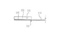
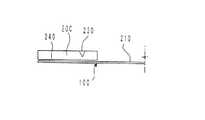
図8は孔版原紙組立体の他の実施形態をスクリーン印刷装置に使用した場合の断面図、図9は孔版原紙組立体の他の実施形態を表す平面図、図10〜図12は孔版原紙組立体の折曲用溝部の実施例を表す断面図、図13は孔版原紙組立体の折曲用溝部の実施例を表す平面図、図14はその断面図、図15及び図16は孔版原紙組立体の切込部の実施例を表す平面図である。
【0021】
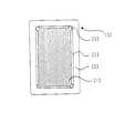
図8及び図9に示すように、孔版原紙組立体100の枠体200には、孔版原紙210が接着されている一方の面と反対側の他方の面に、折曲用溝部220が形成されている。折曲用溝部220は、枠体200の外周辺と内周辺に対して平行であり、枠体200の開口を取り巻いて形成されている。
【0022】
また、折曲用溝部220の構造の一例を図10、11、図12に示す。これらは、枠体200を厚さ方向に貫通しないハーフカット又は型押しによる溝である。
【0023】
折曲用溝部220は次のような機能を満たす構造であることが要求される。まず、孔版原紙組立体100を組み立てた時、折曲用溝部220を境界に枠体200が容易に折り曲げられることが必要である。次に、孔版原紙組立体100を組み立てて枠体200が折れ曲がった状態で、枠体200が孔版原紙210に引っ張られて折曲用溝部220で破損しないことが必要である。即ち、枠体200の折曲用溝部220は、孔版原紙組立体100の中心からの放射線方向について十分な引っ張り強度を有する必要がある。このような条件を満たす構造であれば、前述した構造以外の如何なる構造であっても良い。
【0024】
なお、前記の条件下において、折曲用溝部220は連続的な溝でなく、図13に示すミシン目のような構造で形成されていても良い。また、図13の断面D−Dを表す図14に示すように、ミシン目のような断続的な折曲用溝部220に限り、ハーフカットではなく、枠体200を貫通しても良い。
【0025】
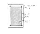
次に、図15及び図16に示すように、孔版原紙組立体100の枠体200の内周辺の四隅に、切込部230を設けても良い。このように切込部230を設ければ、孔版原紙組立体100とテンション付与枠110を組み立てる際に枠体200を折曲用溝部220で折り曲げる力が小さくて済み、且つ、枠体200及び孔版原紙210に対するダメージが少なくなる。また、切込部230の切り込み長さは、略垂直に交わる隣接する折曲用溝部220の交点までの距離を必要とする。なお、切込部230は如何なる形状であっても良い。
【0026】
【発明の効果】
本発明のスクリーン印刷装置によれば、孔版原紙組立体にテンション付与枠を挟持具で固定するだけの簡単な構造で、孔版原紙に適度なテンションを付与することができる。このため、確実且つ容易に印刷を行うことができる。また、孔版原紙組立体の枠体に折曲用溝部を設ければ、テンション付与枠によって孔版原紙にテンションを付与した時に、孔版原紙組立体を構成する孔版原紙と枠体の剥がれ等による破損を防止でき、孔版原紙に常に適度で安定したテンションを付与することができる。
【図面の簡単な説明】
【図1】本発明のスクリーン印刷装置の実施例を分解して示す斜視図である。
【図2】図1記載の断面A−Aを示す断面図である。
【図3】本発明のスクリーン印刷装置の実施例を示す斜視図である。
【図4】図3の切断線B−Bにおける断面図である。
【図5】本発明の孔版原紙組立体の実施例を示す平面図である。
【図6】本発明のテンション付与枠の実施例を示した斜視図である。
【図7】図3の切断線B−Bにおける断面図である。
【図8】図7と比較した孔版原紙組立体の他の実施形態を本願のスクリーン印刷装置に使用した場合の断面図である。
【図9】本発明における孔版原紙組立体の他の実施形態を示す平面図である。
【図10】図9の切断線C−Cにおける折曲用溝部の実施例を示す断面図である。
【図11】図9の切断線C−Cにおける折曲用溝部の実施例を示す断面図である。
【図12】図9の切断線C−Cにおける折曲用溝部の実施例を示す断面図である。
【図13】本発明における孔版原紙組立体の他の実施形態を示す平面図である。
【図14】図10の切断線D−Dにおける折曲用溝部の実施例を示す断面図である。
【図15】本発明における孔版原紙組立体の切り込み部の実施例を示す平面図である。
【図16】本発明における孔版原紙組立体の切り込み部の実施例を示す平面図である。
【符号の説明】
100 孔版原紙組立体
110 テンション付与枠
120 挟持具
200 枠体
210 孔版原紙
220 折曲用溝部
230 切込部
240 接着剤
250 スキージ
260 インク
300 隆起部
400 被印刷体[0001]
BACKGROUND OF THE INVENTION
The present invention relates to a screen printing apparatus and a stencil sheet assembly used for squeegee printing.
[0002]
[Prior art]
As shown in Japanese Patent Publication No. 6-21733, a conventional simple printing apparatus used for squeegee printing is provided on a base so that the distance between the base on which the printing medium is placed and the base can be adjusted. And an attached plate frame. A stencil sheet assembly in which a stencil sheet is stretched around the frame is detachably attached to the plate frame. In printing, a printing medium is placed at a predetermined position on the substrate, ink is placed on the stencil sheet, and the stencil sheet is pushed down to squeegee. As a result, an appropriate tension is applied to the stencil sheet, and the stencil sheet to which the tension is applied comes into contact with the substrate, and the ink is transferred to the substrate to form an image.
[0003]
[Problems to be solved by the invention]
In the case of the above-described structure, the tension applied to the stencil sheet by squeezing does not become constant as the number of uses is repeated, and a skilled technique is necessary to stably apply an appropriate tension. Moreover, the apparatus was large-scale and the structure was complicated.
[0004]
Further, when tension is applied to the stencil sheet of the stencil sheet assembly, the tension applied may become unstable due to damage due to peeling of the adhesive bonding the stencil sheet and the frame.
[0005]
An object of the present invention is to provide a screen printing apparatus and a stencil sheet assembly that can reliably apply a certain tension to the stencil sheet with a simple structure.
[0006]
[Means for Solving the Problems]
The screen printing apparatus according to
[0008]
The stencil sheet assembly described in claim2 includes a frame (200) having an outer periphery that defines an outer shape and an inner periphery that defines an opening, and one surface of the frame so as to cover the opening. And a stencil sheet (210) bonded to the frame, and at least one folding groove (220) formed on the other surface of the frame and parallel to the inner periphery of the frame.
[0009]
Stencil sheet assembly according to claim3, in the stencil sheet assembly of claim2, wherein said frame body (200), four outer peripheral four inner peripheral and substantially rectangular opening A substantially rectangular frame body, wherein the folding groove portion (220) comprises four folding groove portions formed along the four inner peripheries, and the inner periphery of the frame body In the four corners, cut portions (230) reaching the intersections of the bending groove portions adjacent to each other that intersect perpendicularly are formed.
[0010]
DETAILED DESCRIPTION OF THE INVENTION
Hereinafter, an embodiment of the present invention will be described with reference to the drawings.
1 to 7 show an embodiment of the present invention, FIG. 1 is an exploded perspective view of a screen printing apparatus, FIG. 2 is a sectional view thereof, FIG. 3 is an assembled perspective view of the screen printing apparatus, and FIG. 5 is a plan view of the stencil sheet assembly, FIG. 6 is a perspective view of a tension applying frame, and FIG. 7 is a cross-sectional view showing the operation of the embodiment in FIG.
[0011]
1-3, 100 is a stencil sheet assembly. The
[0012]
The
[0013]
In the drawing,
The
[0014]
As shown in FIG. 4, the
[0015]
In the figure,
[0016]
The
[0017]
Next, the operation of the present embodiment will be described.
First, the
[0018]
Next, as shown in FIG. 4, the screen printing apparatus is installed on the
[0019]
Here, in the case of the embodiment as described above, as shown in FIG. 7, the
[0020]
Still another preferred embodiment for eliminating such a possibility will be described with reference to FIGS.
8 is a cross-sectional view of another embodiment of the stencil sheet assembly used in a screen printing apparatus, FIG. 9 is a plan view showing another embodiment of the stencil sheet assembly, and FIGS. 10 to 12 are stencil sheet sets. FIG. 13 is a plan view showing an embodiment of the folding groove portion of the stencil sheet assembly, FIG. 14 is a sectional view thereof, and FIGS. 15 and 16 are stencil sheet sets. It is a top view showing the Example of the solid cut | notch part.
[0021]
As shown in FIGS. 8 and 9, the
[0022]
An example of the structure of the bending
[0023]
The bending
[0024]
Note that, under the above-described conditions, the
[0025]
Next, as shown in FIGS. 15 and 16,
[0026]
【The invention's effect】
According to the screen printing apparatus of the present invention, an appropriate tension can be applied to the stencil sheet with a simple structure in which the tension applying frame is fixed to the stencil sheet assembly with a clamping tool. For this reason, printing can be performed reliably and easily. In addition, if a bending groove is provided in the frame of the stencil sheet assembly, when the tension is applied to the stencil sheet by the tension applying frame, the stencil sheet and the frame constituting the stencil sheet assembly may be damaged due to peeling. It is possible to prevent the stencil sheet from being applied with a moderate and stable tension.
[Brief description of the drawings]
FIG. 1 is an exploded perspective view showing an embodiment of a screen printing apparatus of the present invention.
FIG. 2 is a cross-sectional view showing a cross-section AA shown in FIG.
FIG. 3 is a perspective view showing an embodiment of the screen printing apparatus of the present invention.
4 is a cross-sectional view taken along a cutting line BB in FIG. 3. FIG.
FIG. 5 is a plan view showing an embodiment of the stencil sheet assembly of the present invention.
FIG. 6 is a perspective view showing an embodiment of a tension applying frame of the present invention.
7 is a cross-sectional view taken along a cutting line BB in FIG. 3. FIG.
FIG. 8 is a cross-sectional view of another embodiment of the stencil sheet assembly compared with FIG. 7 when used in the screen printing apparatus of the present application.
FIG. 9 is a plan view showing another embodiment of the stencil sheet assembly according to the present invention.
10 is a cross-sectional view illustrating an example of a bending groove portion taken along a cutting line CC in FIG. 9;
11 is a cross-sectional view showing an example of a bending groove portion taken along a cutting line CC in FIG. 9;
12 is a cross-sectional view illustrating an example of a bending groove portion taken along a cutting line CC in FIG. 9;
FIG. 13 is a plan view showing another embodiment of the stencil sheet assembly according to the present invention.
14 is a cross-sectional view showing an example of a bending groove portion taken along a cutting line DD in FIG.
FIG. 15 is a plan view showing an embodiment of a cut portion of a stencil sheet assembly according to the present invention.
FIG. 16 is a plan view showing an embodiment of a cut portion of a stencil sheet assembly according to the present invention.
[Explanation of symbols]
DESCRIPTION OF
Claims (3)
Translated fromJapanese前記枠体の内周辺よりも内側に突出するとともに前記孔版原紙に向けて隆起する隆起部を有し、前記枠体の他方の面に配置されて前記孔版原紙にテンションを与えるテンション付与枠と、
前記テンション付与枠の前記隆起部が隆起している方向の前面と前記枠体の他方の面が接するように重ね合わせた前記テンション付与枠と前記孔版原紙組立体を固定する固定手段と、を備えたスクリーン印刷装置において、
前記枠体の他方の面に、前記枠体の内周辺と平行な少なくとも1本の折曲用溝部が形成されていることを特徴とするスクリーン印刷装置。A stencil sheet assembly comprising a frame having an outer periphery for defining an outer shape and an inner periphery for defining an opening; and a stencil sheet bonded to one surface of the frame so as to cover the opening;
A tension-applying frame that protrudes inward from the inner periphery of the frame and protrudes toward the stencil sheet, and is disposed on the other surface of the frame to apply tension to the stencil sheet;
A fixing means for fixing the tension applying frame and the stencil sheet assembly so that the front surface in the direction in which the raised portion of the tension applying frame is raised and the other surface of the frame are in contact with each other;in the screen printingapparatus,
A screen printing apparatus, wherein at least one folding groove portion parallel to the inner periphery of the frame body is formed on the other surface of the frame body.
前記開口を覆うように前記枠体の一方の面に接着された孔版原紙と、
前記枠体の他方の面に形成され、前記枠体の内周辺と平行な少なくとも1本の折曲用溝部と、
を有する孔版原紙組立体。A frame having an outer periphery that defines an outer shape and an inner periphery that defines an opening;
A stencil sheet bonded to one surface of the frame so as to cover the opening;
Formed on the other surface of the frame and at least one folding groove parallel to the inner periphery of the frame;
A stencil sheet assembly comprising:
前記枠体は、4つの外周辺と4つの内周辺と実質的に矩形の開口とを有する実質的に矩形状の枠体であり、
前記折曲用溝部は、前記4つの内周辺に沿って形成された4本の折曲用溝部からなり、
前記枠体の内周辺の四隅には、垂直に交わる互いに隣接した前記折曲用溝部の交点に達する切込部が形成されている孔版原紙組立体。In the stencil sheet assembly according to claim2 ,
The frame is a substantially rectangular frame having four outer perimeters, four inner perimeters and a substantially rectangular opening;
The bending groove portion is composed of four bending groove portions formed along the four inner peripheries.
A stencil sheet assembly in which notches are formed at four corners on the inner periphery of the frame to reach intersections of the bending grooves adjacent to each other perpendicularly to each other.
Priority Applications (3)
| Application Number | Priority Date | Filing Date | Title |
|---|---|---|---|
| JP34224199AJP3639482B2 (en) | 1999-12-01 | 1999-12-01 | Screen printing apparatus and stencil sheet assembly |
| US09/725,901US6446550B2 (en) | 1999-12-01 | 2000-11-30 | Screen printing machine and stencil sheet assembly |
| US10/173,313US6698349B2 (en) | 1999-12-01 | 2002-06-18 | Screen printing machine |
Applications Claiming Priority (1)
| Application Number | Priority Date | Filing Date | Title |
|---|---|---|---|
| JP34224199AJP3639482B2 (en) | 1999-12-01 | 1999-12-01 | Screen printing apparatus and stencil sheet assembly |
Publications (2)
| Publication Number | Publication Date |
|---|---|
| JP2001150632A JP2001150632A (en) | 2001-06-05 |
| JP3639482B2true JP3639482B2 (en) | 2005-04-20 |
Family
ID=18352209
Family Applications (1)
| Application Number | Title | Priority Date | Filing Date |
|---|---|---|---|
| JP34224199AExpired - Fee RelatedJP3639482B2 (en) | 1999-12-01 | 1999-12-01 | Screen printing apparatus and stencil sheet assembly |
Country Status (2)
| Country | Link |
|---|---|
| US (2) | US6446550B2 (en) |
| JP (1) | JP3639482B2 (en) |
Families Citing this family (24)
| Publication number | Priority date | Publication date | Assignee | Title |
|---|---|---|---|---|
| JP3639482B2 (en)* | 1999-12-01 | 2005-04-20 | 理想科学工業株式会社 | Screen printing apparatus and stencil sheet assembly |
| TR201710711T4 (en) | 2002-05-02 | 2018-03-21 | Asm Assembly Systems Weymouth Ltd | Screen printing unit. |
| US20070205969A1 (en) | 2005-02-23 | 2007-09-06 | Pixtronix, Incorporated | Direct-view MEMS display devices and methods for generating images thereon |
| US8519945B2 (en) | 2006-01-06 | 2013-08-27 | Pixtronix, Inc. | Circuits for controlling display apparatus |
| US9261694B2 (en) | 2005-02-23 | 2016-02-16 | Pixtronix, Inc. | Display apparatus and methods for manufacture thereof |
| US9158106B2 (en) | 2005-02-23 | 2015-10-13 | Pixtronix, Inc. | Display methods and apparatus |
| US8159428B2 (en) | 2005-02-23 | 2012-04-17 | Pixtronix, Inc. | Display methods and apparatus |
| US9087486B2 (en) | 2005-02-23 | 2015-07-21 | Pixtronix, Inc. | Circuits for controlling display apparatus |
| US7999994B2 (en) | 2005-02-23 | 2011-08-16 | Pixtronix, Inc. | Display apparatus and methods for manufacture thereof |
| US9229222B2 (en) | 2005-02-23 | 2016-01-05 | Pixtronix, Inc. | Alignment methods in fluid-filled MEMS displays |
| US9082353B2 (en) | 2010-01-05 | 2015-07-14 | Pixtronix, Inc. | Circuits for controlling display apparatus |
| US8482496B2 (en) | 2006-01-06 | 2013-07-09 | Pixtronix, Inc. | Circuits for controlling MEMS display apparatus on a transparent substrate |
| US8310442B2 (en) | 2005-02-23 | 2012-11-13 | Pixtronix, Inc. | Circuits for controlling display apparatus |
| GB2435011B (en)* | 2006-02-08 | 2010-06-02 | Dek Int Gmbh | Printing screens, frames therefor and printing screen units |
| US8526096B2 (en) | 2006-02-23 | 2013-09-03 | Pixtronix, Inc. | Mechanical light modulators with stressed beams |
| US9176318B2 (en)* | 2007-05-18 | 2015-11-03 | Pixtronix, Inc. | Methods for manufacturing fluid-filled MEMS displays |
| US8169679B2 (en) | 2008-10-27 | 2012-05-01 | Pixtronix, Inc. | MEMS anchors |
| US20110205259A1 (en)* | 2008-10-28 | 2011-08-25 | Pixtronix, Inc. | System and method for selecting display modes |
| EP2529931A4 (en)* | 2010-01-29 | 2014-06-18 | Furetsu Kasuya | SCREEN STRETCH FRAME |
| KR20120132680A (en) | 2010-02-02 | 2012-12-07 | 픽스트로닉스 인코포레이티드 | Methods for manufacturing cold seal fluid-filled display apparatus |
| WO2013014781A1 (en)* | 2011-07-28 | 2013-01-31 | 株式会社メイコー | Screen printing plate |
| US9134552B2 (en) | 2013-03-13 | 2015-09-15 | Pixtronix, Inc. | Display apparatus with narrow gap electrostatic actuators |
| US9351406B2 (en) | 2013-12-17 | 2016-05-24 | QTS Engineering, Inc. | Stencil foil assembly |
| WO2015192128A1 (en)* | 2014-06-13 | 2015-12-17 | Domesticated Partners, Llc | Device, method, and kit for applying stencil patterns to a fabric and fabric-like material |
Family Cites Families (8)
| Publication number | Priority date | Publication date | Assignee | Title |
|---|---|---|---|---|
| US4981075A (en)* | 1989-03-29 | 1991-01-01 | Xpres Corporation | Sheet stretching holding frame |
| JPH0852855A (en) | 1994-08-15 | 1996-02-27 | Seiwa Kogyo Kk | Screen frame |
| GB2303333B (en)* | 1995-07-20 | 1998-09-23 | David Godfrey Williams | Improved apparatus for supporting and tensioning a stencil or mask for use in applying solder paste to circuit boards and a mounting support means therefor |
| US6609652B2 (en)* | 1997-05-27 | 2003-08-26 | Spheretek, Llc | Ball bumping substrates, particuarly wafers |
| US6331223B1 (en)* | 1997-12-24 | 2001-12-18 | Saint-Gobain Bayform America, Inc. | Method of fabricating adhesively secured frame assembly |
| JPH11291600A (en)* | 1998-04-13 | 1999-10-26 | Riso Kagaku Corp | Decompression printing device |
| JPH11350329A (en)* | 1998-06-10 | 1999-12-21 | Brother Ind Ltd | Embroidery frame |
| JP3639482B2 (en)* | 1999-12-01 | 2005-04-20 | 理想科学工業株式会社 | Screen printing apparatus and stencil sheet assembly |
- 1999
- 1999-12-01JPJP34224199Apatent/JP3639482B2/ennot_activeExpired - Fee Related
- 2000
- 2000-11-30USUS09/725,901patent/US6446550B2/ennot_activeExpired - Fee Related
- 2002
- 2002-06-18USUS10/173,313patent/US6698349B2/ennot_activeExpired - Lifetime
Also Published As
| Publication number | Publication date |
|---|---|
| US6446550B2 (en) | 2002-09-10 |
| JP2001150632A (en) | 2001-06-05 |
| US6698349B2 (en) | 2004-03-02 |
| US20030230204A1 (en) | 2003-12-18 |
| US20010002575A1 (en) | 2001-06-07 |
Similar Documents
| Publication | Publication Date | Title |
|---|---|---|
| JP3639482B2 (en) | Screen printing apparatus and stencil sheet assembly | |
| CN100519185C (en) | Printing screen, frame therefor and printing screen unit | |
| JP3431667B2 (en) | Metal mask for cream solder and mounting method to frame | |
| JP2018176490A (en) | Screen printing plate and method for producing screen printing plate | |
| JP2947332B2 (en) | Stamping equipment | |
| US5054391A (en) | Thermal stencil sheet assembly with stencil sheet temporarily detachable from frame | |
| CN101544095B (en) | Printing screen, its frame and printing screen device | |
| JPS62156982A (en) | A stencil stamp and a method for manufacturing a stencil stamp | |
| JPS60180891A (en) | Heat-sensitive stencil paper | |
| JP3508052B2 (en) | File creation kit | |
| JP3010172U (en) | Printing paper | |
| EP0742105B1 (en) | Assembly stencil stamp and method for preparation thereof | |
| JP2586247Y2 (en) | Paper connection tape | |
| JPH0732086Y2 (en) | Combination of thermal stencil sheet with frame and edge forming device | |
| JPH09314970A (en) | Stamp assembly kit and ink impregnator for stamp | |
| JP2001287487A (en) | Clip made of synthetic resin | |
| JP4683777B2 (en) | Sheet | |
| JP2000052631A (en) | Stencil assembly for stencil printing | |
| JPH09281494A (en) | Printing plate for orienting film | |
| JPS63319194A (en) | Stencil printing base paper | |
| JPS5968953U (en) | Printing paper holding base sheet | |
| JPS63116893A (en) | Screen plate for printing | |
| JPS62220377A (en) | Stamp | |
| JPH0740695A (en) | Clip | |
| JPH06781U (en) | Card printing support sheet |
Legal Events
| Date | Code | Title | Description |
|---|---|---|---|
| A977 | Report on retrieval | Free format text:JAPANESE INTERMEDIATE CODE: A971007 Effective date:20040304 | |
| A131 | Notification of reasons for refusal | Free format text:JAPANESE INTERMEDIATE CODE: A131 Effective date:20040323 | |
| A521 | Request for written amendment filed | Free format text:JAPANESE INTERMEDIATE CODE: A523 Effective date:20040518 | |
| TRDD | Decision of grant or rejection written | ||
| A01 | Written decision to grant a patent or to grant a registration (utility model) | Free format text:JAPANESE INTERMEDIATE CODE: A01 Effective date:20050111 | |
| A61 | First payment of annual fees (during grant procedure) | Free format text:JAPANESE INTERMEDIATE CODE: A61 Effective date:20050114 | |
| R150 | Certificate of patent or registration of utility model | Free format text:JAPANESE INTERMEDIATE CODE: R150 | |
| FPAY | Renewal fee payment (event date is renewal date of database) | Free format text:PAYMENT UNTIL: 20090121 Year of fee payment:4 | |
| FPAY | Renewal fee payment (event date is renewal date of database) | Free format text:PAYMENT UNTIL: 20090121 Year of fee payment:4 | |
| FPAY | Renewal fee payment (event date is renewal date of database) | Free format text:PAYMENT UNTIL: 20100121 Year of fee payment:5 | |
| FPAY | Renewal fee payment (event date is renewal date of database) | Free format text:PAYMENT UNTIL: 20110121 Year of fee payment:6 | |
| FPAY | Renewal fee payment (event date is renewal date of database) | Free format text:PAYMENT UNTIL: 20110121 Year of fee payment:6 | |
| FPAY | Renewal fee payment (event date is renewal date of database) | Free format text:PAYMENT UNTIL: 20120121 Year of fee payment:7 | |
| FPAY | Renewal fee payment (event date is renewal date of database) | Free format text:PAYMENT UNTIL: 20120121 Year of fee payment:7 | |
| FPAY | Renewal fee payment (event date is renewal date of database) | Free format text:PAYMENT UNTIL: 20130121 Year of fee payment:8 | |
| FPAY | Renewal fee payment (event date is renewal date of database) | Free format text:PAYMENT UNTIL: 20130121 Year of fee payment:8 | |
| FPAY | Renewal fee payment (event date is renewal date of database) | Free format text:PAYMENT UNTIL: 20140121 Year of fee payment:9 | |
| R250 | Receipt of annual fees | Free format text:JAPANESE INTERMEDIATE CODE: R250 | |
| R250 | Receipt of annual fees | Free format text:JAPANESE INTERMEDIATE CODE: R250 | |
| R250 | Receipt of annual fees | Free format text:JAPANESE INTERMEDIATE CODE: R250 | |
| LAPS | Cancellation because of no payment of annual fees |