JP3638010B2 - Method and apparatus for treating odorous gas generated from composting facilities - Google Patents
Method and apparatus for treating odorous gas generated from composting facilitiesDownload PDFInfo
- Publication number
- JP3638010B2 JP3638010B2JP2000349444AJP2000349444AJP3638010B2JP 3638010 B2JP3638010 B2JP 3638010B2JP 2000349444 AJP2000349444 AJP 2000349444AJP 2000349444 AJP2000349444 AJP 2000349444AJP 3638010 B2JP3638010 B2JP 3638010B2
- Authority
- JP
- Japan
- Prior art keywords
- deodorizing
- water
- biological
- biological deodorization
- generated
- Prior art date
- Legal status (The legal status is an assumption and is not a legal conclusion. Google has not performed a legal analysis and makes no representation as to the accuracy of the status listed.)
- Expired - Fee Related
Links
Images


Classifications
- Y—GENERAL TAGGING OF NEW TECHNOLOGICAL DEVELOPMENTS; GENERAL TAGGING OF CROSS-SECTIONAL TECHNOLOGIES SPANNING OVER SEVERAL SECTIONS OF THE IPC; TECHNICAL SUBJECTS COVERED BY FORMER USPC CROSS-REFERENCE ART COLLECTIONS [XRACs] AND DIGESTS
- Y02—TECHNOLOGIES OR APPLICATIONS FOR MITIGATION OR ADAPTATION AGAINST CLIMATE CHANGE
- Y02A—TECHNOLOGIES FOR ADAPTATION TO CLIMATE CHANGE
- Y02A50/00—TECHNOLOGIES FOR ADAPTATION TO CLIMATE CHANGE in human health protection, e.g. against extreme weather
- Y02A50/20—Air quality improvement or preservation, e.g. vehicle emission control or emission reduction by using catalytic converters
- Y—GENERAL TAGGING OF NEW TECHNOLOGICAL DEVELOPMENTS; GENERAL TAGGING OF CROSS-SECTIONAL TECHNOLOGIES SPANNING OVER SEVERAL SECTIONS OF THE IPC; TECHNICAL SUBJECTS COVERED BY FORMER USPC CROSS-REFERENCE ART COLLECTIONS [XRACs] AND DIGESTS
- Y02—TECHNOLOGIES OR APPLICATIONS FOR MITIGATION OR ADAPTATION AGAINST CLIMATE CHANGE
- Y02W—CLIMATE CHANGE MITIGATION TECHNOLOGIES RELATED TO WASTEWATER TREATMENT OR WASTE MANAGEMENT
- Y02W30/00—Technologies for solid waste management
- Y02W30/40—Bio-organic fraction processing; Production of fertilisers from the organic fraction of waste or refuse
Landscapes
- Treating Waste Gases (AREA)
- Fertilizers (AREA)
Description
Translated fromJapanese【0001】
【発明の属する技術分野】
本発明は、堆肥化施設から発生する臭気ガスの処理に係り、特に、生ごみ、汚泥、畜糞及び食品廃棄物などの各種有機性廃棄物の発酵処理に当たり、堆肥化施設などから発生する臭気を含んだ排ガスを生物脱臭装置で処理する臭気ガスの処理方法と装置に関する。
【0002】
【従来の技術】
従来の堆肥化施設においては、牛、豚、鶏糞などの畜糞、下水汚泥、集落排水汚泥、コミプラ汚泥、食品工場汚泥などの各種汚泥、混合収集ごみ、分別収集生ごみなどのごみ、剪定枝、斃死魚、魚腸骨などの水産廃棄物、収穫後の植物残渣、籾殻、稲わら、バーク、木屑、おがくずなどの農林廃棄物などの有機性廃棄物を、好気性あるいは嫌気性発酵により処理してきた。
それらの原料は大部分、腐敗性の原料であるため、堆肥化施設へ搬入された後、発酵槽へ投入して好気性発酵を行わせ堆肥としてきた。
原料の段階においては、搬入時にすでに原料の一部の腐敗により硫黄系の硫化水素、メチルメルカプタンなどが発生する。また、主たる臭気である窒素系のアンモニアは、発酵槽での好気性発酵の過程における有機物の分解時に多量に発生する。
堆肥化施設においては、これらの臭気により、周囲の住民への臭気公害を及ぼさないように対策を行っている。
【0003】
図4に、堆肥化施設の脱臭フローを示す。
堆肥化原料は、原料置場1に一次貯留された後、ショベルローダにより発酵槽4へ投入される。発酵槽4では、パドル式撹拌装置などの切返し機7による原料の切返しと、発酵槽通気ファン8による通気を受け、原料を好気性発酵させ約14日程度で一次発酵堆肥となる。
堆肥化施設では、原料や発酵時に臭気が発生する。
そこで、原料受入部や原料置場1を原料受入建屋2内に収納したり.ビニールシートで原料置場1を覆い、かつ原料受入建屋2の上部から原料置場の空気を前処理脱臭ファン3で吸引する。特に、アンモニアなどが最も発生する発酵槽4では、発酵槽全体をビニールシートや発酵槽建屋5で覆い、かつ発酵槽4内の空気を脱臭ファン6で吸引することで、発酵槽内を負圧として外部への臭気の拡散を防いでいる。
【0004】
上記の臭気対策を行う場合、発酵槽4内から脱臭ファン6により吸引された空気、すなわち排ガスは、その後、ダクト9により脱臭装置10へ導かれ、脱臭された後、排ガスは大気へ開放される。
各種臭気の脱臭方式としては、水洗浄、薬液洗浄、活性炭、オゾン、燃焼、生物脱臭方式などがある。
堆肥化施設からの排ガスの脱臭装置の方式としては、発酵過程において発生して堆肥化施設から吸引される排ガスの性状から、上記の方式のうち、大部分の施設で生物脱臭方式が採用されてきた。
すなわち、吸引される排ガスの臭気成分として、堆肥化される原料である有機性廃棄物の種類や発酵処理方法で多少の変動はあるが、原料中から発生する臭気成分としては、腐敗により生じた硫黄系の硫化水素、メチルメルカプタンなどが、0.01〜0.1ppm程度含まれ、また、臭気成分のほとんどを占める好気性発酵過程で発生する窒素系のアンモニアは、100〜500ppm含まれている。
また、排ガスの性状として、有機性廃棄物の発酵により温度が上昇し、かつ水蒸気の蒸発により、温度は20〜40℃、相対湿度は80〜100%である。
【0005】
従来、これらの排ガスを処理する脱臭方法としては、アンモニア濃度が高い、相対湿度が高い、運転経費がほとんどかからないなどの理由から生物脱臭装置が使用されてきた。また、生物脱臭装置の充填材として、土壌を採用するのがほとんどであり、そのため堆肥化施設の生物脱臭装置といえば、土壌脱臭装置を示す程、普通に採用されている。
図5に、土壌脱臭装置の断面図を示す。
土壌脱臭装置11では、各種の臭気成分を、土壌中に無限に生息するアンモニアなどの窒素系臭気成分を分解するニトロソモナス、ニトロバクターなどの硝化菌、硫黄系の硫化水素などの臭気を分解するチオパチルスなどの脱臭用微生物により、各種臭気成分を分解している。
土壌中には、上記以外にも数多くの種類と数の脱臭用微生物が生息しているが、その脱臭用微生物の生息環境を常に適切に維持しておかないと、その機能は発揮できない。すなわち、均一な好気的雰囲気、有機物の供給、水分の保持である。
【0006】
しかし、土壌脱臭装置11では、土壌脱臭装置11を建設した当初は、土壌12の層厚が50〜100cmのものが、次第に自重と降雨により圧密、締まってくる。その結果、土壌層内の通気抵抗が全体として増加すると同時に、土壌12の平面状の位置により不均衡が発生し、その結果、通気し易い箇所、すなわち通気抵抗が小さい箇所から、集中的に排ガスが上部へ向かって通過することとなる。そのため、土壌脱臭装置11では、数か月経過すると土壌脱臭装置11の壁面13の壁面部12Aや末端部12Bなど通気抵抗が小さい部分から排ガスの吹き抜けが生じ、その結果、土壌脱臭装置11の底面部14から十分脱臭されなかった悪臭を含んだ排ガスが、表面に出てくる結果、臭気が発生することとなった。
特に、降雨後には、土壌12の上に降った雨が、すぐに底面部14へ浸透しないため、土壌層へ降雨が滞留し、土壌層の圧力損失が急に上昇する。その結果、排ガスの吹き抜けが大きくなり、脱臭されない生の排ガスが、土壌層のあちこちに発生した水たまり12Cから泡のようになって出てくる。
そのため、降雨時には通常よりひどい臭気が、周囲へただようこととなった。
【0007】
図6に、改良された土壌脱臭装置の断面を示す。
上記を改善するため、従来、土壌12として、脱臭用微生物が多量に生息するために使用されていた黒ぼく土に加え、通気性の改善と脱臭用微生物の生息環境を維持するため、多孔質の火山レキを黒ぼく土と混合したものを採用している場合もある。
また、排ガスの吹き抜けを防止するため、土壌脱臭装置11全体へ均一に空気が流れるように、送気ダクト9の途中にダンパ15を設置し、それにより土壌脱臭装置の全面から均一に空気が流れるようにした。ダンパ15は、メイン9Aのダクトから分岐した副ダクト9Bの途中に設置して、各々の土壌層への風量を調整できる方式が採用されている。また、メインダクト9Aにダンパを設け、その調整により副ダクト9Bへの風量を調整する方法もある。
また、土壌層へ均一に排ガスが流れるように、土壌12層の下に砂利層12’を設ける方法も採用されている。
【0008】
加えて、土壌脱臭装置11の壁面13からの排ガスの吹き抜け防止用に、壁面部12Aの床面部の端から50cm程度は、不浸透性の通気性が少ない粘土質土壌16で囲み、その内側に土壌12層を充填している。
しかし、このような対策を採用して運転した場合であっても、土壌を採用している限りは、その粒径、通気性、保水性を抜本的に改善することは難しい。そのため、土壌脱臭装置11では、数か月に1回の土壌の耕運や天地返しなど、土壌層の圧力損失を減らし、均一圧力損失にする作業が必須であった。
そのため、最近、生物脱臭装置の充填材の材料として、圧力損失の低減、経年変化による圧力損失の増加防止、脱臭性能の向上の3点から、新規の脱臭材が色々採用され始めた。
これらの脱臭材として、有機質では、バーク、コンポスト、無機質の脱臭材では、ゼオライト、セラミックス、ロックウールなどが使用されている。
【0009】
これらの脱臭材のうち、有機質の脱臭材は、見掛比重が小さい、圧力損失は小さい、入手が容易などの長所を持っているが、脱臭材として使用する場合、経年変化と共に次第に有機質脱臭材が分解により少なくなり、かつそれらの分解により細粒化し通気抵抗が増加するため、1〜3年程度で有機質脱臭材の交換が必要となり、その手間がかかることが難点である。
ただし、交換した有機質脱臭材は、再度堆肥の原料として使用することができるので、堆肥化施設においては、水分調整材や原料としてバークの使用は、生産された堆肥の一次的な利用先として、循環使用できるので資源の有効利用としては捨てがたい。
無機質の脱臭材であるゼオライト、セラミックス、ロックウールは、いずれも脱臭用微生物が生息し易い多孔質の物質である。
特に、ゼオライトは、それ自体物理吸着作用があり、また多孔質のため最近脚光を浴びてきた脱臭材である。
【0010】
また、これら無機質の脱臭材は、有機質脱臭材と比較すると、それ自体はほとんど分解、変質しないため永続的に使用できる材料である。
これらは、自然の山から産出したゼオライトや人工的に生産したセラミックス、ロックウールに分けられる。
しかし、これらの脱臭材は、それ自体が製品として他の用途に多量に使用されているため、従来の土壌や有機質脱臭材と比較するとコストがかなり高い。
しかし、これらは、土壌と比較すると通気性が良好なため、堆積高さは、土壌の場合に採用されている50〜100cmと比較し、200〜250cm程度堆積できる。
それにより、ゼオライト、ロックウールを使用した生物脱臭装置では、土壌脱臭装置での設置面積と比較すると、面積比で1/2.5〜1/5でよく、その結果、建設コストを概略2〜3割低減できる。
【0011】
よって、近年、堆肥化施設において敷地面積が狭い場所にも設置できることと、建設費が安くできることからゼオライト、ロックウールを使用した生物脱臭装置が増加している。
特に、それらの無機質脱臭材の中でも、ゼオライトが取り扱い、脱臭性能から急速にその採用が高まってきている。
しかし、ゼオライトは生産場所が限られることと、概略10t/dの堆肥化施設では、生物脱臭面積が100m2程度となり、使用するゼオライトの容量が200m3と多量必要となるため、短期間に所定のゼオライトの入手が困難でかつ、建設場所によっては、ゼオライトの輸送コストが高く、ゼオライトに代わる高性能で安価な脱臭材が求められていた。
【0012】
次に、生物脱臭システムについての経緯及び問題点を示す。
図7に、従来の生物脱臭システムのフローを示す。
この生物脱臭システムでは、脱臭材12として黒ぼく土あるいは黒ぼく土と火山性レキの混合物を採用していた。
生物脱臭装置11は、排ガスを吸引する脱臭ファン6、吸気ダクト9、生物脱臭装置11本体及び散水装置30から構成されていた。また、生物脱臭装置11の上には屋根33が設置されている。
発酵槽内から吸引した排ガスは、前処理することなく、そのまま生物脱臭装置11へ送気して脱臭していた。また、生物脱臭装置11の前段階である脱臭ファン6、吸引ダクト9などで発生した結露水などaは、堆肥化施設の発酵槽内の原料や熟成槽への加水などに使用して処理し、生物脱臭装置11本体において発生した排出水bは、そのまま生物脱臭装置11の設置された地下へ浸透させ、自然の浄化作用により処理していた。
【0013】
また、生物脱臭装置11の土壌層上部に、散水装置30を設置し、夏場の外気温が高く土壌が乾燥する時期には井水、上水eを散水し、土壌の湿潤性を保持していた。加えて、降雨による急激な土壌12層での圧力損失の増加を防ぐため、生物脱臭装置の上部に、壁のない屋根33だけを設けた。
しかし、この生物脱臭システムでは、夏場、好気性発酵に伴う堆肥化施設において、発酵槽室内の空気温度は40〜50℃となり、この高温の排ガスを直接生物脱臭装置へ送気していたため、生物脱臭装置に生息している脱臭用微生物の生息環境が急速に悪化し、脱臭用微生物の休眠、死滅により脱臭性能の低下がしばしば発生した。
また、数年前より、地域全体の環境改善を図る必要からと、土壌や地下水の窒素性有機物による汚染などを防止するため、生物脱臭装置から発生する排出水の地下浸透対策が迫られていた。
上記のように、生物脱臭装置における年間を通した安定運転の維持と、排出水対策が求められたことより、最近の生物脱臭装置では、これらを改善した新規のシステムが取り入れられた。
【0014】
図8に、最近の生物脱臭システムのフローを示す。
生物脱臭装置本体での夏場の脱臭性能の低下を解決するため、排ガスを冷却するための前処理方法が取り入れられた。
脱臭に寄与する脱臭用微生物は、概略40℃以下ではその棲息環境を維持でき、脱臭性能を発揮できるため、冷却器17に通過させ、臭気を含んだ排ガスを40℃以下に低下させることを行ってきた。
その冷却方法として、間接と直接冷却方式の2種がある。
間接冷却方式では、間接冷却器の内管に排ガスを通し、外部を冷却水あるいは空気で冷やす方式である。間接冷却方式の場合、冷却媒体としては外気温が30℃を超えるため、通常は空気を使用せず、冷却水により冷やす方式がよく採用される。
この場合、冷却媒体の冷却水として、近くに豊富に水が得られる場合には、そのままワンパスで温度が上昇した冷却水を雨水溝へ排水する。冷却水が得にくい場合には、冷却水を循環使用するためクーリングタワーを採用している。
【0015】
間接冷却方式の場合、冷やされた排ガスからアンモニアを主体とした結露水が発生する。この結露水は排ガスの入口温度と出口温度の差分だけ発生する。
次に、直接冷却方式は、排ガスをスクラバー17に導き、スクラバー17内で冷却水と排ガスを直接接触させて冷却する方式であり、図8に示す。
この場合、上記と同様スクラバー内において、結露水が発生するが、この結露水はスクラバーの冷却水と一緒になる。
直接冷却方式の場合、結露水と冷却水が混合した排水は、スクラバー17内でポンプにより循環使用されるが、ある程度循環すると、循環水中に排ガスに含まれるアンモニアと反応したアンモニウム塩などの各種塩類濃度が上昇し、スクラバー内の冷却用プラスチック、セラミックスなどの充填物、ケーシングの壁面、散水用ノズルなどに付着、析出するため適宜、新規に井水や上水eなどの補給及び余剰の排水を抜き出す必要あった。
また、生物脱臭装置11において、排ガスが床面部14から供給され上部へゆっくりと上昇する間に温度差により結露し、結露水などの排出水bが生物脱臭装置11の床面部14へ排出された。
【0016】
この排出水などは、地下浸透させないよう生物脱臭装置の床面部14にコンクリートを打設したり、ビニールシートを敷き詰めたりする。また、このようにして生物脱臭装置の床面部14に集水された排出水bを処理するため、循環水槽28へ貯水される。
この生物脱臭システムでは、生物脱臭装置の前段階である脱臭フアン6、吸気ダクト9、冷却装置17などで発生する結露水aなどと、生物脱臭装置の本体において発生する排出水bなどを一緒に循環水29として、循環水槽28へ集水、貯水する。循環水29の一部は、生物脱臭装置へ充填した脱臭材の水分保持のための散水用として、散水配管30により散水し、一部は発酵槽内での発酵管理のための加水用に使用し、残りdは施設内の液肥化装置で液肥としたり、排水処理施設で脱窒排水処理を行ったり、あるいは施設外の排水処理施設ヘバキュームカーで輸送したり、配管で送水し処理してきた。
【0017】
しかし、この生物脱臭システムにおいては、冷却装置17において発生した結露水aなどに、多量のアンモニアが溶解しているため、この結露水aなどを生物脱臭装置からの排出水bなどと一緒に循環水槽28へ貯水し、生物脱臭装置11の散水用に散水しているため、散水時に循環水29に溶解しているアンモニアが解離し臭気が発生した。また、液肥化、脱窒排水処理を行う場合において、アンモニア性窒素を亜硝酸性窒素、硝酸性窒素へと変換する過程が必要であるが、アンモニア性窒素の量が多いため、アンモニア性窒素を硝酸性窒素へ変化させるための硝酸化槽が必要となり、その硝酸化槽において、燐酸や水酸化ナトリウムなどの薬品により、化学的に硝酸化を行うための設備費と薬品代がかかり、そのコスト低減対策が求められていた。
よって、生物脱臭装置において、臭気などを発生させずに運転し、同時に結露水の水質を改善し、後続の脱窒、排水処理設備の建設費、運転経費を削減することが重要な問題であった。
【0018】
【発明が解決しようとする課題】
本発明は、上記従来技術の問題点に鑑みてなされたもので、各種有機性廃棄物の堆肥化施設に設置される生物脱臭装置において、臭気を含んだ排ガスを脱臭処理する過程で発生する結露水などの排出水を、経済的に処理する臭気ガスの処理方法と装置を提供することを課題とする。
【0019】
【課題を解決するための手段】
上記課題を解決するために、本発明では、堆肥化施設から発生する臭気を含んだ排ガスを、脱臭材を充填した充填層を有する生物脱臭装置で処理する方法において、前記堆肥化施設から生物脱臭装置の前迄に発生した結露水と、生物脱臭装置における排出水とを、前記脱臭材を充填した充填層内に、別々に供給して処理することを特徴とする臭気ガスの処理方法としたものである。
前記臭気ガスの処理方法において、前記排出水は、前記生物脱臭装置に供給して処理した残部を液肥化、排水の脱窒処理のいずれか単独あるいは組合せて処理することができ、前記結露水は、充填層の中程に供給して処理するのがよく、また、前記結露水及び排出水は、生物脱臭装置に供給して処理する際に、堆肥化施設へ搬入される各種原料から発生する汚水を加えて処理することができる。
また、本発明では、堆肥化施設から発生する臭気を含んだ排ガスを、脱臭材を充填した充填層を有する生物脱臭装置で処理する装置において、前記堆肥化施設から生物脱臭装置の前迄に発生した結露水を収集して該生物脱臭装置の脱臭材を充填した充填層内に導く経路と、生物脱臭装置における排出水を、該生物脱臭装置の脱臭材を充填した充填層内に導く経路とを、別々に設けたことを特徴とする臭気ガスの処理装置としたものである。
【0020】
【発明の実施の形態】
本発明の生物脱臭方法は、堆肥化施設から発生する臭気を含んだ排ガスを生物脱臭装置で脱臭する場合において、生物脱臭装置の前段階迄に発生した結露水などと、生物脱臭装置において発生した排出水などとを別々に処理する。
前記生物脱臭装置の前段階迄に発生した結露水などは、堆肥化施設、生物脱臭装置の水分調整用として、いずれか単独あるいは組合せた方法で処理し、また、前記生物脱臭装置において発生した排出水などは、堆肥化施設、生物脱臭装置の水分調整用として処理するか、液肥化、脱窒排水処理などのいずれか単独あるいは組合せた方法で処理することができる。
また、前記生物脱臭装置の前段階迄に発生した結露水など、及び生物脱臭装置において発生した排出水などを、生物脱臭装置の水分調整用として処理する場合においては、生物脱臭装置に充填された充填層の中程度から結露水などを供給するのがよく、さらに、堆肥化施設から発生する臭気を含んだ排ガスを生物脱臭装置で脱臭する場合において、生物脱臭装置の前段階や生物脱臭装置において発生した結露水や排出水などに、堆肥化施設へ搬入される各種原料から発生する汚水などを加えることができる。
前記堆肥化施設に使用する生物脱臭装置に充填する充填材の脱臭材としては、廃鋳物砂を主に用いるのがよい。
【0021】
【実施例】
以下、本発明を実施例より具体的に説明する。
実施例1
まず、脱臭材の種類による脱臭効果の差を調べる試験を行った。この試験に用いた生物脱臭装置の概略構成図を図2に示す。
臭気発生源としては、工場の食堂から排出される生ごみ処理からの臭気を用いた。
図2の生物脱臭装置は、密閉式の生物脱臭装置11である。発酵槽4から好気性発酵処理を受け発生した排ガスは、脱臭ファン6により吸気され生物脱臭装置11へ入り、そこで脱臭材12に棲息した脱臭用微生物により脱臭処理された後、上部から大気へ開放される。
脱臭材への散水装置30は、生物脱臭装置の上部に設置され適宜上水を散水した。脱臭過程で発生した生物脱臭装置前の結露水aなど、及び生物脱臭装置で発生し排出水bなどは、それぞれ排水dした。
本試験では、生物脱臭装置11に3種類の脱臭材12を充填し、その性能を調べた。脱臭材への脱臭用微生物の馴致が完了した2か月後の運転状況において、脱臭データを取得した。
本試験での生物脱臭装置の概要運転条件及び結果を表1に示す。
【0022】
【表1】
これらの結果より、廃鋳物砂を用いた脱臭材の方が、ゼオライトを用いたものよりも、圧力損失は少なく、脱臭性能が優れていることがわかった。
廃鋳物砂の脱臭性能については、硫化水素やメチルメルカプタンなどの硫黄系の臭気に対して効果があることは、試験的に確認されており、アンモニアなどの窒素系の臭気に対しても、同様な効果があるとされていたが、本試験結果より、窒素系の臭気に対して効果があることが確認された。
また、追加試験として、上記試験例3の条件において、他の条件は同様な条件の基で、発生した結露水aなどと排出水bなどを一緒に集合させて、上水の代わりに散水したところ、出口のアンモニア濃度が2.3〜3.4ppmとなった。
この結果より、結露水aなどに溶解しているアンモニアが、散水時に解離し逆に臭気の発生源となっているのがわかった。
【0024】
これらの状況を基に、試験装置を改造し、本発明の処理方法に用いる装置とした。
その装置の概略構成図を図1に示す。
図2と異なった部分は、脱臭過程で発生した生物脱臭装置前の結露水aなどは、発酵結露水槽19へ貯水し、生物脱臭装置11で発生した排出水bなどは、脱臭排出水槽24へ貯水し、それぞれ生物脱臭装置11の所定の位置へ散水できるようにした。また、それぞれの発酵結露水槽19及び脱臭排出水槽24へ、生ごみから浸出した汚水cを加えられるようにした。
表2に、本発明の実施例1の生物脱臭装置の仕様及び試験結果を示す。
【0025】
【表2】
この表2より、結露水は、脱臭材の中へ供給すると、排出水中に溶解しているアンモニアの散水時の解離を防止できる。
その場合、アンモニアが多量に溶解している結露水aなどは、脱臭層の中央部から供給すると、散水時に生じる解離したアンモニアを脱臭層により脱臭できることを示している。
また、試験例5の条件で2か月程度運転を継続したところ、次第に出口のアンモニア濃度が上昇し、1.2〜1.5ppmまで増加した。
この原因として、脱臭用微生物への栄養となる有機物の供給がないため、微生物の生息環境が悪くなっていると想定された。通常の排水処理などでは、この場合、有機物として燐酸、メタノールを追加する。今回、原料として使用している生ごみから浸出している汚水を、散水量の0.5%程度加えたところ、1週間ほどでアンモニア濃度が当初のレベルの0.1〜0.3ppmまで低下した。
よって、脱臭用微生物の栄養源として、生ごみなどの有機性廃棄物の汚水で代替できることがわかった。
【0027】
実施例2
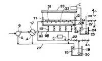
図3に、本発明の処理方法に用いる別の装置の概略構成図を示す。
図3で、畜糞、生ごみの堆肥化施設から発生した排ガスは、脱臭ファン6により間接冷却機17に導かれる。ここで、排ガスの温度を約30℃へ調整するが、この過程で生物脱臭装置11に入る前の結露水aなどのほとんどが捕集される。この結露水aなどは、脱臭ファン6や通気ダクトから発生した結露水aなどと一緒に、発酵結露水18として発酵結露水槽19に貯水する。
また、生物脱臭装置11において発生した排出水bなどは、生物脱臭装置11の床面部に集められた後、脱臭排出水23となり脱臭排出水槽24に貯水する。
これらの結露水などは、それぞれ異なった処理をする。
まず、発酵結露水槽19に貯水された発酵結露水18は、発酵結露水ポンプ20により、優先順位として、最初に堆肥化施設の発酵槽4での発酵原料への加水として使用する。その加水に使われなかった発酵結露水18は、生物脱臭装置11へ送り散水用に使用する。
【0028】
この場合、生物脱臭装置11での散水箇所は、脱臭層の下から100cmの部分とした。
また、脱臭排出水23は、脱臭排出水ポンプ25により優先順位として、まず生物脱臭装置11へ散水し、生物脱臭装置11に生息している脱臭用微生物の生息環境を保持すると共に、一部排出水に溶解しているアンモニア性窒素を亜硝酸、硝酸性窒素へ変換する。
この場合、生物脱臭装置11での散水箇所は、脱臭層の下から180cmの部分とした。
また、生物脱臭装置11へ有機物を供給するため、それぞれの発酵結露水18の場合は散水するライン22の途中、脱臭排出水23の場合は、散水ライン27の途中に、畜糞と生ごみから発生した浸出水cを、いずれも散水量の約0.5〜2%の割合で添加した。余剰の脱臭排出水23は、この後に液肥化、脱窒排水処理設備へ送り処理した。この実施例2の仕様などを表3に示す。
【0029】
【表3】
また、この生物脱臭システムは、5か月間の連続運転を行っているが、出口のアンモニア濃度は初期の値を維持している。
この結果から、従来の生物脱臭システムでのアンモニア濃度2.3〜3.4ppmと比較すると、0.1〜0.4ppmと低下し、かつ本方法により、長期間にわたり効果的にアンモニアの除去ができていることがわかった。
よって、本生物脱臭装置の通常運転時においても、脱臭用微生物の栄養源として有機物が必要で、その有機物として原料から発生する汚水が有効である。
【0031】
【発明の効果】
本発明によれば、次のような効果を奏することができる。
本発明では、発生した結露水は、生物脱臭装置の中途に散水することでアンモニアの拡散を防止できる。
このようにして、生物脱臭装置の中途に供給することで、生物脱臭装置に生息する微生物によりアンモニア性窒素を亜硝酸窒素、硝酸性窒素へ変換でき、後の脱窒装置での前処理としての硝酸性窒素への変換工程を簡略化できる。
また、生物脱臭装置の排出水は、すべてのアンモニア性窒素が硝化されると硝酸性窒素なるが、排ガスの供給が床部からのため、一部の排出水は十分に硝化される時間がないため、そのままアンモニア性窒素として排出水へ溶解している。これについても、最大限生物脱臭装置で硝化させるため、排出水を集水し、これを生物脱臭装置へ散布し、循環使用することで、排出水に含まれるアンモニア性窒素の大部分を硝酸性窒素へ変換できる。
上記の排出水と生物脱臭装置の散水過程を分離したことで、臭気の発生がない、排水処理の負荷が低減した脱臭装置とすることができる。
【0032】
また、生物脱臭装置の建設当初に、脱臭用微生物の繁殖を促す馴致に当たり、当初の立ちあがりを促進するため、少量の汚泥や窒素、リン分を供給することはよく行われている。
これは生物脱臭装置の立ちあがり時に、特に無機物の充填材を使用する場合には、当初の立ちあがり時にはほとんど脱臭用の微生物が付着していないため、脱臭用微生物を急速に増殖させるため、下水処理場やし尿処理場の活性汚泥を含んだ処理水などを添加することを行う。
しかし、従来の黒ぼく土などの土壌を採用している分には、排ガス中に含まれている有機物により、脱臭用微生物の生息に必要な有機物が供給されるためと、従来から黒ぼく土には多量の有機物や腐植が含まれているため、特に新規に有機物の供給を行わなくとも長期間脱臭性能は維持できた。
しかし、ゼオライト、廃鋳物砂など、無機物の脱臭材には、当初それらの脱臭用微生物はほとんど生息していないため、立ち上げ時当初にそれらの馴致を行うことは必須となっている。
【0033】
また、無機質の脱臭材では、ほとんど有機物が存在しないため、初期立ち上げ時の脱臭用微生物と同時に有機物が供給されるが、その有機物は数か月でなくなる。その後、脱臭性能を維持するためには、定期的に有機資材の供給を行わなければならない。
本発明では、この有機物について、原料である生ごみ、畜糞、汚泥などから浸出する有機物を多量に含んだ悪質な汚水を使用することで、脱臭材へ栄養源である有機物を与えることができる。
また、この汚水の供給量は、生物脱臭装置の全体散水量のわずか0.5〜2%程度でよく、かつ汚水は、すぐに生物脱臭用微生物の栄養源として分解してしまうため、汚水の追加による臭気の発生や排水水質の悪化などは発生しない。
【図面の簡単な説明】
【図1】本発明の処理方法に用いる装置の一例を示す概略構成図。
【図2】実施例1で脱臭効果の比較のために用いた生物脱臭装置の概略構成図。
【図3】本発明の処理方法に用いる装置の別の例を示す概略構成図。
【図4】堆肥化施設の脱臭フローを示す概略構成図。
【図5】従来の土壌脱臭装置の一例を示す概略構成図。
【図6】従来の土壌脱臭装置の他の例を示す概略構成図。
【図7】従来の生物脱臭システムのフローを示す概略構成図。
【図8】従来の生物脱臭システムの他のフローを示す概略構成図。
【符号の説明】
1:原料置場、2:原料置場建屋又はビニールシート、3:前処理室脱臭ファン、4:発酵槽、5:発酵槽建屋又はビニールシート、6:脱臭ファン、7:パドル式撹拌装置、8:発酵槽通気ファン、9:脱臭ダクト、10:脱臭装置、11:生物脱臭装置、12:脱臭材、13:壁、14:底面部、15:ダンパ、16:粘土質、17:冷却装置、18:発酵結露水、19:発酵結露水槽、20:発酵結露水ポンプ、21:結露水aなどのライン、22:結露水aなどの散水ライン、23:脱臭排出水、24:脱臭排出水槽、25:脱臭排出水ポンプ、26:排出水bなどのライン、27:排出水bなどの散水ライン、30、30A、30B:散水装置、31:発酵結露水散水装置、32:脱臭排出水散水装置、33:屋根、a:発酵結露水、b:脱臭排出水、c:汚水、d:排水、e:上水[0001]
BACKGROUND OF THE INVENTION
The present invention relates to the treatment of odorous gas generated from composting facilities, and in particular, in the fermentation treatment of various organic wastes such as food waste, sludge, livestock excrement and food waste, odors generated from composting facilities etc. The present invention relates to an odor gas processing method and apparatus for processing exhaust gas contained in a biological deodorization apparatus.
[0002]
[Prior art]
In conventional composting facilities, livestock excrement such as cattle, pigs and chicken excrement, sewage sludge, village drainage sludge, commi sludge, various sludges such as food factory sludge, mixed collection garbage, separated collection garbage, pruned branches, Organic waste such as dead fish, fish iliac and other marine waste, post-harvest plant residue, rice husk, rice straw, bark, wood chips, sawdust, and other organic waste are treated by aerobic or anaerobic fermentation. It was.
Since these raw materials are mostly septic raw materials, they have been carried into a composting facility and then put into a fermenter for aerobic fermentation to produce compost.
In the raw material stage, sulfur-based hydrogen sulfide, methyl mercaptan, etc. are already generated due to the decay of a part of the raw material at the time of delivery. Further, nitrogen-based ammonia, which is the main odor, is generated in a large amount when organic substances are decomposed in the process of aerobic fermentation in the fermenter.
In composting facilities, measures are taken to prevent odor pollution to the surrounding residents due to these odors.
[0003]
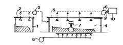
FIG. 4 shows a deodorization flow of the composting facility.
The composting raw material is primarily stored in the raw material storage place 1 and then put into the
In composting facilities, odors are generated during raw materials and fermentation.
Therefore, the raw material receiving part and the raw material storage 1 are stored in the raw material receiving building 2. The raw material storage 1 is covered with a vinyl sheet, and the air in the raw material storage is sucked by the pretreatment deodorizing fan 3 from the upper part of the raw material receiving building 2. In particular, in the
[0004]
When taking the above odor countermeasures, the air sucked from the
Various deodorization methods include water cleaning, chemical cleaning, activated carbon, ozone, combustion, and biological deodorization.
As a method of deodorizing equipment for exhaust gas from composting facilities, biological deodorization methods have been adopted in most of the above methods because of the properties of exhaust gas generated during the fermentation process and sucked from the composting facilities. It was.
That is, as the odor component of the exhaust gas to be sucked in, there is some variation in the type of organic waste that is the raw material to be composted and the fermentation treatment method, but the odor component generated from the raw material is caused by decay Sulfur-based hydrogen sulfide, methyl mercaptan and the like are included in an amount of about 0.01 to 0.1 ppm, and nitrogen-based ammonia generated in the aerobic fermentation process that occupies most of the odor component is included in an amount of 100 to 500 ppm. .
Further, as the properties of the exhaust gas, the temperature is increased by fermentation of organic waste, and the temperature is 20 to 40 ° C. and the relative humidity is 80 to 100% due to evaporation of water vapor.
[0005]
Conventionally, as a deodorizing method for treating these exhaust gases, a biological deodorizing apparatus has been used for reasons such as high ammonia concentration, high relative humidity, and little operating cost. Moreover, the soil is mostly used as a filler for the biological deodorization device, and therefore, the biological deodorization device of the composting facility is usually adopted as much as the soil deodorization device is shown.
In FIG. 5, sectional drawing of a soil deodorizing apparatus is shown.
The
In addition to the above, many types and numbers of deodorizing microorganisms inhabit the soil, but their functions cannot be exhibited unless the habitat environment of the deodorizing microorganisms is always maintained appropriately. That is, uniform aerobic atmosphere, supply of organic matter, retention of moisture.
[0006]
However, in the
In particular, after the rain, the rain that has fallen on the
As a result, the odor that was worse than usual during the rain came to the surroundings.
[0007]
FIG. 6 shows a cross section of the improved soil deodorization apparatus.
In order to improve the above, the
In addition, in order to prevent the exhaust gas from being blown through, a
In addition, a method of providing a
[0008]
In addition, about 50 cm from the end of the floor surface portion of the
However, even when such measures are employed, it is difficult to drastically improve the particle size, air permeability, and water retention capacity as long as soil is employed. Therefore, in the soil deodorizing
Therefore, recently, various new deodorizing materials have begun to be used as the material for the filling material of the biological deodorizing device from the three points of reduction of pressure loss, prevention of increase of pressure loss due to aging, and improvement of deodorizing performance.
As these deodorizing materials, bark and compost are used for organic materials, and zeolite, ceramics, rock wool and the like are used for inorganic deodorizing materials.
[0009]
Among these deodorizing materials, organic deodorizing materials have the advantages of low apparent specific gravity, low pressure loss, easy availability, etc., but when used as deodorizing materials, the organic deodorizing materials gradually become older with age. However, it is difficult to take the labor for the replacement of the organic deodorizing material in about 1 to 3 years.
However, since the replaced organic deodorizing material can be used again as a raw material for compost, the use of bark as a moisture conditioner and raw material in composting facilities is a primary application for produced compost. Since it can be recycled, it is hard to throw away as an effective use of resources.
Zeolite, ceramics, and rock wool, which are inorganic deodorizing materials, are all porous substances in which deodorizing microorganisms tend to live.
In particular, zeolite is a deodorizing material which has recently attracted attention due to its physical adsorption action and its porous nature.
[0010]
In addition, these inorganic deodorizing materials are materials that can be used permanently because they hardly decompose or alter themselves as compared with organic deodorizing materials.
These can be divided into zeolites produced from natural mountains, artificially produced ceramics, and rock wool.
However, since these deodorizing materials themselves are used in large quantities for other purposes as products, the cost is considerably higher than conventional soil and organic deodorizing materials.
However, since these have good air permeability as compared with soil, the deposition height can be about 200 to 250 cm compared with 50 to 100 cm employed in the case of soil.
Thereby, in the biological deodorization apparatus using zeolite and rock wool, compared with the installation area in the soil deodorization apparatus, the area ratio may be 1 / 2.5 to 1/5. It can be reduced by 30%.
[0011]
Therefore, in recent years, biological deodorization apparatuses using zeolite and rock wool are increasing because they can be installed in a small site area in a composting facility and construction costs can be reduced.
In particular, among these inorganic deodorizing materials, zeolite is handled and its adoption is rapidly increasing due to its deodorizing performance.
However, the production area of zeolite is limited, and in the composting facility of approximately 10 t / d, the biological deodorization area is 100 m.2 The volume of zeolite used is 200mThree Therefore, it is difficult to obtain a predetermined zeolite in a short period of time, and depending on the construction site, the transportation cost of the zeolite is high, and a high-performance and inexpensive deodorizing material that can replace the zeolite has been demanded.
[0012]
Next, the background and problems of the biological deodorization system are shown.
FIG. 7 shows a flow of a conventional biological deodorization system.
In this biological deodorization system, black debris or a mixture of black debris and volcanic reki was used as the
The
The exhaust gas sucked from the fermenter was sent to the
[0013]
In addition, a watering
However, in this biological deodorization system, the air temperature in the fermenter room was 40-50 ° C in the composting facility accompanying aerobic fermentation in summer, and this high-temperature exhaust gas was directly sent to the biological deodorization device. The habitat environment of deodorizing microorganisms inhabiting the deodorizing apparatus deteriorated rapidly, and the deodorizing performance often deteriorated due to dormancy and death of the deodorizing microorganisms.
In addition, since several years ago, it was necessary to improve the environment of the entire region, and in order to prevent contamination of soil and groundwater by nitrogenous organic matter, there was a need to take measures against underground penetration of wastewater generated from biological deodorization equipment. .
As described above, since the maintenance of stable operation throughout the year in the biological deodorization apparatus and measures against discharged water have been required, new biological deodorization apparatuses that have improved these have been introduced.
[0014]
FIG. 8 shows a flow of a recent biological deodorization system.
A pretreatment method for cooling the exhaust gas was introduced to solve the decline in summer deodorization performance of the biological deodorization device.
The deodorizing microorganism that contributes to deodorization can maintain its habitat environment at approximately 40 ° C. or lower, and can exhibit the deodorizing performance. Therefore, it is passed through the cooler 17 to reduce the exhaust gas containing odor to 40 ° C. or lower. I came.
There are two cooling methods, indirect and direct cooling.
In the indirect cooling method, exhaust gas is passed through the inner pipe of the indirect cooler and the outside is cooled with cooling water or air. In the case of the indirect cooling method, since the outside air temperature exceeds 30 ° C. as a cooling medium, a method of cooling with cooling water is often adopted without using air.
In this case, when abundant water can be obtained nearby as the cooling water for the cooling medium, the cooling water whose temperature has been increased by one pass is drained into the rainwater ditch as it is. When cooling water is difficult to obtain, a cooling tower is used to circulate and use the cooling water.
[0015]
In the case of the indirect cooling method, condensed water mainly composed of ammonia is generated from the cooled exhaust gas. This condensed water is generated only by the difference between the inlet temperature and the outlet temperature of the exhaust gas.
Next, the direct cooling method is a method in which exhaust gas is guided to the
In this case, dew condensation water is generated in the scrubber as described above, and this dew condensation water is combined with the scrubber cooling water.
In the case of the direct cooling method, the waste water mixed with the dew condensation water and the cooling water is circulated and used by the pump in the
Further, in the
[0016]
In order to prevent this discharged water from penetrating underground, concrete is placed on the
In this biological deodorizing system, the deodorized
[0017]
However, in this biological deodorization system, since a large amount of ammonia is dissolved in the condensed water a generated in the
Therefore, it is important to operate biological deodorization equipment without generating odors, and at the same time improve the quality of condensed water, and reduce subsequent denitrification, construction costs for wastewater treatment facilities, and operating costs. It was.
[0018]
[Problems to be solved by the invention]
The present invention has been made in view of the above-described problems of the prior art, and in a biological deodorization apparatus installed in a composting facility for various organic wastes, dew condensation generated in the process of deodorizing exhaust gas containing odors. It is an object of the present invention to provide an odor gas treatment method and apparatus for economically treating discharged water such as water.
[0019]
[Means for Solving the Problems]
In order to solve the above problems, in the present invention, exhaust gas containing odor generated from a composting facility,Has a packed bed filled with deodorizing material In the method of treating with the biological deodorization apparatus, the dew condensation water generated from the composting facility to the front of the biological deodorization apparatus and the discharged water in the biological deodorization apparatus areIn the packed bed filled with the deodorizing material, SeparatelySupply The odor gas treatment method is characterized by processing.
In the odor gas treatment method,Previous The discharge waterStudent Deodorization deviceTo supply ProcessThe rest Either liquid fertilization or waste water denitrification treatment can be used alone or in combination., Charge It is good to supply and process in the middle of the filling layer, and the dew condensation water and the discharged water areTo supply When processing, the sewage generated from various raw materials carried into the composting facility can be added and processed.
Further, in the present invention, exhaust gas containing odor generated from a composting facility,Has a packed bed filled with deodorizing material In the apparatus to be processed by the biological deodorization apparatus, the condensed water generated before the biological deodorization apparatus is collected from the composting facility, and theBiological deodorization apparatusIn packed bed filled with deodorizing material And the drainage water from the biological deodorization device, The biological deodorization apparatusIn packed bed filled with deodorizing material The path leading to, The odor gas treatment apparatus is characterized by being provided separately.
[0020]
DETAILED DESCRIPTION OF THE INVENTION
The biological deodorization method of the present invention is generated in the biological deodorization apparatus, such as dew condensation water generated up to the previous stage of the biological deodorization apparatus when the exhaust gas containing odor generated from the composting facility is deodorized by the biological deodorization apparatus. Dispose of waste water separately.
Condensation water generated up to the previous stage of the biological deodorization apparatus is treated by any one or a combination method for adjusting moisture in a composting facility or biological deodorization apparatus, and discharged in the biological deodorization apparatus. Water or the like can be treated for adjusting the water content in a composting facility or biological deodorizing apparatus, or can be treated by any one of or a combination of liquid fertilization and denitrification drainage treatment.
In addition, when the dew condensation water generated up to the previous stage of the biological deodorization apparatus and the discharged water generated in the biological deodorization apparatus are treated for moisture adjustment of the biological deodorization apparatus, the biological deodorization apparatus is filled. It is better to supply condensed water from the middle of the packed bed, and in addition, when deodorizing exhaust gas containing odor generated from composting facilities with a biological deodorization device, in the previous stage of the biological deodorization device or in the biological deodorization device Sewage generated from various raw materials carried into the composting facility can be added to the generated condensed water and discharged water.
As the deodorizing material for the filler to be filled in the biological deodorizing apparatus used in the composting facility, it is preferable to mainly use waste foundry sand.
[0021]
【Example】
Hereinafter, the present invention will be described more specifically with reference to examples.
Example 1
First, the test which investigates the difference in the deodorizing effect by the kind of deodorizing material was done. A schematic configuration diagram of the biological deodorization apparatus used in this test is shown in FIG.
As an odor generation source, the odor from the garbage disposal discharged from the factory cafeteria was used.
The biological deodorization apparatus in FIG. 2 is a sealed
The watering
In this test, the
Table 1 shows the general operating conditions and results of the biological deodorization apparatus in this test.
[0022]
[Table 1]
From these results, it was found that the deodorizing material using waste foundry sand had less pressure loss and superior deodorizing performance than that using zeolite.
Regarding the deodorization performance of waste foundry sand, it has been experimentally confirmed that it is effective against sulfur-type odors such as hydrogen sulfide and methyl mercaptan. The same applies to nitrogen-type odors such as ammonia. However, the results of this test confirmed that it was effective against nitrogenous odors.
In addition, as an additional test, in the conditions of Test Example 3 above, the other condensed water a and the discharged water b were gathered together under the same conditions, and sprinkled instead of clean water. However, the ammonia concentration at the outlet was 2.3 to 3.4 ppm.
From this result, it was found that ammonia dissolved in condensed water a and the like was dissociated at the time of sprinkling and was a source of odor.
[0024]
Based on these situations, the test apparatus was modified to be an apparatus used in the processing method of the present invention.
A schematic diagram of the apparatus is shown in FIG.
The difference from FIG. 2 is that dew condensation water a before the biological deodorization device generated in the deodorization process is stored in the fermentation dew
Table 2 shows the specifications and test results of the biological deodorization apparatus of Example 1 of the present invention.
[0025]
[Table 2]
According to Table 2, when condensed water is supplied into the deodorizing material, it is possible to prevent dissociation during the sprinkling of ammonia dissolved in the discharged water.
In this case, the condensed water a in which a large amount of ammonia is dissolved indicates that, when supplied from the central portion of the deodorizing layer, the dissociated ammonia generated during watering can be deodorized by the deodorizing layer.
When the operation was continued for about two months under the conditions of Test Example 5, the ammonia concentration at the outlet gradually increased and increased to 1.2 to 1.5 ppm.
The cause of this was assumed to be that the habitat of the microorganisms was deteriorated because there was no supply of organic matter as nutrients to the deodorizing microorganisms. In normal wastewater treatment, phosphoric acid and methanol are added as organic substances in this case. This time, when sewage leached from raw garbage used as a raw material was added about 0.5% of the sprinkling amount, the ammonia concentration dropped to the initial level of 0.1-0.3 ppm in about one week. did.
Therefore, it was found that organic waste such as garbage can be replaced by sewage as a nutrient source for deodorizing microorganisms.
[0027]
Example 2
In FIG. 3, the schematic block diagram of another apparatus used for the processing method of this invention is shown.
In FIG. 3, the exhaust gas generated from the composting facility for livestock manure and garbage is guided to the
Further, the discharged water b generated in the
Each of these condensed water is treated differently.
First, the fermented
[0028]
In this case, the water sprinkling part in the
In addition, the deodorized
In this case, the water sprinkling part in the
In addition, in order to supply organic matter to the
[0029]
[Table 3]
In addition, this biological deodorization system has been operated continuously for 5 months, but the ammonia concentration at the outlet is maintained at the initial value.
From this result, compared with the ammonia concentration 2.3 to 3.4 ppm in the conventional biological deodorization system, the ammonia concentration is reduced to 0.1 to 0.4 ppm, and this method effectively removes ammonia over a long period of time. I understood that it was made.
Therefore, even during normal operation of the present biological deodorization apparatus, organic matter is required as a nutrient source for the microorganisms for deodorization, and sewage generated from the raw material is effective as the organic matter.
[0031]
【The invention's effect】
According to the present invention, the following effects can be achieved.
In the present invention, the generated condensed water can be sprayed in the middle of the biological deodorization device to prevent the diffusion of ammonia.
In this way, by supplying in the middle of the biological deodorization device, ammonia nitrogen can be converted into nitrite and nitrate nitrogen by microorganisms that inhabit the biological deodorization device, and as a pretreatment in the later denitrification device The conversion process to nitrate nitrogen can be simplified.
Moreover, when all ammonia nitrogen is nitrified, the effluent from the biological deodorization device becomes nitrate nitrogen, but since the exhaust gas is supplied from the floor, some effluent does not have enough time to be nitrified. Therefore, it is dissolved in the discharged water as ammonia nitrogen as it is. Again, in order to nitrify with the biological deodorization equipment as much as possible, the drainage water is collected, sprayed to the biological deodorization equipment, and recycled, so that most of the ammonia nitrogen contained in the wastewater is nitrate-based. Can convert to nitrogen.
By separating the water discharge process of the discharged water and the biological deodorization apparatus, it is possible to provide a deodorization apparatus that does not generate odor and has a reduced wastewater treatment load.
[0032]
In addition, at the beginning of construction of a biological deodorization device, a small amount of sludge, nitrogen, and phosphorus are often supplied in order to promote the start-up in order to promote the growth of microorganisms for deodorization.
This is because when a biological deodorizing device is started up, especially when inorganic fillers are used, since there are almost no deodorizing microorganisms attached at the time of initial startup, the deodorizing microorganisms are rapidly grown. Add treated water containing activated sludge from the palm urine treatment plant.
However, the amount of organic matter contained in the exhaust gas is used to supply the organic matter necessary for the deodorizing microorganisms to be used in the conventional soil such as black soil. Since a large amount of organic matter and humus are contained in the plant, the deodorizing performance can be maintained for a long time without supplying new organic matter.
However, inorganic deodorizing materials such as zeolite and waste foundry sand are rarely inhabited by microorganisms for deodorizing them at the beginning, so it is essential to acclimate them at the beginning of startup.
[0033]
In addition, since the inorganic deodorizing material has almost no organic matter, the organic matter is supplied at the same time as the deodorizing microorganisms at the initial start-up, but the organic matter is no longer several months old. Thereafter, in order to maintain the deodorizing performance, the organic material must be supplied periodically.
In this invention, the organic substance which is a nutrient source can be given to a deodorizing material by using the vicious sewage containing a large amount of the organic substance leached from raw materials such as garbage, livestock dung, and sludge.
In addition, the supply amount of this sewage may be only about 0.5 to 2% of the total amount of water sprayed by the biological deodorization device, and the sewage is immediately decomposed as a nutrient source for microorganisms for biological deodorization. No additional odor or wastewater quality deterioration will occur.
[Brief description of the drawings]
FIG. 1 is a schematic configuration diagram showing an example of an apparatus used in a processing method of the present invention.
FIG. 2 is a schematic configuration diagram of a biological deodorization apparatus used in Example 1 for comparison of a deodorizing effect.
FIG. 3 is a schematic configuration diagram showing another example of an apparatus used in the processing method of the present invention.
FIG. 4 is a schematic configuration diagram showing a deodorization flow of a composting facility.
FIG. 5 is a schematic configuration diagram showing an example of a conventional soil deodorization apparatus.
FIG. 6 is a schematic configuration diagram showing another example of a conventional soil deodorizing apparatus.
FIG. 7 is a schematic configuration diagram showing a flow of a conventional biological deodorization system.
FIG. 8 is a schematic configuration diagram showing another flow of the conventional biological deodorization system.
[Explanation of symbols]
1: raw material storage building, 2: raw material storage building or vinyl sheet, 3: pre-treatment room deodorizing fan, 4: fermenter, 5: fermenter building or vinyl sheet, 6: deodorizing fan, 7: paddle type stirring device, 8: Fermenter aeration fan, 9: deodorizing duct, 10: deodorizing device, 11: biological deodorizing device, 12: deodorizing material, 13: wall, 14: bottom part, 15: damper, 16: clay, 17: cooling device, 18 : Fermentation dew condensation water, 19: Fermentation dew condensation water tank, 20: Fermentation dew condensation water pump, 21: Lines such as dew condensation water a, 22: Sprinkling line such as dew condensation water a, 23: Deodorization discharge water, 24: Deodorization discharge water tank, 25 : Deodorized drainage pump, 26: Line of discharged water b, 27: Sprinkling line of discharged water b, 30, 30A, 30B: Sprinkler, 31: Fermentation dew condensation water sprinkler, 32: Deodorized drainage sprinkler, 33: roof, a: fermentation condensation , B: deodorizing effluent, c: sewage, d: Drainage, e: tap water
Claims (5)
Translated fromJapanesePriority Applications (1)
| Application Number | Priority Date | Filing Date | Title |
|---|---|---|---|
| JP2000349444AJP3638010B2 (en) | 2000-11-16 | 2000-11-16 | Method and apparatus for treating odorous gas generated from composting facilities |
Applications Claiming Priority (1)
| Application Number | Priority Date | Filing Date | Title |
|---|---|---|---|
| JP2000349444AJP3638010B2 (en) | 2000-11-16 | 2000-11-16 | Method and apparatus for treating odorous gas generated from composting facilities |
Publications (2)
| Publication Number | Publication Date |
|---|---|
| JP2002153721A JP2002153721A (en) | 2002-05-28 |
| JP3638010B2true JP3638010B2 (en) | 2005-04-13 |
Family
ID=18822846
Family Applications (1)
| Application Number | Title | Priority Date | Filing Date |
|---|---|---|---|
| JP2000349444AExpired - Fee RelatedJP3638010B2 (en) | 2000-11-16 | 2000-11-16 | Method and apparatus for treating odorous gas generated from composting facilities |
Country Status (1)
| Country | Link |
|---|---|
| JP (1) | JP3638010B2 (en) |
Families Citing this family (6)
| Publication number | Priority date | Publication date | Assignee | Title |
|---|---|---|---|---|
| JP3831800B2 (en)* | 2004-08-23 | 2006-10-11 | 伸也 渡部 | Method and apparatus for collecting and utilizing malodorous components in compost |
| JP2009007229A (en)* | 2007-06-29 | 2009-01-15 | Shinshu Green Co Ltd | Fertilizer and its manufacturing process |
| JP2018168046A (en)* | 2017-03-30 | 2018-11-01 | 宇部興産株式会社 | Cement clinker manufacturing method and cement manufacturing method |
| CN107511393A (en)* | 2017-09-25 | 2017-12-26 | 湖南惠格生态农业发展有限公司 | A kind of biological organic fertilizer automatic production line |
| EP4029825A4 (en) | 2019-09-13 | 2023-10-11 | JFR Co., Ltd. | Nitrogen recovery method, nitrogen recovery device, and product obtained by same |
| JP7640152B1 (en)* | 2024-06-04 | 2025-03-05 | 特定非営利活動法人アーステクノ | Sludge treatment facility |
- 2000
- 2000-11-16JPJP2000349444Apatent/JP3638010B2/ennot_activeExpired - Fee Related
Also Published As
| Publication number | Publication date |
|---|---|
| JP2002153721A (en) | 2002-05-28 |
Similar Documents
| Publication | Publication Date | Title |
|---|---|---|
| AP491A (en) | Method and apparatus for disposal and treatment of waste. | |
| US7585413B2 (en) | Method and apparatus for treating animal waste and wastewater | |
| EP0863856B1 (en) | Composting system and method | |
| US6136185A (en) | Aerobic biodegradable waste treatment system for large scale animal husbandry operations | |
| US20050201831A1 (en) | Landfill structure using concept of multi-layered reactors and method for operating the same | |
| Petersen et al. | Perspective greenhouse gas mitigation by covers on livestock slurry tanks and lagoons? | |
| JP3638010B2 (en) | Method and apparatus for treating odorous gas generated from composting facilities | |
| Rynk et al. | Commercial compost production systems | |
| JP4527610B2 (en) | Method and apparatus for fertilizers such as garbage | |
| WO2020184159A1 (en) | Microorganism deodorizing device and deodorization treatment system | |
| Nakasaki et al. | Effect of bulking agent on the reduction of NH3emissions during thermophilic composting of night-soil sludge | |
| US6254776B1 (en) | System and method for treating animal waste | |
| US6630072B2 (en) | Methods and apparatuses for treating waste water | |
| KR102137399B1 (en) | ATAD type Swine Wastewater Treatment System for minimizing odor | |
| JPH0769765A (en) | Regeneration treatment of excrement or animal feces and treating facility for excrement or animal feces | |
| US6602464B1 (en) | Method and apparatus for treating digestible and odiferous waste | |
| JPH11228270A (en) | Organic matter composting facility and method for producing organic matter into compost | |
| JP3845683B2 (en) | Deodorizing device | |
| Vanderholm et al. | Management of livestock wastes for water resource protection | |
| KR20010085010A (en) | Device and method compost manufacturing | |
| US6922941B2 (en) | Method for making a plant-cultivating web from excretive sludge of domestic animals | |
| Gałwa-Widera et al. | Biofiltration–an ecological method of removing odors generated during drying sewage sludge-case study | |
| JP3412024B2 (en) | Dioxin reducing agent and method for reducing dioxins using the same | |
| KR100653130B1 (en) | Microorganism deodorizer using aeration modifier | |
| CN101624304A (en) | Improvements in mechanical composting systems |
Legal Events
| Date | Code | Title | Description |
|---|---|---|---|
| A977 | Report on retrieval | Free format text:JAPANESE INTERMEDIATE CODE: A971007 Effective date:20041013 | |
| A131 | Notification of reasons for refusal | Free format text:JAPANESE INTERMEDIATE CODE: A131 Effective date:20041015 | |
| A521 | Written amendment | Free format text:JAPANESE INTERMEDIATE CODE: A523 Effective date:20041206 | |
| TRDD | Decision of grant or rejection written | ||
| A01 | Written decision to grant a patent or to grant a registration (utility model) | Free format text:JAPANESE INTERMEDIATE CODE: A01 Effective date:20050105 | |
| A61 | First payment of annual fees (during grant procedure) | Free format text:JAPANESE INTERMEDIATE CODE: A61 Effective date:20050105 | |
| R150 | Certificate of patent or registration of utility model | Free format text:JAPANESE INTERMEDIATE CODE: R150 | |
| FPAY | Renewal fee payment (event date is renewal date of database) | Free format text:PAYMENT UNTIL: 20100121 Year of fee payment:5 | |
| FPAY | Renewal fee payment (event date is renewal date of database) | Free format text:PAYMENT UNTIL: 20110121 Year of fee payment:6 | |
| S111 | Request for change of ownership or part of ownership | Free format text:JAPANESE INTERMEDIATE CODE: R313111 | |
| FPAY | Renewal fee payment (event date is renewal date of database) | Free format text:PAYMENT UNTIL: 20110121 Year of fee payment:6 | |
| R350 | Written notification of registration of transfer | Free format text:JAPANESE INTERMEDIATE CODE: R350 | |
| FPAY | Renewal fee payment (event date is renewal date of database) | Free format text:PAYMENT UNTIL: 20110121 Year of fee payment:6 | |
| FPAY | Renewal fee payment (event date is renewal date of database) | Free format text:PAYMENT UNTIL: 20120121 Year of fee payment:7 | |
| LAPS | Cancellation because of no payment of annual fees |