JP3637163B2 - Energy storage power supply - Google Patents
Energy storage power supplyDownload PDFInfo
- Publication number
- JP3637163B2 JP3637163B2JP27862096AJP27862096AJP3637163B2JP 3637163 B2JP3637163 B2JP 3637163B2JP 27862096 AJP27862096 AJP 27862096AJP 27862096 AJP27862096 AJP 27862096AJP 3637163 B2JP3637163 B2JP 3637163B2
- Authority
- JP
- Japan
- Prior art keywords
- capacitor
- substrate
- power supply
- electronic circuit
- capacitor cell
- Prior art date
- Legal status (The legal status is an assumption and is not a legal conclusion. Google has not performed a legal analysis and makes no representation as to the accuracy of the status listed.)
- Expired - Fee Related
Links
Images


Classifications
- H—ELECTRICITY
- H02—GENERATION; CONVERSION OR DISTRIBUTION OF ELECTRIC POWER
- H02M—APPARATUS FOR CONVERSION BETWEEN AC AND AC, BETWEEN AC AND DC, OR BETWEEN DC AND DC, AND FOR USE WITH MAINS OR SIMILAR POWER SUPPLY SYSTEMS; CONVERSION OF DC OR AC INPUT POWER INTO SURGE OUTPUT POWER; CONTROL OR REGULATION THEREOF
- H02M7/00—Conversion of AC power input into DC power output; Conversion of DC power input into AC power output
- H02M7/003—Constructional details, e.g. physical layout, assembly, wiring or busbar connections
Landscapes
- Engineering & Computer Science (AREA)
- Power Engineering (AREA)
- Electric Double-Layer Capacitors Or The Like (AREA)
- Electric Propulsion And Braking For Vehicles (AREA)
- Direct Current Feeding And Distribution (AREA)
- Charge And Discharge Circuits For Batteries Or The Like (AREA)
- Inverter Devices (AREA)
Abstract
Description
Translated fromJapanese【0001】
【発明の属する技術分野】
本発明は、蓄電式電源装置に関し、特に電気自動車用の蓄電式電源装置に関する。
【0002】
【従来の技術】
従来、この種の電気自動車用の蓄電式電源装置は、複数のコンデンサセルがバスバーを介して直列に接続されたコンデンサブロックの少なくとも2つと、前記コンデンサセルのそれぞれに接続されており、当該コンデンサセルの作動を制御する電子回路の複数とを備える。
【0003】
また、上記蓄電式電源装置のコンデンサブロックにおいて、直列に接続されたコンデンサセルは電気二重層型であると共にその数は約100個であり、1つのコンデンサセルの電圧は3.5Vである。従って、1つのコンデンサブロックの満充電時の電圧は約350Vである。この蓄電式電源装置は、電源装置の残容量やエンジン運転状態及び車輌の走行状態に応じて2つのコンデンサブロックの接続を並列又は直列に切り換えて使用される。
【0004】
従来、このような蓄電式電源装置において、前記電子回路のそれぞれは、コンデンサセルに一体的に設けられておらず、コンデンサセルとは別のところ、すなわち、一例としてモータードライバ(PDU)としてのパルス変調(PWM)ドライバの一部やモーターの近傍に取付けられていた。
【0005】
【発明が解決しようとする課題】
上述のように、従来の電気自動車用の蓄電式電源装置では、前記電子回路のそれぞれは、コンデンサセルに一体に設けられておらず、コンデンサセルとは別のところに設けられているので、コンデンサセルの端子と電子回路との間の配線長さが長くなり配線のインピーダンスが大きくなる。その結果、蓄電式電源装置のコンデンサセル内の電圧降下が大きいという問題があった。
【0006】
本発明の目的は、コンデンサセルの端子と電子回路との間の配線のインピーダンスを小さくしてコンデンサセル内の電圧降下を低減することができ、またバスバー及び電子回路のコンデンサセルへの取付構造を簡易化できる蓄電装置を提供することにある。
【0007】
【課題を解決するための手段】
上記目的を達成するために、請求項1の蓄電式電源装置は、複数のコンデンサセルがバスバーを介して直列に接続されたコンデンサブロックと、前記コンデンサセルのそれぞれに接続されており、当該コンデンサセルの作動を制御する電子回路の複数を備える電源装置において、下部に凹部を有する基板が前記コンデンサセルのそれぞれにおける上面に取付けられ、前記バスバーと前記電子回路とが前記凹部の底面に取付けられていることを特徴とする。
【0008】
請求項1の蓄電式電源装置によれば、下部に凹部を有する基板がコンデンサセルのそれぞれにおける上面に取付けられ、バスバーと電子回路とが凹部の底面に取付けられているので、コンデンサセルの端子と電子回路との間の配線長さ及びバスバーの長さを最短にすることができ、配線のインピーダンスを低減させて蓄電式電源装置のコンデンサセル内の電圧降下を低減することができ、バスバー及び電子回路のコンデンサセルへの取付構造を簡易化できる。
【0011】
請求項2の蓄電式電源装置は、請求項1の蓄電式電源装置において、前記基板に放熱用フィンが設けられていることを特徴とする。
【0012】
請求項2の蓄電式電源装置によれば、基板に放熱用フィンが設けられているので、バスバー等の発熱によるコンデンサセルの温度上昇を防止することができる。
【0013】
請求項3の蓄電式電源装置は、請求項1又は2の蓄電式電源装置において、前記基板が絶縁基板であることを特徴とする。
【0014】
請求項4の蓄電式電源装置は、請求項1から3のいずれか1項の蓄電式電源装置において、電気自動車に使用されることを特徴とする。
【0015】
【発明の実施の形態】
以下、図を参照しながら、本発明の第1の実施の形態に係る蓄電式電源装置を説明する。
【0016】
図1は、本発明の第1の実施の形態に係る蓄電式電源装置の構成を示すブロック図である。
【0017】
電気自動車は、蓄電式電源装置1、パルス幅変調(PWM)ドライバ14、電動モータ16及びモータコントロールECU25を有する。PWMドライバ14はモータコントロールECU25からの制御信号にしたがって電動モータ16に電力を供給する。電動モータ16は図示しない車輪に動力を伝達する。
【0018】
蓄電式電源装置1は、一対のコンデンサブロック3,4、切換スイッチ7,8、DC−DCコンバータ11及びコンデンサマネジメントECU21を有し、PWMドライバ14に一定電圧を供給する。なお、図1にはコンデンサブロック3,4を充電する回路は省略されている。
【0019】
コンデンサブロック3,4は、それぞれ100個直列に接続された3.5V仕様の電気二重層型コンデンサセル27,28を有し、満充電時に350Vの電圧を出力する。
【0020】
コンデンサセル27,28は、コンデンサ27a,28a及びバイパススイッチ27b,28bを有する。また、コンデンサ27a,28aの近傍には、コンデンサ27a,28aの電圧を検出する電圧センサ27c,28cと、コンデンサ27a,28aの温度を検出する温度センサ27d,28dとが設けられている。
【0021】
電圧センサ27c,28cにより検出されたコンデンサ27a,28aの電圧が所定値より低くコンデンサ27a,28aが劣化したと判別されたとき、又は、温度センサ27d,28dにより検出されたコンデンサセル27a,28aの温度が60度より高くなったと判別されたとき、コンデンサマネジメントECU21によってバイパススイッチ27b,28bが切り替わり、両端子はコンデンサ27a,28aを介さずバイパスする。
【0022】
コンデンサマネジメントECU21は、周知のCPU、ROM、RAM、タイマ、I/Oインターフェース、通信インターフェースなどから構成される。
【0023】
また、モータントロールECU25は、周知のCPU、ROM、RAM、タイマ、I/Oインターフェース、通信インターフェースの他、電源装置の残容量、エンジン運転状態及び車輌の走行状態を検出する各種センサ26を備えており、通信インターフェースを介してコンデンサマネジメントECU21に運転状態に応じた指令を出力する。各種センサ26としては、モータ回転数検出センサ、車速センサ、アクセル開度センサなどが挙げられる。
【0024】
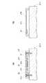
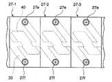
図2は、図1の蓄電式電源装置におけるコンデンサブロック3の部分平面図であり、図3(a)は、図2のA−A’断面図であり、図3(b)は図2のB−B’断面図である。
【0025】
図2において、複数のコンデンサセル27−1〜27−5が水平方向に配列されている。コンデンサセル27−1〜27−5の各構成は同じであり、以下、コンデンサセル27−1に注目して説明する。
【0026】
コンデンサセル27−1の上面には、正極端子27eと負極端子27fとが所定の間隔で設けられている。コンデンサセル27−2の負極端子27fは、コンデンサセル27−1の正極端子27eに対向しており、コンデンサセル27−2の正極端子27eはコンデンサセル27−1の負極端子27fに対向している。
【0027】
コンデンサセル27−1の上面において、コンデンサセル27−1の正極端子27eとコンデンサセル27−2の負極端子27fとは略コの字形かつ段付きのバスバー30で接続されており、コンデンサセル27−1の負極端子27fと隣接するコンデンサセルの正極端子とは略コの字形かつ段付きのバスバー31で接続されている。バスバー30,31の各厚さは1〜5mmである。正極端子27e及び負極端子27fはそれぞれ電極ボルトで構成されており、バスバー30,31及び後述する基板27hをコンデンサセル27−1に固定する役目も果たす(図3(a))。
【0028】
コンデンサセル27−1の上面において、外形がコンデンサセル27−1の平面形状に適合した基板27hが載置されている。基板27hには、正極端子27e及び負極基板27fの位置に対応して正極端子27e及び負極基板27fの各頭部を収容するような孔があけられており、その下面に後述する電子回路基板40及びバスバー30及び31を収容するような凹部27h’を下面に有する。
【0029】
また、図3(a)に示すように、凹部27h’の底部には、スイッチ27b,28b等の電子部品40aが取付けられた電子回路基板40が取付けられている。電子回路基板40の一端にはバスバー30の端部がスポット溶接等により接続されており、電子回路基板40の他端にはバスバー31の端部がスポット溶接等により接続されている。さらに、図3(b)に示すように、バスバー30,31の中間部は基板27hの下面に当接している。
【0030】
それぞれ電極ボルトで構成された正極端子27e及び負極端子27fは、バスバー30,31及び基板27hをコンデンサセル27−1に固定する。
【0031】
以上の構成により、電子回路基板40及びバスバー30及び31を凹部27h’に収容するので、電子回路基板40及びバスバー30及び31の機械的破損を防止できる。なお、この電子回路基板40及びバスバー30及び31を凹部27h’に収容せずに、基板27hの上部に取付けてもよい。これにより、電子回路基板40の脱着が容易になる。
【0032】
また、基板27hは、絶縁機能を有する基板であってもよい。これにより、短絡による故障や事故を防止することができる。基板27hの材料は、セラミックス、エポキシ樹脂、ガラス、金属等から成り、絶縁材料としては、セラミックス、エポキシ樹脂、ガラスが選択される。基板27hが絶縁材料で構成されれば、コンデンサセル27−1の放電を防止することができる。
【0033】
本実施の形態によれば、バスバー30,31と電子回路基板40とがコンデンサセル27−1上に実装されているので、コンデンサセル27−1の端子27e,27fと電子回路基板40との間の配線長さ及びバスバー30,31の長さを最短にすることができ、配線のインピーダンスを低減させて蓄電式電源装置1のコンデンサセル27−1内の電圧降下を実質的に低減することができる。
【0034】
前記実施の形態では、正極端子27eと負極端子27fとは、コンデンサセル27−2の負極端子27fがコンデンサセル27−1の正極端子27eに対向し、コンデンサセル27−2の正極端子27eがコンデンサセル27−1の負極端子27fに対向するように、交互に配列されているが、本発明の第1の実施の形態に係る蓄電式電源装置の変形例を示す図4のように、コンデンサセル27−2の正極端子27eがコンデンサセル27−1の正極端子27eに対向し、コンデンサセル27−2の負極端子27fがコンデンサセル27−1の負極端子27fに対向するように、正極端子27e及び負極端子27fがそれぞれ同一側に配列されてもよい。この場合は、バスバー33の形状は前記実施の形態におけるバスバー30,31と異なり、図4に示す如くとなる。
【0035】
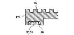
図5は、本発明の第1の実施の形態に係る蓄電式電源装置の他の変形例の部分断面図である。図5に示すように、基板27hの上面に放熱用フィン45が設けられてもよい。放熱フィン45の作用により、バスバー30,31等の発熱によるコンデンサセル27,28の温度上昇を防止することができる。
【0036】
また、図5に示すように、バスバー30,31の中間部を耐熱性の材料46、例えば、樹脂、ガラス等で基板27hに固定してもよい。これにより、バスバー30,31を絶縁すると共にバスバー30,31内に発生する熱がフィン45に伝導し易くする。
【0037】
以下、本発明の他の実施の形態に係る蓄電式電源装置の構成を図を参照しながら説明する。以下の実施の形態においては、本発明の第1の実施の形態の構成要素と同じものには、同一の参照番号を付してその説明を省略する。
【0038】
図6は、本発明の第2の実施の形態に係る蓄電式電源装置の構成を示す。図6において、コンデンサセル27−1の上面には、外形がコンデンサセル27−1の平面形状に適合した基板60が載置されている。基板60には、正極端子27e及び負極端子27fの位置に対応して正極端子27e及び負極端子27fの各頭部を収容する孔があけられており、基板60はその下面に電子回路基板40及びバスバー30及び31を収容するような凹部60aを有する。コンデンサ27−1の正極端子27e及び負極端子27hの間において基板60の凹部60aには、電子回路基板40の形状及び大きさに対応する孔60a’があけられている。
【0039】
基板60の孔60a’には電子回路基板40が取付けられている。この電子回路基板40にはその上面にのみに電子部品40aが実装されている。電子回路基板40の一端にはバスバー30の端部がスポット溶接等により接続されており、電子回路基板40の他端にはバスバー31の端部がスポット溶接等により接続されている。
【0040】
それぞれ電極ボルトで構成された正極端子27e及び負極端子27fは、バスバー30,31及び構成基板60をコンデンサセル27−1に固定する。また、基板60の上面には、正極端子27e及び負極端子27f用の孔並びに孔60a’を閉鎖するカバー61が適宜な手段により取付けられている。本実施の形態によれば、カバー61を外すことにより電子回路40aの保守を容易に行うことができる。
【0041】
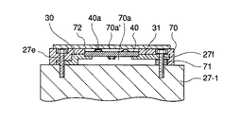
図7は、本発明の第3の実施の形態に係る蓄電式電源装置の構成を示す。図7において、コンデンサセル27−1の上面には、外形がコンデンサセル27−1の平面形状に適合した基板70が載置されている。基板70には、正極端子27e及び負極端子27fの位置に対応して正極端子27e及び負極端子27fの各頭部を収容する孔があけられており、基板70はその下面に電子回路基板40及びバスバー30及び31を収容するような凹部70aを有する。コンデンサ27−1の正極端子27e及び負極端子27hの間において基板70には、電子回路基板40の形状及び大きさに対応する孔70a’があけられている。
【0042】
基板70の孔70a’には電子回路基板40が取付けられている。この電子回路基板40にはその上面及び下面の双方に電子部品40aが実装されている。電子回路基板40の一端にはバスバー30の端部がスポット溶接等により接続されており、電子回路基板40の他端にはバスバー31の端部がスポット溶接等により接続されている。バスバー31は段付きではなく、スペーサ71を介してコンデンサセル27−1に載置されている。
【0043】
それぞれ電極ボルトで構成された正極端子27e及び負極端子27fは、バスバー30,31及び基板70をコンデンサセル27−1に固定する。また、基板70の上面には、正極端子27e及び負極端子27f用の孔並びに孔70a’を閉鎖するカバー72が適宜な手段により取付けられている。本実施の形態によれば、カバー72を外すことにより電子回路40aの保守を容易に行うことができる。
【0044】
図8は、本発明の第4の実施の形態に係る蓄電式電源装置の構成を示す。図8において、コンデンサセル27−1の上面には、外形がコンデンサセル27−1の平面形状に適合した基板80が載置されている。基板80には、正極端子27e及び負極端子27hの位置に対応して正極端子27e及び負極端子27fの各頭部を収容する孔があけられており、基板80はその下面に電子回路基板40及びバスバー30及び31を収容するような凹部80aを有する。コンデンサ27−1の正極端子27e及び負極端子27hの間において基板80の凹部80aには、電子回路基板40の形状及び大きさに対応する孔80a’があけられている。
【0045】
基板80の孔80a’には電子回路基板40が取付けられている。この電子回路基板40にはその下面にのみに電子部品40aが実装されている。電子回路基板40の一端にはバスバー30の端部がスポット溶接等により接続されており、電子回路基板40の他端にはバスバー31の端部がスポット溶接等により接続されている。
【0046】
それぞれ電極ボルトで構成された正極端子27e及び負極端子27fは、バスバー30,31及び基板80をコンデンサセル27−1に固定する。また、基板80の上面には、正極端子27e及び負極端子27fの孔を閉鎖するカバー81がそれぞれ適宜な手段で取付けられている。さらに、電子回路基板40の上面には放熱フィン82が孔80a’を閉鎖するように取付けられている。これにより、電子回路40aが発生する熱を放熱することができ、コンデンサセル27−1の温度上昇を防止することができる。
【0047】
図9は、本発明の第5の実施の形態に係る蓄電式電源装置の構成を示す。図9において、コンデンサセル27−1の上面には、外形がコンデンサセル27−1の平面形状に適合した基板90が載置されている。基板90には、正極端子27e及び負極端子27fの位置に対応して正極端子27e及び負極端子27fの各頭部を収容する孔があけられており、基板90はその下面に電子回路基板40及びバスバー30及び31を収容するような凹部90aを有する。
【0048】
基板90の凹部90aの底部には電子回路基板40が取付けられている。この電子回路基板40にはその下面にのみに電子部品40aが実装されている。電子回路基板40の一端にはバスバー30の端部がスポット溶接等により接続されており、電子回路基板40の他端にはバスバー31の端部がスポット溶接等により接続されている。バスバー31は段付きではなく平板状であり、スペーサ91を介してコンデンサセル27−1上に載置されている。なお、バスバー30もバスバー31と同様に平板状として、スペーサを介してコンデンサセル27−1上に載置されてもよい。
【0049】
それぞれ電極ボルトで構成された正極端子27e及び負極端子27fは、バスバー30,31及び基板90をコンデンサセル27−1に固定する。また、基板90の上面には、正極端子27e及び負極端子27fの孔を閉鎖すると共に上面に放熱用フィンが形成されたカバー92がそれぞれ適宜な手段で取付けられている。これにより、電子回路40aが発生する熱を放熱することができ、コンデンサセル27−1の温度上昇を防止することができる。
【0050】
図10は、本発明の第6の実施の形態に係る蓄電式電源装置の構成を示す。図10において、コンデンサセル27−1の上面には、外形がコンデンサセル27−1の平面形状に適合した基板100が載置されている。基板100には、正極端子27e及び負極端子27fの位置に対応して正極端子27e及び負極端子27fの各頭部を収容する孔があけられており、その下面に電子回路40及びバスバー30及び31を収容するような凹部100aを有する。コンデンサ27−1の正極端子27e及び負極端子27hの間において基板100には、電子回路基板40の形状及び大きさに対応する孔100a’があけられている。
【0051】
基板100の孔100a’には電子回路基板40が取付けられている。この電子回路基板40にはその上面にのみに電子部品40aが実装されている。電子回路基板40の一端にはバスバー30の端部がスポット溶接等により接続されており、電子回路基板40の他端にはバスバー31の端部がスポット溶接等により接続されている。
【0052】
それぞれ電極ボルトで構成された正極端子27e及び負極端子27fは、バスバー30,31及び基板100をコンデンサセル27−1に固定する。また、基板100の上面には、正極端子27e及び負極端子27f用の孔並びに孔100a’を閉鎖するカバー101が適宜な手段により取付けられている。本実施の形態によれば、カバー101を外すことにより電子回路40aの保守を容易に行うことができる。さらに、電子回路基板40の下面には放熱フィン102が取付けられている。これにより、電子回路40aが発生する熱を放熱することができる。
【0053】
以上の説明において、基板60,70,80,90,100の材料は、第1の実施の形態における基板27hと同じであり、バスバー30,31の中間部の形状等は第1の実施の形態と同様に各基板60,70,80,90,100の凹部の底面に当接している(図3(b))。
【0054】
【発明の効果】
以上詳述したように、本発明の請求項1の蓄電式電源装置によれば、複数のコンデンサセルがバスバーを介して直列に接続されたコンデンサブロックと、前記コンデンサセルのそれぞれに接続されており、前記コンデンサセルの作動を制御する電子回路の複数を備える電源装置において、下部に凹部を有する基板が前記コンデンサセルのそれぞれにおける上面に取付けられ、前記バスバーと前記電子回路とは前記凹部の底面に取付けられているので、コンデンサセルの端子と電子回路との間の配線長さ及びバスバーの長さを最短にすることができ、配線のインピーダンスを低減させて蓄電式電源装置のコンデンサセル内の電圧降下を実質的に低減することができ、バスバー及び電子回路のコンデンサセルへの取付構造を簡易化できる。
【0056】
本発明の請求項2の蓄電式電源装置によれば、基板に放熱用フィンが設けられているので、バスバー等の発熱によるコンデンサセルの温度上昇を防止することができる。
【図面の簡単な説明】
【図1】本発明の第1の実施の形態に係る蓄電式電源装置の構成を示すブロック図である。
【図2】図1の蓄電式電源装置におけるコンデンサブロック3の部分平面図である。
【図3】(a)は、図2のA−A’断面図であり、(b)は図2のB−B’断面図である。
【図4】本発明の第1の実施の形態に係る蓄電式電源装置の変形例の概略斜視図である。
【図5】本発明の第1の実施の形態に係る蓄電式電源装置の他の変形例の部分断面図である。
【図6】本発明の第2の実施の形態に係る蓄電式電源装置の断面図である。
【図7】本発明の第3の実施の形態に係る蓄電式電源装置の断面図である。
【図8】本発明の第4の実施の形態に係る蓄電式電源装置の断面図である。
【図9】本発明の第5の実施の形態に係る蓄電式電源装置の断面図である。
【図10】本発明の第6の実施の形態に係る蓄電式電源装置の断面図である。
【符号の説明】
1 蓄電式電源装置
3,4 コンデンサモジュール
7,8 切換スイッチ
11 DC−DCコンバータ
14 PWMドライバ
16 電動モータ
21 コンデンサマネジメントECU
25 モータコントロールECU
26 各種センサ
27,28 コンデンサセル
27a,28a コンデンサ
27h 基板
30,31 バスバー
45,82,102 放熱フィン
60,70,80,90,100 基板
61,72,81,92,101 カバー
71,91 スペーサ[0001]
BACKGROUND OF THE INVENTION
The present invention relates to a power storage device, and more particularly to a power storage device for an electric vehicle.
[0002]
[Prior art]
Conventionally, this type of electric power storage device for an electric vehicle includes at least two capacitor blocks in which a plurality of capacitor cells are connected in series via a bus bar and each of the capacitor cells. A plurality of electronic circuits for controlling the operation of the electronic circuit.
[0003]
Further, in the capacitor block of the power storage type power supply device, the capacitor cells connected in series are of the electric double layer type, the number thereof is about 100, and the voltage of one capacitor cell is 3.5V. Therefore, the voltage when one capacitor block is fully charged is about 350V. This power storage type power supply device is used by switching the connection of two capacitor blocks in parallel or in series according to the remaining capacity of the power supply device, the engine operating state, and the running state of the vehicle.
[0004]
Conventionally, in such a power storage type power supply device, each of the electronic circuits is not provided integrally with the capacitor cell, and is different from the capacitor cell, that is, as a pulse as a motor driver (PDU) as an example. It was installed in the vicinity of a part of the modulation (PWM) driver and the motor.
[0005]
[Problems to be solved by the invention]
As described above, in the conventional power storage device for electric vehicles, each of the electronic circuits is not provided integrally with the capacitor cell, but is provided separately from the capacitor cell. The wiring length between the cell terminal and the electronic circuit is increased, and the impedance of the wiring is increased. As a result, there is a problem that the voltage drop in the capacitor cell of the electricity storage type power supply device is large.
[0006]
An object of the present invention is to reduce the voltage drop in the capacitor cell by reducing the impedance of the wiring between the terminal of the capacitor cell and the electronic circuit, and to provide astructure for mounting the bus bar and the electronic circuit to the capacitor cell. and to provide a Ru power storagedevice can simplified.
[0007]
[Means for Solving the Problems]
In order to achieve the above object, a power storage device according to
[0008]
According to the battery-type power supply unit according to
[0011]
A power storage type power supply device according to asecond aspect is the power storage type power supply device according to thefirst aspect, characterized in that a heat radiating fin is provided on the substrate.
[0012]
According to the electricity storage type power supply device of thesecond aspect , since the heat dissipating fins are provided on the substrate, it is possible to prevent the temperature rise of the capacitor cell due to heat generated by the bus bar or the like.
[0013]
A power storage type power supply device according to athird aspect is the power storage type power supply device according to thefirst orsecond aspect , wherein the substrate is an insulating substrate.
[0014]
A power storage type power supply device according to afourth aspect is characterized in that the power storage type power supply device according to any one of the first tothird aspects is used for an electric vehicle.
[0015]
DETAILED DESCRIPTION OF THE INVENTION
Hereinafter, a power storage type power supply device according to a first embodiment of the present invention will be described with reference to the drawings.
[0016]
FIG. 1 is a block diagram showing a configuration of a power storage type power supply device according to the first embodiment of the present invention.
[0017]
The electric vehicle includes a power storage type
[0018]
The
[0019]
Capacitor blocks 3 and 4 each have 100 V electric double layer
[0020]
The
[0021]
When it is determined that the voltages of the
[0022]
The
[0023]
In addition to the well-known CPU, ROM, RAM, timer, I / O interface, and communication interface, the
[0024]
2 is a partial plan view of the
[0025]
In FIG. 2, a plurality of capacitor cells 27-1 to 27-5 are arranged in the horizontal direction. Each configuration of the capacitor cells 27-1 to 27-5 is the same, and will be described below with a focus on the capacitor cell 27-1.
[0026]
A
[0027]
On the upper surface of the capacitor cell 27-1, the
[0028]
On the upper surface of the capacitor cell 27-1, a
[0029]
Further, as shown in FIG. 3A, an
[0030]
A
[0031]
With the above configuration, since the
[0032]
The
[0033]
According to this embodiment, since the
[0034]
In the embodiment, the
[0035]
FIG. 5 is a partial cross-sectional view of another modification of the power storage type power supply device according to the first embodiment of the present invention. As shown in FIG. 5,
[0036]
Further, as shown in FIG. 5, the intermediate portions of the bus bars 30 and 31 may be fixed to the
[0037]
Hereinafter, a configuration of a power storage type power supply device according to another embodiment of the present invention will be described with reference to the drawings. In the following embodiments, the same components as those of the first embodiment of the present invention are denoted by the same reference numerals, and description thereof is omitted.
[0038]
FIG. 6 shows a configuration of a power storage type power supply device according to the second embodiment of the present invention. In FIG. 6, a
[0039]
An
[0040]
A
[0041]
FIG. 7 shows a configuration of a power storage type power supply device according to the third embodiment of the present invention. In FIG. 7, a
[0042]
An
[0043]
A
[0044]
FIG. 8 shows a configuration of a power storage type power supply device according to the fourth embodiment of the present invention. In FIG. 8, a
[0045]
An
[0046]
A
[0047]
FIG. 9 shows a configuration of a power storage type power supply device according to the fifth embodiment of the present invention. In FIG. 9, a
[0048]
An
[0049]
A
[0050]
FIG. 10 shows a configuration of a power storage type power supply device according to the sixth embodiment of the present invention. In FIG. 10, a
[0051]
An
[0052]
A
[0053]
In the above description, the materials of the
[0054]
【The invention's effect】
As described above in detail, according to the power storage type power supply device of
[0056]
According to the power storage type power supply device of claim2 of the present invention, since the heat dissipating fins are provided on the substrate, it is possible to prevent the temperature rise of the capacitor cell due to heat generation of the bus bar or the like.
[Brief description of the drawings]
FIG. 1 is a block diagram showing a configuration of a power storage type power supply device according to a first embodiment of the present invention.
2 is a partial plan view of a
3A is a cross-sectional view taken along the line AA ′ in FIG. 2, and FIG. 3B is a cross-sectional view taken along the line BB ′ in FIG.
FIG. 4 is a schematic perspective view of a modified example of the power storage type power supply device according to the first embodiment of the present invention.
FIG. 5 is a partial cross-sectional view of another modified example of the power storage type power supply device according to the first embodiment of the present invention.
FIG. 6 is a cross-sectional view of a power storage type power supply device according to a second embodiment of the present invention.
FIG. 7 is a cross-sectional view of a power storage type power supply device according to a third embodiment of the present invention.
FIG. 8 is a cross-sectional view of a power storage type power supply device according to a fourth embodiment of the present invention.
FIG. 9 is a cross-sectional view of a power storage type power supply device according to a fifth embodiment of the present invention.
FIG. 10 is a cross-sectional view of a power storage type power supply device according to a sixth embodiment of the present invention.
[Explanation of symbols]
DESCRIPTION OF
25 Motor control ECU
26
Claims (4)
Translated fromJapanesePriority Applications (2)
| Application Number | Priority Date | Filing Date | Title |
|---|---|---|---|
| JP27862096AJP3637163B2 (en) | 1996-10-01 | 1996-10-01 | Energy storage power supply |
| US08/941,503US5880951A (en) | 1996-10-01 | 1997-09-30 | Capacitor-type power supply unit |
Applications Claiming Priority (1)
| Application Number | Priority Date | Filing Date | Title |
|---|---|---|---|
| JP27862096AJP3637163B2 (en) | 1996-10-01 | 1996-10-01 | Energy storage power supply |
Publications (2)
| Publication Number | Publication Date |
|---|---|
| JPH10108361A JPH10108361A (en) | 1998-04-24 |
| JP3637163B2true JP3637163B2 (en) | 2005-04-13 |
Family
ID=17599822
Family Applications (1)
| Application Number | Title | Priority Date | Filing Date |
|---|---|---|---|
| JP27862096AExpired - Fee RelatedJP3637163B2 (en) | 1996-10-01 | 1996-10-01 | Energy storage power supply |
Country Status (2)
| Country | Link |
|---|---|
| US (1) | US5880951A (en) |
| JP (1) | JP3637163B2 (en) |
Cited By (1)
| Publication number | Priority date | Publication date | Assignee | Title |
|---|---|---|---|---|
| CN111361765A (en)* | 2020-03-19 | 2020-07-03 | 上海卫星工程研究所 | Spacecraft power supply double-bus system |
Families Citing this family (38)
| Publication number | Priority date | Publication date | Assignee | Title |
|---|---|---|---|---|
| JP3345318B2 (en)* | 1997-10-17 | 2002-11-18 | 株式会社岡村研究所 | Capacitor power storage device |
| DE19847029A1 (en)* | 1998-10-13 | 2000-04-27 | Semikron Elektronik Gmbh | Converter with low-inductance capacitor in the intermediate circuit |
| JP2000184508A (en)* | 1998-12-18 | 2000-06-30 | Nissan Diesel Motor Co Ltd | Hibrid drive system of vehicle |
| US7175644B2 (en)* | 2001-02-14 | 2007-02-13 | Broncus Technologies, Inc. | Devices and methods for maintaining collateral channels in tissue |
| TW200409153A (en)* | 2002-09-04 | 2004-06-01 | Nec Corp | Strip line element, printed circuit board carrying member, circuit board, semiconductor package and method for forming same |
| US7203056B2 (en)* | 2003-11-07 | 2007-04-10 | Maxwell Technologies, Inc. | Thermal interconnection for capacitor systems |
| US7180726B2 (en)* | 2003-11-07 | 2007-02-20 | Maxwell Technologies, Inc. | Self-supporting capacitor structure |
| US7440258B2 (en) | 2005-03-14 | 2008-10-21 | Maxwell Technologies, Inc. | Thermal interconnects for coupling energy storage devices |
| DE102005018339A1 (en)* | 2005-04-20 | 2006-10-26 | Siemens Ag | Arrangement with a capacitor module and method for its operation |
| DE102005023486B4 (en)* | 2005-05-21 | 2007-05-10 | Diehl Aerospace Gmbh | Apparatus and method for monitoring and controlling multiple series connected capacities |
| US7915854B2 (en)* | 2005-12-16 | 2011-03-29 | Plug Power Inc. | Maximizing energy storage life in a fuel cell system using active temperature compensation |
| DE102006036425A1 (en)* | 2006-08-04 | 2008-02-07 | Bayerische Motoren Werke Ag | System for supplying power to electrical consumers of a motor vehicle |
| DE102006036424A1 (en)* | 2006-08-04 | 2008-02-07 | Bayerische Motoren Werke Ag | System for supplying power to electrical consumers of a motor vehicle using a supercap |
| JP5130870B2 (en)* | 2007-11-12 | 2013-01-30 | 株式会社安川電機 | Motor control device |
| TW201019091A (en)* | 2008-11-06 | 2010-05-16 | Chien-Chiang Chan | Power supply module |
| DE102008062657A1 (en)* | 2008-12-04 | 2010-06-10 | Stribel Production Gmbh | Energy storage device |
| DE102009002202A1 (en) | 2009-04-06 | 2010-10-14 | Beckhoff Automation Gmbh | Circuit and method for the uninterruptible power supply of electronic assemblies |
| JP5439099B2 (en) | 2009-09-16 | 2014-03-12 | Udトラックス株式会社 | Power storage device and power storage module |
| JP5534352B2 (en)* | 2011-03-31 | 2014-06-25 | アイシン・エィ・ダブリュ株式会社 | Inverter device |
| JP5694843B2 (en)* | 2011-04-25 | 2015-04-01 | Jmエナジー株式会社 | Power storage module |
| DE102012001390A1 (en)* | 2012-01-26 | 2013-08-01 | Sew-Eurodrive Gmbh & Co. Kg | Energy storage unit e.g. battery, has subsets whose terminals are fed in connecting elements that comprise electrical interconnections, where interconnections are connectable such that voltage or capacitance are adjustable from terminals |
| US9653720B2 (en) | 2013-12-19 | 2017-05-16 | Ford Global Technologies, Llc | Traction battery assembly |
| US10340082B2 (en) | 2015-05-12 | 2019-07-02 | Capacitor Sciences Incorporated | Capacitor and method of production thereof |
| US10347423B2 (en) | 2014-05-12 | 2019-07-09 | Capacitor Sciences Incorporated | Solid multilayer structure as semiproduct for meta-capacitor |
| JP6953306B2 (en) | 2014-05-12 | 2021-10-27 | キャパシター サイエンシズ インコーポレイテッドCapacitor Sciences Incorporated | Energy storage device and its manufacturing method |
| US9916931B2 (en) | 2014-11-04 | 2018-03-13 | Capacitor Science Incorporated | Energy storage devices and methods of production thereof |
| SG11201706689QA (en) | 2015-02-26 | 2017-09-28 | Capacitor Sciences Inc | Self-healing capacitor and methods of production thereof |
| US9932358B2 (en) | 2015-05-21 | 2018-04-03 | Capacitor Science Incorporated | Energy storage molecular material, crystal dielectric layer and capacitor |
| US9941051B2 (en) | 2015-06-26 | 2018-04-10 | Capactor Sciences Incorporated | Coiled capacitor |
| JP6350418B2 (en)* | 2015-06-30 | 2018-07-04 | トヨタ自動車株式会社 | Charging device and discharging device |
| FR3039313B1 (en)* | 2015-07-23 | 2019-07-26 | Blue Solutions | RECONFIGURABLE CAPACITIVE EFFICIENT ENERGY STORAGE DEVICE, POWER SUPPLY SYSTEM AND ELECTRIC VEHICLE INCORPORATING SAID DEVICE |
| US10026553B2 (en) | 2015-10-21 | 2018-07-17 | Capacitor Sciences Incorporated | Organic compound, crystal dielectric layer and capacitor |
| US10305295B2 (en) | 2016-02-12 | 2019-05-28 | Capacitor Sciences Incorporated | Energy storage cell, capacitive energy storage module, and capacitive energy storage system |
| US9978517B2 (en) | 2016-04-04 | 2018-05-22 | Capacitor Sciences Incorporated | Electro-polarizable compound and capacitor |
| US10153087B2 (en) | 2016-04-04 | 2018-12-11 | Capacitor Sciences Incorporated | Electro-polarizable compound and capacitor |
| US10395841B2 (en) | 2016-12-02 | 2019-08-27 | Capacitor Sciences Incorporated | Multilayered electrode and film energy storage device |
| KR102547273B1 (en)* | 2019-04-25 | 2023-06-23 | 엘에스머트리얼즈 주식회사 | Ultra capacitor and assembly for connecting the same |
| CN114902465B (en)* | 2019-10-16 | 2025-05-27 | 循环充电控股有限公司 | Electronic components |
Family Cites Families (6)
| Publication number | Priority date | Publication date | Assignee | Title |
|---|---|---|---|---|
| FR2232825B1 (en)* | 1973-06-07 | 1978-06-30 | Sic Safco Condensateurs | |
| US4292665A (en)* | 1978-05-23 | 1981-09-29 | Lh Research | Output stage for switching regulated power supply |
| DE4005333A1 (en)* | 1990-02-20 | 1991-08-22 | Rehm Schweisstechnik Gmbh | ELECTRONIC CIRCUIT BREAKER |
| GB2242580B (en)* | 1990-03-30 | 1994-06-15 | Mitsubishi Electric Corp | Inverter unit with improved bus-plate configuration |
| JP2809095B2 (en)* | 1994-03-04 | 1998-10-08 | 株式会社デンソー | Inverter device |
| US5713426A (en)* | 1996-03-19 | 1998-02-03 | Jeol Ltd. | Hybrid vehicle |
- 1996
- 1996-10-01JPJP27862096Apatent/JP3637163B2/ennot_activeExpired - Fee Related
- 1997
- 1997-09-30USUS08/941,503patent/US5880951A/ennot_activeExpired - Fee Related
Cited By (1)
| Publication number | Priority date | Publication date | Assignee | Title |
|---|---|---|---|---|
| CN111361765A (en)* | 2020-03-19 | 2020-07-03 | 上海卫星工程研究所 | Spacecraft power supply double-bus system |
Also Published As
| Publication number | Publication date |
|---|---|
| JPH10108361A (en) | 1998-04-24 |
| US5880951A (en) | 1999-03-09 |
Similar Documents
| Publication | Publication Date | Title |
|---|---|---|
| JP3637163B2 (en) | Energy storage power supply | |
| JP5228076B2 (en) | In-vehicle power storage device | |
| KR100891430B1 (en) | Hybrid car inverter | |
| US6843335B2 (en) | Power conversion apparatus and mobile object incorporating thereof | |
| JP5250297B2 (en) | Power converter | |
| JP4038899B2 (en) | Inverter with built-in capacitor for power smoothing | |
| US9543551B2 (en) | Lightweight and rigid structure of battery unit | |
| US20140239904A1 (en) | Compact structure of battery unit | |
| KR20100117505A (en) | Battery module, battery system and electric vehicle | |
| JP5530884B2 (en) | Power storage device | |
| JP6720847B2 (en) | Battery pack | |
| JP4313273B2 (en) | Power drive unit | |
| CN108140496B (en) | storage unit | |
| JP2018190607A (en) | Battery pack | |
| US20230347746A1 (en) | Power distribution device | |
| JP2012105373A (en) | Power converter | |
| JP2016222057A (en) | Vehicle power supply | |
| JP4487962B2 (en) | Inverter device | |
| US12154739B2 (en) | Power distribution device | |
| CN119422268A (en) | Structural component with heat-conducting plate for an electrical energy store | |
| JP6805792B2 (en) | Battery pack | |
| WO2022113630A1 (en) | Power conversion device | |
| CN115275492B (en) | Traction batteries for motor vehicles | |
| US20250164317A1 (en) | Temperature measuring system for power semiconductors arranged on a base plate of an inverter | |
| JP7409271B2 (en) | power converter |
Legal Events
| Date | Code | Title | Description |
|---|---|---|---|
| A977 | Report on retrieval | Free format text:JAPANESE INTERMEDIATE CODE: A971007 Effective date:20040623 | |
| A131 | Notification of reasons for refusal | Free format text:JAPANESE INTERMEDIATE CODE: A131 Effective date:20040629 | |
| A521 | Request for written amendment filed | Free format text:JAPANESE INTERMEDIATE CODE: A523 Effective date:20040826 | |
| TRDD | Decision of grant or rejection written | ||
| A01 | Written decision to grant a patent or to grant a registration (utility model) | Free format text:JAPANESE INTERMEDIATE CODE: A01 Effective date:20041222 | |
| A61 | First payment of annual fees (during grant procedure) | Free format text:JAPANESE INTERMEDIATE CODE: A61 Effective date:20050107 | |
| R150 | Certificate of patent or registration of utility model | Free format text:JAPANESE INTERMEDIATE CODE: R150 | |
| FPAY | Renewal fee payment (event date is renewal date of database) | Free format text:PAYMENT UNTIL: 20080114 Year of fee payment:3 | |
| FPAY | Renewal fee payment (event date is renewal date of database) | Free format text:PAYMENT UNTIL: 20090114 Year of fee payment:4 | |
| FPAY | Renewal fee payment (event date is renewal date of database) | Free format text:PAYMENT UNTIL: 20100114 Year of fee payment:5 | |
| FPAY | Renewal fee payment (event date is renewal date of database) | Free format text:PAYMENT UNTIL: 20100114 Year of fee payment:5 | |
| FPAY | Renewal fee payment (event date is renewal date of database) | Free format text:PAYMENT UNTIL: 20110114 Year of fee payment:6 | |
| LAPS | Cancellation because of no payment of annual fees |