JP3637039B2 - Hydrogen gas generation method and hydrogen gas generator - Google Patents
Hydrogen gas generation method and hydrogen gas generatorDownload PDFInfo
- Publication number
- JP3637039B2 JP3637039B2JP2002218552AJP2002218552AJP3637039B2JP 3637039 B2JP3637039 B2JP 3637039B2JP 2002218552 AJP2002218552 AJP 2002218552AJP 2002218552 AJP2002218552 AJP 2002218552AJP 3637039 B2JP3637039 B2JP 3637039B2
- Authority
- JP
- Japan
- Prior art keywords
- hydrogen gas
- aqueous solution
- cathode
- voltage
- less
- Prior art date
- Legal status (The legal status is an assumption and is not a legal conclusion. Google has not performed a legal analysis and makes no representation as to the accuracy of the status listed.)
- Expired - Fee Related
Links
Images

Classifications
- Y—GENERAL TAGGING OF NEW TECHNOLOGICAL DEVELOPMENTS; GENERAL TAGGING OF CROSS-SECTIONAL TECHNOLOGIES SPANNING OVER SEVERAL SECTIONS OF THE IPC; TECHNICAL SUBJECTS COVERED BY FORMER USPC CROSS-REFERENCE ART COLLECTIONS [XRACs] AND DIGESTS
- Y02—TECHNOLOGIES OR APPLICATIONS FOR MITIGATION OR ADAPTATION AGAINST CLIMATE CHANGE
- Y02E—REDUCTION OF GREENHOUSE GAS [GHG] EMISSIONS, RELATED TO ENERGY GENERATION, TRANSMISSION OR DISTRIBUTION
- Y02E60/00—Enabling technologies; Technologies with a potential or indirect contribution to GHG emissions mitigation
- Y02E60/30—Hydrogen technology
- Y02E60/36—Hydrogen production from non-carbon containing sources, e.g. by water electrolysis
Landscapes
- Electrodes For Compound Or Non-Metal Manufacture (AREA)
- Electrolytic Production Of Non-Metals, Compounds, Apparatuses Therefor (AREA)
Description
Translated fromJapanese【0001】
【発明の属する技術分野】
本発明は、水素ガスの発生方法および発生装置に係り、特に、水溶液の直接熱分解により常圧下で連続的に水素ガスを発生する技術に関する。
【0002】
【従来の技術】
従来から水素源としては、石炭や石油といった化石燃料を原料とした水素源、原子力、および自然エネルギーをエネルギーとした電解水素などが知られている。これらのうち、化石燃料は資源量枯渇が懸念されるのみならず、炭酸ガスなどの地球温暖化の原因ともなり、原子力は放射性廃棄物が生じるという問題を有している。自然エネルギーとしては、太陽発電、風力発電、および地熱などが挙げられるが、これらはコストや自然条件に左右される。
【0003】
電解では十分な効率を得ることができず、コストや耐久性に問題があった。電解による水の分解には、室温で242kJ/molが必要であり、この際の直接熱による反応は、13kJ/molしか寄与していない。
【0004】
また、化石燃料や水から水素を直接熱分解によって取り出すには、数100℃、数10〜数100気圧の高温高圧の条件が必要とされる(特開平9−188501号公報)。
【0005】
完全に熱のみで水を分解するためには、4000℃以上という著しく高い温度で行なわなければならず、このときの分解熱としては、255kJ/mol必要になる。こうした条件を実現するのは極めて困難であり、直接熱分解は実用には向かなかった。
【0006】
【発明が解決しようとする課題】
そこで本発明は、制御性よく、連続的に水を直接熱分解して、高い効率で水素ガスを発生する方法を提供することを目的とする。
【0007】
また本発明は、制御性よく、連続的に水の直接熱分解により高い効率で水素ガスを発生し得る装置を提供することを目的とする。
【0008】
【課題を解決するための手段】
上記課題を解決するために、本発明の一態様は、反応容器内に、炭酸カリウムおよび炭酸ナトリウムからなる群から選択される少なくとも1種のアルカリ金属炭酸塩を、0.05モル以上5モル以下の濃度で含有する金属塩の水溶液を収容し、70℃以上100℃未満に加熱する工程、
前記加熱された水溶液に100V以上2000V以下の電圧を、0.1s以上10s以下のパルス幅、0.01s以上5s以下のパルス間隔で印加してプラズマを発生させる工程、および
前記プラズマにより前記水溶液を電気分解する工程
を具備することを特徴とする水素ガスの発生方法を提供する。
【0009】
また本発明の他の態様は、酸、アルカリまたは金属塩の水溶液を収容した反応容器と、
前記反応容器の周囲に配置され、前記水溶液を加熱する加熱手段と、
前記水溶液中に浸漬された高融点金属からなる棒状の陰極と、
前記陰極を取り囲んで配置された白金からなるリング状の陽極と、
前記陰極および陽極に電圧を印加するための電源と、
前記電圧を周期的に制御する電圧制御手段と
を具備することを特徴とする水素ガス発生装置を提供する。
【0010】
【発明の実施の形態】
以下、本発明の実施形態を詳細に説明する。
【0011】
本発明に係る水素ガス発生装置の一例の構成を図1に示す。
【0012】
図1に示される水素ガス発生装置は、液補給口12、液出口13、水素ガス出口14、酸素ガス出口15、および圧力の調整弁(図示せず)を有し、閉鎖された反応容器1、この反応容器の周囲に配置された加熱手段としての熱交換器3を具備し、反応容器1内には水溶液2が収容される。この水溶液中には、棒状の陰極4および陰極を取り囲むリング状の陽極5が、隔壁6により隔てられて浸漬される。陰極4の陰極端子7および陽極5の陽極端子8は、電圧制御手段10を介して電源9に接続される。
【0013】
なお、陰極4は、高温に耐える絶縁物、例えばアルミナなどのセラミックスからなる陰極被覆材11により側面が被覆され、下方端部が所定の長さだけ露出している。
【0014】
反応容器1は、例えば金属(ステンレスSS304)製とすることができ、その内面は、水溶液との接触を避けるためにテフロン(登録商標)被覆が施されている。発生したガスと反応容器の金属との接触を避けるために、同様のテフロン被覆が、水素ガス出口14および酸素ガス出口15の周囲や内部にも施されている。ただし、反応は高温で行なわれるため水蒸気が混合しており、活性な白金属元素が存在しない場合には、急激な燃焼反応が生じるおそれはない。
【0015】
水溶液2としては、酸、アルカリ、または金属塩類が用いられる。酸としては、例えば硫酸等が挙げられ、アルカリとしては、例えば水酸化カリウムおよび水酸化ナトリウム等が挙げられる。また、金属塩としては、例えば炭酸カリウム、炭酸ナトリウム、および炭酸リチウムのようなアルカリ金属炭酸塩等が挙げられる。制御性、発熱量、電極の保存性、および安全性や廃棄後の処理性等の点から、特に炭酸カリウムおよび炭酸ナトリウムが最適である。
【0016】
水溶液中におけるアルカリ炭酸塩の濃度は、0.05モル以上5モル以下程度とすることが好ましい。0.05モル未満の場合には、プラズマ電解が困難となり、一方、5モルを越えると電極の消耗が激しくなるおそれがある。アルカリ炭酸塩の濃度は、0.1モル以上であることがより好ましい。
【0017】
反応容器1中に収容される水溶液2の量は、用いられる電極の形状や配置に応じて適宜決定することができる。例えば、1cc/sの水素ガスを得るためには、1cm2の電極面積と0.1kWの入力とが必要となる。この場合に必要な溶液量は、1000cm3と算出される。
【0018】
陰極4は、長時間、高温の溶液中で使用に耐え、安定した電解特性を示す材料、具体的には、タングステン、白金、タンタル、ニオブ、およびモリブデン等の高融点金属から構成される棒状の電極である。あるいは、ジルコニウム、ニッケル、パラジウム等の水素高活性電極金属製の棒を陰極として用いてもよい。
【0019】
陰極4の直径は、0.1cm以上1cm以下程度とすることが好ましく、1mm以上5mm程度以下であることがより好ましい。直径が0.1cm未満の場合には、電極の消耗が激しく耐久性が乏しくなるおそれがあり、一方、1cmを越えると、高温のプラズマを得るのが困難という不都合が生じる。陰極4は反応により消耗するので、必要に応じて水溶液中にさらに底部まで浸漬できるよう、ネジ等を用いて反応容器1に固定されていることが望まれる。
【0020】
上述したような陰極4の周囲を取り囲んで、リング状の陽極5が配置される。こうした電極配置によって、均一な電場が形成され、反応を持続させることができる。陽極5は白金から構成され、その面積は陰極4の面積の10倍以上であることが好ましい。陽極5の面積をこのように大きくすることは、プラズマ形成の点で有利である。なお、陽極の面積は、陰極の面積の100倍以上であることがより好ましい。陰極からの距離は、反応容器1の大きさに応じて適宜選択できるが、通常、数cm程度である。
【0021】
本発明の実施形態にかかる閉鎖型の反応容器は、系を高温に保って反応を加速させることができ、プラズマ電解により効率よく水素ガスを取り出すことが可能である。
【0022】
図1に示した装置を用いて水素ガスを発生させるに当たっては、まず、熱交換器3により水溶液2の温度を70℃以上100℃未満に上昇させる。場合によっては、水の電気分解による発熱により昇温することもできる。プラズマ電解時の水溶液の温度は高い方が望ましいので、70℃以上に加熱することが必要であり、常圧で液体を維持するために、水溶液の温度は100℃未満に制限される。加熱温度は80℃以上90℃以下とすることが好ましい。
【0023】
次いで、電源9から陰極端子7および陽極端子8に電圧を印加して、プラズマ電解を開始する。印加される電圧は、水溶液や電極材料の種類、反応容器内における電極の配置によって異なるが、基本的に120V前後から始める。流れる電流は、電極面積の大きさに応じて変化し、定電圧で行なわれるため系の条件により決定される。通常は、放電電解初期には4〜5A/cm2の電流が流れ、その後、温度の上昇とともに1A/cm2程度に減少する。この操作によって、陰極4近傍で強い加熱が始まって、発熱および発光が生じる。
【0024】
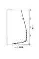
プラズマ電解における電流と電圧との関係を、図2のグラフに示す。
【0025】
水溶液2中に浸漬された陰極4と陽極5との間に電流を流して電圧を上げるにしたがって、陽極5に酸素ガスが発生し、一方の陰極4には水素ガスが発生して通常の電解が行なわれる。これは、図2のグラフにおけるaとbとの間の領域に相当し、電圧を上げるとガスの発生は次第に激しくなって、周期的に水素ガスと蒸気とが発生する。回路電流は激しく変動し、陰極と水溶液との間で音が発生して、ついにb点では火花が発生する。さらに電流を増そうとしても増加することなく、電圧は増加しても電流密度は減少する。bc間では、制御は困難となって自動的にc点に移動する。さらに電圧を増加させると電流変動は抑制され、次第に電流は増加して、ついにはアーク放電に移行する(d点)。
【0026】
発熱の制御は、cd点の間で、電場強度(100〜2000V)および周波数を変化させることによって行なわれる。具体的には、矩形波を使用し、その波形波高を変化させて制御する。矩形波を使用せずに直流の電圧で放電を継続した場合には、電極の消耗が極めて激しくなり、長時間の放電は困難である。このために、プラズマが電極の回りに形成された後は、矩形波制御によって連続的に水素ガスを取り出すことができる。陽極から発生した酸素は、酸素ガス出口15から回収され、直接熱分解により発生した(水素+酸素)の混合気体は、水素ガスとともに水素過剰な混合物として水素ガス出口14から回収される。
【0027】
プラズマを発生する際の電圧は100V以上2000V以下に規定され、200V以上1500V以下とすることが好ましい。電圧が100V未満の場合には、プラズマは形成されず通常の電気分解となるため、水の熱分解は困難となり、一方、2000Vを越えると直接アーク放電となって、電極の回りにプラズマは形成されずに電極が破壊されるおそれがある。
【0028】
矩形波のパルス幅は0.1s以上10s以下であり、パルス間隔は0.01s以上5s以下に規定される。パルス幅が0.1s未満の場合には、単発放電と同じ状態となってプラズマの維持が困難となり、一方、10sを越えた場合には、連続放電に近く電極が損耗するおそれがある。また、パルス間隔が0.01s未満の場合には、連続放電となり電極の維持が困難となり、一方、5sを越えると、プラズマの形成が難しく水素ガスが得られないおそれがある。
【0029】
【実施例】
以下、具体例を示して本発明をさらに詳細に説明する。
【0030】
(実施例1)
図1に示した反応容器に、炭酸カリウムを0.2モルの濃度で含有する水溶液を1000cc収容し、水溶液の直接熱分解により水素ガスを発生させた。陰極としては、太さ1.5mm、長さ4cmのタングステン製の棒を用いた。陽極としてのリング状の白金製電極の面積は、陰極の面積の10倍程度とし、水溶液の温度は85℃とした。
【0031】
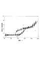
この際の電圧と水素ガス発生効率(比率ε)との関系を図3のグラフに示す。水素ガス発生効率は、水素ガス発生量の測定値を入力電流値からの算出値で除した値である。
【0032】
εが1であれば、ファラデーの法則にしたがって1Fで0.5モルの水素ガスが発生したことになる。電解に当たっては、10Vから10Vごとに電圧を上昇させた。放電電解は150Vから開始し、110Vの段階ですでにεは1を越えていることがわかる。εの値は電圧を上げるにしたがって増加し、150Vの時点では4.3になっている。150〜200Vまでにεは5になるが、その後、電圧の上昇につれて、230Vでは7になる。
【0033】
電圧を低下させて60V以下に戻したところ、通常の電気分解となって過剰な水素発生は停止した。
【0034】
(実施例2)
陰極の長さを5cmに変更し、水溶液の温度を90℃とした以外は、前述の実施例1と同様の条件で水素ガスを発生させた。その結果、より大量の水素が得られ、放電開始後、直ちに過剰水素が放出され始めた。電圧の上昇とともに過剰水素は増大して、230Vでは10以上のε値が得られた。
【0035】
(実施例3)
陰極の長さを5cmに変更し、水溶液の温度を95℃にした以外は、前述の実施例1と同様の条件で水素ガスを発生させた。その結果、250Vでεは100の値が得られた。
【0036】
【発明の効果】
以上詳述したように、本発明の一態様によれば、制御性よく、連続的に水を直接熱分解して、高い効率で水素ガスを発生する方法が提供される。また、本発明の他の態様によれば、制御性よく、連続的に水の直接熱分解により高い効率で水素ガスを発生し得る装置が提供される。
【0037】
本発明により、従来の水素ガス発生方法における問題点を全て解決することができ、その工業的価値は絶大である。
【図面の簡単な説明】
【図1】本発明の一実施形態にかかる水素ガス発生装置の構成を示す概略図。
【図2】プラズマ電解における電圧と電流密度との関係を表わすグラフ図。
【図3】電圧と水素ガス発生効率との関係を表わすグラフ図。
【符号の説明】
1…反応容器
2…水溶液
3…熱交換器
4…陰極
5…陽極
6…隔壁
7…陰極端子
8…陽極端子
9…電源
10…電圧制御手段
11…陰極被覆材
12…液補給口
13…液出口
14…水素ガス出口
15…酸素ガス出口[0001]
BACKGROUND OF THE INVENTION
The present invention relates to a method and an apparatus for generating hydrogen gas, and more particularly to a technique for generating hydrogen gas continuously under normal pressure by direct thermal decomposition of an aqueous solution.
[0002]
[Prior art]
Conventionally known hydrogen sources include hydrogen sources using fossil fuels such as coal and petroleum, nuclear power, and electrolytic hydrogen using natural energy as energy. Of these, fossil fuels are not only concerned about resource depletion, but also cause global warming such as carbon dioxide, and nuclear power has the problem that radioactive waste is generated. Examples of natural energy include solar power generation, wind power generation, and geothermal heat, but these depend on cost and natural conditions.
[0003]
In electrolysis, sufficient efficiency cannot be obtained, and there are problems in cost and durability. The decomposition of water by electrolysis requires 242 kJ / mol at room temperature, and the reaction by direct heat at this time contributes only 13 kJ / mol.
[0004]
Further, in order to take out hydrogen from fossil fuel or water directly by thermal decomposition, high temperature and high pressure conditions of several hundreds of degrees Celsius and several tens to several hundreds of atmospheres are required (Japanese Patent Laid-Open No. 9-188501).
[0005]
In order to completely decompose water only with heat, it must be performed at a remarkably high temperature of 4000 ° C. or higher, and the heat of decomposition at this time requires 255 kJ / mol. It is extremely difficult to realize such conditions, and direct pyrolysis is not suitable for practical use.
[0006]
[Problems to be solved by the invention]
Accordingly, an object of the present invention is to provide a method for generating hydrogen gas with high efficiency by directly thermally decomposing water with good controllability.
[0007]
Another object of the present invention is to provide an apparatus capable of generating hydrogen gas with high controllability and continuously by direct thermal decomposition of water with high efficiency.
[0008]
[Means for Solving the Problems]
In order to solve the above problems, according to one embodiment of the present invention, 0.05 mol or more and 5 mol or less of at least one alkali metal carbonate selected from the group consisting of potassium carbonate and sodium carbonate is contained in a reaction vessel.Containing an aqueous solution ofa metal saltcontained at a concentration of 70 ° C. or more and less than 100 ° C.,
Applying a voltage of 100 V to 2000 V to the heated aqueous solution at a pulse width of 0.1 s to 10 s and a pulse interval of 0.01 s to 5 s to generate plasma; and Provided is a method for generating hydrogen gas, comprising a step of electrolysis.
[0009]
In another aspect of the present invention, a reaction vessel containing an aqueous solution of an acid, alkali or metal salt;
A heating means disposed around the reaction vessel for heating the aqueous solution;
A rod-shaped cathode made of a refractory metal immersed in the aqueous solution;
A ring-shaped anode made of platinum disposed around the cathode; and
A power supply for applying a voltage to the cathode and anode;
A hydrogen gas generator comprising a voltage control means for periodically controlling the voltage is provided.
[0010]
DETAILED DESCRIPTION OF THE INVENTION
Hereinafter, embodiments of the present invention will be described in detail.
[0011]
The configuration of an example of a hydrogen gas generator according to the present invention is shown in FIG.
[0012]
The hydrogen gas generator shown in FIG. 1 has a
[0013]
The cathode 4 has a side surface covered with a cathode coating material 11 made of an insulating material that can withstand high temperatures, for example, ceramics such as alumina, and a lower end portion is exposed for a predetermined length.
[0014]
The reaction vessel 1 can be made of, for example, metal (stainless steel SS304), and its inner surface is coated with Teflon (registered trademark) to avoid contact with an aqueous solution. In order to avoid contact between the generated gas and the metal in the reaction vessel, the same Teflon coating is also provided around and inside the
[0015]
As the
[0016]
The concentration of the alkali carbonate in the aqueous solution is preferably about 0.05 mol to 5 mol. When the amount is less than 0.05 mol, plasma electrolysis becomes difficult. On the other hand, when the amount exceeds 5 mol, there is a risk that the consumption of the electrode becomes severe. The concentration of the alkali carbonate is more preferably 0.1 mol or more.
[0017]
The amount of the
[0018]
The cathode 4 is a rod-like material composed of a high-melting-point metal such as tungsten, platinum, tantalum, niobium, and molybdenum that can withstand use in a high-temperature solution for a long time and exhibits stable electrolytic characteristics. Electrode. Alternatively, a high-activity electrode metal rod such as zirconium, nickel, or palladium may be used as the cathode.
[0019]
The diameter of the cathode 4 is preferably about 0.1 cm to 1 cm, and more preferably about 1 mm to 5 mm. If the diameter is less than 0.1 cm, the electrode may be worn out and the durability may be poor. On the other hand, if it exceeds 1 cm, it is difficult to obtain high-temperature plasma. Since the cathode 4 is consumed by the reaction, it is desirable that the cathode 4 be fixed to the reaction vessel 1 using screws or the like so that it can be further immersed in the aqueous solution to the bottom as required.
[0020]
A ring-shaped
[0021]
The closed reaction container according to the embodiment of the present invention can accelerate the reaction while keeping the system at a high temperature, and can efficiently extract hydrogen gas by plasma electrolysis.
[0022]
In generating hydrogen gas using the apparatus shown in FIG. 1, first, the temperature of the
[0023]
Next, a voltage is applied from the
[0024]
The relationship between current and voltage in plasma electrolysis is shown in the graph of FIG.
[0025]
As current is passed between the cathode 4 and the
[0026]
Heat generation is controlled by changing the electric field strength (100 to 2000 V) and frequency between the cd points. Specifically, a rectangular wave is used, and the waveform wave height is changed and controlled. When the discharge is continued with a DC voltage without using the rectangular wave, the electrode is extremely consumed and it is difficult to discharge for a long time. For this reason, after the plasma is formed around the electrodes, hydrogen gas can be continuously extracted by rectangular wave control. Oxygen generated from the anode is recovered from the
[0027]
The voltage at the time of generating plasma is defined as 100 V or more and 2000 V or less, and preferably 200 V or more and 1500 V or less. When the voltage is less than 100 V, plasma is not formed and normal electrolysis is performed, so that thermal decomposition of water becomes difficult. On the other hand, when the voltage exceeds 2000 V, direct arc discharge occurs, and plasma is formed around the electrodes. Otherwise, the electrode may be destroyed.
[0028]
The pulse width of the rectangular wave is 0.1 s to 10 s, and the pulse interval is defined to be 0.01 s to 5 s. When the pulse width is less than 0.1 s, it becomes difficult to maintain the plasma in the same state as single discharge, while when it exceeds 10 s, there is a possibility that the electrode is worn close to continuous discharge. Further, when the pulse interval is less than 0.01 s, it becomes difficult to maintain the electrode because of continuous discharge. On the other hand, when it exceeds 5 s, it is difficult to form plasma and hydrogen gas may not be obtained.
[0029]
【Example】
Hereinafter, the present invention will be described in more detail with reference to specific examples.
[0030]
(Example 1)
In the reaction vessel shown in FIG. 1, 1000 cc of an aqueous solution containing potassium carbonate at a concentration of 0.2 mol was accommodated, and hydrogen gas was generated by direct thermal decomposition of the aqueous solution. As the cathode, a tungsten rod having a thickness of 1.5 mm and a length of 4 cm was used. The area of the ring-shaped platinum electrode as the anode was about 10 times the area of the cathode, and the temperature of the aqueous solution was 85 ° C.
[0031]
The relationship between the voltage and the hydrogen gas generation efficiency (ratio ε) at this time is shown in the graph of FIG. The hydrogen gas generation efficiency is a value obtained by dividing the measured value of the hydrogen gas generation amount by the calculated value from the input current value.
[0032]
If ε is 1, it means that 0.5 mol of hydrogen gas was generated at 1F according to Faraday's law. In electrolysis, the voltage was increased every 10V to 10V. It can be seen that the discharge electrolysis starts at 150V and ε has already exceeded 1 at the 110V stage. The value of ε increases as the voltage is increased, and is 4.3 at the time of 150V. Ε becomes 5 by 150 to 200V, but then becomes 7 at 230V as the voltage increases.
[0033]
When the voltage was lowered to 60 V or less, the electrolysis became normal and excessive hydrogen generation stopped.
[0034]
(Example 2)
Hydrogen gas was generated under the same conditions as in Example 1 except that the length of the cathode was changed to 5 cm and the temperature of the aqueous solution was 90 ° C. As a result, a larger amount of hydrogen was obtained, and excess hydrogen began to be released immediately after the start of discharge. Excess hydrogen increased with increasing voltage, and an ε value of 10 or more was obtained at 230V.
[0035]
(Example 3)
Hydrogen gas was generated under the same conditions as in Example 1 except that the length of the cathode was changed to 5 cm and the temperature of the aqueous solution was 95 ° C. As a result, a value of ε was 100 at 250V.
[0036]
【The invention's effect】
As described above in detail, according to one aspect of the present invention, there is provided a method for generating hydrogen gas with high efficiency by directly thermally decomposing water with good controllability. According to another aspect of the present invention, there is provided an apparatus capable of generating hydrogen gas with high controllability and continuously by direct thermal decomposition of water with high efficiency.
[0037]
The present invention can solve all the problems in the conventional hydrogen gas generation method, and its industrial value is tremendous.
[Brief description of the drawings]
FIG. 1 is a schematic diagram showing the configuration of a hydrogen gas generator according to an embodiment of the present invention.
FIG. 2 is a graph showing the relationship between voltage and current density in plasma electrolysis.
FIG. 3 is a graph showing the relationship between voltage and hydrogen gas generation efficiency.
[Explanation of symbols]
DESCRIPTION OF SYMBOLS 1 ...
Claims (7)
Translated fromJapanese前記加熱された水溶液に100V以上2000V以下の電圧を、0.1s以上10s以下のパルス幅、0.01s以上5s以下のパルス間隔で印加してプラズマを発生させる工程、および
前記プラズマにより前記水溶液を電気分解する工程
を具備することを特徴とする水素ガスの発生方法。In a reaction vessel, an aqueous solution ofa metal saltcontaining at least one alkali metal carbonate selected from the group consisting of potassium carbonate and sodium carbonate at a concentration of 0.05 mol or more and 5 mol or less, Heating to less than 100 ° C.
Applying a voltage of 100 V to 2000 V to the heated aqueous solution at a pulse width of 0.1 s to 10 s and a pulse interval of 0.01 s to 5 s to generate plasma; and A method for generating hydrogen gas, comprising a step of electrolysis.
前記反応容器の周囲に配置され、前記水溶液を加熱する加熱手段と、A heating means disposed around the reaction vessel for heating the aqueous solution;
前記水溶液中に浸漬された高融点金属からなる棒状の陰極と、A rod-like cathode made of a refractory metal immersed in the aqueous solution;
前記陰極を取り囲んで配置された白金からなるリング状の陽極と、A ring-shaped anode made of platinum disposed around the cathode; and
前記陰極および陽極に電圧を印加するための電源と、A power supply for applying a voltage to the cathode and anode;
前記電圧を周期的に制御する電圧制御手段とVoltage control means for periodically controlling the voltage;
を具備することを特徴とする水素ガス発生装置。A hydrogen gas generator characterized by comprising:
Priority Applications (1)
| Application Number | Priority Date | Filing Date | Title |
|---|---|---|---|
| JP2002218552AJP3637039B2 (en) | 2002-07-26 | 2002-07-26 | Hydrogen gas generation method and hydrogen gas generator |
Applications Claiming Priority (1)
| Application Number | Priority Date | Filing Date | Title |
|---|---|---|---|
| JP2002218552AJP3637039B2 (en) | 2002-07-26 | 2002-07-26 | Hydrogen gas generation method and hydrogen gas generator |
Publications (2)
| Publication Number | Publication Date |
|---|---|
| JP2004059977A JP2004059977A (en) | 2004-02-26 |
| JP3637039B2true JP3637039B2 (en) | 2005-04-06 |
Family
ID=31939704
Family Applications (1)
| Application Number | Title | Priority Date | Filing Date |
|---|---|---|---|
| JP2002218552AExpired - Fee RelatedJP3637039B2 (en) | 2002-07-26 | 2002-07-26 | Hydrogen gas generation method and hydrogen gas generator |
Country Status (1)
| Country | Link |
|---|---|
| JP (1) | JP3637039B2 (en) |
Families Citing this family (10)
| Publication number | Priority date | Publication date | Assignee | Title |
|---|---|---|---|---|
| FR2871478B1 (en)* | 2004-06-15 | 2006-12-22 | Arash Mofakhami | CATION-ELECTRON INTRUSION AND COLLISION SYSTEM IN NON-CONDUCTIVE MATERIAL |
| JPWO2008001489A1 (en)* | 2006-06-27 | 2009-11-26 | 株式会社オクト | Hydrogen generator and hydrogen generation method |
| JP5190834B2 (en)* | 2007-03-26 | 2013-04-24 | 国立大学法人東北大学 | Bubble generation method |
| KR101342599B1 (en)* | 2007-10-31 | 2013-12-17 | 삼성에스디아이 주식회사 | Hydrogen generator and the fuel cell employing the same |
| ES2301441B1 (en)* | 2007-11-14 | 2009-02-01 | Fidel Franco Gonzalez | PROCEDURE AND APPLIANCE FOR THE USE OF HYDROGEN. |
| US20090159454A1 (en) | 2007-12-20 | 2009-06-25 | Air Products And Chemicals, Inc. | Divided electrochemical cell and low cost high purity hydride gas production process |
| JP5070644B2 (en)* | 2007-12-28 | 2012-11-14 | 国立大学法人東北大学 | Reduced water generating apparatus and reduced water generating method |
| JP5283122B2 (en)* | 2009-02-12 | 2013-09-04 | 国立大学法人東北大学 | Method for producing hollow fine particles |
| JPWO2012011499A1 (en)* | 2010-07-20 | 2013-09-09 | 株式会社Ti | Transmutation method and transmutation apparatus |
| RU2011127344A (en)* | 2011-07-05 | 2013-01-10 | Владимир Васильевич Подобедов | PLASMA ELECTROLYZER |
- 2002
- 2002-07-26JPJP2002218552Apatent/JP3637039B2/ennot_activeExpired - Fee Related
Also Published As
| Publication number | Publication date |
|---|---|
| JP2004059977A (en) | 2004-02-26 |
Similar Documents
| Publication | Publication Date | Title |
|---|---|---|
| AU2008253584B2 (en) | Method and apparatus for producing hydrogen and oxygen gas | |
| US5632870A (en) | Energy generation apparatus | |
| US7615138B2 (en) | Electrolysis apparatus with pulsed, dual voltage, multi-composition electrode assembly | |
| US20080296172A1 (en) | Pulsed electrolysis apparatus and method of using same | |
| JP3637039B2 (en) | Hydrogen gas generation method and hydrogen gas generator | |
| US20120103824A1 (en) | Multi-Cell Dual Voltage Electrolysis Apparatus and Method of Using Same | |
| US12245352B2 (en) | Plasma generator | |
| US8043485B2 (en) | Multi-pulse protocol for use with a dual voltage electrolysis apparatus | |
| US20080296169A1 (en) | Multi-cell single voltage electrolysis apparatus and method of using same | |
| JP2016175820A (en) | Ammonia production method and compound production apparatus | |
| JP2006151731A (en) | Water decomposition method and apparatus, and water decomposition catalyst | |
| US10260738B2 (en) | Steam generator using a plasma arc | |
| JPH11271484A (en) | Reactant for generating energy and neutron due to electrolytic reaction in light and heavy water solution and method for generating energy and neutron using reactant | |
| US9480137B2 (en) | Electrolytic cell for heating electrolyte by a glow plasma field in the electrolyte | |
| WO2008010108A2 (en) | Dual voltage electrolysis apparatus and method of using same | |
| WO2008010107A2 (en) | Dual voltage, multi-composition electrode assembly for an electrolysis apparatus and method of using same | |
| WO2008146187A1 (en) | Pulsed electrolysis apparatus and method of using same | |
| CA2897246C (en) | A steam generator using a plasma arc | |
| KR102590805B1 (en) | A Device that Generates Hydrogen Through Steam Electrolysis Using the Latent Heat of Power Generation, and a Method of Predicting the Production of Hydrogen Produced Using the Device | |
| RU2831439C1 (en) | System and method of producing hydrogen from superheated water steam | |
| JPH07146387A (en) | Excess heat generating method by ac current heavy water electrolytic decomposition | |
| Sharma et al. | Contact glow discharge electrolysis as an efficient means of generating steam from liquid waste | |
| CA2590477A1 (en) | Dual voltage electrolysis apparatus and method of using same | |
| RU103807U1 (en) | SYSTEM FOR PRODUCING HEAT ENERGY | |
| JPH06242274A (en) | Electric power and heat energy generator using alternating current water electrolysis method |
Legal Events
| Date | Code | Title | Description |
|---|---|---|---|
| A977 | Report on retrieval | Free format text:JAPANESE INTERMEDIATE CODE: A971007 Effective date:20040915 | |
| A131 | Notification of reasons for refusal | Free format text:JAPANESE INTERMEDIATE CODE: A131 Effective date:20040921 | |
| A521 | Written amendment | Free format text:JAPANESE INTERMEDIATE CODE: A523 Effective date:20041117 | |
| TRDD | Decision of grant or rejection written | ||
| A01 | Written decision to grant a patent or to grant a registration (utility model) | Free format text:JAPANESE INTERMEDIATE CODE: A01 Effective date:20041214 | |
| A61 | First payment of annual fees (during grant procedure) | Free format text:JAPANESE INTERMEDIATE CODE: A61 Effective date:20050106 | |
| R150 | Certificate of patent or registration of utility model | Free format text:JAPANESE INTERMEDIATE CODE: R150 | |
| LAPS | Cancellation because of no payment of annual fees |