JP3635097B2 - Leak and respiratory airflow determination - Google Patents
Leak and respiratory airflow determinationDownload PDFInfo
- Publication number
- JP3635097B2 JP3635097B2JP50923998AJP50923998AJP3635097B2JP 3635097 B2JP3635097 B2JP 3635097B2JP 50923998 AJP50923998 AJP 50923998AJP 50923998 AJP50923998 AJP 50923998AJP 3635097 B2JP3635097 B2JP 3635097B2
- Authority
- JP
- Japan
- Prior art keywords
- mask
- pressure
- leak
- instantaneous
- airflow
- Prior art date
- Legal status (The legal status is an assumption and is not a legal conclusion. Google has not performed a legal analysis and makes no representation as to the accuracy of the status listed.)
- Expired - Fee Related
Links
Images


Classifications
- A—HUMAN NECESSITIES
- A61—MEDICAL OR VETERINARY SCIENCE; HYGIENE
- A61M—DEVICES FOR INTRODUCING MEDIA INTO, OR ONTO, THE BODY; DEVICES FOR TRANSDUCING BODY MEDIA OR FOR TAKING MEDIA FROM THE BODY; DEVICES FOR PRODUCING OR ENDING SLEEP OR STUPOR
- A61M16/00—Devices for influencing the respiratory system of patients by gas treatment, e.g. ventilators; Tracheal tubes
- A61M16/0057—Pumps therefor
- A—HUMAN NECESSITIES
- A61—MEDICAL OR VETERINARY SCIENCE; HYGIENE
- A61M—DEVICES FOR INTRODUCING MEDIA INTO, OR ONTO, THE BODY; DEVICES FOR TRANSDUCING BODY MEDIA OR FOR TAKING MEDIA FROM THE BODY; DEVICES FOR PRODUCING OR ENDING SLEEP OR STUPOR
- A61M16/00—Devices for influencing the respiratory system of patients by gas treatment, e.g. ventilators; Tracheal tubes
- A61M16/0003—Accessories therefor, e.g. sensors, vibrators, negative pressure
- A—HUMAN NECESSITIES
- A61—MEDICAL OR VETERINARY SCIENCE; HYGIENE
- A61M—DEVICES FOR INTRODUCING MEDIA INTO, OR ONTO, THE BODY; DEVICES FOR TRANSDUCING BODY MEDIA OR FOR TAKING MEDIA FROM THE BODY; DEVICES FOR PRODUCING OR ENDING SLEEP OR STUPOR
- A61M16/00—Devices for influencing the respiratory system of patients by gas treatment, e.g. ventilators; Tracheal tubes
- A61M16/0057—Pumps therefor
- A61M16/0066—Blowers or centrifugal pumps
- A61M16/0069—Blowers or centrifugal pumps the speed thereof being controlled by respiratory parameters, e.g. by inhalation
- A—HUMAN NECESSITIES
- A61—MEDICAL OR VETERINARY SCIENCE; HYGIENE
- A61M—DEVICES FOR INTRODUCING MEDIA INTO, OR ONTO, THE BODY; DEVICES FOR TRANSDUCING BODY MEDIA OR FOR TAKING MEDIA FROM THE BODY; DEVICES FOR PRODUCING OR ENDING SLEEP OR STUPOR
- A61M16/00—Devices for influencing the respiratory system of patients by gas treatment, e.g. ventilators; Tracheal tubes
- A61M16/021—Devices for influencing the respiratory system of patients by gas treatment, e.g. ventilators; Tracheal tubes operated by electrical means
- A61M16/022—Control means therefor
- A61M16/024—Control means therefor including calculation means, e.g. using a processor
- A—HUMAN NECESSITIES
- A61—MEDICAL OR VETERINARY SCIENCE; HYGIENE
- A61M—DEVICES FOR INTRODUCING MEDIA INTO, OR ONTO, THE BODY; DEVICES FOR TRANSDUCING BODY MEDIA OR FOR TAKING MEDIA FROM THE BODY; DEVICES FOR PRODUCING OR ENDING SLEEP OR STUPOR
- A61M16/00—Devices for influencing the respiratory system of patients by gas treatment, e.g. ventilators; Tracheal tubes
- A61M16/0003—Accessories therefor, e.g. sensors, vibrators, negative pressure
- A61M2016/0015—Accessories therefor, e.g. sensors, vibrators, negative pressure inhalation detectors
- A61M2016/0018—Accessories therefor, e.g. sensors, vibrators, negative pressure inhalation detectors electrical
- A61M2016/0021—Accessories therefor, e.g. sensors, vibrators, negative pressure inhalation detectors electrical with a proportional output signal, e.g. from a thermistor
- A—HUMAN NECESSITIES
- A61—MEDICAL OR VETERINARY SCIENCE; HYGIENE
- A61M—DEVICES FOR INTRODUCING MEDIA INTO, OR ONTO, THE BODY; DEVICES FOR TRANSDUCING BODY MEDIA OR FOR TAKING MEDIA FROM THE BODY; DEVICES FOR PRODUCING OR ENDING SLEEP OR STUPOR
- A61M16/00—Devices for influencing the respiratory system of patients by gas treatment, e.g. ventilators; Tracheal tubes
- A61M16/0003—Accessories therefor, e.g. sensors, vibrators, negative pressure
- A61M2016/0027—Accessories therefor, e.g. sensors, vibrators, negative pressure pressure meter
- A—HUMAN NECESSITIES
- A61—MEDICAL OR VETERINARY SCIENCE; HYGIENE
- A61M—DEVICES FOR INTRODUCING MEDIA INTO, OR ONTO, THE BODY; DEVICES FOR TRANSDUCING BODY MEDIA OR FOR TAKING MEDIA FROM THE BODY; DEVICES FOR PRODUCING OR ENDING SLEEP OR STUPOR
- A61M16/00—Devices for influencing the respiratory system of patients by gas treatment, e.g. ventilators; Tracheal tubes
- A61M16/0003—Accessories therefor, e.g. sensors, vibrators, negative pressure
- A61M2016/003—Accessories therefor, e.g. sensors, vibrators, negative pressure with a flowmeter
- A61M2016/0033—Accessories therefor, e.g. sensors, vibrators, negative pressure with a flowmeter electrical
- A61M2016/0036—Accessories therefor, e.g. sensors, vibrators, negative pressure with a flowmeter electrical in the breathing tube and used in both inspiratory and expiratory phase
- A—HUMAN NECESSITIES
- A61—MEDICAL OR VETERINARY SCIENCE; HYGIENE
- A61M—DEVICES FOR INTRODUCING MEDIA INTO, OR ONTO, THE BODY; DEVICES FOR TRANSDUCING BODY MEDIA OR FOR TAKING MEDIA FROM THE BODY; DEVICES FOR PRODUCING OR ENDING SLEEP OR STUPOR
- A61M2205/00—General characteristics of the apparatus
- A61M2205/15—Detection of leaks
Landscapes
- Health & Medical Sciences (AREA)
- General Health & Medical Sciences (AREA)
- Public Health (AREA)
- Engineering & Computer Science (AREA)
- Emergency Medicine (AREA)
- Biomedical Technology (AREA)
- Heart & Thoracic Surgery (AREA)
- Hematology (AREA)
- Life Sciences & Earth Sciences (AREA)
- Pulmonology (AREA)
- Animal Behavior & Ethology (AREA)
- Anesthesiology (AREA)
- Veterinary Medicine (AREA)
- Measurement Of The Respiration, Hearing Ability, Form, And Blood Characteristics Of Living Organisms (AREA)
- Examining Or Testing Airtightness (AREA)
- Paper (AREA)
- Regulating Braking Force (AREA)
- Magnetically Actuated Valves (AREA)
- Measuring Pulse, Heart Rate, Blood Pressure Or Blood Flow (AREA)
- Investigating Or Analysing Materials By Optical Means (AREA)
Abstract
Description
Translated fromJapanese技術分野
本発明は、特に機械換気を行うに際して、エアーフローのリーク及び真呼吸エアーフローを決定するための方法及びその装置に関する。
エアーフローの決定は、自発呼吸を行うか若しくは非自発呼吸を行う患者に対して、或いはこれらの呼吸状態の間の状態にある患者に対して行うことができる。本発明は、これに限定されるものではないが、通常、知覚状態にあり自発呼吸を行っている患者であって長期に亘って特に睡眠中に換気の補助が必要である患者に対して特に好適である。
背景技術
本明細書において、「マスク」という用語は、人の気道に呼吸可能なガスを案内するためのあらゆる形態の装置を含むものとして理解されるべきである。この装置には、鼻用マスクや、鼻及び口用マスクや、鼻用錐状突起(プロング)/ピローや、気道内チューブ又は気道切開(気道形成)用チューブが含まれる。
機械換気を行うとき、呼吸可能なガスは、例えば吸気時にはより高く、呼気時にはより低い圧力でマスクを介して供給される。治療を十分に評価したり、通気装置の動作を制御したりする上で、機械換気を行う際に呼吸エアーフローを測定することは有益である。
呼吸エアーフローは、通常、マスクと換気装置との間のガス案内路に設けられた呼吸エアーフロー計で測定される。マスクと患者との間におけるリークは避け難いものである。この呼吸エアーフロー計は、呼吸エアーフローと、リーク流量との合計を測定する。もし、瞬間的なリーク流量がわかれば、呼吸エアーフローは、上記呼吸エアーフロー計の流量から該リーク流量を差し引くことによって計算することができる。
上記リーク流量を補正する周知の方法は、(i)リークは実質的に一定であり、(ii)十分な長時間に亘っては、吸気および呼気の呼吸得エアーフローは相殺されるであろう、との仮定に基いている。もし、これらの仮定が満たされるならば、十分な長期間に亘って上記呼吸エアーフロー計を通して流動する平均流量は、リークの大きさに等しくなるであろうし、真呼吸エアーフローは、上記の如く計算できるかもしれない。
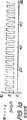
周知の方法は、マスク圧が一定であれば全く正しいものとなる。マスク圧が時間と共に変動する場合(例えば、換気装置を用いた場合)には、上記仮定(i)は無効になるであろう。そして、計算された呼吸エアーフローは、それ故、不正確なものとなるであろう。これは、図1a〜1fに良く示されている。
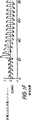
図1aは、バイレベルCPAP治療に用いられたマスク圧であって呼気時における4cmH2Oと吸気時における12cmH2Oとの間で測定され記録されたマスク圧を示している。図1bは、マスク圧と同期する真呼吸エアーフローを示している。時間=21秒であるときに、マスクリークが生じ、この結果、図1cに示す如く処理圧(treatment pressure)と相関関係にあるリークフローが生じている。図1dに示されている測定されたマスクフローは、そのリークフローのため、中心から外れている。次いで、図1eに示す如く、この従来的方法により、多数の呼吸回数に亘ってリークフローが計算され決定される。この結果得られる計算された呼吸フロー、つまり、図1fに示される如く測定された流れから計算されたリークフローを差し引いたものは、正確な平均値になっているが、しかし、このフローのスケールは大きさに関して不正確であり、正と負のエアーフローのピークの表示は誤っている。
他の従来技術は、欧州特許公開第0714670A2号公報に開示されている。この公報は、圧力に依存するリーク成分の計算を含んでいる。その方法は、吸気の開始と、次の吸気の開始との正確な識別に基礎を置いている。換言すれば、リークの計算は、既知の呼吸に対する平均値として出され、後続の呼吸に適用される。
この方法は、以前になされた呼吸のスタート時点と終了時点とが不明である場合には用いることができない。一般に、呼吸のスタート時点を正確に計算することは困難である。このことは、特に、リークに突然の変化が生じる直後になる場合に当てはまる。
さらに、この方法は、呼吸の努力を全く行わない患者であって例えば無呼吸時に瞬間的に全く換気されない患者に対しては効果がないであろう。なぜなら、無呼吸時には、計算を行うための呼吸の始めと終わりとが全くないからである。
本願発明は、圧力関数としてのリーク流量における変動を説明すべく、リークフローと真呼吸エアーフローとの決定を求めるものである。
発明の概要
本発明は、機械換気において、リーク通路を有するマスクにおける瞬間リークフローを測定する方法を開示する。この方法は、
(a)マスクにおける瞬間エアフローを測定するステップと、
(b)マスクにおける瞬間圧力を測定するステップと、
(c)上記リーク通路の非線形コンダクタンスを、ローパスフィルタに通した上記瞬間エアフローをローパスフィルタに通した上記瞬間圧力の平方根で割ったものとして見積もるステップと、
(d)上記コンダクタンスに上記瞬間圧力の平方根を掛けて、それを上記瞬間リークフローとして測定するステップと、を含む。
本発明はさらに、マスクリークの存在下においてマスクによって患者が受け取る呼吸ガスの、瞬間呼吸エアフローを測定する方法を開示する。この方法は、
(a)マスクにおける瞬間エアフローを測定するステップと、
(b)マスクにおける瞬間圧力を測定するステップと、
(c)上記リーク通路の非線形コンダクタンスを、ローパスフィルタに通した上記瞬間エアフローをローパスフィルタに通した上記瞬間圧力の平方根で割ったものとして見積もるステップと、
(d)上記コンダクタンスに上記瞬間圧力の平方根を掛けて、それを瞬間リークフローとして測定するステップと、
(e)瞬間エアフローから瞬間リークフローを引いて、それを呼吸エアフローとして計算するステップと、を含む。
本発明はさらに、マスクリークの存在下においてマスクによって患者が受け取る呼吸ガスの、呼吸エアフローを測定する装置を開示する。この装置は、
マスクまたはその近傍に配置され、マスクの瞬間エアフローおよび圧力を測定するトランスデューサ手段と、処理手段とを含む。
処理手段は、リーク通路の非線形コンダクタンスを、ローパスフィルタに通した上記瞬間エアフローをローパスフィルタに通した上記瞬間圧力の平方根で割ったものとして見積もり;上記コンダクタンスに上記瞬間圧力の平方根を掛けて、それを瞬間リークフローとして測定し;瞬間エアフローから瞬間リークフローを引いて、それを呼吸エアフローとして計算する。
さらに、本発明は、気道に正圧を連続的に供給する処置、または機械換気を行う装置を開示する。この装置は、
供給する呼吸ガスを発生するタービンと、
タービンへの連結部を備えるガス供給チューブと、
上記供給チューブへの連結部を備えており、患者の気道に呼吸ガスを供給するマスクと、
リーク通路の非線形コンダクタンスを、ローパスフィルタに通した上記瞬間エアフローをローパスフィルタに通した上記瞬間圧力の平方根で割ったものとして見積もり;上記コンダクタンスに上記瞬間圧力の平方根を掛けて、それを瞬間リークフローとして測定し;瞬間エアフローから瞬間リークフローを引いて、それを呼吸エアフローとして計算する処理手段と、
フロー発生装置を制御し、計算された呼吸エアフローに基づいて、マスク圧および(または)マスクエアフローを制御する制御手段と、を備える。
さらに本発明は、上述の各ステップを実行するコンピュータプログラムを開示する。
好ましい一形態においては、ローパスフィルタリングの時間定数は、瞬間リークフローの急激な変化に応じて、動的に調整される。
本発明の具体例は、従来技術に比べて有利である。呼吸相の変遷がいつ生じたのかを知る必要はない。患者の呼吸状態を知る必要がないので、重要な結果がもたらされる。すなわち、患者または機械換気装置における無呼吸(すなわち、ノーフロー)の場合におけるリークフローの計算が正確となる。
【図面の簡単な説明】
本発明の具体例を添付の図面を参照して説明する。
図1a〜1fは、従来技術の方法において、呼吸エアフローを計算する基になる圧力およびエアフローをトレースしたものである。
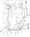
図2aおよびbは、換気支援装置の2つの具体例を示す概略図である。
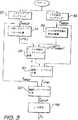
図3は、瞬間呼吸エアフローを測定する方法を示すフローチャートである。
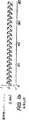
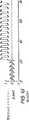
図4は、呼吸エアフローを計算する基になる圧力、エアフロー、その他をトレースしたものである。
図5は、換気支援装置の別の具体例を示す概略図である。
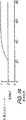
図6は、計算された呼吸エアフローが増加しながらゼロと交差した1つ前の時刻からの時間tZIが予想時間TIよりも長い場合において、程度AIを計算するのに使用するファジーメンバーシップ関数を示している。
図7は、計算された呼吸エアフローfRESPが大きな正の値をとる場合において、程度BIを計算するのに使用するファジーメンバーシップ関数を示している。
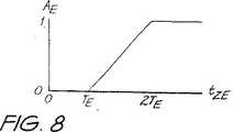
図8は、計算された呼吸エアフローが減少しながらゼロと交差した1つ前の時刻からの時間tZEが予想時間TEよりも長い場合において、程度AEを計算するのに使用するファジーメンバーシップ関数を示している。
図9は、呼吸エアフローfRESPが大きな負の値をとる場合において、程度BEを計算するのに使用するファジーメンバーシップ関数を示している。
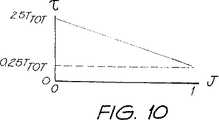
図10は、インデックスJと時間定数τとの関係を示している。
好ましい実施形態の詳細な説明
図2aは、本発明を具体化した機械換気装置10を示す。
患者は、任意の公知タイプのノーズマスク12を装着する。患者は、同様に、フェイスマスク又はナサル(鼻)プロング/ピロウを装着することも可能であり、あるいは、代わりに、適所に気道内チューブを有することも可能である。タービン/ブロワー14は、電気モータ16に機械的に接続されているが、空気すなわち呼吸できるガスをその入口18で受け、呼吸できるガスを吐出圧で吐出チューブ/ホース20に供給する。吐出チューブ/ホース20は、その他端がノーズマスク12との接続部を有する。呼吸を補助するために、このようにして、呼吸できるガスが患者の気道に与えられ、患者が吐き出した呼気は、一般にはマスク12の近くにある吐出チューブ20の出口22から大気へ放出される。
吐出チューブ20には、マスク12と出口22との間に呼吸タコグラフ24が配置され、呼吸タコグラフ24を横断しホース28,30により差圧センサ32にそれぞれ至る2つの圧力信号P2およびP1を与える。マスク12内のガスのフローは、差圧P2−P1により決定され、フロー信号fdとなる。また、マスク圧P2も、呼吸ホース28から取られた拍動ライン36により圧力センサ34に至り、圧力センサ34から吐出圧力信号pm出力を生成する。
フロー信号fdと圧力信号pmとの両方は、連続して信号を処理するために一般には50Hzのレートでサンプリングするマイクロコントローラ34に伝達される。
マイクロコントローラ38は、フローと圧力信号(fd,Pm)を処理して、電子式モータサーボコントローラ42に与えられる出力制御信号yoを生成し、次に、モータ速度制御出力信号voを生成する。この信号はモータ16に与えられタービン14の回転速度を制御し、ノーズマスク12で所望の処置圧P2となるようにする。
モータサーボコントローラ42は、制御信号yoを用いて信号pmの形の実際の吐出圧を補償する、ネガティブフィードバック制御技術を採用する。便利なように、この制御をマイクロコントローラ38のオペレーションとは独立に行うようにしてもよい。
マイクロコントローラ38のオペレーションは、呼吸エアーフローの計算に関する限り、大略、次のようになる。サンプリング法により、マスクリークのコンダクタンスを計算し、次に、瞬間のリークフローを計算する。リークフローは、全マスクフローから引き算され、真の瞬間呼吸エアーフローを計算する。
図2bは、機械換気中に真の呼吸エアーフローを決定するためのシステムの他の実施例を示している。図1bの機械換気システム10'は、図1aのシステムとまず第1に相違するのは、マイクロコンピュータ38はベンチレータ50の制御において何ら役割を果たすことがなく、むしろ、電気的に変換されたマスク圧およびフロー信号pm,fdを受けてデータ処理して瞬間呼吸フローfRESPを決定して生成するに過ぎない点である。ベンチレータ50は、オシレータ44により与えられる内部ドライブ信号を有する。また、モータサーボコントローラは、フィードバック制御の形でマスク圧信号pmを受けても受けなくてもよい。実際、ベンチレータ50は、任意の便利な形の公知の一般的な換気デバイスにより、実現可能である。
コントローラソフトウエアは、コントローラ38内にあり、概要を上述した呼吸エアーフローを決定するとき、図3のフローチャートに示したように、以下のステップを実行する
本明細書中においては、「平均」という用語は、ローパスフィルタリングステップの結果の最も一般的な検出に用い、算術平均に制限するものではない。
1.サンプリング信号fMASKを与えるマスクエアーフローfdと、サンプリング信号PMASKを与えるマスク圧Pmとを、たとえばT=20ミリ秒のインターバルで繰り返してサンプリングする(ステップ50,52)。
2.時定数として10秒を用いてエアーフローfMASKをローパスフィルタリングした結果となるように、平均リークLP(L)を計算する(ステップ54)。
3.時定数として10秒を用いてマスク圧PMASKの平方根をローパスフィルタリングした結果となるように、マスク圧の平方根の平均LP(PMASK1/2)を計算する(ステップ56)。
4.リークのコンダクタンスGを、次に式により計算する(ステップ58)。
G=LP(L)/LP(PMASK1/2)
5.瞬間リークフローfLEAKを、次の式により計算する(ステップ60)
fLEAK=G・PMASK1/2
リークフローがなければ、LP(L)の値はゼロに等しくなり、そのうえGも、したがってfLEAKもそうなる。したがって、リークがゼロに等しい−ノンリークの場合は、方法も変わる。
この際リークフローは、リークフロー検出のために必要とされるのと同様に、決定される。必要ならば、瞬間呼吸エアーフローは、以下のステップによって次に決定されることが可能である。
6.マスクフローから瞬間リークを引くことによって、瞬間呼吸エアーフローを計算する(ステップ62)。
fRESP=fMASK−fLEAK
図4aから図4hは、図2bに関して上述した実施態様の方法を示している。t=21秒のとき、約1リットル/秒の連続するリークが持ち込まれる。図4eは、平均マスクフローを示す。図4fは、計算されたコンダクタンスGを表し、これから、図4gに示したように、マスクリークを見積もることができる。最後に、図4hは、どのようにして約30秒以内で計算された呼吸エアーフローをリカバーするかを示しており、重要なことに、エアーフローの正しくスケール化された真の大きさを与える。
瞬間出力信号yoのセッティングに関して、マイクロコントローラは、大略、以下のステップを実行する。
7.もし計算された真の呼吸エアーフローfRESPがしきい値、例えば0.05リットル/秒を超えれば、yoは吸気圧PINSPに対応する値にセットされる。そうでなければ、yoは呼気圧PEXSPに対応する値にセットされる。一般に、吸気圧PINSPは呼気圧PEXSPより高いが、連続する正の気道圧の場合には、吸気圧PINSPが呼気圧PEXSPと等しくてもよい(ステップ66)。
fMASKからyoを決定する多くの他の方法をステップ7で用いてもよいことが理解できる。たとえば、マーチン・ジェイ・トービンの『機械換気の原理と実際』(マグロー・ヒル・インコーポレイテッド、1994年)のテキスト中に開示されている。
換気を制御するために、患者の換気を測定することが必要である。リークが存在するとき、換気補助装置により与えられた換気は、患者に与えられた換気よりも大きい。バルブ複合システムを用いて吐き出されたエアーストリームを集め、次に吐き出された換気を計算することによって、換気をサーボコントロールするデバイスは、これと対抗する。これは、重く、複雑で、高価であるので、家庭で寝ている間にセッティングして用いるデバイスには不適切である。開示された実施例は、リークの非線形コンダクタンスを連続的に測定し、圧力の関数としてリークした瞬間フローを見込むことによって、リークを補償する。
図5は、本発明を具体的に示した換気支援装置10'の別の配置を示す。この配置において、呼吸タコグラフ24'は、タービン14と吐出ホース20との間に配置されている。
この配置は、マスク12の領域から圧力検出ホースと呼吸タコグラフとを取り除く。マスクでの圧力PMASKは、タービン14での吐出圧力と、エアー吐出ホース20での圧力降下とから計算される。あらゆる特別な吐出ホースに対するPMASKは、呼吸タコグラフ24'でのフローの関数として知られている。さらに、マイクロコントローラ38は、タービン14でのフローからマスクを通るフローから、出口22を通るフローを差し引いて計算しなければならない。
より詳細には、このことは、タービン14における圧力P3を圧力センサ34で測定して電気信号ptを発生させるステップを最初に備えている。次に、差圧p4−p3は、差圧センサ32によって呼吸タコグラフ24'を横切って測定されて、電気信号ftを発生させる。サンプリングされた方法において、ptとftとは、デジタル化されてサンプリングされたタービン圧力PTURBINEとフロー信号FTURBINEとを発生させる。
マスクでの圧力PMASKとマスクでのサンプリングされたエアーフローfMASKとは、タービン圧力PTURBINEとタービンの出口でのフローFTURBINEとから以下のように計算される。
1.エアー吐出チューブ20での圧力降下ΔPTUBEは、タービンの出口でのフローFTURBINEから計算される。
2.マスクでの圧力PMASKは、タービンでの圧力PTURBINEから、エアー吐出チューブ20での圧力降下ΔPTUBEを差し引いて計算される。
PMASK=PTURBINE−ΔPTUBE
3.出口22を通るフローfEXHAUSTは、マスクでの圧力PMASKから計算される。
fEXHAUST=sign(PMASK)×K3(abs(PMASK))0.5
ここで、K3は経験的に決定される。
4.マスク12に入るフローfMASKは、タービン14でのフローから出口22を通るフローを差し引いて計算される。
fMASK=fTURBINE−fEXHAUST
前述の実施形態は、瞬間的なエアーフローと瞬間圧力の平方根との両方を10秒の時定数τでローパスフィルタリングしていることを示している。この時定数τは、都合良く且つ動的に調整可能である。
リークのコンダクタンスが突然変化するならば、計算されたコンダクタンスは、最初不正確であり、徐々に正しい値に近づく。そのときの速度はローパスフィルタの時定数が長いならば遅く、ローパスフィルタの時定数が短いならば早い。逆に、リークのインピーダンスが安定しているならば、時定数が長ければ長いほど、瞬間的なリークの計算はより正確になる。したがって、リークが安定しているならば時定数を長くすることが望ましく、リークが突然変化するならば時定数を短くすることが望ましい。そして、リークがその中間的状態に安定しているならば、時定数を中間的にすることが望ましい。
リークのコンダクタンスが大きく且つ突然に増加するならば、計算された呼吸のエアーフローは不正確になる。特に、明らかな吸息の間に、計算された呼吸のエアーフローは、普通の吸息の予想時間と比べて大きく且つ正の値である。逆に、リークのコンダクタンスが突然減少するならば、明らかな呼気の間に、計算された呼吸のエアーフローは、普通の呼気の予想時間と比べて大きく且つ負の値である。
したがって、リークが突然変化するという確実性のインデックスが以下のように導かれる。すなわち、エアーフローがゼロから離れて或る大きな量まで長くなるほど、インデックスは大きくなる。ローパスフィルタの時定数インデックスと逆に変化するように調整される。操作において、リークが突然に大きく変化するならば、インデックスは大きくなり、リークのコンダクタンスの計算に対する時定数は小さくなり、リークコンダクタンスの新しい値に急速に収束することができる。逆に、リークが長い間安定しているならば、インデックスは小さくなり、リークのコンダクタンスの計算に対する時定数は大きくなり、瞬間的な呼吸のエアーフローを正確に計算することができる。計算された瞬間的な呼吸のエアーフローが長い間長くなる、中間的な状態のスペクトラムにおいて、インデックスは連続的に大きくなり、リークの計算に対する時定数は、連続的に減少する。例えば、リークが実際には一定であり、且つ患者が単に大きなため息をついただけであるか、あるいはリークが突然増加したのかどうかが不明確である瞬間において、インデックスは中間的な値となり、リークのインピーダンスの計算のための時定数も中間的な値となるであろう。ある修正的なアクションが非常に早く起ることが1つの利点である。
別の利点は、欧州特許公開第0714670A2号公報に先行技術として記載されているように、リーク修正アルゴリズムが制御の範囲外であり、再スタートしなければならないという瞬間がないということである。
好ましい実施形態において、上記のインデックスは、ファジー論理を用いて導かれる。エアーフローが予想より長いものに対して正であるファジーの程度A1は、図6に示されるファジーメンバーシップ関数を用いて、計算された呼吸のエアーフロー信号がゼロを横切って正となる時間tZ1と、特別な患者に対する普通の吸気の予想時間TIとから計算される。エアーフローが大きくて正であるファジーの程度B1は、図7に示されるファジーメンバーシップ関数を用いて、瞬間的な呼吸エアーフローから計算される。リークが突然増加する確実性の程度の瞬間的なインデックスIIは、A1及びB1のファジー交点(小さいほう)として計算される。
比較可能な計算が以下のように呼気に対して行なわれる。エアーフローが予想より長いものに対して負であるファジーの程度A1は、図8に示されるファジーメンバーシップ関数を用いて、計算された呼吸のエアーフロー信号がゼロを横切って正となる時間tZEと、特別な患者に対する普通の呼気の予想時間TEとから計算される。エアーフローが大きくて負であるファジーの程度BEは、図9に示されるファジーメンバーシップ関数を用いて、瞬間的な呼吸のエアーフローから計算される。リークが突然減少する確実性の程度の瞬間的なインデックスIEは、AE及びBEのファジー交点として計算される。
リークの突然変化する(増加する又は現象する)程度の瞬間的なインデックスIは、インデックスII及びIEのファジーユニオン(大きいほう)として計算される。瞬間的なインデックスIは、ピーク検出器を通過し、続いて、例えば2秒の時定数でローパスフィルタを通って、所望のインデックスJを与える。インデックスIが直ちに大きくなるならば、インデックスJはまず大きくなって2秒間その状態を維持する。リークのコンダクタンスの計算に用いられた、ローパスフィルタに対する時定数τは、図10に示すように、インデックスJと逆に変化するように調整される。例えば、普通の呼吸サイクルの予想時間が4秒であるならば、インデックスJがゼロ(リークが安定する完全な確実性に対応する)のとき時定数は10秒にセットされ、インデックスJが単一である(リークが突然変化する完全な確実性に対応する)とき時定数は1秒にセットされ、その中間的な場合のとき時定数は中間的な値にセットされている。
しかしながら、実施の形態は、換気支援を準備するための装置について言及しているが、本発明は全ての形の機械換気と、連続的な気道加圧処置を準備するための装置とに適用可能であるということが理解される。装置は、一定の処置圧力、複数レベル(IPAP及びEPAP)処置、自動セッティング(調整)処置、上記注釈文のエム・ヨウネスによって教えられるような釣り合いのとれた支援換気(PVA)を含む他の形の機械換気を準備するためのものである。
上述した方法は、マイクロコントローラーによって、ディスクリート組み合わせロジック要素によって、又はアナログ回路によって実行されるコンピュータープログラムの形で実行される。TECHNICAL FIELD The present invention relates to a method and apparatus for determining airflow leaks and true breathing airflow, particularly when performing mechanical ventilation.
The determination of airflow can be made for patients who take spontaneous or non-spontaneous breaths, or for patients in a state between these breathing states. The present invention is not limited to this, but is particularly suitable for patients who are in a sensory state and are spontaneously breathing and need ventilation assistance over a long period of time, especially during sleep. Is preferred.
Background Art In this specification, the term “mask” should be understood to include all forms of devices for guiding breathable gases into the human respiratory tract. These devices include nasal masks, nasal and mouth masks, nasal cones (prongs) / pillows, airway tubes or airway incision (airway formation) tubes.
When performing mechanical ventilation, breathable gas is supplied through the mask at a higher pressure, for example, during inspiration and lower during exhalation. It is beneficial to measure respiratory airflow when performing mechanical ventilation in order to fully evaluate therapy and control the operation of the ventilator.
The breathing airflow is usually measured with a breathing airflow meter provided in the gas guide path between the mask and the ventilator. Leaks between the mask and the patient are inevitable. This respiratory airflow meter measures the sum of the respiratory airflow and the leak flow rate. If the instantaneous leak flow is known, the respiratory airflow can be calculated by subtracting the leak flow from the respiratory airflow meter flow.
Known methods for correcting the leak flow are as follows: (i) the leak is substantially constant, and (ii) the inspiratory and expiratory breathing airflow will cancel out for a sufficiently long time. , Based on the assumption. If these assumptions are met, the average flow rate flowing through the breathing airflow meter over a sufficiently long period will be equal to the magnitude of the leak, and true breathing airflow will be May be able to calculate.
The known method is completely correct if the mask pressure is constant. If the mask pressure varies with time (eg, when using a ventilator), the assumption (i) would be invalid. And the calculated respiratory airflow will therefore be inaccurate. This is well illustrated in Figures 1a-1f.
FIG. 1a shows the mask pressure used for bi-level CPAP treatment, measured and recorded between 4 cmH2 O during expiration and 12 cmH2 O during inspiration. FIG. 1b shows true breathing airflow synchronized with the mask pressure. A mask leak occurs when time = 21 seconds, resulting in a leak flow that is correlated with the treatment pressure as shown in FIG. 1c. The measured mask flow shown in FIG. 1d is off-center due to its leak flow. Then, as shown in FIG. 1e, according to this conventional method, the leak flow is calculated and determined over a large number of breaths. The resulting calculated respiratory flow, i.e. the flow measured as shown in Figure 1f minus the calculated leak flow, is an accurate average, but the scale of this flow Is inaccurate with respect to size and the indication of positive and negative airflow peaks is incorrect.
Another prior art is disclosed in European Patent Publication No. 0714670A2. This publication includes a calculation of the pressure dependent leak component. The method is based on an accurate discrimination between the start of inspiration and the start of the next inspiration. In other words, the leak calculation is averaged over known breaths and applied to subsequent breaths.
This method cannot be used when the start time and end time of breathing previously performed are unknown. In general, it is difficult to accurately calculate the start time of breathing. This is especially true when there is a sudden change in the leak.
Furthermore, this method would not be effective for patients who do not make any respiratory effort and are not ventilated instantaneously during apnea, for example. This is because during apnea, there is no beginning and end of breathing for calculation.
The present invention seeks to determine the leak flow and true breathing air flow to account for variations in leak flow as a function of pressure.
SUMMARY OF THE INVENTION The present invention discloses a method for measuring instantaneous leak flow in a mask having a leak passage in mechanical ventilation. This method
(A) measuring the instantaneous airflow in the mask;
(B) measuring the instantaneous pressure at the mask;
(C) estimating the non-linear conductance of the leak path as the instantaneous airflow passed through the low pass filter divided by the square root of the instantaneous pressure passed through the low pass filter;
(D) multiplying the conductance by the square root of the instantaneous pressure and measuring it as the instantaneous leak flow.
The present invention further discloses a method for measuring the instantaneous respiratory airflow of respiratory gas received by a patient by a mask in the presence of a mask leak. This method
(A) measuring the instantaneous airflow in the mask;
(B) measuring the instantaneous pressure at the mask;
(C) estimating the non-linear conductance of the leak path as the instantaneous airflow passed through the low pass filter divided by the square root of the instantaneous pressure passed through the low pass filter;
(D) multiplying the conductance by the square root of the instantaneous pressure and measuring it as an instantaneous leak flow;
(E) subtracting the instantaneous leak flow from the instantaneous air flow and calculating it as a respiratory air flow.
The present invention further discloses an apparatus for measuring respiratory airflow of respiratory gas received by a patient by a mask in the presence of a mask leak. This device
Transducer means disposed at or near the mask and measuring instantaneous airflow and pressure of the mask, and processing means.
The processing means estimates the non-linear conductance of the leak path as the instantaneous air flow passed through the low-pass filter divided by the square root of the instantaneous pressure passed through the low-pass filter; Is measured as the instantaneous leak flow; subtract the instantaneous leak flow from the instantaneous air flow and calculate it as the respiratory air flow.
In addition, the present invention discloses a device that provides a continuous supply of positive pressure to the airway, or mechanical ventilation. This device
A turbine for generating breathing gas to be supplied;
A gas supply tube with a connection to the turbine;
A mask for supplying respiratory gas to the patient's respiratory tract, comprising a connection to the supply tube;
Estimate the non-linear conductance of the leak path as the instantaneous air flow passed through the low pass filter divided by the square root of the instantaneous pressure passed through the low pass filter; Processing means for subtracting instantaneous leak flow from instantaneous air flow and calculating it as respiratory air flow;
Control means for controlling the flow generator and for controlling the mask pressure and / or the mask airflow based on the calculated respiratory airflow.
Furthermore, this invention discloses the computer program which performs each above-mentioned step.
In a preferred form, the low-pass filtering time constant is dynamically adjusted in response to a sudden change in instantaneous leak flow.
Embodiments of the present invention are advantageous over the prior art. There is no need to know when the change in respiratory phase occurred. Significant results are brought about because it is not necessary to know the patient's respiratory status. That is, the leak flow calculation in the case of apnea (ie, no flow) in the patient or mechanical ventilator is accurate.
[Brief description of the drawings]
Specific examples of the present invention will be described with reference to the accompanying drawings.
FIGS. 1 a-1 f are traces of pressure and air flow from which prior art methods calculate respiratory airflow.
2a and 2b are schematic diagrams showing two specific examples of a ventilation support device.
FIG. 3 is a flowchart illustrating a method for measuring instantaneous respiratory airflow.
FIG. 4 is a trace of pressure, airflow, etc., from which breathing airflow is calculated.
FIG. 5 is a schematic view showing another specific example of the ventilation support apparatus.
FIG. 6 shows the fuzzy member used to calculate the degree AI when the time tZI from the previous time when the calculated respiratory airflow increased and crossed zero was longer than the expected time TI. The ship function is shown.
7, when the calculated respiratory airflow fRESP takes a large positive value shows a fuzzy membership function used to calculate the extent BI.
FIG. 8 shows the fuzzy member used to calculate the degree AE when the time tZE from the previous time when the calculated respiratory airflow decreased but crossed zero was longer than the expected time TE The ship function is shown.
FIG. 9 shows the fuzzy membership function used to calculate the degreeBE when the respiratory airflow fRESP takes a large negative value.
FIG. 10 shows the relationship between the index J and the time constant τ.
Detailed Description of the Preferred Embodiment FIG. 2a shows a
The patient wears any known type of
The
Both the flow signal fd and the pressure signal pm are communicated to the
The
The operation of the
FIG. 2b shows another embodiment of a system for determining true respiratory airflow during mechanical ventilation. The mechanical ventilation system 10 'of FIG. 1b differs from the system of FIG. 1a primarily in that the
The controller software resides in the
1. the mask airflow fd to provide a sampling signal fMASK, and the mask pressure Pm to give a sampling signal PMASK, repeatedly sampled at intervals of, for example, T = 20 msec (
2. Calculate the average leak LP (L) so as to obtain the result of low-pass filtering the airflow fMASK using 10 seconds as the time constant (step 54).
3. The average LP (PMASK1/2 ) of the square root of the mask pressure is calculated so as to obtain the result of low-pass filtering the square root of the mask pressure PMASK using 10 seconds as a time constant (step 56).
4. The leak conductance G is then calculated from the equation (step 58).
G = LP (L) / LP (PMASK1/2 )
5. Calculate the instantaneous leak flow fLEAK using the following formula (step 60).
fLEAK = G ・ PMASK1/2
Without leak flow, the value of LP (L) is equal to zero, and so is G, and therefore fLEAK . Therefore, if the leak is equal to zero-non-leak, the method also changes.
At this time, the leak flow is determined in the same manner as needed for leak flow detection. If necessary, the instantaneous breathing airflow can then be determined by the following steps.
6. Calculate the instantaneous breathing airflow by subtracting the instantaneous leak from the mask flow (step 62).
fRESP = fMASK − fLEAK
Figures 4a to 4h illustrate the method of the embodiment described above with respect to Figure 2b. When t = 21 seconds, a continuous leak of about 1 liter / second is introduced. FIG. 4e shows the average mask flow. FIG. 4f represents the calculated conductance G from which the mask leak can be estimated as shown in FIG. 4g. Finally, Figure 4h shows how to recover the calculated respiratory airflow within about 30 seconds, and importantly gives the true scaled true magnitude of the airflow .
Respect setting of the instantaneous output signal yo, microcontroller, generally, perform the following steps.
7. If the calculated true respiratory airflow fRESP threshold, for example if it exceeds 0.05 liters / sec, yo is set to a value corresponding to the intake air pressure PINSP. Otherwise, yo is set to a value corresponding to the breath pressure PEXSP. In general, the inspiratory pressure PINSP is higher than the expiratory pressure PEXSP , but in the case of continuous positive airway pressure, the inspiratory pressure PINSP may be equal to the expiratory pressure PEXSP (step 66).
Many other methods of determining yo from fMASK can be seen that may be used in Step 7. For example, it is disclosed in the text of Martin Jay Tobin's “The Principles and Practices of Mechanical Ventilation” (Maglow Hill Incorporated, 1994).
In order to control ventilation, it is necessary to measure patient ventilation. When there is a leak, the ventilation provided by the ventilatory assist device is greater than the ventilation provided to the patient. This is countered by devices that servo the ventilation by collecting the exhaled air stream using the valve complex system and then calculating the exhaled ventilation. This is heavy, complex and expensive and is unsuitable for devices that are set and used while sleeping at home. The disclosed embodiment compensates for leaks by continuously measuring the non-linear conductance of the leak and allowing for the instantaneous flow that leaked as a function of pressure.
FIG. 5 shows another arrangement of the
This arrangement removes the pressure sensing hose and breathing tachograph from the area of the
More particularly, this comprises the steps of generating an electrical signal pt pressure P3 in the
The pressure PMASK at the mask and the sampled airflow fMASK at the mask are calculated from the turbine pressure PTURBINE and the flow FTURBINE at the turbine outlet as follows:
1. The pressure drop ΔPTUBE in the
2. The pressure PMASK at the mask is calculated by subtracting the pressure drop ΔPTUBE at the
PMASK = PTURBINE −ΔPTUBE
3. The flow fEXHAUST through the
fEXHAUST = sign (PMASK ) x K3 (abs (PMASK ))0.5
Here, K3 is determined empirically.
4. The flow fMASK entering the
fMASK = fTURBINE −fEXHAUST
The previous embodiment shows that both the instantaneous airflow and the square root of the instantaneous pressure are low-pass filtered with a time constant τ of 10 seconds. This time constant τ can be adjusted conveniently and dynamically.
If the conductance of the leak changes suddenly, the calculated conductance is initially inaccurate and gradually approaches the correct value. The speed at that time is slow if the time constant of the low-pass filter is long, and fast if the time constant of the low-pass filter is short. Conversely, if the leak impedance is stable, the longer the time constant, the more accurate the instantaneous leak calculation. Therefore, it is desirable to increase the time constant if the leak is stable, and it is desirable to shorten the time constant if the leak changes suddenly. If the leak is stable in its intermediate state, it is desirable to set the time constant to intermediate.
If the leak conductance is large and increases suddenly, the calculated respiratory airflow will be inaccurate. In particular, during apparent inspiration, the calculated respiratory airflow is large and positive compared to the expected time of normal inspiration. Conversely, if the leak conductance suddenly decreases, the calculated respiratory airflow during a clear exhalation is large and negative compared to the expected time of normal exhalation.
Therefore, an index of certainty that the leak changes suddenly is derived as follows. That is, the index increases as the airflow increases from zero to a certain large amount. It is adjusted so as to change in reverse to the time constant index of the low pass filter. In operation, if the leak suddenly changes greatly, the index will increase, the time constant for the leak conductance calculation will be small, and it can converge rapidly to the new value of the leak conductance. Conversely, if the leak is stable for a long time, the index will be small and the time constant for calculating the conductance of the leak will be large and the instantaneous respiratory airflow can be accurately calculated. In an intermediate spectrum where the calculated instantaneous breathing airflow is long, the index increases continuously and the time constant for the leak calculation decreases continuously. For example, at a moment when the leak is actually constant and the patient is just sighing or it is unclear whether the leak has suddenly increased, the index becomes an intermediate value, The time constant for calculating the impedance will also be an intermediate value. One advantage is that certain corrective actions occur very quickly.
Another advantage is that, as described as prior art in EP 0714670A2, there is no moment when the leak correction algorithm is out of control and must be restarted.
In a preferred embodiment, the above index is derived using fuzzy logic. The degree of fuzzy A1 for which the airflow is positive for longer than expected is the time during which the calculated respiration airflow signal is positive across zero using the fuzzy membership function shown in FIG. Calculated from tZ1 and the expected time TI of normal inspiration for a particular patient. The degree of fuzzy B1 where the airflow is large and positive is calculated from the instantaneous respiratory airflow using the fuzzy membership function shown in FIG. The instantaneous index II of the degree of certainty that the leak will suddenly increase is calculated as the fuzzy intersection (smaller) of A1 and B1 .
A comparable calculation is performed on exhalation as follows. The degree of fuzzy A1 that is negative for longer airflow than expected is the time during which the calculated respiration airflow signal is positive across zero using the fuzzy membership function shown in FIG. Calculated from tZE and the expected time TE of normal exhalation for a particular patient. The degree of fuzzyBE with large and negative airflow is calculated from the instantaneous breathing airflow using the fuzzy membership function shown in FIG. The instantaneous index IE of the degree of certainty that the leak will suddenly decrease is calculated as the fuzzy intersection of AE and BE.
The instantaneous index I of the degree of sudden change (increase or phenomenon) of the leak is calculated as the fuzzy union (larger) of the indices II and IE. The instantaneous index I is passed through the peak detector, followed by a low-pass filter, for example with a time constant of 2 seconds, giving the desired index J. If index I grows immediately, index J first grows and remains in that state for 2 seconds. The time constant τ for the low-pass filter used for calculating the conductance of the leak is adjusted so as to change opposite to the index J, as shown in FIG. For example, if the expected time of a normal breathing cycle is 4 seconds, the time constant is set to 10 seconds when index J is zero (corresponding to full certainty that the leak is stable), and index J is single (Corresponding to the full certainty that the leak suddenly changes) the time constant is set to 1 second, and in the intermediate case the time constant is set to an intermediate value.
However, although the embodiments refer to a device for preparing ventilation assistance, the present invention is applicable to all forms of mechanical ventilation and devices for preparing continuous airway pressurization procedures. It is understood that. The device is available in other forms, including constant treatment pressure, multi-level (IPAP and EPAP) treatment, automatic setting treatment, and balanced support ventilation (PVA) as taught by M Yonesse in the above note. To prepare for mechanical ventilation.
The method described above is performed in the form of a computer program executed by a microcontroller, by discrete combinational logic elements, or by analog circuitry.
Claims (29)
Translated fromJapanese瞬間のマスクのエアーフローおよび圧力を決定するために、マスクに、もしくはマスクの近傍に配置されたトランスジューサー手段と、そして、
上記マスクの上記エアーフローをローパスフィルタリングすることで平均リークを算出し、かつ上記トランスジューサー手段から得られる上記マスク圧力から該マスク圧力の平方根を求めてローパスフィルタリングすることで平均マスク圧平方根を算出し、かつ上記平均リーク及び上記平均マスク圧平方根を元に上記リークの非線形コンダクタンスを算出し該コンダクタンスから瞬間リークフローを算出し、そして上記トランスジューサー手段から得られる上記マスクの瞬間エアーフローと上記瞬間リークフローとから瞬間呼吸エアーフローを計算するプロセッサー手段と、
を備えた呼吸エアーフロー決定装置。A device that determines the respiratory airflow of a patient receiving breathable gas at a mask in the presence of a mask leak,
Transducer means located at or near the mask to determine the instantaneous mask airflow and pressure; and
Calculating an average leakage bythe low-passfilter the said air flow of themask,andthe mean mask pressure squarebylow-pass filteringfrom the resulting the mask pressurethe square root ofthe maskpressurefromthe ToransujiYusa meanscalculated, and the average leak及beauty the mean mask pressure squarecalculating theleakageflowmoments from calculating thenonlinearconductance of the leak based ontheconductance,andair moment ofthe transducer means orwe obtained the maskandprocessors meansfor calculating the instantaneous respiratory airflow from aflow and the instantaneous reKufuro,
Respiratory airflow determination device.
上記コンダクタンスが突然に変化する程度のインデックスを得ることによって、反対の意味における上記時定数を、上記インデックスにおける相当の変化に変えることによって、時定数を動的に調整する請求項2記載の装置。The processor means is
3. The apparatus of claim 2, wherein the time constant is dynamically adjusted by changing the time constant in the opposite sense to a substantial change in the index by obtaining an index to which the conductance suddenly changes.
計算されたエアーフローの絶対大きさが、予期されるよりも長いがために予期されるよりも大きくなるまでの程度を決定することにより、上記インデックスを上記計算された呼吸エアーフローから得る請求項3記載の装置。The processor means is
The index is obtained from the calculated respiratory airflow by determining the extent to which the absolute magnitude of the calculated airflow is longer than expected and therefore greater than expected. 3. The apparatus according to 3.
呼吸可能なガスの供給を発生するためのタービンと、
上記タービンに接続されたガス吐出チューブと、
患者の気道に上記呼吸可能なガスを供給すべく上記吐出チューブに連結されたマスクと、
瞬間のマスクのエアーフローおよび圧力を決定するために、マスクに、もしくはマスクの近傍に配置されたトランスジューサー手段と、
上記マスクの上記エアーフローをローパスフィルタリングすることで平均リークを算出し、かつ上記トランスジューサー手段から得られる上記マスク圧力から該マスク圧力の平方根を求めてローパスフィルタリングすることで平均マスク圧平方根を算出し、かつ上記平均リーク及び上記平均マスク圧平方根を元にリーク通路の非線形コンダクタンスを算出し該コンダクタンスから瞬間リークフローを算出し、そして上記トランスジューサー手段から得られる上記マスクの瞬間エアーフローと上記瞬間リークフローとから瞬間呼吸エアーフローを計算するプロセッサー手段と、
計算された上記瞬間呼吸エアーフローに基づいてマスク圧及び/又はマスクエアーフローを制御するため上記タービンを制御する制御手段とを備えた装置。A device that provides continuous positive airway pressure treatment or mechanical ventilation,
A turbine for generating a supply of breathable gas;
A gas discharge tube connected to the turbine;
A mask coupled to the discharge tube to supply the breathable gas to a patient's respiratory tract;
Transducer means located at or near the mask to determine the instantaneous mask airflow and pressure;
Calculating an average leakage bythe low-passfilter the said air flow of themask,andthe mean mask pressure squarebylow-pass filteringfrom the resulting the mask pressurethe square root ofthe maskpressurefromthe ToransujiYusa meanscalculated, and the average leak及beauty the mean mask pressure squarecalculating theleakageflowmoments from calculating thenonlinearconductance of the leak passage based ontheconductance,andair moment ofthe transducer means orwe obtained the maskandprocessors meansfor calculating the instantaneous respiratory airflow from aflow and the instantaneous reKufuro,
And control meansfor controllingthe turbinesto control themaskpressure and / or the mask airflowbased on the calculated the instantaneous respiratory airflow.
上記コンダクタンスが突然に変化する程度のインデックスを得ることによって時定数を動的に調整し、且つ反対の意味における上記時定数を、上記インデックスにおける相当の変化に変える請求項9記載の装置。The processor means is
10. The apparatus of claim 9, wherein the time constant is dynamically adjusted by obtaining an index to which the conductance suddenly changes, and the time constant in the opposite sense is changed to a substantial change in the index.
計算されたエアーフローの絶対大きさが、予期されるよりも長いがために予期されるよりも大きくなるまでの程度を決定することにより、上記インデックスを上記計算された呼吸エアーフローから得る請求項10記載の装置。The processor means is
The index is obtained from the calculated respiratory airflow by determining the extent to which the absolute magnitude of the calculated airflow is longer than expected and therefore greater than expected. 10. The device according to 10.
(a)マスクにおける瞬間エアーフローを決定する計算ステップと、
(b)マスクにおける瞬間圧力を決定する計算ステップと、
(c)上記マスクの上記瞬間エアーフローをローパスフィルタリングすることで平均リークを算出し、かつ上記マスクの上記瞬間圧力から該マスク圧力の平方根を求めてローパスフィルタリングすることで平均マスク圧平方根を算出し、かつ上記平均リーク及び上記平均マスク圧平方根を元にリークの非線形コンダクタンスを計算するステップと、
(d)上記非線形コンダクタンスと上記マスクの瞬間圧力の平方根とを乗算して瞬間リークフローを計算する計算ステップと、そして、
(e)瞬間エアーフローから瞬間リークフローを引いて、呼吸エアーフローを計算する計算ステップとを含むコンピュータープログラム。A computer program that determines the instantaneous respiratory airflow of a patient receiving breathable gas at a mask in the presence of a mask leak, the program receiving input data of instantaneous airflow and instantaneous pressure at the mask,
(A) a calculation step for determining the instantaneous airflow in the mask;
(B) a calculation step for determining the instantaneous pressure in the mask;
(C)the instantaneous air flow of the maskto calculate the average leakage byRopasufuIrutaringu, andcalculates anaverage mask applanation lateralrootsby low pass filteringthe square root of the mask pressure from the momentary pressure inthemaskAndcalculating a non-linear conductance of the leak based on themean leak and the mean mask pressuresquare root;
(D) calculating the instantaneous leak flow by multiplying the nonlinear conductance by the square root of the instantaneous pressure of the mask; and
(E) a computer program comprising calculating steps for subtracting instantaneous leak flow from instantaneous air flow to calculate respiratory air flow.
マスク内の圧力及びマスクを通ったエアーフローの瞬間値を決定するために、マスクに、もしくはマスクの近傍に配置されたトランスジューサー手段と、
普通の吸息より長い時間間隔にわたって決定された、マスク圧の平方根の平均及びマスクの平均リークに基づいてリークコンダクタンスを算出し、前記算出されたリークコンダクタンス及び決定された瞬間のマスク圧力の関数として瞬間リークフローを算出するプロセッサー手段とを備えた装置。A device for determining instantaneous leak flow from a patient's mask during mechanical ventilation,
Transducer means located at or near the mask to determine the pressure in the mask and the instantaneous value of air flow through the mask;
Was determined over a longer time interval than usual inspiration, to calculate the leakage conductancebased on the average leak average and the mask ofmask pressure square root function of the calculated leak conductance and mask pressure at the moment determined And a processor means for calculating the instantaneous leak flow.
圧縮された呼吸可能なガスを供給するフロー発生装置と、
前記フロー発生装置と接続を持ったガスデリバリーシステムと、
前記ガスデリバリーシステムと接続を持ち、前記ガスを患者の気道に前記ガスを供給するマスクと、
前記マスク内の圧力を連続的に測定しマスクを通るエアーフローが決定されるトランスジューサー手段と、
普通の吸息よりも長い時間間隔にわたって決定された、マスク圧の平方根の平均及びマスクの平均リークに基づいてマスクリークコンダクタンスを算出し、算出されたリークコンダクタンスと決定されたマスク圧力の値の関数として瞬間リークフローを算出するプロセッサー手段と、
前記マスクエアーフローと算出されたリークフローに基づいて少なくとも1つのマスク圧力及びマスクエアーフローを制御するために前記フロー発生装置を調整する制御手段と、を備えた装置。A device for mechanical ventilation of a patient,
A flow generator for supplying compressed breathable gas;
A gas delivery system connected to the flow generator;
A mask having a connection to the gas delivery system and supplying the gas to a patient's respiratory tract;
Transducer means for continuously measuring the pressure in the mask and determining the air flow through the mask;
Was determined over a longer time interval than usualinspiration, calculates a mask leakconductancebasedon the average leak average and the mask of the square root of the mask pressure, the value of the mask pressure determined as the calculated leak conductance Processor means for calculating the instantaneous leak flow as a function;
And a control means for adjusting the flow generator to control at least one mask pressure and mask airflow based on the mask airflow and the calculated leak flow.
マスク内の圧力とマスクを通るエアーフローの瞬間値を決定するための手段と、
通常の吸息よりも長い時間に渡って計測された圧力とエアーフローの瞬間値のそれぞれの平均値の関数として、リークコンダクタンスを算出する手段と、
算出されたリークコンダクタンスと決定された瞬間のマスク内の圧力の関数として瞬間リークフローを算出する手段と、を備えた装置。An apparatus for determining instantaneous leak flow from a patient's mask,
Means for determining the pressure in the mask and the instantaneous value of airflow through the mask;
Means for calculating leakage conductance as a function of the respective average values of pressure and instantaneous airflow values measured over a longer period of time than normal inspiration;
Means for calculating an instantaneous leak flow as a function of the calculated leak conductance and the pressure in the determined instantaneous mask.
マスク内の圧力及びマスクを通るエアーフローの瞬間値を決定する手段と、
圧力とエアーフローの瞬間値のそれぞれの平均値の関数として、リークコンダクタンスを算出する手段と、
算出されたリークコンダクタンスと決定された瞬間のマスク内の圧力の値の関数として、瞬間リークフローを算出する手段と、を備え、
リークコンダクタンスを決定するために圧力とエアーフローの値が用いられる前記時間間隔は、前記算出されたリークコンダクタンスの変化の割合とは逆に変化する装置。An apparatus for determining instantaneous leak flow from a patient's mask,
Means for determining the pressure in the mask and the instantaneous value of air flow through the mask;
Means for calculating the leak conductance as a function of the average value of each of the instantaneous values of pressure and air flow;
Means for calculating instantaneous leakage flow as a function of the calculated leakage conductance and the value of the pressure in the determined instantaneous mask;
An apparatus in which the time interval in which pressure and airflow values are used to determine leak conductance varies inversely with the calculated rate of change in leak conductance.
前記患者の気道へマスクを通して圧縮された呼吸可能なガスを供給するための手段と、
マスク内の圧力を連続的に測定し、マスクを通るエアーフローを決定する手段と、
普通の吸息より長い時間間隔にわたって決定された、マスク圧の平方根の平均及びマスクの平均リークに基づいてマスクリークコンダクタンスを算出し、算出されたリークコンダクタンスと決定されたマスク圧力との関数として、瞬間リークフローを算出する手段と、
マスクエアーフローと算出されたリークフローにしたがって呼吸可能なガスの供給を調整する手段とを備えた装置。A device for supplying breathable gas to a patient,
Means for supplying compressed breathable gas through a mask to the patient's airway;
Means for continuously measuring the pressure in the mask and determining the air flow through the mask;
Was determined over a longer time interval than usualinspiration, as a function of the mask leak conductance calculates mask pressure determined and calculated leak conductancebased on the average leak average and the mask ofmask pressure square root Means for calculating the instantaneous leak flow;
An apparatus comprising a mask air flow and means for adjusting a supply of breathable gas according to the calculated leak flow.
Applications Claiming Priority (3)
| Application Number | Priority Date | Filing Date | Title |
|---|---|---|---|
| AU1638 | 1985-07-25 | ||
| AUPO1638AAUPO163896A0 (en) | 1996-08-14 | 1996-08-14 | Determination of respiratory airflow |
| PCT/AU1997/000517WO1998006449A1 (en) | 1996-08-14 | 1997-08-14 | Determination of leak and respiratory airflow |
Publications (2)
| Publication Number | Publication Date |
|---|---|
| JP2000516491A JP2000516491A (en) | 2000-12-12 |
| JP3635097B2true JP3635097B2 (en) | 2005-03-30 |
Family
ID=3795951
Family Applications (1)
| Application Number | Title | Priority Date | Filing Date |
|---|---|---|---|
| JP50923998AExpired - Fee RelatedJP3635097B2 (en) | 1996-08-14 | 1997-08-14 | Leak and respiratory airflow determination |
Country Status (8)
| Country | Link |
|---|---|
| US (7) | US6152129A (en) |
| EP (1) | EP0929336B1 (en) |
| JP (1) | JP3635097B2 (en) |
| AT (1) | ATE342083T1 (en) |
| AU (2) | AUPO163896A0 (en) |
| CA (1) | CA2263126C (en) |
| DE (1) | DE69736808T2 (en) |
| WO (1) | WO1998006449A1 (en) |
Families Citing this family (158)
| Publication number | Priority date | Publication date | Assignee | Title |
|---|---|---|---|---|
| US5632269A (en)* | 1989-09-22 | 1997-05-27 | Respironics Inc. | Breathing gas delivery method and apparatus |
| EP1149603A3 (en) | 1991-12-20 | 2003-10-22 | Resmed Limited | Ventilator for continuous positive airway pressure breathing (CPAP) |
| US6000396A (en)* | 1995-08-17 | 1999-12-14 | University Of Florida | Hybrid microprocessor controlled ventilator unit |
| AU2002306200B2 (en)* | 1996-08-14 | 2004-12-23 | Resmed Limited | Determination of Leak and Respiratory Airflow |
| AUPO163896A0 (en)* | 1996-08-14 | 1996-09-05 | Resmed Limited | Determination of respiratory airflow |
| AUPO247496A0 (en)* | 1996-09-23 | 1996-10-17 | Resmed Limited | Assisted ventilation to match patient respiratory need |
| AUPO301796A0 (en) | 1996-10-16 | 1996-11-07 | Resmed Limited | A vent valve apparatus |
| US5881717A (en)* | 1997-03-14 | 1999-03-16 | Nellcor Puritan Bennett Incorporated | System and method for adjustable disconnection sensitivity for disconnection and occlusion detection in a patient ventilator |
| SE9704643D0 (en)* | 1997-12-12 | 1997-12-12 | Astra Ab | Inhalation apparatus and method |
| AUPP693398A0 (en)* | 1998-11-05 | 1998-12-03 | Resmed Limited | Fault diagnosis in CPAP and NIPPV devices |
| AUPP783198A0 (en) | 1998-12-21 | 1999-01-21 | Resmed Limited | Determination of mask fitting pressure and correct mask fit |
| US6467477B1 (en)* | 1999-03-26 | 2002-10-22 | Respironics, Inc. | Breath-based control of a therapeutic treatment |
| US6910480B1 (en)* | 1999-09-15 | 2005-06-28 | Resmed Ltd. | Patient-ventilator synchronization using dual phase sensors |
| AU778469B2 (en)* | 1999-09-15 | 2004-12-09 | Resmed Limited | Patient-ventilator synchronization using dual phase sensors |
| US6758216B1 (en)* | 1999-09-15 | 2004-07-06 | Resmed Limited | Ventilatory assistance using an external effort sensor |
| US6553992B1 (en) | 2000-03-03 | 2003-04-29 | Resmed Ltd. | Adjustment of ventilator pressure-time profile to balance comfort and effectiveness |
| US6532956B2 (en)* | 2000-03-30 | 2003-03-18 | Respironics, Inc. | Parameter variation for proportional assist ventilation or proportional positive airway pressure support devices |
| DE10021581B4 (en)* | 2000-04-27 | 2005-01-13 | Auergesellschaft Gmbh | Volume control for fan filter units |
| NZ524990A (en) | 2000-09-28 | 2005-02-25 | Invacare Corp | Carbon dioxide-based BI-level CPAP control |
| US6546930B1 (en) | 2000-09-29 | 2003-04-15 | Mallinckrodt Inc. | Bi-level flow generator with manual standard leak adjustment |
| US6644310B1 (en)* | 2000-09-29 | 2003-11-11 | Mallinckrodt Inc. | Apparatus and method for providing a breathing gas employing a bi-level flow generator with an AC synchronous motor |
| AU2036902A (en)* | 2000-12-11 | 2002-06-24 | Resmed Ltd | Methods and apparatus for stroke patient treatment |
| ATE468874T1 (en)* | 2000-12-29 | 2010-06-15 | Resmed Ltd | CHARACTERIZATION OF MASK SYSTEMS |
| AUPR315401A0 (en) | 2001-02-16 | 2001-03-15 | Resmed Limited | An apparatus for supplying clean breathable gas |
| DE10161057A1 (en)* | 2001-12-12 | 2003-07-10 | Heptec Gmbh | Process for controlling the differential pressure in a CPAP device and CPAP device |
| DE10200183A1 (en)* | 2002-01-04 | 2003-07-17 | Heptec Gmbh | Method for determining the mask pressure of a CPAP (continuous positive airway pressure) breathing device to enable its pressure regulation, whereby a theoretical pressure is determined to which a correction pressure is applied |
| US7448383B2 (en)* | 2002-03-08 | 2008-11-11 | Kaerys, S.A. | Air assistance apparatus providing fast rise and fall of pressure within one patient's breath |
| US7438073B2 (en)* | 2002-03-08 | 2008-10-21 | Kaerys S.A. | Air assistance apparatus for computing the airflow provided by only means of pressure sensors |
| US7000611B2 (en) | 2002-03-26 | 2006-02-21 | Klemperer Walter G | Mouthpiece, nasal seal, head appliance, apparatus, and methods of treating sleep apnea |
| CA2386639A1 (en)* | 2002-05-16 | 2003-11-16 | Dynamic Mt Gmbh | Portable electronic spirometer |
| US7475685B2 (en)* | 2003-03-24 | 2009-01-13 | Weinmann Geräte fär Medizin GmbH & Co. KG | Method and device for detecting leaks in respiratory gas supply systems |
| EP1477199A1 (en)* | 2003-05-15 | 2004-11-17 | Azienda Ospedaliera Pisana | Apparatus for non-invasive mechanical ventilation |
| US7621270B2 (en) | 2003-06-23 | 2009-11-24 | Invacare Corp. | System and method for providing a breathing gas |
| US7152598B2 (en) | 2003-06-23 | 2006-12-26 | Invacare Corporation | System and method for providing a breathing gas |
| US7435236B2 (en) | 2003-06-27 | 2008-10-14 | Navilyst Medical, Inc. | Pressure actuated valve with improved biasing member |
| US7114497B2 (en)* | 2003-07-18 | 2006-10-03 | Acoba, Llc | Method and system of individually controlling airway pressure of a patient's nares |
| US7607437B2 (en) | 2003-08-04 | 2009-10-27 | Cardinal Health 203, Inc. | Compressor control system and method for a portable ventilator |
| US8118024B2 (en) | 2003-08-04 | 2012-02-21 | Carefusion 203, Inc. | Mechanical ventilation system utilizing bias valve |
| ES2592262T3 (en)* | 2003-08-04 | 2016-11-29 | Carefusion 203, Inc. | Portable respirator system |
| US7527053B2 (en) | 2003-08-04 | 2009-05-05 | Cardinal Health 203, Inc. | Method and apparatus for attenuating compressor noise |
| US8156937B2 (en) | 2003-08-04 | 2012-04-17 | Carefusion 203, Inc. | Portable ventilator system |
| US7252652B2 (en) | 2003-08-29 | 2007-08-07 | Boston Scientific Scimed, Inc. | Valved catheters including high flow rate catheters |
| US6837243B1 (en)* | 2003-09-30 | 2005-01-04 | Scott Technologies, Inc. | Automatic transfer regulator for hose-line respirator |
| US20070135724A1 (en) | 2003-10-17 | 2007-06-14 | Ujhazy Anthony J | Methods and apparatus for heart failure treatment |
| US8584676B2 (en)* | 2003-11-19 | 2013-11-19 | Immediate Response Technologies | Breath responsive filter blower respirator system |
| EP2394687B1 (en)* | 2003-11-26 | 2020-07-22 | ResMed Pty Ltd | Apparatus for the systemic control of ventilatory support in the presence of respiratory insufficiency |
| CN1901959B (en)* | 2003-12-29 | 2010-05-12 | 雷斯梅德有限公司 | Mechanical ventilation in sleep-disordered breathing |
| US9314608B2 (en) | 2004-01-29 | 2016-04-19 | Angiodynamics, Inc | Pressure activated safety valve with high flow slit |
| US7878198B2 (en) | 2004-03-31 | 2011-02-01 | Michael Farrell | Methods and apparatus for monitoring the cardiovascular condition of patients with sleep disordered breathing |
| US20060005834A1 (en)* | 2004-07-07 | 2006-01-12 | Acoba, Llc | Method and system of providing therapeutic gas to a patient to prevent breathing airway collapse |
| JP4975621B2 (en) | 2004-08-10 | 2012-07-11 | レスメド・リミテッド | Method and apparatus for humidification with a profiled supply of gas suitable for breathing |
| DE102004040659A1 (en)* | 2004-08-20 | 2006-02-23 | Weinmann Geräte für Medizin GmbH + Co. KG | Apparatus for ventilation and method for controlling a ventilator |
| US7717110B2 (en)* | 2004-10-01 | 2010-05-18 | Ric Investments, Llc | Method and apparatus for treating Cheyne-Stokes respiration |
| CN101043913B (en) | 2004-10-20 | 2012-02-08 | 雷斯梅德有限公司 | Method and apparatus for detecting futile inspiratory effort and improving patient-ventilator interaction |
| US7984712B2 (en)* | 2004-10-25 | 2011-07-26 | Bird Products Corporation | Patient circuit disconnect system for a ventilator and method of detecting patient circuit disconnect |
| US20060096596A1 (en)* | 2004-11-05 | 2006-05-11 | Occhialini James M | Wearable system for positive airway pressure therapy |
| US20060174885A1 (en)* | 2005-02-08 | 2006-08-10 | Acoba, Llc | Method and related system to control applied pressure in CPAP systems |
| EP1893267B1 (en)* | 2005-06-14 | 2016-09-28 | ResMed Limited | Apparatus for controlling mask leak in cpap treatment |
| ES2585642T3 (en)* | 2005-06-21 | 2016-10-07 | Breas Medical Ab | Device, method and software to compensate for fan leaks |
| CN101291702B (en)* | 2005-10-21 | 2013-05-01 | 雷斯梅德有限公司 | Method and apparatus for improving flow and pressure estimation in CPAP systems |
| US8172766B1 (en) | 2005-11-04 | 2012-05-08 | Cleveland Medical Devices Inc. | Integrated sleep diagnosis and treatment device and method |
| US7942824B1 (en) | 2005-11-04 | 2011-05-17 | Cleveland Medical Devices Inc. | Integrated sleep diagnostic and therapeutic system and method |
| US20070113847A1 (en)* | 2005-11-22 | 2007-05-24 | General Electric Company | Respiratory monitoring with cannula receiving first respiratory airflows and second respiratory airflows |
| US20080078393A1 (en)* | 2005-11-22 | 2008-04-03 | General Electric Company | Respiratory monitoring with cannula receiving respiratory airflows, differential pressure transducer, and ventilator |
| US20070113848A1 (en)* | 2005-11-22 | 2007-05-24 | General Electric Company | Respiratory monitoring with cannula receiving respiratory airflows and exhaled gases |
| US20070113856A1 (en)* | 2005-11-22 | 2007-05-24 | General Electric Company | Respiratory monitoring with cannula receiving respiratory airflows |
| US7422015B2 (en)* | 2005-11-22 | 2008-09-09 | The General Electric Company | Arrangement and method for detecting spontaneous respiratory effort of a patient |
| US20070113850A1 (en)* | 2005-11-22 | 2007-05-24 | General Electric Company | Respiratory monitoring with cannula receiving respiratory airflows and differential pressure transducer |
| JP2009519058A (en)* | 2005-12-16 | 2009-05-14 | ハミルトン・メディカル・アーゲー | Ventilator tube system |
| DE102005061439B3 (en)* | 2005-12-22 | 2007-05-16 | Draeger Medical Ag | Determination of leakage in respiration apparatus uses pressure sensor to measure initial inspiration pressure, pressure being altered during subsequent inspirations and leakage volume calculated |
| US7694677B2 (en)* | 2006-01-26 | 2010-04-13 | Nellcor Puritan Bennett Llc | Noise suppression for an assisted breathing device |
| US7509957B2 (en)* | 2006-02-21 | 2009-03-31 | Viasys Manufacturing, Inc. | Hardware configuration for pressure driver |
| US7747319B2 (en)* | 2006-03-17 | 2010-06-29 | Zoll Medical Corporation | Automated resuscitation device with ventilation sensing and prompting |
| US7762006B2 (en)* | 2006-06-14 | 2010-07-27 | Siestamed, Technologies | Medical equipment drying device |
| EP2789359A3 (en)* | 2006-08-30 | 2014-12-24 | ResMed Ltd. | Determination of leak during CPAP treatment |
| WO2008028247A1 (en)* | 2006-09-07 | 2008-03-13 | Resmed Ltd | Mask and flow generator system |
| UY30892A1 (en)* | 2007-02-07 | 2008-09-02 | Smithkline Beckman Corp | AKT ACTIVITY INHIBITORS |
| EP2144674A4 (en)* | 2007-04-13 | 2012-12-26 | Invacare Corp | Apparatus and method for providing positive airway pressure |
| DE102007033860A1 (en)* | 2007-07-20 | 2009-01-22 | Boehringer Ingelheim Pharma Gmbh & Co. Kg | Test arrangement for testing sealing between mouthpiece of inhaler and user's lips has channel for secondary air around user's lips with second flow measurement device |
| WO2009026562A1 (en)* | 2007-08-22 | 2009-02-26 | The Research Foundation Of The State University Of New York | Breathing-gas delivery and sharing system and method |
| CA2696773A1 (en) | 2007-08-23 | 2009-02-26 | Invacare Corporation | Method and apparatus for adjusting desired pressure in positive airway pressure devices |
| US20090078255A1 (en)* | 2007-09-21 | 2009-03-26 | Bowman Bruce R | Methods for pressure regulation in positive pressure respiratory therapy |
| US20090078258A1 (en)* | 2007-09-21 | 2009-03-26 | Bowman Bruce R | Pressure regulation methods for positive pressure respiratory therapy |
| US7975691B2 (en)* | 2007-10-23 | 2011-07-12 | Eun Jong Cha | Continuous positive airway pressure device by controlling the pressure in the face mask |
| US7800360B2 (en)* | 2007-10-31 | 2010-09-21 | Sony Ericsson Mobile Communications Ab | Connector system with magnetic audio volume control and method |
| US7997885B2 (en) | 2007-12-03 | 2011-08-16 | Carefusion 303, Inc. | Roots-type blower reduced acoustic signature method and apparatus |
| WO2009073650A1 (en) | 2007-12-07 | 2009-06-11 | Mallinckrodt Inc. | Push to install syringe mount for powered injector systems |
| US8272380B2 (en)* | 2008-03-31 | 2012-09-25 | Nellcor Puritan Bennett, Llc | Leak-compensated pressure triggering in medical ventilators |
| US8267085B2 (en) | 2009-03-20 | 2012-09-18 | Nellcor Puritan Bennett Llc | Leak-compensated proportional assist ventilation |
| US10207069B2 (en) | 2008-03-31 | 2019-02-19 | Covidien Lp | System and method for determining ventilator leakage during stable periods within a breath |
| US8746248B2 (en) | 2008-03-31 | 2014-06-10 | Covidien Lp | Determination of patient circuit disconnect in leak-compensated ventilatory support |
| US8888711B2 (en) | 2008-04-08 | 2014-11-18 | Carefusion 203, Inc. | Flow sensor |
| US8257321B2 (en) | 2008-05-21 | 2012-09-04 | Navilyst Medical, Inc. | Pressure activated valve for high flow rate and pressure venous access applications |
| GB2460629B (en)* | 2008-05-28 | 2011-03-30 | Plant Test Services Ltd | Leak detector |
| WO2009149357A1 (en) | 2008-06-06 | 2009-12-10 | Nellcor Puritan Bennett Llc | Systems and methods for ventilation in proportion to patient effort |
| US20100071696A1 (en)* | 2008-09-25 | 2010-03-25 | Nellcor Puritan Bennett Llc | Model-predictive online identification of patient respiratory effort dynamics in medical ventilators |
| EP2168623B1 (en)* | 2008-09-26 | 2011-09-21 | General Electric Company | Arrangement for detecting a leak in anesthesia system |
| US8083721B2 (en) | 2009-01-29 | 2011-12-27 | Navilyst Medical, Inc. | Power injection valve |
| FR2941625B1 (en)* | 2009-02-05 | 2012-05-18 | Materiels Ind Securite | COMBINATION FOR PROTECTING A PERSON AND CORRESPONDING ASSEMBLY |
| US8424521B2 (en) | 2009-02-27 | 2013-04-23 | Covidien Lp | Leak-compensated respiratory mechanics estimation in medical ventilators |
| US8418691B2 (en) | 2009-03-20 | 2013-04-16 | Covidien Lp | Leak-compensated pressure regulated volume control ventilation |
| US8007468B2 (en) | 2009-07-13 | 2011-08-30 | Navilyst Medical, Inc. | Method to secure an elastic component in a valve |
| NZ702309A (en) | 2009-07-16 | 2016-06-24 | Resmed Ltd | Detection of sleep condition |
| US8419597B2 (en) | 2009-08-17 | 2013-04-16 | Emily L. Cooper | Systems and methods for a hill training apparatus for a bicycle trainer |
| GB2474917B (en)* | 2009-11-02 | 2015-12-23 | Scott Health & Safety Ltd | Improvements to powered air breathing apparatus |
| AU2010327420C1 (en) | 2009-12-01 | 2025-10-02 | Fisher & Paykel Healthcare Limited | Breathing assistance apparatus |
| CN101806652B (en)* | 2010-02-02 | 2011-11-09 | 清华大学 | System and method for detecting pipe breakage of steam generator of high temperature gas-cooled reactor |
| US8707952B2 (en) | 2010-02-10 | 2014-04-29 | Covidien Lp | Leak determination in a breathing assistance system |
| EP2368593A1 (en)* | 2010-03-26 | 2011-09-28 | Dräger Medical GmbH | Estimating a leakage flow |
| EP2590702B1 (en)* | 2010-07-09 | 2014-05-14 | Koninklijke Philips N.V. | Leak estimation using leak model identification |
| WO2012014106A1 (en)* | 2010-07-27 | 2012-02-02 | Koninklijke Philips Electronics N.V. | Leak estimation using function estimation. |
| NZ703966A (en) | 2010-07-30 | 2016-07-29 | Resmed Ltd | Methods and devices with leak detection |
| JP5944396B2 (en)* | 2010-10-26 | 2016-07-05 | コーニンクレッカ フィリップス エヌ ヴェKoninklijke Philips N.V. | Pressure line purge system for mechanical ventilators |
| US10561339B2 (en)* | 2010-12-21 | 2020-02-18 | Koninklijke Philips N.V. | System and method for determining carbon dioxide excreted during non-invasive ventilation |
| CN102641536A (en)* | 2011-02-17 | 2012-08-22 | 新利虹科技股份有限公司 | Positive pressure breathing device and air leakage quantity obtaining method thereof |
| US8783250B2 (en) | 2011-02-27 | 2014-07-22 | Covidien Lp | Methods and systems for transitory ventilation support |
| RU2013147615A (en)* | 2011-03-25 | 2015-04-27 | ИНСЛИП ТЕКНОЛОДЖИЗ, ЭлЭлСи | BREATHE-HELPING MACHINE |
| US8714154B2 (en) | 2011-03-30 | 2014-05-06 | Covidien Lp | Systems and methods for automatic adjustment of ventilator settings |
| US8776792B2 (en) | 2011-04-29 | 2014-07-15 | Covidien Lp | Methods and systems for volume-targeted minimum pressure-control ventilation |
| CN103974735A (en) | 2011-09-13 | 2014-08-06 | 雷斯梅德有限公司 | Vent arrangement for respiratory mask |
| JP6225110B2 (en)* | 2011-09-13 | 2017-11-01 | コーニンクレッカ フィリップス エヌ ヴェKoninklijke Philips N.V. | Leak inspection module based on gas pressure |
| US9498589B2 (en) | 2011-12-31 | 2016-11-22 | Covidien Lp | Methods and systems for adaptive base flow and leak compensation |
| US9327089B2 (en)* | 2012-03-30 | 2016-05-03 | Covidien Lp | Methods and systems for compensation of tubing related loss effects |
| US10362967B2 (en) | 2012-07-09 | 2019-07-30 | Covidien Lp | Systems and methods for missed breath detection and indication |
| US9895524B2 (en) | 2012-07-13 | 2018-02-20 | Angiodynamics, Inc. | Fluid bypass device for valved catheters |
| US10076619B2 (en) | 2012-09-11 | 2018-09-18 | Resmed Limited | Vent arrangement for respiratory mask |
| EP2914321B1 (en)* | 2012-10-31 | 2019-02-27 | Maquet Critical Care AB | A breathing apparatus and a method therein |
| US10328222B2 (en) | 2013-03-14 | 2019-06-25 | ResMed Pty Ltd | Vent device for use with a respiratory device |
| NZ728203A (en) | 2013-03-14 | 2018-07-27 | Resmed Ltd | Vent arrangement for a respiratory device |
| US10342942B2 (en) | 2013-03-15 | 2019-07-09 | Fisher & Paykel Healthcare Limited | Respiratory assistance device and method of controlling said device |
| GB201306067D0 (en)* | 2013-04-04 | 2013-05-22 | Smiths Medical Int Ltd | Resuscitator arrangements and flow monitoring |
| US10493223B2 (en)* | 2013-06-19 | 2019-12-03 | Koninklijke Philips N.V. | Determining of subject zero flow using cluster analysis |
| USD737953S1 (en) | 2013-07-26 | 2015-09-01 | Resmed Limited | Patient interface |
| US20160184538A1 (en)* | 2013-08-12 | 2016-06-30 | Koninklijke Philips N.V. | Detecting the fit of a patient interface device |
| US9675771B2 (en) | 2013-10-18 | 2017-06-13 | Covidien Lp | Methods and systems for leak estimation |
| US20150320961A1 (en)* | 2014-05-07 | 2015-11-12 | Oridion Medical 1987 Ltd. | Airway access device |
| US9808591B2 (en) | 2014-08-15 | 2017-11-07 | Covidien Lp | Methods and systems for breath delivery synchronization |
| EP3209357B1 (en) | 2014-10-24 | 2019-07-31 | Koninklijke Philips N.V. | System for controlling leak |
| US9950129B2 (en) | 2014-10-27 | 2018-04-24 | Covidien Lp | Ventilation triggering using change-point detection |
| JP7188884B2 (en) | 2014-12-04 | 2022-12-13 | レスメド・プロプライエタリー・リミテッド | Wearable device for air delivery |
| EP4321198A3 (en)* | 2015-03-20 | 2024-03-27 | ResMed Pty Ltd | Methods and apparatus for ventilatory treatment of respiratory disorders |
| US11027081B2 (en) | 2015-07-07 | 2021-06-08 | Koninklijke Philips N.V. | Method and systems for patient airway and leak flow estimation for non-invasive ventilation |
| EP3334485B1 (en)* | 2015-08-14 | 2024-03-06 | ResMed Pty Ltd | Monitoring respiratory pressure therapy |
| US11266801B2 (en) | 2015-10-09 | 2022-03-08 | University Of Utah Research Foundation | Ventilation devices and systems and methods of using same |
| US10271788B2 (en)* | 2016-02-26 | 2019-04-30 | MGC Diagnostics Corp. | Apparatus and method for measuring energy expenditure using indirect calorimetry |
| US10610678B2 (en) | 2016-08-11 | 2020-04-07 | Angiodynamics, Inc. | Bi-directional, pressure-actuated medical valve with improved fluid flow control and method of using such |
| US11389608B2 (en) | 2016-09-19 | 2022-07-19 | Koninklijke Philips N.V. | Methods and systems for patient airway and leak flow estimation for non-invasive ventilation |
| US12239785B2 (en) | 2016-10-07 | 2025-03-04 | University Of Utah Research Foundation | Ventilation devices and systems and methods of using same |
| WO2019143856A2 (en) | 2018-01-17 | 2019-07-25 | Zoll Medical Corporation | Systems and methods for assisting patient airway management |
| WO2019222258A1 (en) | 2018-05-14 | 2019-11-21 | Covidien Lp | Systems and methods for respiratory effort detection utilizing signal distortion |
| US11752287B2 (en) | 2018-10-03 | 2023-09-12 | Covidien Lp | Systems and methods for automatic cycling or cycling detection |
| US11906097B2 (en)* | 2019-09-04 | 2024-02-20 | Vyaire Medical, Inc. | Ventilation leak component |
| JP2022547229A (en)* | 2019-09-09 | 2022-11-10 | フィッシャー アンド ペイケル ヘルスケア リミテッド | respiratory therapy systems and devices |
| CN112870515B (en)* | 2019-11-29 | 2023-01-31 | 深圳市大雅医疗技术有限公司 | Mask type parameter adjusting method, breathing assistance device and storage medium |
| CN112999478A (en)* | 2019-12-20 | 2021-06-22 | 广州和普乐健康科技有限公司 | Adaptive tidal volume calculation method and device and breathing machine |
| CN110975090A (en)* | 2019-12-20 | 2020-04-10 | 广州和普乐健康科技有限公司 | Breathing machine air leakage calculation method and device, storage medium and computer equipment |
| EP4378506A3 (en)* | 2020-03-06 | 2024-08-07 | ResMed Sensor Technologies Limited | Systems and methods for detecting an intentional leak characteristic curve for a respiratory therapy system |
| CN116850402B (en)* | 2023-08-11 | 2025-09-26 | 常州安康医疗器械有限公司 | Ventilator tube detachment detection method, detachment detection system and related equipment |
Family Cites Families (246)
| Publication number | Priority date | Publication date | Assignee | Title |
|---|---|---|---|---|
| DE459104C (en) | 1928-04-26 | Hans Jancke | Device for preventing snoring | |
| US35295A (en)* | 1862-05-20 | Improvement in water-elevators | ||
| US35339A (en)* | 1862-05-20 | Improvement in tips for fishing-rods | ||
| US2904033A (en)* | 1957-03-04 | 1959-09-15 | Sylvan M Shane | Breathing indicator |
| US3099985A (en)* | 1960-12-21 | 1963-08-06 | Porter C Wilson | Resuscitator |
| SE331590B (en) | 1967-04-04 | 1971-01-04 | Elema Schoenander Ab | |
| US3559638A (en)* | 1967-09-19 | 1971-02-02 | James A Potter | Respiration meter having several modes of operation |
| US3611801A (en)* | 1968-10-28 | 1971-10-12 | Nasa | Respiration monitor |
| US3595228A (en)* | 1968-11-27 | 1971-07-27 | Robert C Simon | Flow line break alarm device |
| US3802417A (en)* | 1968-12-21 | 1974-04-09 | V Lang | Device for combined monitoring and stimulation of respiration |
| US3989037A (en)* | 1970-06-23 | 1976-11-02 | Siemens Aktiengesellschaft | Flow measuring device |
| US3741208A (en)* | 1971-02-23 | 1973-06-26 | B Jonsson | Lung ventilator |
| US3726270A (en) | 1971-09-20 | 1973-04-10 | Syst Res Labor Inc | Pulmonary information transmission system |
| BE791878A (en)* | 1971-11-26 | 1973-03-16 | Bryan Donkin Co Ltd | CHECK VALVE IMPROVEMENT |
| US3914994A (en)* | 1971-12-15 | 1975-10-28 | Philip M Banner | Liquid flow indicating and flow control means |
| CH549392A (en) | 1972-03-27 | 1974-05-31 | Hoffmann La Roche | VENTILATION DEVICE WITH AUTOMATIC REGULATION OF PRESSURE AND FLOW OF BREATHING GAS. |
| US3817246A (en)* | 1972-12-11 | 1974-06-18 | Puritan Bennett Corp | Flow responsive respiration apparatus |
| NO144779C (en) | 1973-05-10 | 1981-11-04 | Adam Klenk | BACKLIGHT AND LUBRICANTS FOR LIQUIDS. |
| CH568756A5 (en)* | 1973-09-07 | 1975-11-14 | Hoffmann La Roche | |
| US3882847A (en)* | 1973-12-11 | 1975-05-13 | Harvey Barry Jacobs | Low-Cost Pneumatic Apnea or Respiration Monitor |
| US3903875A (en)* | 1974-01-24 | 1975-09-09 | Sandoz Ag | Automatically calibrated respiratory ventilation monitor |
| US3903881A (en)* | 1974-04-12 | 1975-09-09 | Bourns Inc | Respirator system and method |
| US3932054A (en)* | 1974-07-17 | 1976-01-13 | Western Engineering & Mfg. Co. | Variable pitch axial fan |
| US3992598A (en)* | 1974-12-04 | 1976-11-16 | Afton Incorporated | Airflow velocity switch |
| US3985467A (en)* | 1975-05-27 | 1976-10-12 | Milton Roy Company | Constant pressure pump |
| DE2537765B2 (en) | 1975-08-25 | 1981-04-09 | Siemens AG, 1000 Berlin und 8000 München | Medical inhalation device for the treatment of diseases of the respiratory tract |
| US4006634A (en)* | 1975-09-17 | 1977-02-08 | National Semiconductor Corporation | Flow meter |
| US3995661A (en)* | 1975-09-22 | 1976-12-07 | Wheelabrator-Frye, Inc. | Flow control valve for magnetic particulate |
| GB1576118A (en) | 1976-06-02 | 1980-10-01 | Boc Ltd | Lung ventilators |
| US4083245A (en)* | 1977-03-21 | 1978-04-11 | Research Development Corporation | Variable orifice gas flow sensing head |
| US4109749A (en)* | 1976-11-09 | 1978-08-29 | Minnesota Mining And Manufacturing Company | Muffler |
| GB1583273A (en) | 1977-05-06 | 1981-01-21 | Medishield Corp Ltd | Lung ventilators |
| US4387722A (en)* | 1978-11-24 | 1983-06-14 | Kearns Kenneth L | Respiration monitor and x-ray triggering apparatus |
| US4249527A (en)* | 1979-02-09 | 1981-02-10 | Case Western Reserve University | Continuous positive airway pressure administrating apparatus |
| US4320766A (en)* | 1979-03-13 | 1982-03-23 | Instrumentarium Oy | Apparatus in medicine for the monitoring and or recording of the body movements of a person on a bed, for instance of a patient |
| US4433693A (en)* | 1979-09-27 | 1984-02-28 | Hochstein Peter A | Method and assembly for monitoring respiration and detecting apnea |
| US4301833A (en)* | 1979-10-05 | 1981-11-24 | Donald Iii Robert A | Flow responsive safety valve |
| DE3021326A1 (en) | 1980-06-06 | 1981-12-17 | Drägerwerk AG, 2400 Lübeck | DEVICE FOR MEASURING AT LEAST TWO PNEUMATIC LUNG PARAMETERS AND MEASURING METHODS THEREFOR |
| DE3023648A1 (en)* | 1980-06-24 | 1982-01-21 | Jaeger, Erich, 8700 Würzburg | DEVICE FOR EXAMINING THE RESPIRATORY RESPIRATORY SENSITIVITY |
| US4322594A (en)* | 1980-06-27 | 1982-03-30 | Respiratory Care, Inc. | Temperature control system with alarm and shut down for non-tracking condition of dual thermometers |
| US4312235A (en)* | 1980-09-02 | 1982-01-26 | United Technologies Corporation | Sensor and meter for measuring the mass flow of a fluid stream |
| US4414982A (en)* | 1980-11-26 | 1983-11-15 | Tritec Industries, Inc. | Apneic event detector and method |
| US4449525A (en)* | 1981-02-08 | 1984-05-22 | White Daniel S | Pulmonary resuscitator |
| US4396034A (en)* | 1981-02-23 | 1983-08-02 | Cherniak George S | Arcuate swing check valve |
| US4381788A (en)* | 1981-02-27 | 1983-05-03 | Douglas David W | Method and apparatus for detecting apnea |
| DE3276924D1 (en)* | 1981-04-24 | 1987-09-17 | Somed Pty Ltd | Device for treating snoring sickness |
| US4481944A (en) | 1981-11-19 | 1984-11-13 | Bunnell Life Systems, Inc. | Apparatus and method for assisting respiration |
| US4580575A (en)* | 1982-06-14 | 1986-04-08 | Aequitron Medical, Inc. | Apnea monitoring system |
| US4448058A (en)* | 1982-07-02 | 1984-05-15 | Sensormedics Corporation | Respiratory gas analysis instrument having improved volume calibration method and apparatus |
| US4550726A (en)* | 1982-07-15 | 1985-11-05 | Mcewen James A | Method and apparatus for detection of breathing gas interruptions |
| US4602644A (en)* | 1982-08-18 | 1986-07-29 | Plasmedics, Inc. | Physiological detector and monitor |
| EP0104004A1 (en)* | 1982-09-06 | 1984-03-28 | Graham Cameron Grant | Fluid flowmeter and method of measuring flow rate |
| US4506666A (en)* | 1982-12-03 | 1985-03-26 | Kircaldie, Randall And Mcnab | Method and apparatus for rectifying obstructive apnea |
| US4530334A (en)* | 1982-12-09 | 1985-07-23 | Solex (U.K.) Limited | Air flow metering |
| JPS59107399A (en) | 1982-12-13 | 1984-06-21 | リオン株式会社 | How to measure the degree of nasalization |
| US4499914A (en)* | 1983-04-14 | 1985-02-19 | Litton Systems, Inc. | Selector valve for an aircraft on board oxygen generation system with high pressure oxygen backup |
| US4576179A (en)* | 1983-05-06 | 1986-03-18 | Manus Eugene A | Respiration and heart rate monitoring apparatus |
| US4738266A (en)* | 1983-05-09 | 1988-04-19 | Thatcher John B | Apnoea monitor |
| JPS6015134A (en) | 1983-07-07 | 1985-01-25 | Unitika Ltd | Manufacture of piezo-electric and pyroelectric film |
| US4655213A (en) | 1983-10-06 | 1987-04-07 | New York University | Method and apparatus for the treatment of obstructive sleep apnea |
| US4579114A (en)* | 1983-10-11 | 1986-04-01 | Wisdom Corporation | Mouth to mouth resuscitation device |
| US4860766A (en)* | 1983-11-18 | 1989-08-29 | Respitrace Corp. | Noninvasive method for measuring and monitoring intrapleural pressure in newborns |
| IL71468A (en)* | 1984-04-08 | 1988-06-30 | Dan Atlas | Apnea monitoring method and apparatus |
| GB2166871A (en) | 1984-09-03 | 1986-05-14 | Vickers Plc | Respiration monitor |
| FI76929C (en) | 1984-09-25 | 1989-01-10 | Etelae Haemeen Keuhkovammayhdi | Inhalation dosing device intended for accurate dosing of disposable drugs given for respiratory illness in the examination stage and / or drugs given as a spray during treatment. |
| NZ209900A (en)* | 1984-10-16 | 1989-08-29 | Univ Auckland | Automatic inhaler |
| EP0346566A3 (en) | 1984-12-27 | 1990-05-02 | Teijin Limited | Oxygen enriching apparatus |
| US4595016A (en)* | 1985-01-30 | 1986-06-17 | Mine Safety Appliances Co. | APNEA monitor |
| US4971065A (en)* | 1985-02-11 | 1990-11-20 | Pearce Stephen D | Transducer for detecting apnea |
| US4686999A (en)* | 1985-04-10 | 1987-08-18 | Tri Fund Research Corporation | Multi-channel ventilation monitor and method |
| US4648396A (en)* | 1985-05-03 | 1987-03-10 | Brigham And Women's Hospital | Respiration detector |
| FI81500C (en)* | 1985-05-23 | 1990-11-12 | Etelae Haemeen Keuhkovammayhdi | Respiratory Treatment Unit |
| US4648407A (en)* | 1985-07-08 | 1987-03-10 | Respitrace Corporation | Method for detecting and differentiating central and obstructive apneas in newborns |
| US4587967A (en) | 1985-07-09 | 1986-05-13 | Lifecare Services, Inc. | Oxygen enriched reciprocating piston respirator |
| IT1185906B (en)* | 1985-09-13 | 1987-11-18 | Luciano Gattinoni | BIOMEDICAL SYSTEM AND APPARATUS FOR MEASURING WITH PRECISION OF THE PRESSURE AND VOLUME CHANGE VALUES IN THE PATIENT'S LUNGS |
| US4870960A (en)* | 1985-10-07 | 1989-10-03 | Litton Systems, Inc. | Backup breathing gas supply for an oxygen concentrator system |
| JPS6294175A (en)* | 1985-10-18 | 1987-04-30 | 鳥取大学長 | Respiration synchronous type gas blowing apparatus and method |
| US4671297A (en)* | 1985-10-25 | 1987-06-09 | Schulze Jr Karl F | Method and apparatus for monitoring infants on assisted ventilation |
| US4747403A (en) | 1986-01-27 | 1988-05-31 | Advanced Pulmonary Technologies, Inc. | Multi-frequency jet ventilation technique and apparatus |
| US5052400A (en)* | 1986-02-20 | 1991-10-01 | Dietz Henry G | Method and apparatus for using an inhalation sensor for monitoring and for inhalation therapy |
| US4773411A (en)* | 1986-05-08 | 1988-09-27 | Downs John B | Method and apparatus for ventilatory therapy |
| US4825802A (en)* | 1986-07-24 | 1989-05-02 | Societe Anonyme Drager | Pheumatic alarm for respirator |
| US4674492A (en) | 1986-07-25 | 1987-06-23 | Filcon Corporation | Alarm system for respirator apparatus and method of use |
| US4803471A (en)* | 1986-10-24 | 1989-02-07 | Hudson Oxygen Therapy Sales Co. | Ventilator monitor and alarm apparatus |
| DE3636669C2 (en)* | 1986-10-28 | 2001-08-16 | Siemens Ag | Arrangement for delivering aerosol to a patient's airways and / or lungs |
| US5024219A (en)* | 1987-01-12 | 1991-06-18 | Dietz Henry G | Apparatus for inhalation therapy using triggered dose oxygenator employing an optoelectronic inhalation sensor |
| GB8704104D0 (en) | 1987-02-21 | 1987-03-25 | Manitoba University Of | Respiratory system load apparatus |
| FR2611505B1 (en)* | 1987-03-05 | 1997-01-10 | Air Liquide | METHOD AND DEVICE FOR SUPPLYING RESPIRATORY OXYGEN |
| GB8712223D0 (en) | 1987-05-23 | 1987-07-01 | Care R J | Electronic auto flow control |
| US4777963A (en)* | 1987-06-18 | 1988-10-18 | Mckenna Kevin | Respiration monitor |
| US5522382A (en) | 1987-06-26 | 1996-06-04 | Rescare Limited | Device and method for treating obstructed breathing having a delay/ramp feature |
| US5199424A (en) | 1987-06-26 | 1993-04-06 | Sullivan Colin E | Device for monitoring breathing during sleep and control of CPAP treatment that is patient controlled |
| US5322057A (en) | 1987-07-08 | 1994-06-21 | Vortran Medical Technology, Inc. | Intermittent signal actuated nebulizer synchronized to operate in the exhalation phase, and its method of use |
| US5388571A (en) | 1987-07-17 | 1995-02-14 | Roberts; Josephine A. | Positive-pressure ventilator system with controlled access for nebulizer component servicing |
| US4795314A (en)* | 1987-08-24 | 1989-01-03 | Cobe Laboratories, Inc. | Condition responsive pump control utilizing integrated, commanded, and sensed flowrate signals |
| US4802485A (en)* | 1987-09-02 | 1989-02-07 | Sentel Technologies, Inc. | Sleep apnea monitor |
| US4938212A (en)* | 1987-10-16 | 1990-07-03 | Puritan-Bennett Corporation | Inspiration oxygen saver |
| US4838258A (en)* | 1987-10-26 | 1989-06-13 | Gibeck-Dryden Corporation | Gas sampling lumen for breathing system |
| FR2624744B1 (en) | 1987-12-18 | 1993-09-17 | Inst Nat Sante Rech Med | METHOD FOR REGULATING AN ARTIFICIAL VENTILATION DEVICE AND SUCH A DEVICE |
| US5065756A (en)* | 1987-12-22 | 1991-11-19 | New York University | Method and apparatus for the treatment of obstructive sleep apnea |
| US4915103A (en)* | 1987-12-23 | 1990-04-10 | N. Visveshwara, M.D., Inc. | Ventilation synchronizer |
| FI82808C (en)* | 1987-12-31 | 1991-04-25 | Etelae Haemeen Keuhkovammayhdi | Ultraljudfinfördelningsanordning |
| US4856506A (en)* | 1988-01-11 | 1989-08-15 | Jinotti Walter J | Apparatus for mouth-to-mouth resuscitation |
| US5170798A (en)* | 1988-02-10 | 1992-12-15 | Sherwood Medical Company | Pulmonary function tester |
| US4887607A (en) | 1988-03-16 | 1989-12-19 | Beatty Robert F | Apparatus for and method of spectral analysis enhancement of polygraph examinations |
| US5335656A (en) | 1988-04-15 | 1994-08-09 | Salter Laboratories | Method and apparatus for inhalation of treating gas and sampling of exhaled gas for quantitative analysis |
| US4823788A (en)* | 1988-04-18 | 1989-04-25 | Smith Richard F M | Demand oxygen controller and respiratory monitor |
| GB8809715D0 (en) | 1988-04-25 | 1988-06-02 | Pa Consulting Services | Fluid mass flow & density sensor |
| US4870963A (en)* | 1988-05-06 | 1989-10-03 | Carol Bussell | Respiratory aid device |
| US4957107A (en)* | 1988-05-10 | 1990-09-18 | Sipin Anatole J | Gas delivery means |
| DE3817985A1 (en) | 1988-05-27 | 1989-12-07 | Salvia Werk Gmbh | DEVICE FOR SUPPORTING THE SPONTANEOUS BREATHING OF A PATIENT |
| US4972842A (en)* | 1988-06-09 | 1990-11-27 | Vital Signals, Inc. | Method and apparatus for precision monitoring of infants on assisted ventilation |
| US5048515A (en) | 1988-11-15 | 1991-09-17 | Sanso David W | Respiratory gas supply apparatus and method |
| US4982738A (en)* | 1988-11-30 | 1991-01-08 | Dr. Madaus Gmbh | Diagnostic apnea monitor system |
| US5090248A (en)* | 1989-01-23 | 1992-02-25 | The University Of Melbourne | Electronic transducer |
| US5105354A (en)* | 1989-01-23 | 1992-04-14 | Nippon Kayaku Kabushiki Kaisha | Method and apparatus for correlating respiration and heartbeat variability |
| US4989599A (en)* | 1989-01-26 | 1991-02-05 | Puritan-Bennett Corporation | Dual lumen cannula |
| US4913401A (en)* | 1989-01-26 | 1990-04-03 | Respironics, Inc. | Valve apparatus |
| US4938210A (en)* | 1989-04-25 | 1990-07-03 | Trudell Medical | Inhalation chamber in ventilator circuit |
| US4960118A (en)* | 1989-05-01 | 1990-10-02 | Pennock Bernard E | Method and apparatus for measuring respiratory flow |
| US5259373A (en) | 1989-05-19 | 1993-11-09 | Puritan-Bennett Corporation | Inspiratory airway pressure system controlled by the detection and analysis of patient airway sounds |
| US5134995A (en) | 1989-05-19 | 1992-08-04 | Puritan-Bennett Corporation | Inspiratory airway pressure system with admittance determining apparatus and method |
| US5845636A (en) | 1989-05-19 | 1998-12-08 | Puritan Bennett Corporation | Method and apparatus for maintaining patient airway patency |
| US5107831A (en) | 1989-06-19 | 1992-04-28 | Bear Medical Systems, Inc. | Ventilator control system using sensed inspiratory flow rate |
| US5239995A (en)* | 1989-09-22 | 1993-08-31 | Respironics, Inc. | Sleep apnea treatment apparatus |
| USRE35295E (en) | 1989-09-22 | 1996-07-16 | Respironics, Inc. | Sleep apnea treatment apparatus |
| US5148802B1 (en) | 1989-09-22 | 1997-08-12 | Respironics Inc | Method and apparatus for maintaining airway patency to treat sleep apnea and other disorders |
| US5632269A (en) | 1989-09-22 | 1997-05-27 | Respironics Inc. | Breathing gas delivery method and apparatus |
| US5009635A (en)* | 1989-11-06 | 1991-04-23 | Respironics Inc. | Pump apparatus |
| US5165398A (en) | 1989-12-08 | 1992-11-24 | Bird F M | Ventilator and oscillator for use therewith and method |
| US5231983A (en) | 1990-01-03 | 1993-08-03 | Minnesota Mining And Manufacturing | Method of and apparatus for the aerosol administration of medication |
| US5448996A (en) | 1990-02-02 | 1995-09-12 | Lifesigns, Inc. | Patient monitor sheets |
| SE466188B (en)* | 1990-02-16 | 1992-01-13 | Hoek Instr Ab | ACOUSTIC RESPIRATORY DETECTOR |
| CA2011609C (en) | 1990-03-06 | 1998-09-15 | William Edward Price | Resuscitation and inhalation device |
| EP0778003A3 (en) | 1990-03-09 | 1998-09-30 | Matsushita Electric Industrial Co., Ltd. | Presence detecting apparatus |
| US5161525A (en)* | 1990-05-11 | 1992-11-10 | Puritan-Bennett Corporation | System and method for flow triggering of pressure supported ventilation |
| US5046491A (en) | 1990-03-27 | 1991-09-10 | Derrick Steven J | Apparatus and method for respired gas collection and analysis |
| US5343898A (en) | 1990-04-17 | 1994-09-06 | Iro Ab | Method and apparatus for threading-up yarn in a pulsating manner |
| US5069222A (en)* | 1990-08-31 | 1991-12-03 | Mcdonald Jr Lewis D | Respiration sensor set |
| US5117819A (en)* | 1990-09-10 | 1992-06-02 | Healthdyne, Inc. | Nasal positive pressure device |
| US5178138A (en)* | 1990-09-11 | 1993-01-12 | Walstrom Dennis R | Drug delivery device |
| US5280784A (en) | 1990-09-19 | 1994-01-25 | Paul Ritzau Pari-Werk Gmbh | Device in particular and inhalating device for treating the lung and the respiratory tracts |
| US5099837A (en) | 1990-09-28 | 1992-03-31 | Russel Sr Larry L | Inhalation-based control of medical gas |
| SE500447C2 (en) | 1990-10-31 | 1994-06-27 | Siemens Elema Ab | ventilator |
| US5063938A (en) | 1990-11-01 | 1991-11-12 | Beck Donald C | Respiration-signalling device |
| ES2075875T3 (en) | 1990-12-20 | 1995-10-16 | Siemens Ag | BREATHING APPARATUS WITH PATIENT GAS FLOW DEPENDENT SENSITIVITY. |
| SE9100016D0 (en)* | 1991-01-03 | 1991-01-03 | Olof Werner | PROCEDURE AND DEVICE TO REGULATE INHALED CONCENTRATION OF GAS IN AN ANESTHESIA |
| FR2672221B1 (en) | 1991-02-06 | 1993-04-23 | Matisec | DEVICE FOR THE AIR SUPPLY OF NON-AUTONOMOUS BREATHING APPARATUS. |
| US5404871A (en) | 1991-03-05 | 1995-04-11 | Aradigm | Delivery of aerosol medications for inspiration |
| US5450336A (en) | 1991-03-05 | 1995-09-12 | Aradigm Corporation | Method for correcting the drift offset of a transducer |
| US5161541A (en)* | 1991-03-05 | 1992-11-10 | Edentec | Flow sensor system |
| FR2674133B1 (en) | 1991-03-21 | 1993-06-11 | Taema | RESPIRATORY GAS PRESSURE SUPPLY SYSTEM AND METHOD FOR CONTROLLING SUCH A SYSTEM. |
| DE4111965C2 (en) | 1991-04-12 | 2000-03-23 | Draegerwerk Ag | Method for calibrating a flow sensor in a breathing system |
| SE467041B (en) | 1991-04-12 | 1992-05-18 | Sundstrom Safety Ab | MOVE TO CONTROL AN AIR SUPPLY UNIT RESPIRATORY SYNCHRONIZED FOR A RESPIRATORY PROTECTOR WHICH AATMINSTONE TAKES THE NURSE AND / OR Mouth |
| US5239994A (en) | 1991-05-10 | 1993-08-31 | Bunnell Incorporated | Jet ventilator system |
| IL98228A (en) | 1991-05-23 | 1996-01-31 | Shtalryd Haim | Apnea monitor |
| US5174287A (en)* | 1991-05-28 | 1992-12-29 | Medtronic, Inc. | Airway feedback measurement system responsive to detected inspiration and obstructive apnea event |
| US5458137A (en) | 1991-06-14 | 1995-10-17 | Respironics, Inc. | Method and apparatus for controlling sleep disorder breathing |
| US5203343A (en) | 1991-06-14 | 1993-04-20 | Board Of Regents, The University Of Texas System | Method and apparatus for controlling sleep disorder breathing |
| DE4122069A1 (en) | 1991-07-04 | 1993-01-07 | Draegerwerk Ag | METHOD FOR DETECTING A PATIENT'S BREATHING PHASES IN ASSISTANT VENTILATION METHODS |
| US5293864A (en) | 1991-08-01 | 1994-03-15 | Geomet Technologies, Inc. | Emergency breathing apparatus |
| US5303698A (en) | 1991-08-27 | 1994-04-19 | The Boc Group, Inc. | Medical ventilator |
| US5233983A (en) | 1991-09-03 | 1993-08-10 | Medtronic, Inc. | Method and apparatus for apnea patient screening |
| US5190048A (en)* | 1991-09-17 | 1993-03-02 | Healthdyne, Inc. | Thermistor airflow sensor assembly |
| US5360946A (en) | 1991-09-17 | 1994-11-01 | International Business Machines Corporation | Flex tape protective coating |
| US5295491A (en) | 1991-09-26 | 1994-03-22 | Sam Technology, Inc. | Non-invasive human neurocognitive performance capability testing method and system |
| GB2261290B (en) | 1991-11-07 | 1995-09-20 | Alan Remy Magill | Health monitoring |
| AU3127093A (en) | 1991-11-14 | 1993-06-15 | Paul M. Suratt | Auto cpap system |
| US5271391A (en) | 1991-12-20 | 1993-12-21 | Linda Graves | Apparatus for delivering a continuous positive airway pressure to an infant |
| US5231979A (en) | 1992-02-14 | 1993-08-03 | Puritan-Bennett Corporation | Humidifier for CPAP device |
| US5183983A (en)* | 1992-03-20 | 1993-02-02 | Dwyer Instruments, Inc. | Flow switch assembly for fluid flow monitoring |
| US5803066A (en) | 1992-05-07 | 1998-09-08 | New York University | Method and apparatus for optimizing the continuous positive airway pressure for treating obstructive sleep apnea |
| US5335654A (en) | 1992-05-07 | 1994-08-09 | New York University | Method and apparatus for continuous adjustment of positive airway pressure for treating obstructive sleep apnea |
| US5490502A (en) | 1992-05-07 | 1996-02-13 | New York University | Method and apparatus for optimizing the continuous positive airway pressure for treating obstructive sleep apnea |
| US5645054A (en) | 1992-06-01 | 1997-07-08 | Sleepnet Corp. | Device and method for the treatment of sleep apnea syndrome |
| US5343878A (en) | 1992-06-08 | 1994-09-06 | Respironics Inc. | Pressure application method |
| EP0661947B1 (en) | 1992-08-19 | 2002-05-22 | Lawrence A. Lynn | Apparatus for the diagnosis of sleep apnea |
| US5353788A (en) | 1992-09-21 | 1994-10-11 | Miles Laughton E | Cardio-respiratory control and monitoring system for determining CPAP pressure for apnea treatment |
| US5347843A (en)* | 1992-09-23 | 1994-09-20 | Korr Medical Technologies Inc. | Differential pressure flowmeter with enhanced signal processing for respiratory flow measurement |
| GB9222475D0 (en) | 1992-10-24 | 1992-12-09 | Mangar Aids Ltd | Air pump apparatus |
| US5311875A (en) | 1992-11-17 | 1994-05-17 | Peter Stasz | Breath sensing apparatus |
| US5360008A (en) | 1992-11-18 | 1994-11-01 | Campbell Jr William G | Respiratory and cardiac monitor |
| US5590648A (en) | 1992-11-30 | 1997-01-07 | Tremont Medical | Personal health care system |
| US5517983A (en) | 1992-12-09 | 1996-05-21 | Puritan Bennett Corporation | Compliance meter for respiratory therapy |
| US5438980A (en) | 1993-01-12 | 1995-08-08 | Puritan-Bennett Corporation | Inhalation/exhalation respiratory phase detection circuit |
| US5327899A (en) | 1993-01-22 | 1994-07-12 | The Johns Hopkins University | Polygraph automated scoring systems |
| US5305787A (en) | 1993-02-03 | 1994-04-26 | C & S Valve Company | Disk valve with improved disk mounting |
| US5797852A (en) | 1993-02-04 | 1998-08-25 | Local Silence, Inc. | Sleep apnea screening and/or detecting apparatus and method |
| GB9302291D0 (en) | 1993-02-05 | 1993-03-24 | Univ Manitoba | Method for improved control of airway pressure during mechanical ventilation |
| US5443075A (en) | 1993-03-01 | 1995-08-22 | Puritan-Bennett Corporation | Flow measuring apparatus |
| JP3117835B2 (en)* | 1993-03-02 | 2000-12-18 | 東京瓦斯株式会社 | Gas leak detection method |
| JP3117834B2 (en)* | 1993-03-02 | 2000-12-18 | 東京瓦斯株式会社 | Gas leak detection method |
| US5633552A (en) | 1993-06-04 | 1997-05-27 | The Regents Of The University Of California | Cantilever pressure transducer |
| US5394882A (en) | 1993-07-21 | 1995-03-07 | Respironics, Inc. | Physiological monitoring system |
| US5685296A (en) | 1993-07-30 | 1997-11-11 | Respironics Inc. | Flow regulating valve and method |
| US5655520A (en) | 1993-08-23 | 1997-08-12 | Howe; Harvey James | Flexible valve for administering constant flow rates of medicine from a nebulizer |
| US5413111A (en) | 1993-08-24 | 1995-05-09 | Healthdyne Technologies, Inc. | Bead thermistor airflow sensor assembly |
| US5526805A (en) | 1993-11-03 | 1996-06-18 | Dryden Engineering Company, Inc. | In-line silencer for clean room breathing apparatus |
| EP0927538B1 (en)* | 1993-11-05 | 2004-04-07 | Resmed Limited | Determination of airway patency |
| AUPM279393A0 (en) | 1993-12-03 | 1994-01-06 | Rescare Limited | Estimation of flow and detection of breathing in cpap treatment |
| US5398673A (en) | 1993-12-10 | 1995-03-21 | Environmental Support Systems, Inc. | Resuscitator-snorkel for land or water use |
| US5570682A (en) | 1993-12-14 | 1996-11-05 | Ethex International, Inc. | Passive inspiratory nebulizer system |
| US5479920A (en) | 1994-03-01 | 1996-01-02 | Vortran Medical Technology, Inc. | Breath actuated medicinal aerosol delivery apparatus |
| US5794615A (en) | 1994-06-03 | 1998-08-18 | Respironics, Inc. | Method and apparatus for providing proportional positive airway pressure to treat congestive heart failure |
| US5535738A (en) | 1994-06-03 | 1996-07-16 | Respironics, Inc. | Method and apparatus for providing proportional positive airway pressure to treat sleep disordered breathing |
| US6105575A (en)* | 1994-06-03 | 2000-08-22 | Respironics, Inc. | Method and apparatus for providing positive airway pressure to a patient |
| US5642730A (en) | 1994-06-17 | 1997-07-01 | Trudell Medical Limited | Catheter system for delivery of aerosolized medicine for use with pressurized propellant canister |
| US5509404A (en) | 1994-07-11 | 1996-04-23 | Aradigm Corporation | Intrapulmonary drug delivery within therapeutically relevant inspiratory flow/volume values |
| US5666946A (en) | 1994-07-13 | 1997-09-16 | Respirogenics Corporation | Apparatus for delivering drugs to the lungs |
| FI954092L (en) | 1994-09-08 | 1996-03-09 | Weinmann G Geraete Med | Method for controlling a ventilator in the treatment of sleep apnea |
| DE4432219C1 (en) | 1994-09-10 | 1996-04-11 | Draegerwerk Ag | Automatic breathing system for patients |
| US5546952A (en) | 1994-09-21 | 1996-08-20 | Medtronic, Inc. | Method and apparatus for detection of a respiratory waveform |
| US5483969A (en) | 1994-09-21 | 1996-01-16 | Medtronic, Inc. | Method and apparatus for providing a respiratory effort waveform for the treatment of obstructive sleep apnea |
| US5540733A (en) | 1994-09-21 | 1996-07-30 | Medtronic, Inc. | Method and apparatus for detecting and treating obstructive sleep apnea |
| US5549655A (en) | 1994-09-21 | 1996-08-27 | Medtronic, Inc. | Method and apparatus for synchronized treatment of obstructive sleep apnea |
| US5509414A (en) | 1994-09-27 | 1996-04-23 | Hok Instrument Ab | Apparatus and method for non-contacting detection of respiration |
| US5503146A (en) | 1994-10-26 | 1996-04-02 | Devilbiss Health Care, Inc. | Standby control for CPAP apparatus |
| US5567127A (en) | 1994-11-09 | 1996-10-22 | Wentz; Kennith W. | Low noise air blower |
| US5540220A (en) | 1994-12-08 | 1996-07-30 | Bear Medical Systems, Inc. | Pressure-limited, time-cycled pulmonary ventilation with volume-cycle override |
| US5551419A (en) | 1994-12-15 | 1996-09-03 | Devilbiss Health Care, Inc. | Control for CPAP apparatus |
| US5588439A (en) | 1995-01-10 | 1996-12-31 | Nellcor Incorporated | Acoustic impulse respirometer and method |
| SE9500175L (en) | 1995-01-19 | 1996-07-20 | Siemens Elema Ab | Method and apparatus for identifying at least one anesthetic in an anesthetic device |
| US5540219A (en) | 1995-01-26 | 1996-07-30 | Respironics, Inc. | Sleep apnea treatment apparatus |
| US5537997A (en) | 1995-01-26 | 1996-07-23 | Respironics, Inc. | Sleep apnea treatment apparatus and passive humidifier for use therewith |
| SE9500275L (en) | 1995-01-26 | 1996-07-27 | Siemens Elema Ab | Method and apparatus for determining a transfer function for a connection system |
| US5598838A (en) | 1995-04-07 | 1997-02-04 | Healthdyne Technologies, Inc. | Pressure support ventilatory assist system |
| US5799652A (en) | 1995-05-22 | 1998-09-01 | Hypoxico Inc. | Hypoxic room system and equipment for Hypoxic training and therapy at standard atmospheric pressure |
| US5513631A (en) | 1995-07-21 | 1996-05-07 | Infrasonics, Inc. | Triggering of patient ventilator responsive to a precursor signal |
| SE9504313L (en) | 1995-12-01 | 1996-12-16 | Siemens Elema Ab | Method for pressure measurement in fan systems by means of two separate gas lines and one fan system |
| US5682878A (en) | 1995-12-07 | 1997-11-04 | Respironics, Inc. | Start-up ramp system for CPAP system with multiple ramp shape selection |
| US6119686A (en) | 1996-03-29 | 2000-09-19 | Datex-Ohmeda, Inc. | Apnea detection for medical ventilator |
| US5730121A (en) | 1996-07-19 | 1998-03-24 | Hawkins, Jr.; Albert D. | Emergency air system |
| AUPO163896A0 (en)* | 1996-08-14 | 1996-09-05 | Resmed Limited | Determination of respiratory airflow |
| US5701883A (en) | 1996-09-03 | 1997-12-30 | Respironics, Inc. | Oxygen mixing in a blower-based ventilator |
| AUPO247496A0 (en) | 1996-09-23 | 1996-10-17 | Resmed Limited | Assisted ventilation to match patient respiratory need |
| AUPO301796A0 (en) | 1996-10-16 | 1996-11-07 | Resmed Limited | A vent valve apparatus |
| US5865174A (en) | 1996-10-29 | 1999-02-02 | The Scott Fetzer Company | Supplemental oxygen delivery apparatus and method |
| AUPO418696A0 (en) | 1996-12-12 | 1997-01-16 | Resmed Limited | A substance delivery apparatus |
| US6142150A (en)* | 1998-03-24 | 2000-11-07 | Nellcor Puritan-Bennett | Compliance compensation in volume control ventilator |
| AUPP366398A0 (en)* | 1998-05-22 | 1998-06-18 | Resmed Limited | Ventilatory assistance for treatment of cardiac failure and cheyne-stokes breathing |
| AUPP370198A0 (en)* | 1998-05-25 | 1998-06-18 | Resmed Limited | Control of the administration of continuous positive airway pressure treatment |
| AUPP693398A0 (en)* | 1998-11-05 | 1998-12-03 | Resmed Limited | Fault diagnosis in CPAP and NIPPV devices |
| AUPP783198A0 (en)* | 1998-12-21 | 1999-01-21 | Resmed Limited | Determination of mask fitting pressure and correct mask fit |
| US6349724B1 (en)* | 2000-07-05 | 2002-02-26 | Compumedics Sleep Pty. Ltd. | Dual-pressure blower for positive air pressure device |
| ATE468874T1 (en) | 2000-12-29 | 2010-06-15 | Resmed Ltd | CHARACTERIZATION OF MASK SYSTEMS |
| EP2789359A3 (en)* | 2006-08-30 | 2014-12-24 | ResMed Ltd. | Determination of leak during CPAP treatment |
- 1996
- 1996-08-14AUAUPO1638Apatent/AUPO163896A0/ennot_activeAbandoned
- 1997
- 1997-08-14AUAU37625/97Apatent/AU731800B2/ennot_activeCeased
- 1997-08-14DEDE69736808Tpatent/DE69736808T2/ennot_activeExpired - Lifetime
- 1997-08-14USUS08/911,513patent/US6152129A/ennot_activeExpired - Lifetime
- 1997-08-14JPJP50923998Apatent/JP3635097B2/ennot_activeExpired - Fee Related
- 1997-08-14WOPCT/AU1997/000517patent/WO1998006449A1/enactiveIP Right Grant
- 1997-08-14ATAT97934382Tpatent/ATE342083T1/ennot_activeIP Right Cessation
- 1997-08-14EPEP97934382Apatent/EP0929336B1/ennot_activeExpired - Lifetime
- 1997-08-14CACA002263126Apatent/CA2263126C/ennot_activeExpired - Fee Related
- 2000
- 2000-03-14USUS09/525,042patent/US6279569B1/ennot_activeExpired - Lifetime
- 2001
- 2001-07-10USUS09/902,011patent/US6659101B2/ennot_activeExpired - Lifetime
- 2003
- 2003-12-01USUS10/726,114patent/US6945248B2/ennot_activeExpired - Lifetime
- 2005
- 2005-09-08USUS11/223,237patent/US7661428B2/ennot_activeExpired - Fee Related
- 2009
- 2009-12-30USUS12/649,877patent/US8763609B2/ennot_activeExpired - Fee Related
- 2014
- 2014-05-15USUS14/278,642patent/US20140331998A1/ennot_activeAbandoned
Also Published As
| Publication number | Publication date |
|---|---|
| CA2263126A1 (en) | 1998-02-19 |
| WO1998006449A1 (en) | 1998-02-19 |
| DE69736808D1 (en) | 2006-11-23 |
| US20020069874A1 (en) | 2002-06-13 |
| US20140331998A1 (en) | 2014-11-13 |
| US7661428B2 (en) | 2010-02-16 |
| CA2263126C (en) | 2005-11-29 |
| ATE342083T1 (en) | 2006-11-15 |
| DE69736808T2 (en) | 2007-08-16 |
| EP0929336B1 (en) | 2006-10-11 |
| US20060005835A1 (en) | 2006-01-12 |
| US20040074492A1 (en) | 2004-04-22 |
| AUPO163896A0 (en) | 1996-09-05 |
| JP2000516491A (en) | 2000-12-12 |
| AU3762597A (en) | 1998-03-06 |
| US20100101576A1 (en) | 2010-04-29 |
| US6659101B2 (en) | 2003-12-09 |
| EP0929336A4 (en) | 2003-04-02 |
| US6152129A (en) | 2000-11-28 |
| EP0929336A1 (en) | 1999-07-21 |
| US8763609B2 (en) | 2014-07-01 |
| AU731800B2 (en) | 2001-04-05 |
| US6279569B1 (en) | 2001-08-28 |
| US6945248B2 (en) | 2005-09-20 |
Similar Documents
| Publication | Publication Date | Title |
|---|---|---|
| JP3635097B2 (en) | Leak and respiratory airflow determination | |
| US5740795A (en) | Estimation of flow and detection of breathing in CPAP treatment | |
| US11351319B2 (en) | Determination of apnea/hypopnea during CPAP treatment | |
| US6237593B1 (en) | Estimation of flow and detection of breathing CPAP treatment | |
| JP2582010B2 (en) | Monitoring device for respiratory muscle activity | |
| US8312879B2 (en) | Method and apparatus for airway compensation control | |
| EP0776671B1 (en) | Breathing apparatus | |
| US6588422B1 (en) | Method and apparatus to counterbalance intrinsic positive end expiratory pressure | |
| EP1502618B1 (en) | Administration of CPAP Treatment Pressure in Presence of Apnea | |
| US8689787B2 (en) | Apparatus for respiratory support and non-invasive detection of alveolar derecruitment for patients suffering from respiratory failure | |
| EP2056911B1 (en) | Apparatus for distinguishing between closed and open respiratory airway apneas by complex admittance values | |
| US20030066528A1 (en) | Average volume ventilation | |
| EP3995167A1 (en) | Method and apparatus for improved flow limitation detection of obstructive sleep apnea | |
| JP2007500046A (en) | Apnea / hypopnea detection device and apnea / hypopnea detection method | |
| CA2520745C (en) | Determination of leak and respiratory airflow | |
| AU756622B2 (en) | Determination of leak and respiratory airflow | |
| AU2002306200B2 (en) | Determination of Leak and Respiratory Airflow | |
| AU2005200987B2 (en) | Determination of Leak and Respiratory Airflow | |
| AU2015249041A1 (en) | Distinguishing Closed and Open Respiratory Airway Apneas by Complex Admittance Values |
Legal Events
| Date | Code | Title | Description |
|---|---|---|---|
| A131 | Notification of reasons for refusal | Free format text:JAPANESE INTERMEDIATE CODE: A131 Effective date:20040420 | |
| A601 | Written request for extension of time | Free format text:JAPANESE INTERMEDIATE CODE: A601 Effective date:20040716 | |
| A602 | Written permission of extension of time | Free format text:JAPANESE INTERMEDIATE CODE: A602 Effective date:20040830 | |
| A521 | Request for written amendment filed | Free format text:JAPANESE INTERMEDIATE CODE: A523 Effective date:20041018 | |
| TRDD | Decision of grant or rejection written | ||
| A01 | Written decision to grant a patent or to grant a registration (utility model) | Free format text:JAPANESE INTERMEDIATE CODE: A01 Effective date:20041207 | |
| A61 | First payment of annual fees (during grant procedure) | Free format text:JAPANESE INTERMEDIATE CODE: A61 Effective date:20041228 | |
| R150 | Certificate of patent or registration of utility model | Free format text:JAPANESE INTERMEDIATE CODE: R150 | |
| FPAY | Renewal fee payment (event date is renewal date of database) | Free format text:PAYMENT UNTIL: 20080107 Year of fee payment:3 | |
| FPAY | Renewal fee payment (event date is renewal date of database) | Free format text:PAYMENT UNTIL: 20090107 Year of fee payment:4 | |
| FPAY | Renewal fee payment (event date is renewal date of database) | Free format text:PAYMENT UNTIL: 20100107 Year of fee payment:5 | |
| FPAY | Renewal fee payment (event date is renewal date of database) | Free format text:PAYMENT UNTIL: 20110107 Year of fee payment:6 | |
| FPAY | Renewal fee payment (event date is renewal date of database) | Free format text:PAYMENT UNTIL: 20110107 Year of fee payment:6 | |
| FPAY | Renewal fee payment (event date is renewal date of database) | Free format text:PAYMENT UNTIL: 20120107 Year of fee payment:7 | |
| FPAY | Renewal fee payment (event date is renewal date of database) | Free format text:PAYMENT UNTIL: 20130107 Year of fee payment:8 | |
| FPAY | Renewal fee payment (event date is renewal date of database) | Free format text:PAYMENT UNTIL: 20130107 Year of fee payment:8 | |
| R250 | Receipt of annual fees | Free format text:JAPANESE INTERMEDIATE CODE: R250 | |
| R250 | Receipt of annual fees | Free format text:JAPANESE INTERMEDIATE CODE: R250 | |
| R250 | Receipt of annual fees | Free format text:JAPANESE INTERMEDIATE CODE: R250 | |
| LAPS | Cancellation because of no payment of annual fees |