JP3635065B2 - Optical fiber amplifier - Google Patents
Optical fiber amplifierDownload PDFInfo
- Publication number
- JP3635065B2 JP3635065B2JP2002043884AJP2002043884AJP3635065B2JP 3635065 B2JP3635065 B2JP 3635065B2JP 2002043884 AJP2002043884 AJP 2002043884AJP 2002043884 AJP2002043884 AJP 2002043884AJP 3635065 B2JP3635065 B2JP 3635065B2
- Authority
- JP
- Japan
- Prior art keywords
- optical fiber
- fiber amplifier
- amplification
- signal light
- light
- Prior art date
- Legal status (The legal status is an assumption and is not a legal conclusion. Google has not performed a legal analysis and makes no representation as to the accuracy of the status listed.)
- Expired - Lifetime
Links
Images


Landscapes
- Optical Fibers, Optical Fiber Cores, And Optical Fiber Bundles (AREA)
- Lasers (AREA)
Description
Translated fromJapanese【0001】
【発明の属する技術分野】
本発明は、光ファイバの低損失領域である1480〜1520nmに増幅帯域を有する光ファイバ増幅器およびそれを含む広帯域の光ファイバ増幅器に関するものである。
【0002】
【従来の技術】
インターネット等の普及に伴って、通信容量が急速に増大しているため、光通信システムの大容量化に対応できるように波長分割多重(Wavelength Division Multiplexing :WDM)方式による通信システムが適用され始めている。このWDMシステムにおいては、中継器としてエルビウム添加光ファイバ増幅器(Erbium−doped Fiber Amplifier:EDFA)を用いることが必須であり、EDFAが有する増幅帯域(1.53〜1.60μm)を使用するものが実用化されている。
【0003】
しかしながら、通信設備のさらなる大容量化に対応するためには、光ファイバ増幅器の増幅帯域を拡大することが必要であり、石英ファイバの低損失領域(1.45〜1.65μm)をカバーできるような光ファイバ増幅器の開発が強く望まれている。
【0004】
このため、現在、すでに実用化されているC帯(1530〜1560nm)と同等の石英ファイバの低損失性と低分散性を有するS帯(1480〜1520nm)に合わせた光ファイバ増幅器の開発が行われている。このS帯の光ファイバ増幅器は現在三種類ある。
【0005】
一つ目は、石英ファイバに強い励起光を入力させた状態で当該石英ファイバに信号光を入力させたときに発生する誘導ラマン散乱を利用するラマン光ファイバ増幅器である(例えば、J.Kani et al., Electronics Letters, Vol.34, No.18,
pp.1745−1747, 1998参照)。
【0006】
二つ目は、S+ 帯(1450〜1480nm)に増幅帯域を有するアップコンバージョン型の1000nm帯励起のツリウム(Tm)添加光ファイバ増幅器(Thulium−doped Fiber Amplifier :TDFA)において、基底準位から増幅の終準位への励起効率の高い波長を増幅帯域に追加することにより、反転分布を低くして増幅帯域を長波長側へシフトさせた二波長励起TDFAである(例えば、T.Kasamatsu et al., Optical Amplifiers and their Applications ’99, Optical Society of America Trends in Optics and Photonics Series Vol. 30, pp.46−50, 1999参照)。
【0007】
図1(a)は、Tmのエネルギ準位および二波長励起TDFAの増幅状態を表している。S帯の増幅には、3H4 から3F4 への誘導放出を用いる。二波長励起の場合、1560nmの励起光により基底準位3H6 から増幅の終準位3F4 へ励起し、その上で1000nm帯の励起光により上記増幅の終準位3F4 から増幅の始準位3F2 へ励起する。二つの波長の励起光のパワーを制御することで各準位のTmイオン(Tm3+)数を制御して、低い反転分布状態を形成し、S+ 帯のTDFAの増幅帯域をS帯へシフトさせる。
【0008】
さらに、図1(b)に示すように、増幅の終準位3F4 から始準位3F2 への励起波長を1000nm帯から励起効率の高い1400nm帯に変更することにより、高効率のS帯光ファイバ増幅器を実現することができる(例えば、T.Kasamatsu et al., Electronics Letters, Vol.36, No.19, pp.1607−1609,2000参照)。
【0009】
三つ目は、アップコンバージョン型の1000nm帯励起のTDFAにおいて、添加イオンであるTmを増幅媒体である光ファイバのコアへ高濃度に添加して、励起状態時に発生するTm3+間のクロス緩和により低い反転分布を形成し、増幅帯域を長波長側のS帯へシフトさせた高濃度TDFAである(例えば、S.Aozasa et al., Electronics Letters, Vol.36, No.5, pp.418−419, 2000参照)。
【0010】
図2は、Tmのエネルギ準位および高濃度TDFAの増幅状態を表している。1000nm帯の励起光により、基底準位3H6 から増幅の終準位3F4 へ一旦励起した後、さらに、同波長の励起光により、増幅の終準位3F4 から増幅の始準位3F2 へ励起する。
【0011】
ところで、低濃度TDFAは、増幅の終準位3F4 から増幅の始準位3F2 へ励起したときの励起光に対するTm3+の吸収が、基底準位3H6 から増幅の終準位3F4 へ励起したときの励起光に対するTm3+の吸収よりも大きいため、高い反転分布が形成される。
【0012】
このような低濃度TDFAは、高い反転分布状態を反映して、上述したようなS+ 帯に主な増幅帯域を有すると共に、S帯においても、利得スペクトルのピーク波長から外れているものの増幅動作を実現できる。この低濃度TDFAによるS帯での増幅効率は、高濃度TDFAに比べて同等以下となってしまう。
【0013】
これに対し、高濃度TDFAは、Tm3+間で相互作用が発生するため、図2に示すように、増幅の始準位3F2 へ励起したTm3+が、基底準位3H6 にある近隣のTm3+へエネルギ移動を起こして増幅の終準位3F4 へ緩和する一方、エネルギを受容したTm3+が増幅の終準位3F4 へ励起する。これにより、増幅の終準位3F4 へ励起したTm3+数が増加し、低い反転分布が形成され、利得シフトが発生する。
【0014】
【発明が解決しようとする課題】
しかしながら、前述したような高濃度TDFAにおいては、励起光に使用する1000nm波長帯を発光するレーザダイオード(LD)が開発されていないため、低コスト化および小型化することが難しいだけでなく、変換効率もあまりよくなく(5%程度)、実用化に難点があった。
【0015】
また、低濃度TDFAにおいても、励起光に使用する1000nm波長帯を発光するレーザダイオード(LD)が開発されていないため、低コスト化および小型化することが難しいだけでなく、S帯での変換効率が高濃度TDFAと比較して同等以下であるため、実用化に難点があった。
【0016】
このようなことから、本発明は、LDにより発光可能な波長帯の励起光を利用することができる変換効率の高い光ファイバ増幅器を提供することを目的とした。
【0017】
【課題を解決するための手段】
前述した課題を解決するための、本発明は。信号光が入力され、少なくともコアにツリウムを含有する増幅用光ファイバと、前記増幅用光ファイバに1320〜1520nmの波長の少なくとも一つの励起光を入力させる励起光入力手段とを有することを特徴とする光ファイバ増幅器を提供する。
【0018】
また、本発明では、前記励起光入力手段は、増幅用光ファイバに1320〜1480nmの波長の少なくとも一つの励起光を入力させることを特徴とする。
【0019】
また、本発明では、前記励起光入力手段は、増幅用光ファイバに1370〜1460nmの波長の少なくとも一つの励起光を入力させることを特徴とする。
【0020】
また、本発明では、前記増幅用光ファイバが、少なくともコアにツリウムを2000ppmwt以上含有することを特徴とする。
【0021】
また、本発明では、前記増幅用光ファイバが、少なくともコアにツリウムを3000ppmwt以上含有することを特徴とする。
【0022】
また、本発明では、前記増幅用光ファイバに、630〜720nm、740〜830nm、1100〜1300nm、1500〜2000nmの範囲のうちの少なくとも一つの範囲内の波長の少なくとも一つの補助励起光を入力させる補助励起光入力手段をさらに有することを特徴とする。
【0023】
また、本発明では、前記増幅用光ファイバ内で前記信号光を往復伝播させる信号光往復伝播手段をさらに有することを特徴とする。
【0024】
また、本発明では、前記信号光往復伝播手段は、前記増幅用光ファイバの一端に設けられた反射ミラーであることを特徴とする。
【0025】
また、本発明では、前記信号光往復伝播手段は、前記信号光のみ、または前記信号光と前記少なくとも一つの励起光のみを前記増幅用光ファイバ内で往復伝播させることを特徴とする。
【0026】
また、本発明では、前記信号光往復伝播手段は、増幅された自然放出光を透過させることを特徴とする。
【0027】
また、本発明では、前記増幅用光ファイバに接続され、当該増幅用光ファイバ内で前記信号光を一方向のみに伝播させる光アイソレータまたは光サーキュレータをさらに有することを特徴とする。
【0028】
さらに、本発明は、信号光が入力され、各々が少なくともコアにツリウムを含有し、直列または並列に接続された複数の増幅用光ファイバと、各々が前記増幅用光ファイバの該当するものに1320〜1520nmの波長の少なくとも一つの励起光を入力させる複数の励起光入力手段とを有することを特徴とする光ファイバ増幅器を提供する。
【0029】
また、本発明では、前記増幅用光ファイバに接続された少なくとも一つの利得等化器をさらに有することを特徴とする。
【0030】
【発明の実施の形態】
本発明による光ファイバ増幅器の実施の形態を以下に説明するが、本発明はこれらの実施の形態に限定されるものではない。
【0031】
[第一番目の実施の形態]
本発明による光ファイバ増幅器の第一番目の実施の形態を図3〜図5を用いて説明する。図3は、光ファイバ増幅器の概略構成図である。
【0032】
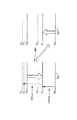
図3(a)は、信号光1の進行方向と同一方向に励起光2を入力する前方励起型の光ファイバ増幅器110の概略構成図である。図3(a)に示すように、光ファイバ増幅器110は、コアにツリウム(Tm)を含有する(好ましくは2000ppmwt以上、より好ましくは3000ppmwt以上)増幅用光ファイバ111の両端側に、光アイソレータ112をそれぞれ接続し、信号光1(1480〜1520nm)の入力側の光アイソレータ112と増幅用光ファイバ111との間に、信号光1と励起光2とを合波する波長分割多重型のカプラ113を接続し、当該カプラ113に、励起光2(1320〜1480nm)を発生する励起光源114を接続した構成となっている。
【0033】
図3(b)は、信号光1の進行方向と逆方向に励起光2を入力する後方励起型の光ファイバ増幅器120の概略構成図である。図3(b)に示すように、光ファイバ増幅器120は、上記光ファイバ増幅器110の信号光1の入力側の光アイソレータ112と増幅用光ファイバ111との間に接続したカプラ113および励起光源114に代えて、信号光1の出力側の光アイソレータ112と増幅用光ファイバ111との間に、カプラ113および励起光源114を接続した構造となっている。
【0034】
図3(c)は、信号光1の進行方向および逆方向の両方向から励起光2を入力する双方向励起型の光ファイバ増幅器130の概略構成図である。図3(c)に示すように、光ファイバ増幅器130は、信号光1の入力側の光アイソレータ112および信号光1の出力側の光アイソレータ112と増幅用光ファイバ111との間に、カプラ113をそれぞれ接続し、これらカプラ113に、励起光源114をそれぞれ接続した構成となっている。
【0035】
前記増幅用光ファイバ111においては、Tmを添加するホストガラスとして、非輻射遷移の起こりにくいフッ化物系ガラス(例えば、ZrF4 やBaF2 やLaF3 等を主成分としたZBLANガラスや、InF2 やBaF2 やPbF2 等を主成分としたIn−Pbガラス)や、TeO2 等を主成分としたテルライトガラス等が適用可能である。
【0036】
このような増幅用光ファイバ111においては、少なくともコアにTmを含有しているので、Tmイオンの誘導放出による遷移を起こさせることができ、S帯での増幅を図ることができる。
【0037】
ここで、増幅用光ファイバ111が少なくともコアにTmを2000ppmwt以上の濃度で含有していると、当該増幅用光ファイバ111の長さを抑制してコンパクト化を図ることができるので好ましい。特に、増幅用光ファイバ111が少なくともコアにTmを3000ppmwt以上の高濃度で含有していると、クロス緩和の影響が顕著に現れ、増幅始準位蛍光寿命を90%以下に減少させることができるので非常に好ましい。なお、上記含有濃度は、現状のガラスやファイバの作製技術の観点から、10wt%以下であると好ましい(より好ましくは6wt%以下)。
【0038】
前記カプラ113としては、融着延伸型、誘電体多層膜型、ファイバグレーティングと組み合わせたサーキュレータ等が適用可能である。
【0039】
前記励起光源114としては、ファイバラマンレーザや、レーザダイオード(LD)等が適用可能である。
【0040】
このような本実施の形態においては、カプラ113、励起光源114などにより励起光入力手段を構成している。
【0041】
このようにして構成される光ファイバ増幅器110,120,130において、ZBLANガラス(Zr系)、In−Pbガラス、テルライトガラスの三種類を前記ホストガラスにそれぞれ用いると共に、Tmを2000ppmwtおよび3000ppmwtの二種類の濃度で各々に添加した増幅用光ファイバ111(合計六種類)をそれぞれ使用して、信号光1(1480〜1520nm)を励起光2(1320〜1480nm)で励起させた場合の変換効率を求めた。その結果を図4に示す。なお、比較のため、従来の励起光(1047nm)を用いた場合も行った。
【0042】
図4からわかるように、すべての種類の増幅用光ファイバ111の前記ホストガラスにおいて、変換効率を高めることができた。特に、Tm濃度が3000ppmwtであると、Tm濃度が2000ppmwtの場合よりも変換効率をさらに高めることができる。
【0043】
ここで、励起光2の波長と変換効率との関係を図5に示す。少なくともコアにTmを含有する増幅用光ファイバ111の変換効率は、励起光2の波長が1320nm以上となると増加し、1400nm付近で最大となり、1520nmを超えるとほとんどなくなってしまう。このため、励起光2の波長としては、1320〜1520nmであると好ましいが、増幅帯域をS帯(1480−1520nm)とするには、1320〜1480nmの範囲であると好ましく、さらに、1370〜1460nmの範囲であると、変換効率を十分な大きさ(2000ppmwtでは20%以上、3000ppmwtでは25%以上)にすることができるので、より好ましい。
【0044】
したがって、本実施の形態によれば、信号光1と同じ1400nm帯の波長の励起光2を使用するので、信号光1の変換効率を高めることができる。
【0045】
[第二番目の実施の形態]
本発明による光ファイバ増幅器の第二番目の実施の形態を図6〜図8を用いて説明する。図6は、光ファイバ増幅器の概略構成図である。ただし、前述した第一番目の実施の形態の場合と同様な部分については、前述した第一番目の実施の形態の場合と同様な符号を用いることにより、その説明を省略する。
【0046】
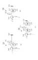
図6(a)は、信号光1の進行方向と同一方向に励起光2および補助励起光3を入力する前方励起型の光ファイバ増幅器210の概略構成図である。図6(a)に示すように、光ファイバ増幅器210は、前述した第一番目の実施の形態の光ファイバ増幅器110において、信号光1の入力側の光アイソレータ112とカプラ113との間A1に、補助カプラ213を接続し、この補助カプラ213に、630〜720nm,740〜830nm,1100〜1300nm、1500〜2000nmの範囲のうちの少なくとも一つの範囲の波長の補助励起光3を発生する補助励起光源214を接続した構成となっている。ここで、630〜720nm,740〜830nm,1100〜1300nm、1500〜2000nmの範囲は、図7に示すようにTmの高吸収範囲である。
【0047】
なお、前方励起型の光ファイバ増幅器210においては、図6(a)に示したように、信号光1の入力側の光アイソレータ112とカプラ113との間A1に、補助カプラ213および補助励起光源214を設けて補助励起光3を信号光1の進行方向と同一方向に入力するようにしたが、これに限らず、カプラ113と増幅用光ファイバ111との間A2に補助カプラ213および補助励起光源214を設けて補助励起光3を信号光1の進行方向と同一方向に入力したり、増幅用光ファイバ111と信号光1の出力側の光アイソレータ112との間Bに補助カプラ213および補助励起光源214を設けて補助励起光3を信号光1の進行方向と逆方向に入力したり、さらにはこれらを各種組み合わせて補助励起光3を入力することも可能である。
【0048】
図6(b)は、信号光1の進行方向と逆方向に励起光2および補助励起光3を入力する後方励起型の光ファイバ増幅器220の概略構成図である。図6(b)に示すように、光ファイバ増幅器220は、前述した第一番目の実施の形態の光ファイバ増幅器120において、信号光1の出力側の光アイソレータ112とカプラ113との間B2に、補助カプラ213を接続し、このカプラ213に、補助励起光源214を接続した構成となっている。
【0049】
なお、後方励起型の光ファイバ増幅器220においては、図6(b)に示したように、信号光1の出力側の光アイソレータ112とカプラ113との間B2に、補助カプラ213および補助励起光源214を設けて補助励起光3を信号光1の進行方向と逆方向に入力するようにしたが、これに限らず、増幅用光ファイバ111とカプラ113との間B1に補助カプラ213および補助励起光源214設けて補助励起光3を信号光1の進行方向と逆方向に入力したり、信号光1の入力側の光アイソレータ112と増幅用光ファイバ111との間Aに補助カプラ213および補助励起光源214設けて補助励起光3を信号光1の進行方向と同一方向に入力したり、さらにはこれらを各種組み合わせて補助励起光3を入力することも可能である。
【0050】
図6(c)は、信号光1の進行方向および逆方向の両方向から励起光2および補助励起光3を入力する双方向励起型の光ファイバ増幅器230の概略構成図である。図6(c)に示すように、光ファイバ増幅器230は、前述した第一番目の実施の形態の光ファイバ増幅器130において、増幅用光ファイバ111と信号光1の入力側の光アイソレータ112および信号光1の出力側の光アイソレータ112との間A2,B1に、補助カプラ213をそれぞれ接続し、これら補助カプラ213に、補助励起光源214をそれぞれ接続した構成となっている。
【0051】
なお、双方向励起型の光ファイバ増幅器230においては、図6(c)に示したように、増幅用光ファイバ111と信号光1の入力側の光アイソレータ112および信号光1の出力側の光アイソレータ112との間A2,B1に、補助カプラ213および補助励起光源214をそれぞれ設けて補助励起光3を信号光1の進行方向および逆方向の両方向から入力するようにしたが、これに限らず、前記間A1,B2を含めて、上記間A1,A2,B1,B2のうちの少なくとも一つに補助カプラ213および補助励起光源214を設けて補助励起光3を入力すればよい。
【0052】
このような本実施の形態では、補助カプラ213、補助励起光源214などにより補助励起光入力手段を構成している。
【0053】
このようにして構成される光ファイバ増幅器210,220,230において、ZBLANガラス(Zr系)、In−Pbガラス、テルライトガラスの三種類を前記ホストガラスにそれぞれ用いると共に、Tmを2000ppmwtおよび3000ppmwtの二種類の濃度で各々に添加した増幅用光ファイバ111(合計六種類)をそれぞれ使用して、信号光1を励起光2および補助励起光3の二波長で励起させた場合の変換効率を求めた。その結果を図8に示す。ただし、励起光2の波長は1415nmとし、補助励起光3の波長は650nm,800nm,1200nm,1560nmの四種をそれぞれ用いた。なお、比較のため、前述した第一番目の実施の形態の場合(励起光2のみの一波長の場合)の結果も併記する。
【0054】
図8からわかるように、すべての種類の増幅用光ファイバ111の前記ホストガラスにおいて、信号光1を励起光2のみの一波長で励起する場合よりも、補助励起光3を併用した二波長の場合の方がS帯での変換効率を高めることができた。特に、Tm濃度が3000ppmwtであると、Tm濃度が2000ppmwtの場合よりもS帯での変換効率をさらに高めることができる。
【0055】
したがって、本実施の形態によれば、1400nm帯の励起光2に加えて、基底準位吸収の大きい波長の補助励起光3を入力するので、前述した第一番目の実施の形態の場合よりも信号光1の変換効率をさらに高めることができる。
【0056】
[第三番目の実施の形態]
本発明による光ファイバ増幅器の第三番目の実施の形態を図9〜図13を用いて説明する。図9は、光ファイバ増幅器の概略構成図である。ただし、前述した第一,二番目の実施の形態の場合と同様な部分については、前述した第一,二番目の実施の形態の場合と同様な符号を用いることにより、その説明を省略する。
【0057】
図9(a)は、信号光1の進行方向と同一方向に励起光2を入力する前方励起型の光ファイバ増幅器310の概略構成図である。図9(a)に示すように、光ファイバ増幅器310は、前述した第一番目の実施の形態の光ファイバ増幅器110において、信号光1の出力側の光アイソレータ112に代えて、信号光1および励起光2のうちの少なくとも信号光1を反射する反射ミラー315を設けると共に、信号光1の入力側の光アイソレータ112に代えて、入力された信号光1と出力される信号光1とを分波する光サーキュレータ316を設けた構成となっている。
【0058】
図9(b)は、信号光1の進行方向と逆方向に励起光2を入力する後方励起型の光ファイバ増幅器320の概略構成図である。図9(b)に示すように、光ファイバ増幅器320は、前述した第一番目の実施の形態の光ファイバ増幅器120において、信号光1の出力側の光アイソレータ112に代えて、反射ミラー315を設けると共に、信号光1の入力側の光アイソレータ112に代えて、光サーキュレータ316を設けた構成となっている。
【0059】
図9(c)は、信号光1の進行方向と同一方向および逆方向に励起光2を入力する双方向励起型の光ファイバ増幅器330の概略構成図である。図9(c)に示すように、光ファイバ増幅器330は、前述した第一番目の実施の形態の光ファイバ増幅器130において、信号光1の出力側の光アイソレータ112に代えて、反射ミラー315を設けると共に、信号光1の入力側の光アイソレータ112に代えて、光サーキュレータ316を設けた構成となっている。
【0060】
このような本実施の形態では、反射ミラー315などにより信号光往復伝播手段を構成している。
【0061】
このように構成される反射型のうちの光ファイバ増幅器330を用いて、信号光1を励起光2で励起させた場合の利得スペクトルを求めた。ここで、増幅用光ファイバ111の前記ホストガラスをZBLANガラス(Zr系)とし、Tmの含有濃度を2000ppmwtおよび6000ppmwtの二種類とし、信号光1の入力パワーを−13dBm/ch(×4ch)とし、一方の励起光源114からの励起光2の波長を1400nmとし、他方の励起光源114からの励起光2の波長を1415nmとし、励起光源114の合計出力パワーを500mWとし、増幅用光ファイバ111の長さをS帯で高利得が得られるように最適化した大きさとした。その結果を図10(2000ppmwtの場合)および図11(6000ppmwtの場合)に示す。なお、比較のため、前述した第一番目の実施の形態(単一透過型)の図3(c)の場合(ただし、増幅用光ファイバ111の長さを16mとした。)の結果も併記する。
【0062】
図10,11に示すように、S帯(1480〜1520nm)において、本実施の形態(反射型)は、前述した第一番目の実施の形態(単一透過型)の場合よりも利得が向上した。特に、Tm濃度が3000ppmwt以上(本例では6000ppmwt)であると、Tm濃度が2000ppmwtの場合よりもS帯での利得をさらに向上させることができると共に、利得の平坦性を向上させることができる。
【0063】
また、前述した第一番目の実施の形態(単一透過型)の場合と本実施の形態(反射型)の場合との増幅用光ファイバ111(Tm濃度:6000ppmwt)の長さとS帯における変換効率との関係も求めた。その結果を図12に示す。なお、信号光1の条件は同一である。
【0064】
図12に示したように、単一透過型は、15.5〜17mのファイバ長において、1480nmと1510nmとでゲインの略一致する特性を得ることができ、反射型は、6〜8mのファイバ長において、1480nmと1510nmとでゲインの略一致する特性を得ることができた。このゲインの略一致するファイバ長における変換効率は、単一通過型が約24%であるのに対し、反射型が約35%であった。
【0065】
本実施の形態の図9(a)〜図9(c)の構成において、反射ミラー315は図13(a)〜図13(f)に示すように様々な形で設けることができる。より詳しくは、図13(a)は垂直に切断した光ファイバの端面に金蒸着を施した反射ミラーを示す。図13(b)は垂直に切断した光ファイバの端面に誘電体多層膜を取り付けた反射ミラーを示す。図13(c)は光ファイバの端面より出射した光を反射してファイバ内に再入射する金属ミラーによる反射ミラーを示す。図13(d)は図13(c)の反射ミラーにおいて光ファイバの端面と金属ミラーの間にファラデーローテータを挿入した反射ミラーを示す。図13(e)は光ファイバの長手方向に周期的屈折率変化を持たせて入射した光をブラッグ反射により反射するファイバグレーティング型反射ミラーを示す。図13(f)は光をループ状の偏波保持光ファイバに伝播させ3dBカプラで再合波するループミラー型反射ミラーを示す。
【0066】
以上のことから、本実施の形態によれば、前述した第一番目の実施の形態の場合よりも信号光1の変換効率をさらに高めることができると言える。
【0067】
[第四番目の実施の形態]
本発明による光ファイバ増幅器の第四番目の実施の形態を図14〜図15を用いて説明する。図14は、光ファイバ増幅器の概略構成図である。ただし、前述した第一〜三番目の実施の形態の場合と同様な部分については、前述した第一〜三番目の実施の形態の場合と同様な符号を用いることにより、その説明を省略する。
【0068】
図14(a)は、信号光1の進行方向と同一方向に励起光2を入力する前方励起型の光ファイバ増幅器410の概略構成図である。図14(a)に示すように、光ファイバ増幅器410は、前述した第三番目の実施の形態の光ファイバ増幅器310において、前記反射ミラー315に代えて、増幅された自然放出光(ASE:Amplified Spontaneous Emission)を透過させる反射ミラー415を設けた構成となっている。
【0069】
図14(b)は、信号光1の進行方向と逆方向に励起光2を入力する後方励起型の光ファイバ増幅器420の概略構成図である。図14(b)に示すように、光ファイバ増幅器420は、前述した第三番目の実施の形態の光ファイバ増幅器320において、前記反射ミラー315に代えて、増幅された自然放出光(ASE)を透過させる反射ミラー415を設けた構成となっている。
【0070】
図14(c)は、信号光1の進行方向と同一方向および逆方向に励起光2を入力する双方向励起型の光ファイバ増幅器430の概略構成図である。図14(c)に示すように、光ファイバ増幅器430は、前述した第三番目の実施の形態の光ファイバ増幅器330において、前記反射ミラー315に代えて、増幅された自然放出光(ASE)を透過させる反射ミラー415を設けた構成となっている。
【0071】
前記反射ミラー415としては、石英ガラスに金属蒸着したタイプ、誘電体多層膜タイプ、ファイバーグレーティングタイプ等が適用可能である。
【0072】
このような本実施の形態では、反射ミラー415などにより信号光往復伝播手段を構成している。
【0073】
このようにして構成される光ファイバ増幅器410,420,430を用いて、信号光1を励起光2で励起させた場合の信号光1のスペクトルを図15に示す。なお、比較のため、信号光1および励起光2のうちの少なくとも信号光1を反射する反射ミラー315を設けた第三番目の実施の形態の光ファイバ増幅器310,320,330を用いた場合のスペクトルも併記する。
【0074】
本実施の形態による光ファイバ増幅器410,420,430を用いると(図15(a)参照)、第三番目の実施の形態の光ファイバ増幅器310,320,33を用いた場合(図15(b)参照)よりも、信号対雑音比が大きく、雑音特性に優れると共に、ASEによる励起光2の浪費が減少するため、信号光1の出力が増大する。
【0075】
したがって、本実施の形態によれば、前述した第三番目の実施の形態の場合よりも信号光1の変換効率をさらに高めることができる。
【0076】
[第五番目の実施の形態]
本発明による光ファイバ増幅器の第五番目の実施の形態を図16を用いて説明する。図16は、光ファイバ増幅器の概略構成図である。ただし、前述した第一〜四番目の実施の形態の場合と同様な部分については、前述した第一〜四番目の実施の形態の場合と同様な符号を用いることにより、その説明を省略する。
【0077】
図16(a)は、信号光1の進行方向と同一方向に励起光2を入力する前方励起型の光ファイバ増幅器510の概略構成図である。図16(a)に示すように、光ファイバ増幅器510は、前述した第二番目の実施の形態の光ファイバ増幅器210において、信号光1の出力側の光アイソレータ112に代えて、前述した第三番目の実施の形態の光ファイバ増幅器310で用いた反射ミラー315を設けると共に、信号光1の入力側の光アイソレータ112に代えて、前述した第三番目の実施の形態の光ファイバ増幅器310で用いた光サーキュレータ316を設けた構成となっている。
【0078】
図16(b)は、信号光1の進行方向と逆方向に励起光2を入力する後方励起型の光ファイバ増幅器520の概略構成図である。図16(b)に示すように、光ファイバ増幅器520は、前述した第二番目の実施の形態の光ファイバ増幅器220において、信号光1の出力側の光アイソレータ112に代えて前記反射ミラー315を設けると共に、信号光1の入力側の光アイソレータ112に代えて前記光サーキュレータ316を設けた構成となっている。
【0079】
図16(c)は、信号光1の進行方向と同一方向および逆方向に励起光2を入力する双方向励起型の光ファイバ増幅器530の概略構成図である。図16(c)に示すように、光ファイバ増幅器530は、前述した第二番目の実施の形態の光ファイバ増幅器230において、信号光1の出力側の光アイソレータ112に代えて前記反射ミラー315を設けると共に、信号光1の入力側の光アイソレータ112に代えて前記光サーキュレータ316を設けた構成となっている。
【0080】
つまり、本実施の形態による光ファイバ増幅器510,520,530は、前述した第二番目の実施の形態による光ファイバ増幅器210,220,230の特徴と第三番目の実施の形態による光ファイバ増幅器310,320,330の特徴とを併せ持つ構成となっているのである。
【0081】
したがって、本実施の形態によれば、前述した第二番目の実施の形態で得られる効果と第三番目の実施の形態で得られる効果とを併せて得ることができるので、信号光1の変換効率をさらに高めることができる。
【0082】
[第六番目の実施の形態]
本発明による光ファイバ増幅器の第六番目の実施の形態を図17を用いて説明する。図17は、光ファイバ増幅器の概略構成図である。ただし、前述した第一〜五番目の実施の形態の場合と同様な部分については、前述した第一〜五番目の実施の形態の場合と同様な符号を用いることにより、その説明を省略する。
【0083】
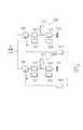
図17は、信号光1の進行方向と同一方向および逆方向に励起光2を入力する双方向励起型の光ファイバ増幅器630の概略構成図である。図17に示すように、光ファイバ増幅器630は、前述した第一番目の実施の形態の光ファイバ増幅器130を直列に二つ接続した二段構成、すなわち、増幅用光ファイバ111を直列に複数接続すると共に、これら増幅用光ファイバ111にカプラ113を介して励起光源114をそれぞれ接続した構成となっている。ただし、信号光1を入力される前段側の光ファイバ増幅器130の出力側の光アイソレータ112と、信号光1を出力する後段側の光ファイバ増幅器130の入力側の光アイソレータ112とは、単一の光アイソレータ112で兼用している。
【0084】
このようにして構成された光ファイバ増幅器630においては、前段側の光ファイバ増幅器130で増幅された信号光1を後段側の光ファイバ増幅器130でさらに増幅して出力することができる。
【0085】
したがって、本実施の形態によれば、前述した第一番目の実施の形態の場合よりも、さらに高利得の信号光増幅と高出力化が可能となる。
【0086】
なお、本実施の形態では、二つの双方向励起型の光ファイバ増幅器130を直列に接続した構成としたが、前段側および後段側の少なくとも一方を前方励起型の光ファイバ増幅器110または後方励起型の光ファイバ増幅器120に代えることも可能である。
【0087】
[第七番目の実施の形態]
本発明による光ファイバ増幅器の第七番目の実施の形態を図18を用いて説明する。図18は、光ファイバ増幅器の概略構成図である。ただし、前述した第一〜六番目の実施の形態の場合と同様な部分については、前述した第一〜六番目の実施の形態の場合と同様な符号を用いることにより、その説明を省略する。
【0088】
図18は、信号光1の進行方向と同一方向および逆方向に励起光2を入力する双方向励起型の光ファイバ増幅器730の概略構成図である。図18に示すように、光ファイバ増幅器730は、前述した第三番目の実施の形態の光ファイバ増幅器330を直列に二つ接続した二段構成、すなわち、増幅用光ファイバ111を直列に複数接続すると共に、これら増幅用光ファイバ111にカプラ113を介して励起光源114をそれぞれ接続した構成となっている。
【0089】
このようにして構成された光ファイバ増幅器730においては、前段側の光ファイバ増幅器330で増幅された信号光1を後段側の光ファイバ増幅器330でさらに増幅して出力することができる。
【0090】
したがって、本実施の形態によれば、前述した第三番目の実施の形態の場合よりも、さらに高利得の信号光増幅と高出力化が可能となる。さらに、前段側の光ファイバ増幅器330から出力される信号光1を数dBm以内に抑えることにより、後段側の光ファイバ増幅器330の増幅用ファイバ111の前端部分の反転分布状態を高くすることができるので、雑音指数の低下を抑えることができる。
【0091】
なお、本実施の形態では、二つの双方向励起型の光ファイバ増幅器330を直列に接続した構成としたが、前段側および後段側の少なくとも一方を前方励起型の光ファイバ増幅器310または後方励起型の光ファイバ増幅器320に代えることも可能である。
【0092】
[第八番目の実施の形態]
本発明による光ファイバ増幅器の第八番目の実施の形態を図19を用いて説明する。図19は、光ファイバ増幅器の概略構成図である。ただし、前述した第一〜七番目の実施の形態の場合と同様な部分については、前述した第一〜七番目の実施の形態の場合と同様な符号を用いることにより、その説明を省略する。
【0093】
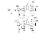
図19は、信号光1の進行方向と同一方向および逆方向に励起光2を入力する双方向励起型の光ファイバ増幅器830の概略構成図である。図19に示すように、光ファイバ増幅器830は、前述した第七番目の実施の形態の光ファイバ増幅器730の前段側の光ファイバ増幅器330と後段側の光ファイバ増幅器330との間に、利得等化器817を接続した構成となっている。
【0094】
このようにして構成された光ファイバ増幅器830においては、前段側の光ファイバ増幅器330で増幅された信号光1が利得等化器817により平坦な利得特性に等化された後に後段側の光ファイバ増幅器330でさらに増幅されて出力されるようになる。
【0095】
したがって、本実施の形態によれば、前述した第七番目の実施の形態の場合よりも、1480〜1520nmの帯域で利得特性を等化して増幅した信号光1を出力することができる。
【0096】
なお、本実施の形態では、二つの双方向励起型の光ファイバ増幅器330を直列に接続した構成としたが、前段側および後段側の少なくとも一方を前方励起型の光ファイバ増幅器310または後方励起型の光ファイバ増幅器320に代えることも可能である。
【0097】
また、本実施の形態では、利得等化器817を一つ用いたが、複数設けることも可能である。
【0098】
[第九番目の実施の形態]
本発明による光ファイバ増幅器の第九番目の実施の形態を図20〜図27を用いて説明する。図20〜図27は、光ファイバ増幅器の概略構成図である。ただし、前述した第一〜八番目の実施の形態の場合と同様な部分については、前述した第一〜八番目の実施の形態の場合と同様な符号を用いることにより、その説明を省略する。
【0099】
前述した第六〜八番目の実施の形態では、増幅用光ファイバ111を直列に複数接続すると共に、これら増幅用光ファイバ111にカプラ113を介して励起光源114をそれぞれ接続した。これに対し、本実施の形態では、複数の増幅用光ファイバ111を光合分波器を介して並列に接続する。このようにしても、信号光の増幅および高出力化を図ることが可能である。
【0100】
より詳しくは、図20は、信号光1の進行方向および逆方向の両方向から励起光2を入力する双方向励起型の光ファイバ増幅器の概略構成図であり、前述した第一番目の実施の形態の光ファイバ増幅器130を二つ並列に接続したものである。
【0101】
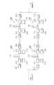
図21は、信号光1の進行方向および逆方向の両方向から励起光2を入力する双方向励起型の光ファイバ増幅器の概略構成図であり、前述した第一番目の実施の形態の光ファイバ増幅器130を二つ直列に接続したもの二組を並列に接続したものである。
【0102】
図22は、信号光1の進行方向および逆方向の両方向から励起光2を入力する双方向励起型の光ファイバ増幅器の概略構成図であり、前述した第一番目の実施の形態の光ファイバ増幅器130を二つ並列に接続し、二つの利得等化器817をこれら二つの光ファイバ増幅器130の出力側に各々設けたものである。
【0103】
図23は、信号光1の進行方向および逆方向の両方向から励起光2を入力する双方向励起型の光ファイバ増幅器の概略構成図であり、前述した第一番目の実施の形態の光ファイバ増幅器130を二つ直列に接続したもの二組を並列に接続し、二つの利得等化器817をこれら二つの光ファイバ増幅器130二組の各々における前段側の光ファイバ増幅器と後段側の光ファイバ増幅器の間に各々設けたものである。
【0104】
図24は、信号光1の進行方向および逆方向の両方向から励起光2を入力する双方向励起型の光ファイバ増幅器の概略構成図であり、前述した第三番目の実施の形態の光ファイバ増幅器330を二つ並列に接続したものである。
【0105】
図25は、信号光1の進行方向および逆方向の両方向から励起光2を入力する双方向励起型の光ファイバ増幅器の概略構成図であり、前述した第三番目の実施の形態の光ファイバ増幅器330を二つ直列に接続したもの二組を並列に接続したものである。
【0106】
図26は、信号光1の進行方向および逆方向の両方向から励起光2を入力する双方向励起型の光ファイバ増幅器の概略構成図であり、前述した第三番目の実施の形態の光ファイバ増幅器330を二つ並列に接続し、二つの利得等化器817をこれら二つの光ファイバ増幅器330の出力側に各々設けたものである。
【0107】
図27は、信号光1の進行方向および逆方向の両方向から励起光2を入力する双方向励起型の光ファイバ増幅器の概略構成図であり、前述した第三の実施の形態の光ファイバ増幅器330を二つ直列に接続したもの二組を並列に接続し、二つの利得等化器817をこれら二つの光ファイバ増幅器330二組の各々における前段側の光ファイバ増幅器と後段側の光ファイバ増幅器の間に各々設けたものである。
【0108】
[他の実施の形態]
なお、前述した第一〜九番目の各実施の形態においては、信号光1と励起光2とを分波させるカプラを設けることも可能である。
【0109】
また、前述した第一〜九番目の各実施の形態では、コアにTmを含有する増幅用光ファイバ111を用いたが、これに代えて、コアおよびクラッドにTmを含有する増幅用光ファイバを用いることも可能であり、少なくともコアにTmを含有する増幅用光ファイバであれば、前述した第一〜九番目の各実施の形態の場合と同様な効果を得ることができる。
【0110】
【発明の効果】
以上説明したように、本発明による光ファイバ増幅器は、LDにより発光可能で信号光の波長帯と同じ1400nm帯の波長の励起光を利用して信号光を励起するようにしたので、3H4 からのESA(Excited State Absorption)の発生を抑制することができ、S帯における高効率化、小型化、低コスト化を図ることができる。また、反射型や二波長励起型とすることにより、さらなる高効率化が可能である。
【図面の簡単な説明】
【図1】従来の二波長励起TDFAの動作原理を説明するエネルギー準位図である。
【図2】従来の高濃度TDFAの動作原理を説明するエネルギー準位図である。
【図3】本発明の第一番目の実施の形態による前方励起型、後方励起型、双方向励起型の光ファイバ増幅器の概略構成図である。
【図4】第一番目の実施の形態の光ファイバ増幅器および従来の光ファイバ増幅器により求められた変換効率を示す表である。
【図5】第一番目の実施の形態の光ファイバ増幅器における励起光の波長と変換効率との関係を表すグラフである。
【図6】本発明の第二番目の実施の形態による前方励起型、後方励起型、双方向励起型の光ファイバ増幅器の概略構成図である。
【図7】第二番目の実施の形態の光ファイバ増幅器で利用するツリウムの吸収スペクトルを表すグラフである。
【図8】第二番目の実施の形態の光ファイバ増幅器および第一番目の実施の形態の光ファイバ増幅器により求められた変換効率を示す表である。
【図9】本発明の第三番目の実施の形態による前方励起型、後方励起型、双方向励起型の光ファイバ増幅器の概略構成図である。
【図10】図3(c)および図9(c)の光ファイバ増幅器において、Tmを2000ppmwt含有する増幅用光ファイバを用いた場合の利得スペクトルを表すグラフである。
【図11】図3(c)および図9(c)の光ファイバ増幅器において、Tmを6000ppmwt含有する増幅用光ファイバを用いた場合の利得スペクトルを表すグラフである。
【図12】第三番目の実施の形態の光ファイバ増幅器における増幅用光ファイバの長さと変換効率との関係を表すグラフである。
【図13】第三番目の実施の形態の光ファイバ増幅器において使用できる反射ミラーの形を示す図である。
【図14】本発明の第四番目の実施の形態による前方励起型、後方励起型、双方向励起型の光ファイバ増幅器の概略構成図である。
【図15】第四番目の実施の形態の光ファイバ増幅器および第三番目の実施の形態の光ファイバ増幅器における信号光スペクトルを表すグラフである。
【図16】本発明の第五番目の実施の形態による前方励起型、後方励起型、双方向励起型の光ファイバ増幅器の概略構成図である。
【図17】本発明の第六番目の実施の形態による光ファイバ増幅器の概略構成図である。
【図18】本発明の第七番目の実施の形態による光ファイバ増幅器の概略構成図である。
【図19】本発明の第八番目の実施の形態による光ファイバ増幅器の概略構成図である。
【図20】本発明の第九番目の実施の形態による光ファイバ増幅器の一例の概略構成図である。
【図21】本発明の第九番目の実施の形態による光ファイバ増幅器の他の例の概略構成図である。
【図22】本発明の第九番目の実施の形態による光ファイバ増幅器の他の例の概略構成図である。
【図23】本発明の第九番目の実施の形態による光ファイバ増幅器の他の例の概略構成図である。
【図24】本発明の第九番目の実施の形態による光ファイバ増幅器の他の例の概略構成図である。
【図25】本発明の第九番目の実施の形態による光ファイバ増幅器の他の例の概略構成図である。
【図26】本発明の第九番目の実施の形態による光ファイバ増幅器の他の例の概略構成図である。
【図27】本発明の第九番目の実施の形態による光ファイバ増幅器の他の例の概略構成図である。
【符号の説明】
1 信号光
2 励起光
3 補助励起光
110,120,130 光ファイバ増幅器
111 増幅用光ファイバ
112 光アイソレータ
113 カプラ
114 励起光源
210,220,230 光ファイバ増幅器
213 補助カプラ
214 補助励起光源
310,320,330 光ファイバ増幅器
315 反射ミラー
316 光サーキュレータ
410,420,430 光ファイバ増幅器
415 反射ミラー
510,520,530,630,730,830 光ファイバ増幅器
817 利得等化器[0001]
BACKGROUND OF THE INVENTION
The present invention relates to an optical fiber amplifier having an amplification band at 1480 to 1520 nm, which is a low loss region of an optical fiber, and a broadband optical fiber amplifier including the same.
[0002]
[Prior art]
With the spread of the Internet and the like, the communication capacity is rapidly increasing, so that a communication system using a wavelength division multiplexing (WDM) system has begun to be applied so as to cope with an increase in the capacity of an optical communication system. . In this WDM system, it is essential to use an erbium-doped fiber amplifier (EDFA) as a repeater, and an amplifier band (1.53 to 1.60 μm) of the EDFA is used. It has been put into practical use.
[0003]
However, in order to cope with further increase in capacity of communication equipment, it is necessary to expand the amplification band of the optical fiber amplifier so that the low loss region (1.45-1.65 μm) of the silica fiber can be covered. Development of a new optical fiber amplifier is strongly desired.
[0004]
For this reason, development of an optical fiber amplifier adapted to the S band (1480 to 1520 nm) having low loss and low dispersion of a silica fiber equivalent to the C band (1530 to 1560 nm) already in practical use has been carried out. It has been broken. There are currently three types of S-band optical fiber amplifiers.
[0005]
The first is a Raman optical fiber amplifier that utilizes stimulated Raman scattering that occurs when signal light is input to the silica fiber in a state where strong excitation light is input to the silica fiber (for example, J. Kani et al. al., Electronics Letters, Vol.34, No.18,
pp. 1745-1747, 1998).
[0006]
The second is S+ Of an up-
[0007]
FIG. 1A shows the Tm energy level and the amplification state of the two-wavelength excitation TDFA. For S-band amplification,3 H4 From3 F4 Use stimulated release. In the case of two-wavelength excitation, the ground level is obtained by excitation light of 1560 nm.3 H6 To the final level of amplification3 F4 And then the final level of the amplification by the 1000 nm band excitation light.3 F4 To the starting level of amplification3 F2 Excited to By controlling the power of the excitation light of two wavelengths, Tm ions (Tm at each level)3+ ) Control the number to form a low population inversion, S+ The TDFA amplification band of the band is shifted to the S band.
[0008]
Furthermore, as shown in FIG.3 F4 Starting level from3 F2 A high-efficiency S-band optical fiber amplifier can be realized by changing the excitation wavelength to 1000 nm band from the 1400 nm band to a high pumping efficiency (for example, T. Kasamatsu et al., Electronics Letters, Vol. 36). No. 19, pp. 1607-1609, 2000).
[0009]
Third, in an up-
[0010]
FIG. 2 shows the Tm energy level and the amplification state of the high concentration TDFA. Ground level by 1000nm excitation light3 H6 To the final level of amplification3 F4 Once excited, the final level of amplification is further increased by the excitation light of the same wavelength.3 F4 To the starting level of amplification3 F2 Excited to
[0011]
By the way, low concentration TDFA is the final level of amplification.3 F4 To the starting level of amplification3 F2 Tm for excitation light when excited to3+ Absorption of the ground level3 H6 To the final level of amplification3 F4 Tm for excitation light when excited to3+ Therefore, a high inversion distribution is formed.
[0012]
Such a low concentration TDFA reflects the high inversion distribution state as described above.+ In addition to having the main amplification band in the band, the amplification operation can be realized even in the S band, although it is out of the peak wavelength of the gain spectrum. The amplification efficiency in the S band due to the low concentration TDFA is equal to or less than that of the high concentration TDFA.
[0013]
In contrast, high concentration TDFA is3+ As shown in FIG. 2, the starting level of amplification3 F2 Tm excited to3+ Is the ground level3 H6 Tm nearby3+ The final level of amplification by causing energy transfer to3 F4 Tm that received energy while relaxing3+ Is the final level of amplification3 F4 Excited to As a result, the final level of amplification3 F4 Tm excited to3+ The number increases, a low inversion distribution is formed, and a gain shift occurs.
[0014]
[Problems to be solved by the invention]
However, in the high concentration TDFA as described above, a laser diode (LD) that emits a 1000 nm wavelength band used for excitation light has not been developed. The efficiency was not very good (about 5%), and there were difficulties in practical use.
[0015]
In addition, even in low-concentration TDFAs, a laser diode (LD) that emits a 1000 nm wavelength band used for excitation light has not been developed, so it is difficult not only to reduce cost and size, but also to convert in the S band. Since the efficiency is equal to or less than that of the high concentration TDFA, there is a difficulty in practical use.
[0016]
Accordingly, an object of the present invention is to provide an optical fiber amplifier with high conversion efficiency that can use pumping light in a wavelength band that can be emitted by an LD.
[0017]
[Means for Solving the Problems]
The present invention is to solve the above-mentioned problems. Amplifying optical fiber containing signal light and containing at least thulium in the core, and pumping light input means for inputting at least one pumping light having a wavelength of 1320 to 1520 nm into the amplifying optical fiber, An optical fiber amplifier is provided.
[0018]
In the present invention, the pumping light input means inputs at least one pumping light having a wavelength of 1320 to 1480 nm to the amplification optical fiber.
[0019]
In the present invention, the excitation light input means inputs at least one excitation light having a wavelength of 1370 to 1460 nm to the amplification optical fiber.
[0020]
In the present invention, the amplification optical fiber contains at least 2000 ppmwt of thulium in the core.
[0021]
In the present invention, the amplification optical fiber contains 3000 ppmwt or more of thulium in at least the core.
[0022]
In the present invention, at least one auxiliary excitation light having a wavelength within at least one of the ranges of 630 to 720 nm, 740 to 830 nm, 1100 to 1300 nm, and 1500 to 2000 nm is input to the amplification optical fiber. It further has auxiliary excitation light input means.
[0023]
The present invention is further characterized by further comprising signal light round-trip propagation means for round-trip propagation of the signal light in the amplification optical fiber.
[0024]
In the present invention, the signal light round-trip propagation means is a reflection mirror provided at one end of the amplification optical fiber.
[0025]
In the present invention, the signal light reciprocating propagation means reciprocally propagates only the signal light or only the signal light and the at least one pumping light in the amplification optical fiber.
[0026]
In the present invention, the signal light round-trip propagation means transmits amplified spontaneous emission light.
[0027]
The present invention is further characterized by further comprising an optical isolator or an optical circulator that is connected to the amplification optical fiber and propagates the signal light in only one direction within the amplification optical fiber.
[0028]
Furthermore, the present invention relates to a plurality of amplification optical fibers each receiving signal light, each containing at least thulium in the core and connected in series or in parallel, and each corresponding to the amplification
[0029]
The present invention is further characterized by further comprising at least one gain equalizer connected to the amplification optical fiber.
[0030]
DETAILED DESCRIPTION OF THE INVENTION
Embodiments of the optical fiber amplifier according to the present invention will be described below, but the present invention is not limited to these embodiments.
[0031]
[First embodiment]
A first embodiment of an optical fiber amplifier according to the present invention will be described with reference to FIGS. FIG. 3 is a schematic configuration diagram of an optical fiber amplifier.
[0032]
FIG. 3A is a schematic configuration diagram of a forward pumping type
[0033]
FIG. 3B is a schematic configuration diagram of the backward pumping type
[0034]
FIG. 3C is a schematic configuration diagram of a bidirectional pumping type
[0035]
In the amplification
[0036]
In such an amplification
[0037]
Here, it is preferable that the amplification
[0038]
As the
[0039]
As the
[0040]
In the present embodiment, the
[0041]
In the
[0042]
As can be seen from FIG. 4, in the host glass of all types of amplification
[0043]
Here, the relationship between the wavelength of the
[0044]
Therefore, according to the present embodiment, the pumping
[0045]
[Second embodiment]
A second embodiment of the optical fiber amplifier according to the present invention will be described with reference to FIGS. FIG. 6 is a schematic configuration diagram of an optical fiber amplifier. However, the same parts as those of the first embodiment described above are denoted by the same reference numerals as those of the first embodiment described above, and the description thereof is omitted.
[0046]
FIG. 6A is a schematic configuration diagram of a forward pumping type
[0047]
In the forward pumping type
[0048]
FIG. 6B is a schematic configuration diagram of a backward pumping type
[0049]
In the backward pumping type
[0050]
FIG. 6C is a schematic configuration diagram of a bidirectional pumping type
[0051]
In the bidirectional pumping type
[0052]
In this embodiment, auxiliary pumping light input means is constituted by the
[0053]
In the
[0054]
As can be seen from FIG. 8, in the host glasses of all types of amplification
[0055]
Therefore, according to the present embodiment, since the auxiliary excitation light 3 having a wavelength having a large ground level absorption is input in addition to the
[0056]
[Third embodiment]
A third embodiment of the optical fiber amplifier according to the present invention will be described with reference to FIGS. FIG. 9 is a schematic configuration diagram of an optical fiber amplifier. However, the same parts as those of the first and second embodiments described above are denoted by the same reference numerals as those of the first and second embodiments, and the description thereof is omitted.
[0057]
FIG. 9A is a schematic configuration diagram of a forward pumping type
[0058]
FIG. 9B is a schematic configuration diagram of a backward pumping type
[0059]
FIG. 9C is a schematic configuration diagram of a bidirectional pumping type
[0060]
In this embodiment, the signal light round-trip propagation means is constituted by the
[0061]
Using the reflection type
[0062]
As shown in FIGS. 10 and 11, in the S band (1480 to 1520 nm), the present embodiment (reflection type) has an improved gain over the case of the first embodiment (single transmission type) described above. did. In particular, when the Tm concentration is 3000 ppmwt or more (in this example, 6000 ppmwt), the gain in the S band can be further improved and the flatness of the gain can be improved as compared with the case where the Tm concentration is 2000 ppmwt.
[0063]
Further, the length of the amplification optical fiber 111 (Tm concentration: 6000 ppmwt) and the conversion in the S band in the case of the first embodiment (single transmission type) and the case of the present embodiment (reflection type) described above. The relationship with efficiency was also sought. The result is shown in FIG. The conditions of the
[0064]
As shown in FIG. 12, the single-transmission type can obtain characteristics with substantially matching gains at 1480 nm and 1510 nm at a fiber length of 15.5 to 17 m, and the reflection type is a fiber of 6 to 8 m. In terms of length, it was possible to obtain characteristics with substantially matching gains at 1480 nm and 1510 nm. The conversion efficiency in the fiber lengths having substantially the same gain is about 24% for the single-pass type and about 35% for the reflective type.
[0065]
In the configuration of FIGS. 9A to 9C of the present embodiment, the
[0066]
From the above, it can be said that according to the present embodiment, the conversion efficiency of the
[0067]
[Fourth embodiment]
A fourth embodiment of the optical fiber amplifier according to the present invention will be described with reference to FIGS. FIG. 14 is a schematic configuration diagram of an optical fiber amplifier. However, the same parts as those in the first to third embodiments described above are denoted by the same reference numerals as those in the first to third embodiments, and the description thereof is omitted.
[0068]
FIG. 14A is a schematic configuration diagram of a forward pumping type
[0069]
FIG. 14B is a schematic configuration diagram of a backward pumping type
[0070]
FIG. 14C is a schematic configuration diagram of a bidirectional pumping type
[0071]
As the
[0072]
In this embodiment, the signal light round-trip propagation means is configured by the
[0073]
FIG. 15 shows the spectrum of the
[0074]
When the
[0075]
Therefore, according to the present embodiment, it is possible to further increase the conversion efficiency of the
[0076]
[Fifth embodiment]
A fifth embodiment of the optical fiber amplifier according to the present invention will be described with reference to FIG. FIG. 16 is a schematic configuration diagram of an optical fiber amplifier. However, the same parts as those of the first to fourth embodiments described above are denoted by the same reference numerals as those of the first to fourth embodiments, and the description thereof is omitted.
[0077]
FIG. 16A is a schematic configuration diagram of a forward pumping type
[0078]
FIG. 16B is a schematic configuration diagram of a backward pumping type optical fiber amplifier 520 that inputs the
[0079]
FIG. 16C is a schematic configuration diagram of a bidirectionally pumped
[0080]
That is, the
[0081]
Therefore, according to the present embodiment, the effect obtained in the second embodiment and the effect obtained in the third embodiment can be obtained together. Efficiency can be further increased.
[0082]
[Sixth embodiment]
A sixth embodiment of the optical fiber amplifier according to the present invention will be described with reference to FIG. FIG. 17 is a schematic configuration diagram of an optical fiber amplifier. However, the same parts as those of the first to fifth embodiments described above are denoted by the same reference numerals as those of the first to fifth embodiments, and the description thereof is omitted.
[0083]
FIG. 17 is a schematic configuration diagram of a bidirectional pumping type
[0084]
In the
[0085]
Therefore, according to the present embodiment, it is possible to further amplify the signal light with higher gain and increase the output than in the case of the first embodiment described above.
[0086]
In the present embodiment, two bidirectional pumping type
[0087]
[Seventh embodiment]
A seventh embodiment of the optical fiber amplifier according to the present invention will be described with reference to FIG. FIG. 18 is a schematic configuration diagram of an optical fiber amplifier. However, the same parts as those of the first to sixth embodiments described above are denoted by the same reference numerals as those of the first to sixth embodiments, and the description thereof is omitted.
[0088]
FIG. 18 is a schematic configuration diagram of a bidirectional pumping type
[0089]
In the
[0090]
Therefore, according to the present embodiment, it is possible to perform signal light amplification and higher output with higher gain than in the case of the third embodiment described above. Further, by suppressing the
[0091]
In the present embodiment, two bidirectional pumping type
[0092]
[Eighth embodiment]
An eighth embodiment of the optical fiber amplifier according to the present invention will be described with reference to FIG. FIG. 19 is a schematic configuration diagram of an optical fiber amplifier. However, the same parts as those of the first to seventh embodiments described above are denoted by the same reference numerals as those of the first to seventh embodiments, and the description thereof is omitted.
[0093]
FIG. 19 is a schematic configuration diagram of a bidirectional pumping type
[0094]
In the
[0095]
Therefore, according to the present embodiment, it is possible to output the amplified
[0096]
In the present embodiment, two bidirectional pumping type
[0097]
In this embodiment, one
[0098]
[Ninth embodiment]
A ninth embodiment of the optical fiber amplifier according to the present invention will be described with reference to FIGS. 20 to 27 are schematic configuration diagrams of the optical fiber amplifier. However, the same parts as those of the first to eighth embodiments described above are denoted by the same reference numerals as those of the first to eighth embodiments, and the description thereof is omitted.
[0099]
In the sixth to eighth embodiments described above, a plurality of amplification
[0100]
More specifically, FIG. 20 is a schematic configuration diagram of a bidirectional pumping type optical fiber amplifier that inputs the pumping light 2 from both the traveling direction and the reverse direction of the
[0101]
FIG. 21 is a schematic configuration diagram of a bidirectional pumping type optical fiber amplifier that inputs the pumping light 2 from both the traveling direction and the reverse direction of the
[0102]
FIG. 22 is a schematic configuration diagram of a bidirectional pumping type optical fiber amplifier that inputs the pumping light 2 from both the traveling direction and the reverse direction of the
[0103]
FIG. 23 is a schematic configuration diagram of a bidirectional pumping type optical fiber amplifier that inputs the pumping light 2 from both the traveling direction and the reverse direction of the
[0104]
FIG. 24 is a schematic configuration diagram of a bidirectional pumping type optical fiber amplifier that inputs the pumping light 2 from both the traveling direction and the reverse direction of the
[0105]
FIG. 25 is a schematic configuration diagram of a bidirectional pumping type optical fiber amplifier that inputs the pumping light 2 from both the traveling direction and the reverse direction of the
[0106]
FIG. 26 is a schematic configuration diagram of a bidirectional pumping type optical fiber amplifier that inputs the pumping light 2 from both the traveling direction and the reverse direction of the
[0107]
FIG. 27 is a schematic configuration diagram of a bidirectional pumping type optical fiber amplifier that inputs the pumping light 2 from both the traveling direction and the reverse direction of the
[0108]
[Other embodiments]
In each of the first to ninth embodiments described above, it is possible to provide a coupler that demultiplexes the
[0109]
In each of the first to ninth embodiments described above, the amplification
[0110]
【The invention's effect】
As described above, the optical fiber amplifier according to the present invention is configured to excite the signal light by using the excitation light having the wavelength of 1400 nm which is the same as the wavelength band of the signal light that can be emitted by the LD.3 H4 ESA (Excited State Absorption) can be suppressed, and high efficiency, downsizing, and cost reduction in the S band can be achieved. Further, by using a reflection type or a two-wavelength excitation type, higher efficiency can be achieved.
[Brief description of the drawings]
FIG. 1 is an energy level diagram illustrating the operating principle of a conventional dual wavelength excitation TDFA.
FIG. 2 is an energy level diagram for explaining the operating principle of a conventional high-concentration TDFA.
FIG. 3 is a schematic configuration diagram of a forward pumping type, a backward pumping type, and a bidirectional pumping type optical fiber amplifier according to a first embodiment of the present invention.
FIG. 4 is a table showing conversion efficiencies obtained by the optical fiber amplifier of the first embodiment and the conventional optical fiber amplifier.
FIG. 5 is a graph showing the relationship between the wavelength of pumping light and the conversion efficiency in the optical fiber amplifier according to the first embodiment.
FIG. 6 is a schematic configuration diagram of a forward pumping type, a backward pumping type, and a bidirectional pumping type optical fiber amplifier according to a second embodiment of the present invention.
FIG. 7 is a graph showing an absorption spectrum of thulium used in the optical fiber amplifier according to the second embodiment.
FIG. 8 is a table showing conversion efficiencies determined by the optical fiber amplifier of the second embodiment and the optical fiber amplifier of the first embodiment.
FIG. 9 is a schematic configuration diagram of a forward pumping type, a backward pumping type, and a bidirectional pumping type optical fiber amplifier according to a third embodiment of the present invention.
FIG. 10 is a graph showing a gain spectrum when an optical fiber for amplification containing 2000 ppmwt of Tm is used in the optical fiber amplifiers of FIGS. 3 (c) and 9 (c).
11 is a graph showing a gain spectrum when an amplification optical fiber containing 6000 ppmwt of Tm is used in the optical fiber amplifiers of FIGS. 3 (c) and 9 (c). FIG.
FIG. 12 is a graph showing the relationship between the length of the amplification optical fiber and the conversion efficiency in the optical fiber amplifier according to the third embodiment.
FIG. 13 is a diagram showing the shape of a reflection mirror that can be used in the optical fiber amplifier according to the third embodiment.
FIG. 14 is a schematic configuration diagram of a forward pumping type, a backward pumping type, and a bidirectional pumping type optical fiber amplifier according to a fourth embodiment of the present invention.
FIG. 15 is a graph showing signal light spectra in the optical fiber amplifier according to the fourth embodiment and the optical fiber amplifier according to the third embodiment.
FIG. 16 is a schematic configuration diagram of a forward pumping type, backward pumping type, and bidirectional pumping type optical fiber amplifier according to a fifth embodiment of the present invention.
FIG. 17 is a schematic configuration diagram of an optical fiber amplifier according to a sixth embodiment of the present invention.
FIG. 18 is a schematic configuration diagram of an optical fiber amplifier according to a seventh embodiment of the present invention.
FIG. 19 is a schematic configuration diagram of an optical fiber amplifier according to an eighth embodiment of the present invention.
FIG. 20 is a schematic configuration diagram of an example of an optical fiber amplifier according to a ninth embodiment of the invention.
FIG. 21 is a schematic configuration diagram of another example of the optical fiber amplifier according to the ninth embodiment of the present invention.
FIG. 22 is a schematic configuration diagram of another example of the optical fiber amplifier according to the ninth embodiment of the present invention.
FIG. 23 is a schematic configuration diagram of another example of the optical fiber amplifier according to the ninth embodiment of the present invention.
FIG. 24 is a schematic configuration diagram of another example of the optical fiber amplifier according to the ninth embodiment of the present invention.
FIG. 25 is a schematic configuration diagram of another example of the optical fiber amplifier according to the ninth embodiment of the present invention.
FIG. 26 is a schematic configuration diagram of another example of the optical fiber amplifier according to the ninth embodiment of the present invention.
FIG. 27 is a schematic configuration diagram of another example of the optical fiber amplifier according to the ninth embodiment of the present invention.
[Explanation of symbols]
1 signal light
2 Excitation light
3 Auxiliary excitation light
110, 120, 130 Optical fiber amplifier
111 Optical fiber for amplification
112 Optical isolator
113 coupler
114 Excitation light source
210, 220, 230 Optical fiber amplifier
213 Auxiliary coupler
214 Auxiliary excitation light source
310, 320, 330 Optical fiber amplifier
315 reflection mirror
316 Optical circulator
410, 420, 430 Optical fiber amplifier
415 Reflective mirror
510, 520, 530, 630, 730, 830 Optical fiber amplifier
817 Gain equalizer
Claims (13)
Translated fromJapanese前記増幅用光ファイバに1320〜1520nmの波長の少なくとも一つの励起光を入力させる励起光入力手段と
を有することを特徴とする光ファイバ増幅器。An amplification optical fiber to whichS-band signal light is input and which contains at least 3000 ppmwt of thulium in the core;
An optical fiber amplifier comprising: excitation light input means for inputting at least one excitation light having a wavelength of 1320 to 1520 nm into the amplification optical fiber.
各々が前記増幅用光ファイバの該当するものに1320〜1520nmの波長の少なくとも一つの励起光を入力させる複数の励起光入力手段と
を有することを特徴とする光ファイバ増幅器。A plurality of amplification optical fibers each receivingS-band signal light, each containing at least 3000 ppm wt. Of thulium in the core and connected in series or in parallel;
An optical fiber amplifier comprising: a plurality of pumping light input means each for inputting at least one pumping light having a wavelength of 1320 to 1520 nm into a corresponding one of the amplification optical fibers.
Priority Applications (1)
| Application Number | Priority Date | Filing Date | Title |
|---|---|---|---|
| JP2002043884AJP3635065B2 (en) | 2001-02-21 | 2002-02-20 | Optical fiber amplifier |
Applications Claiming Priority (5)
| Application Number | Priority Date | Filing Date | Title |
|---|---|---|---|
| JP2001044477 | 2001-02-21 | ||
| JP2001-44477 | 2001-02-21 | ||
| JP2001079017 | 2001-03-19 | ||
| JP2001-79017 | 2001-03-19 | ||
| JP2002043884AJP3635065B2 (en) | 2001-02-21 | 2002-02-20 | Optical fiber amplifier |
Publications (2)
| Publication Number | Publication Date |
|---|---|
| JP2002353544A JP2002353544A (en) | 2002-12-06 |
| JP3635065B2true JP3635065B2 (en) | 2005-03-30 |
Family
ID=27346048
Family Applications (1)
| Application Number | Title | Priority Date | Filing Date |
|---|---|---|---|
| JP2002043884AExpired - LifetimeJP3635065B2 (en) | 2001-02-21 | 2002-02-20 | Optical fiber amplifier |
Country Status (1)
| Country | Link |
|---|---|
| JP (1) | JP3635065B2 (en) |
Families Citing this family (1)
| Publication number | Priority date | Publication date | Assignee | Title |
|---|---|---|---|---|
| JP5137619B2 (en)* | 2007-03-28 | 2013-02-06 | 古河電気工業株式会社 | PLC type variable dispersion compensator |
- 2002
- 2002-02-20JPJP2002043884Apatent/JP3635065B2/ennot_activeExpired - Lifetime
Also Published As
| Publication number | Publication date |
|---|---|
| JP2002353544A (en) | 2002-12-06 |
Similar Documents
| Publication | Publication Date | Title |
|---|---|---|
| CN102388512B (en) | Cascaded Raman fiber laser system based on filter fiber | |
| JP3366337B2 (en) | Multi-stage optical fiber amplifier | |
| US6370180B2 (en) | Semiconductor-solid state laser optical waveguide pump | |
| JP3936533B2 (en) | Rare earth doped fiber amplifier and multistage fiber amplifier | |
| Roy et al. | 48% power conversion efficiency in a single-pump gain-shifted thulium-doped fiber amplifier | |
| CA2346664A1 (en) | Management and utilization of ase in optical amplifier | |
| US6476960B1 (en) | Thulium doped fiber amplifier pumping scheme | |
| US6721092B2 (en) | Thulium-doped fiber amplifier using pump light for improving conversion efficiency in S-band | |
| US6205164B1 (en) | Lasers, optical amplifiers, and amplification methods | |
| US7113328B2 (en) | Dual-wavelength pumped thulium-doped optical fiber amplifier | |
| US20020181511A1 (en) | Laser amplifier | |
| KR20030015571A (en) | Long-wave length-band erbium -doped fiber amplifier | |
| US5633964A (en) | Article comprising a multi-stage erbium-doped fiber amplifier | |
| JP3461358B2 (en) | Optical amplifier with doped active optical fiber | |
| US7116472B2 (en) | Rare-earth-doped optical fiber having core co-doped with fluorine | |
| JP3635065B2 (en) | Optical fiber amplifier | |
| JPH09138432A (en) | Optical amplifier | |
| JPH1022555A (en) | Optical fiber amplifier | |
| CN100385752C (en) | Erbium doped fibres | |
| JP2001109026A (en) | Fiber Raman amplifier and fiber Raman laser | |
| JPH1022554A (en) | Optical fiber amplifier | |
| JP4076927B2 (en) | Broadband optical amplifier | |
| JP2003046174A (en) | Broadband composite optical amplifier | |
| Kaur et al. | Role of an isolator in optimization of forward conversion efficiency in an Er-doped SFS source at 1.55 μm | |
| JPH11317560A (en) | Optical amplifier and laser oscillator |
Legal Events
| Date | Code | Title | Description |
|---|---|---|---|
| A131 | Notification of reasons for refusal | Free format text:JAPANESE INTERMEDIATE CODE: A131 Effective date:20040706 | |
| A521 | Request for written amendment filed | Free format text:JAPANESE INTERMEDIATE CODE: A523 Effective date:20040901 | |
| A131 | Notification of reasons for refusal | Free format text:JAPANESE INTERMEDIATE CODE: A131 Effective date:20041005 | |
| A521 | Request for written amendment filed | Free format text:JAPANESE INTERMEDIATE CODE: A523 Effective date:20041116 | |
| TRDD | Decision of grant or rejection written | ||
| A01 | Written decision to grant a patent or to grant a registration (utility model) | Free format text:JAPANESE INTERMEDIATE CODE: A01 Effective date:20041207 | |
| A61 | First payment of annual fees (during grant procedure) | Free format text:JAPANESE INTERMEDIATE CODE: A61 Effective date:20041227 | |
| R150 | Certificate of patent or registration of utility model | Ref document number:3635065 Country of ref document:JP Free format text:JAPANESE INTERMEDIATE CODE: R150 Free format text:JAPANESE INTERMEDIATE CODE: R150 | |
| S533 | Written request for registration of change of name | Free format text:JAPANESE INTERMEDIATE CODE: R313533 | |
| R360 | Written notification for declining of transfer of rights | Free format text:JAPANESE INTERMEDIATE CODE: R360 | |
| R370 | Written measure of declining of transfer procedure | Free format text:JAPANESE INTERMEDIATE CODE: R370 | |
| S533 | Written request for registration of change of name | Free format text:JAPANESE INTERMEDIATE CODE: R313533 | |
| R350 | Written notification of registration of transfer | Free format text:JAPANESE INTERMEDIATE CODE: R350 | |
| FPAY | Renewal fee payment (event date is renewal date of database) | Free format text:PAYMENT UNTIL: 20090107 Year of fee payment:4 | |
| FPAY | Renewal fee payment (event date is renewal date of database) | Free format text:PAYMENT UNTIL: 20100107 Year of fee payment:5 | |
| FPAY | Renewal fee payment (event date is renewal date of database) | Free format text:PAYMENT UNTIL: 20100107 Year of fee payment:5 | |
| S531 | Written request for registration of change of domicile | Free format text:JAPANESE INTERMEDIATE CODE: R313531 | |
| FPAY | Renewal fee payment (event date is renewal date of database) | Free format text:PAYMENT UNTIL: 20100107 Year of fee payment:5 | |
| R350 | Written notification of registration of transfer | Free format text:JAPANESE INTERMEDIATE CODE: R350 | |
| FPAY | Renewal fee payment (event date is renewal date of database) | Free format text:PAYMENT UNTIL: 20110107 Year of fee payment:6 | |
| FPAY | Renewal fee payment (event date is renewal date of database) | Free format text:PAYMENT UNTIL: 20110107 Year of fee payment:6 | |
| FPAY | Renewal fee payment (event date is renewal date of database) | Free format text:PAYMENT UNTIL: 20120107 Year of fee payment:7 | |
| FPAY | Renewal fee payment (event date is renewal date of database) | Free format text:PAYMENT UNTIL: 20130107 Year of fee payment:8 | |
| S531 | Written request for registration of change of domicile | Free format text:JAPANESE INTERMEDIATE CODE: R313531 | |
| R350 | Written notification of registration of transfer | Free format text:JAPANESE INTERMEDIATE CODE: R350 | |
| R250 | Receipt of annual fees | Free format text:JAPANESE INTERMEDIATE CODE: R250 | |
| R250 | Receipt of annual fees | Free format text:JAPANESE INTERMEDIATE CODE: R250 | |
| R250 | Receipt of annual fees | Free format text:JAPANESE INTERMEDIATE CODE: R250 | |
| R250 | Receipt of annual fees | Free format text:JAPANESE INTERMEDIATE CODE: R250 | |
| R250 | Receipt of annual fees | Free format text:JAPANESE INTERMEDIATE CODE: R250 | |
| EXPY | Cancellation because of completion of term |