JP3634763B2 - Projector type lamp - Google Patents
Projector type lampDownload PDFInfo
- Publication number
- JP3634763B2 JP3634763B2JP2001085090AJP2001085090AJP3634763B2JP 3634763 B2JP3634763 B2JP 3634763B2JP 2001085090 AJP2001085090 AJP 2001085090AJP 2001085090 AJP2001085090 AJP 2001085090AJP 3634763 B2JP3634763 B2JP 3634763B2
- Authority
- JP
- Japan
- Prior art keywords
- projection lens
- optical axis
- projection
- lens
- projector
- Prior art date
- Legal status (The legal status is an assumption and is not a legal conclusion. Google has not performed a legal analysis and makes no representation as to the accuracy of the status listed.)
- Expired - Fee Related
Links
Images


Classifications
- F—MECHANICAL ENGINEERING; LIGHTING; HEATING; WEAPONS; BLASTING
- F21—LIGHTING
- F21S—NON-PORTABLE LIGHTING DEVICES; SYSTEMS THEREOF; VEHICLE LIGHTING DEVICES SPECIALLY ADAPTED FOR VEHICLE EXTERIORS
- F21S41/00—Illuminating devices specially adapted for vehicle exteriors, e.g. headlamps
- F21S41/20—Illuminating devices specially adapted for vehicle exteriors, e.g. headlamps characterised by refractors, transparent cover plates, light guides or filters
- F21S41/25—Projection lenses
- F21S41/265—Composite lenses; Lenses with a patch-like shape
- F—MECHANICAL ENGINEERING; LIGHTING; HEATING; WEAPONS; BLASTING
- F21—LIGHTING
- F21S—NON-PORTABLE LIGHTING DEVICES; SYSTEMS THEREOF; VEHICLE LIGHTING DEVICES SPECIALLY ADAPTED FOR VEHICLE EXTERIORS
- F21S41/00—Illuminating devices specially adapted for vehicle exteriors, e.g. headlamps
- F21S41/20—Illuminating devices specially adapted for vehicle exteriors, e.g. headlamps characterised by refractors, transparent cover plates, light guides or filters
- F21S41/25—Projection lenses
- F21S41/26—Elongated lenses
Landscapes
- Engineering & Computer Science (AREA)
- General Engineering & Computer Science (AREA)
- Non-Portable Lighting Devices Or Systems Thereof (AREA)
Description
Translated fromJapanese【0001】
【発明の属する技術分野】
本発明は、車両用のヘッドランプ、フォグランプなどのランプに関するものであり、詳細には、回転楕円面など楕円系の2つの焦点を有する反射鏡と、該反射鏡の第一焦点近傍に配置された光源と、該光源からの光が収束する第二焦点近傍に焦点を有するように配置された投影レンズと、該投影レンズの焦点位置近傍に配光特性を整えるために必要に応じて配置されたシェードとによって構成されたプロジェクタ型ランプに関するものである。
【0002】
【従来の技術】
一般にこの種のプロジェクタ型ランプ90は、例えば図10に示すように構成されており、このプロジェクタ型ランプ90は、例えば回転楕円面とした反射鏡91の第一焦点f1の近傍に光源92を配置し、この光源92からの光が収束する第二焦点f2の近傍に焦点f3を有するように投影レンズ93が配置された構成になっている。
【0003】
さらに、第二焦点f2に収束する光束中に所望の配光特性の形状のみを通過させ不要部分を遮蔽するシェード94を設けておけば、例えばすれ違いビームなど適切な配光特性を有するプロジェクタ型ランプ90が得られるものとなる。
【0004】
【発明が解決しようとする課題】
しかしながら、こうした従来のプロジェクタ型ランプ90においては、第二焦点f2に一旦収束し、以後は放射状に拡散する光を投影レンズ93で照射方向に投影するものであるので、投影レンズ93を通過した後においても、その放射状に拡散する特性は維持されるものとなる。
【0005】
従って、所望の位置に光を集中させることができず、配光特性の形状を形成させる点においては優位な特性を有するが、配光特性の形状内での照度の配分の面では自由度が低く、例えば、走行配光用のヘッドランプのように手前の明るさを抑えて遠方を明るく照らす照射特性が必要なランプとしては採用できないなどの問題点を生じていた。
【0006】
また、投影レンズ93は正面から見た形状が円形となり、且つ車両に取り付けられた状態では投影レンズ93のみが見えるものであるので、どれも同じような印象のランプとなり、例えば車種別にデザイン上の相違を演出することなどは不可能であり、デザイン面での自由度に欠けるといった問題点も生じていた。
【0007】
さらに、投影レンズ93には光源92からの熱も集中するため温度上昇が著しく、耐熱性の面からガラス部材の採用が必要となり、コストアップすると共に軽量化が困難となるといった問題点も生じており、こうした問題点の解決が課題とされるものとなっている。
【0008】
なお、上記した照射特性すなわち手前の明るさを抑えて遠方を明るく照らす照射特性およびデザイン面での自由度を得るために、投影レンズの上下方向の端部を切除し光軸方向から見て略小判形状とした横長の投影レンズが提案されているが、横長形状とすると必然的に切除前の元となる投影レンズの外形寸法も大きくなってしまい、外形寸法の大きなレンズであるほどレンズの厚みも厚くなってしまうので、レンズを軽量化することができず課題の解決にはならなかった。
【0009】
【課題を解決するための手段】
上述の課題を解決するために、本発明は以下の手段とした。すなわち、本発明は、回転楕円面など楕円系の2つの焦点を有する反射鏡と、この反射鏡の第一焦点近傍に配置された光源と、この光源からの光が収束する第二焦点近傍に焦点を有するように配置された投影レンズとを備え、投影レンズは、光軸中心と焦点距離及び焦点位置とが同じで外形寸法が異なる複数の投影レンズの一部を組み合わせかつ複数の投影レンズの光軸方向における円周の外形線の一部を切除することによって、光軸方向から見て全体が略長方形状に形成されており、これら複数の投影レンズ間の境界部は、光軸方向から見て各投影レンズの切除後の外形線と切除前の各投影レンズの肉厚が0になる円周の線との交点を結んだ直線によって形成され、投影レンズの長手方向断面では各投影レンズのレンズ面が光軸と略水平な段差部によって繋がっていることを特徴とする。
【0010】
【発明の実施の形態】
次に本発明を図に示す実施形態に基づいて詳細に説明する。
【0011】
図1は、本発明に係るプロジェクタ型ランプ1の第一実施形態を示す断面図であり、このプロジェクタ型ランプ1は、回転楕円面など楕円系の2つの焦点を有する反射鏡2と、該反射鏡2の第一焦点F1近傍に配置されたハロゲン電球、メタルハライドランプなどの光源3と、該光源3からの光が収束する第二焦点F2近傍に焦点F3を有するように配置された投影レンズ4とを備え、必要に応じて該投影レンズ4の焦点位置F3近傍に配光特性を整えるために配置された図示しないシェードとを備えている点は従来例のものと同様である。
【0012】
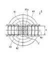
ここで本発明においては、前記投影レンズ4を光軸中心Zと焦点距離及び焦点位置が同じで外形寸法が異なる複数の投影レンズの一部を組み合わせて、光軸Z方向から見て全体を略長方形状に形成したことを特徴としており、その作成手順の一例を以下図2に沿って説明する。即ち、図2に示すように光軸中心Zと焦点距離及び焦点位置が同じで外形寸法の異なる4つの投影レンズ41、42、43、44を描き、これらの投影レンズ41、42、43、44を組み合わせて全体として略長方形状の1つの投影レンズ4を形成する例を説明する。
【0013】
まず、光軸中心Zから最も内側にある第一の投影レンズ41の上下の部分を任意の寸法hを残してP1−P2線及びP3−P4線で切除する。さらに、左右の部分は円周を残さないようにP1−P4線及びP2−P3線で切除する。こうして、光軸中心Zから最も内側にある投影レンズ41のレンズ面41aを正面(光軸Z方向)から見て、P1、P2、P3、P4で囲われた略長方形状とし、この第一の投影レンズ41を基本とする。なお、図示した例ではこのレンズ面41aの形状を面積が最大となる正方形としている。
【0014】
次に、光軸中心Zから2番目に内側にある第二の投影レンズ42を前記第一の投影レンズ41が入るようにくり貫き、第一の投影レンズ41の上下の部分の切除線P1−P2線及びP3−P4線それぞれの延長線と第二の投影レンズ42のレンズの厚みが0になる円周との交点Q1、Q2、Q3、Q4を求め、上下の部分を第一の投影レンズ41と同様に寸法hを残してQ1−Q2線及びQ3−Q4線で切除し、左右の部分は円周を残さないようにQ1−Q4線及びQ2−Q3線で切除する。
【0015】
次に、光軸中心Zから3番目に内側にある第三の投影レンズ43を前記第二の投影レンズ42が入るようにくり貫き、第二の投影レンズ42の上下の部分の切除線Q1−Q2線及びQ3−Q4線それぞれの延長線と第三の投影レンズ43のレンズの厚みが0になる円周との交点R1、R2、R3、R4を求め、上下の部分を第一の投影レンズ41及び第二の投影レンズ42と同様に寸法hを残してR1−R2線及びR3−R4線で切除し、左右の部分は円周を残さないようにR1−R4線及びR2−R3線で切除する。
【0016】
最後に、光軸中心Zから最も外側にある第四の投影レンズ44を前記第三の投影レンズ43が入るようにくり貫き、第三の投影レンズ43の上下の部分の切除線R1−R2線及びR3−R4線それぞれの延長線と第四の投影レンズ44のレンズの厚みが0になる円周との交点S1、S2、S3、S4を求め、上下の部分を第一、第二、第三の投影レンズ41、42、43と同様に寸法hを残してS1−S2線及びS3−S4線で切除し、左右の部分は円周を残さないようにS1−S4線及びS2−S3線で切除する。
【0017】
こうして、光軸中心Zと焦点距離及び焦点位置が同じで外形寸法が異なる4つの投影レンズ41、42、43、44の一部を組み合わせて光軸Z方向(正面)から見て全体が略長方形状とされた投影レンズ4が形成される。
【0018】
図3は、投影レンズ4全体を示す斜視図であり、各投影レンズ41、42、43、44のレンズ面41a、42a、43a、44aは、光軸Zと略水平な段差部42b、43b、44bで繋がっている。なお、投影レンズ4全体の厚みが0となる面は適当な厚みを持ったフランジ4cが形成されていて、このフランジ4c上に各投影レンズ41〜44が支持されている。ここで点線で示す44a’は、光軸中心Zから最も外側の投影レンズ44のみによって投影レンズ4全体を形成したと仮定した場合のレンズ面を示しており、本発明実施形態によって全体として薄型、軽量化が図れ、また、投影レンズ4を正面から見た形状も従来の円形のものと異なり、斬新なデザイン形状のものが得られ、外観の差別化が図れる。
【0019】
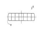
また、光軸中心Zから最も外側の投影レンズ44の左右部分はS1−S4線及びS2−S3線で切除して切除面4dを形成するものとしたが、図4に示すように切除面4dを形成せずに投影レンズ44の外形を構成する円弧形状Rをそのまま残して、図5に示すように、光軸Z方向(正面)から見て全体を略小判型のものとしても良い。
【0020】
図6は、以上のようにして形成された投影レンズ4を用いて構成されたプロジェクタ型ランプ1の配光パターンMを示すものであり、自動車用の走行用ヘッドランプとして必要とされる手前の明るさを抑えて遠方を明るく照らす横長の照射特性のものが得られる。
【0021】
なお、各投影レンズ41、42、43、44の段差部42b、43b、44bには、光源3からの光は入射しないので、その部分を着色することでヘッドランプとしての投光色に影響を与えることなく、非点灯時の見栄えをより斬新なものとすることができる。また、図7に示すように段差部42b、43b、44bを繋げた着色部材4’を投影レンズ4に被せる構造としても良い。
【0022】
また、ここまでは遠方視認性を高めるための投影レンズ4の形状について説明してきたが、左右に拡散させる光を得ることもできる。この場合には、図8乃至図9に示すように最も外側の投影レンズ44のレンズ面44aの長手方向断面の形状を光軸Zと略垂直な直線形状とするものである。これによって、図1に示す第一実施形態の投影レンズ44のレンズ面44aから出射される平行光L(図6の斜線部Nの配光)は、図9に示すL’として左右に拡散した配光を得ることもできる。
【0023】
さらに、上記実施形態では投影レンズ4を横長の長方形状として配置した例で説明してきたが、必要とされる配光パターンによっては縦長の長方形状として配置しても良く、この場合には単に同じ構成の投影レンズ4を横から縦に90°回転させて配置すれば良い。
【0024】
【発明の効果】
以上説明したように本発明によれば、回転楕円面など楕円系の2つの焦点を有する反射鏡と、該反射鏡の第一焦点近傍に配置された光源と、該光源からの光が収束する第二焦点近傍に焦点を有するように配置された投影レンズとを備えたプロジェクタ型ランプにおいて、前記投影レンズは、光軸中心と焦点距離及び焦点位置が同じで外形寸法が異なる複数の投影レンズの一部を組み合わせて光軸方向から見て全体が略長方形状に形成されており、これら複数の投影レンズ間の境界部は、光軸方向から見て各投影レンズの外形線と各投影レンズの肉厚が0になる線との交点を結んだ直線によって形成され、投影レンズの長手方向断面では各投影レンズのレンズ面が光軸と略水平な段差部によって繋がっていることを特徴とするプロジェクタ型ランプとしたことで、走行配光用のヘッドランプとして求められる手前の明るさを抑えて遠方を明るく照らす優れた照射特性のものが得られ、また、投影レンズの薄型、軽量化が図れ、投影レンズを正面から見た形状も従来の円形のものと異なり、斬新なデザイン形状のものとなって、外観の差別化が図れる優れた効果を奏するものである。
【図面の簡単な説明】
【図1】本発明に係るプロジェクタ型ランプの第一実施形態を示す断面図である。
【図2】投影レンズの作成手順を示す説明図である。
【図3】投影レンズの第一実施形態を示す斜視図である。
【図4】投影レンズの第二実施形態の要部を示す斜視図である。
【図5】投影レンズの第二実施形態を示す正面図である。
【図6】本発明に係るプロジェクタ型ランプの配光パターンを示す図である。
【図7】着色部材を示す斜視図である。
【図8】投影レンズの第三実施形態を示す斜視図である。
【図9】投影レンズの第三実施形態を示す断面図である。
【図10】従来例を示す垂直断面図である。
【符号の説明】
1……車両用灯具
2……反射鏡
3……光源
4……投影レンズ
41a,42a,43a,44a……レンズ面
42b,43b,44b……段差部
4c……フランジ
4d……切除面[0001]
BACKGROUND OF THE INVENTION
The present invention relates to a lamp such as a headlamp and a fog lamp for a vehicle, and more specifically, a reflector having two elliptical focal points such as a spheroid and a first mirror. A light source, a projection lens arranged so as to have a focal point near the second focal point where the light from the light source converges, and a light distribution characteristic arranged near the focal position of the projection lens as necessary. The present invention relates to a projector type lamp constituted by a shade.
[0002]
[Prior art]
In general, this type of projector-
[0003]
Furthermore, if a
[0004]
[Problems to be solved by the invention]
However, in such a conventional projector-
[0005]
Therefore, the light cannot be concentrated at a desired position, and it has a superior characteristic in terms of forming the shape of the light distribution characteristic, but the degree of freedom in terms of illuminance distribution within the shape of the light distribution characteristic. For example, it has been problematic in that it cannot be used as a lamp that requires illumination characteristics that illuminate a distant place by reducing the front brightness, such as a headlamp for running light distribution.
[0006]
Further, since the
[0007]
Further, since the heat from the
[0008]
In addition, in order to obtain the above-mentioned irradiation characteristics, that is, the irradiation characteristics that illuminate far away by suppressing the brightness in front and the degree of freedom in the design, the vertical end of the projection lens is cut off and viewed from the optical axis direction. A horizontally long projection lens has been proposed. However, if it is a horizontally long shape, the external dimensions of the projection lens before cutting are inevitably large, and the larger the external dimensions, the thicker the lens. However, the lens could not be reduced in weight, and the problem could not be solved.
[0009]
[Means for Solving the Problems]
In order to solve the above-described problems, the present invention employs the following means. That is, the present invention provides a reflecting mirror having two elliptical focal points such as a spheroid, a light source disposed near the first focal point of the reflecting mirror, and a second focal point where light from the light source converges. A projection lens arranged so as to have a focal point, and the projection lens is a combination of a part of a plurality of projection lenses having the same optical axis center, focal length, and focal position and different external dimensions, and a plurality of projection lenses. By cutting off a part of the outline of the circumference in the optical axis direction, the whole is formed in a substantially rectangular shape when viewed from the optical axis direction, and the boundary between the plurality of projection lenses is from the optical axis direction. As seen, each projection lens is formed by a straight line that connects the intersection of the outline after cutting of each projection lens and the circumferential line where the thickness of each projection lens before cutting is zero. The lens surface is almost horizontal to the optical axis Characterized in that connected by the difference unit.
[0010]
DETAILED DESCRIPTION OF THE INVENTION
Next, the present invention will be described in detail based on embodiments shown in the drawings.
[0011]
FIG. 1 is a cross-sectional view showing a first embodiment of a projector-type lamp 1 according to the present invention. The projector-type lamp 1 includes a reflecting
[0012]
Here, in the present invention, the projection lens 4 is combined with a part of a plurality of projection lenses having the same focal length and focal position as the optical axis center Z but having different outer dimensions, and the whole as viewed from the optical axis Z direction. An example of the creation procedure will be described below with reference to FIG. That is, as shown in FIG. 2, four
[0013]
First, the upper and lower portions of the
[0014]
Next, the
[0015]
Next, the
[0016]
Finally, the
[0017]
In this way, a part of the four
[0018]
FIG. 3 is a perspective view showing the entire projection lens 4. The lens surfaces 41 a, 42 a, 43 a, 44 a of the
[0019]
In addition, the left and right portions of the
[0020]
FIG. 6 shows a light distribution pattern M of the projector-type lamp 1 configured by using the projection lens 4 formed as described above. This is the front side required as a traveling headlamp for an automobile. It is possible to obtain a horizontally long illumination characteristic that illuminates far away with reduced brightness.
[0021]
In addition, since the light from the
[0022]
Moreover, although the shape of the projection lens 4 for improving far visibility has been described so far, it is also possible to obtain light that diffuses to the left and right. In this case, as shown in FIGS. 8 to 9, the shape of the cross section in the longitudinal direction of the
[0023]
Further, in the above embodiment, the example in which the projection lens 4 is arranged as a horizontally long rectangular shape has been described. However, depending on the required light distribution pattern, it may be arranged as a vertically long rectangular shape. What is necessary is just to arrange | position the projection lens 4 of a structure rotated 90 degrees vertically from the side.
[0024]
【The invention's effect】
As described above, according to the present invention, a reflecting mirror having two elliptical focal points such as a spheroid, a light source disposed near the first focal point of the reflecting mirror, and light from the light source converge. A projection type lamp including a projection lens arranged to have a focal point in the vicinity of the second focal point, wherein the projection lens includes a plurality of projection lenses having the same optical axis center, focal length, and focal position, and different external dimensions. The whole is formed in a substantially rectangular shape when viewed from the optical axis direction by combining a part, and the boundary between the plurality of projection lenses is the outline of each projection lens and the projection lens when viewed from the optical axis direction. Projector formed by a straight line connecting intersections with a line having a thickness of 0, and in the longitudinal section of the projection lens, the lens surface of each projection lens is connected to the optical axis by a substantially horizontal step. Type la As a result, it is possible to obtain an excellent illumination characteristic that illuminates far away by suppressing the front brightness required for headlamps for running light distribution. The shape of the lens viewed from the front is different from the conventional circular shape, and has a novel design shape, which has an excellent effect of differentiating the appearance.
[Brief description of the drawings]
FIG. 1 is a cross-sectional view showing a first embodiment of a projector-type lamp according to the present invention.
FIG. 2 is an explanatory diagram showing a procedure for creating a projection lens.
FIG. 3 is a perspective view showing a first embodiment of a projection lens.
FIG. 4 is a perspective view showing a main part of a second embodiment of the projection lens.
FIG. 5 is a front view showing a second embodiment of the projection lens.
FIG. 6 is a diagram showing a light distribution pattern of a projector type lamp according to the present invention.
FIG. 7 is a perspective view showing a coloring member.
FIG. 8 is a perspective view showing a third embodiment of the projection lens.
FIG. 9 is a cross-sectional view showing a third embodiment of the projection lens.
FIG. 10 is a vertical sectional view showing a conventional example.
[Explanation of symbols]
DESCRIPTION OF SYMBOLS 1 ...
Claims (5)
Translated fromJapanese前記投影レンズは、光軸中心と焦点距離及び焦点位置とが同じで外形寸法が異なる複数の投影レンズの一部を組み合わせかつ前記複数の投影レンズの光軸方向における円周の外形線の一部を切除することによって、光軸方向から見て全体が略長方形状に形成されており、
これら複数の投影レンズ間の境界部は、光軸方向から見て各投影レンズの切除後の外形線と切除前の各投影レンズの肉厚が0になる円周の線との交点を結んだ直線によって形成され、
投影レンズの長手方向断面では各投影レンズのレンズ面が光軸と略水平な段差部によって繋がっていることを特徴とするプロジェクタ型ランプ。A reflecting mirror having two elliptical focal points such as a spheroid, a light source arranged near the first focal point of the reflecting mirror, and a focal point located near the second focal point where the light from the light source converges In a projector-type lamp having a projected lens,
The projection lens is a combination of a part of a plurality of projection lenses having the same optical axis center, focal length, and focal position and different outer dimensions,and a partof a circumferential outline of the plurality of projection lenses in the optical axis direction. The whole is formed in a substantially rectangular shape when viewed fromthe optical axis direction,
The boundary between the plurality of projection lenses connects the intersection ofthe outlineaftercutting of each projection lens and thecircumferential line where the thicknessof each projection lensbefore cutting is zero when viewed from the optical axis direction. Formed by straight lines,
A projector-type lamp, characterized in that a lens surface of each projection lens is connected by a step portion substantially horizontal to the optical axis in a longitudinal section of the projection lens.
長手方向断面のレンズ面形状を光軸と略垂直な直線としたことを特徴とする請求項1乃至請求項3記載のプロジェクタ型ランプ。The projection lens located on the outermost side from the optical axis center of the projection lens,
4. The projector-type lamp according to claim 1, wherein the lens surface shape of the longitudinal section is a straight line substantially perpendicular to the optical axis.
Priority Applications (4)
| Application Number | Priority Date | Filing Date | Title |
|---|---|---|---|
| JP2001085090AJP3634763B2 (en) | 2001-03-23 | 2001-03-23 | Projector type lamp |
| US10/103,564US6700316B2 (en) | 2001-03-23 | 2002-03-22 | Projector type lamp |
| EP02006802AEP1243844B1 (en) | 2001-03-23 | 2002-03-25 | Projector type lamp |
| DE60236707TDE60236707D1 (en) | 2001-03-23 | 2002-03-25 | Headlamps according to the projection principle |
Applications Claiming Priority (1)
| Application Number | Priority Date | Filing Date | Title |
|---|---|---|---|
| JP2001085090AJP3634763B2 (en) | 2001-03-23 | 2001-03-23 | Projector type lamp |
Publications (2)
| Publication Number | Publication Date |
|---|---|
| JP2002289009A JP2002289009A (en) | 2002-10-04 |
| JP3634763B2true JP3634763B2 (en) | 2005-03-30 |
Family
ID=18940661
Family Applications (1)
| Application Number | Title | Priority Date | Filing Date |
|---|---|---|---|
| JP2001085090AExpired - Fee RelatedJP3634763B2 (en) | 2001-03-23 | 2001-03-23 | Projector type lamp |
Country Status (4)
| Country | Link |
|---|---|
| US (1) | US6700316B2 (en) |
| EP (1) | EP1243844B1 (en) |
| JP (1) | JP3634763B2 (en) |
| DE (1) | DE60236707D1 (en) |
Families Citing this family (16)
| Publication number | Priority date | Publication date | Assignee | Title |
|---|---|---|---|---|
| FR2837908B1 (en)* | 2002-03-28 | 2004-06-11 | Valeo Vision | LIGHTING PROJECTOR EQUIPPED WITH A SWIVEL ELLIPTICAL REFLECTOR AND A FIXED LENS FOR THE REALIZATION OF A TURNING BEAM |
| DE10361118B4 (en)* | 2003-12-22 | 2011-12-22 | Auer Lighting Gmbh | Fresnels |
| JP2006071950A (en)* | 2004-09-01 | 2006-03-16 | Canon Inc | Optical equipment |
| FR2878020B1 (en)* | 2004-11-18 | 2008-12-19 | Valeo Vision Sa | LIGHTING AND / OR SIGNALING DEVICE FOR A MOTOR VEHICLE PRODUCING A BEAM ON THE SIDE OF A MOTOR VEHICLE |
| US7563008B2 (en)* | 2006-03-28 | 2009-07-21 | Visteon Global Technologies, Inc. | LED projector headlamps using single or multi-faceted lenses |
| DE102007015012A1 (en)* | 2006-03-29 | 2008-01-24 | Stanley Electric Co. Ltd. | lighting device |
| CN101398492A (en)* | 2007-09-24 | 2009-04-01 | 深圳市九洲光电子有限公司 | Optical lens |
| JP2010048850A (en)* | 2008-08-19 | 2010-03-04 | Seiko Epson Corp | Lens array and line head |
| US9024546B2 (en)* | 2009-07-28 | 2015-05-05 | Hewlett-Packard Development Company, L.P. | Illuminated latch |
| JP5497471B2 (en)* | 2010-02-17 | 2014-05-21 | 株式会社小糸製作所 | Vehicle lighting |
| JP2013101881A (en)* | 2011-11-09 | 2013-05-23 | Stanley Electric Co Ltd | Vehicle headlamp |
| JP2014089941A (en)* | 2012-10-03 | 2014-05-15 | Koito Mfg Co Ltd | Vehicular lighting unit |
| JP6131571B2 (en)* | 2012-11-13 | 2017-05-24 | 市光工業株式会社 | Vehicle lighting |
| CN105042511B (en)* | 2015-08-14 | 2018-04-13 | 华南理工大学 | Forming method for LED motorcycle headlamp optical lens free form surface |
| KR102673141B1 (en) | 2021-06-22 | 2024-06-10 | 현대모비스 주식회사 | Lamp for vehicle and vehicle including the same |
| JP2024039527A (en)* | 2022-09-09 | 2024-03-22 | 株式会社小糸製作所 | lighting unit |
Family Cites Families (17)
| Publication number | Priority date | Publication date | Assignee | Title |
|---|---|---|---|---|
| US1955599A (en)* | 1931-07-30 | 1934-04-17 | Us Holding Corp | Motor vehicle headlight |
| US3743385A (en)* | 1970-04-02 | 1973-07-03 | Anchor Hocking Corp | Fresnel aspheric lens |
| US4198182A (en)* | 1975-09-20 | 1980-04-15 | Lucas Industries Limited | Method of manufacturing a mould for producing a lamp lens element |
| DE3226580A1 (en)* | 1981-12-08 | 1983-06-16 | Robert Bosch Gmbh, 7000 Stuttgart | HEADLIGHTS FOR MOTOR VEHICLES |
| US4904069A (en)* | 1987-12-14 | 1990-02-27 | Ichikoh Industries, Ltd. | Fresnel-type aspheric prism lens |
| JPH01225001A (en)* | 1988-03-01 | 1989-09-07 | Koito Mfg Co Ltd | Headlight for vehicle |
| NL8901077A (en)* | 1989-04-28 | 1990-11-16 | Koninkl Philips Electronics Nv | OPTICAL EXPOSURE SYSTEM AND PROJECTION DEVICE EQUIPPED WITH SUCH A SYSTEM. |
| JP2655741B2 (en)* | 1990-06-25 | 1997-09-24 | 株式会社小糸製作所 | Projection type automotive headlamp |
| US5655832A (en)* | 1992-04-16 | 1997-08-12 | Tir Technologies, Inc. | Multiple wavelength light processor |
| JP2587355Y2 (en) | 1992-12-07 | 1998-12-16 | 株式会社小糸製作所 | Condenser Fresnel lens for projector type lighting |
| JPH06331941A (en)* | 1993-05-19 | 1994-12-02 | Olympus Optical Co Ltd | Projection lens system |
| US5927848A (en)* | 1995-09-14 | 1999-07-27 | Koito Manufacturing Co., Ltd. | Vehicular lamp and lamp body therefor |
| JP3005954B2 (en)* | 1998-04-10 | 2000-02-07 | スタンレー電気株式会社 | Lamp |
| DE29813531U1 (en)* | 1998-07-30 | 1998-11-05 | Docter Optics GmbH, 07318 Saalfeld | Optical component for headlights |
| DE19856281B4 (en)* | 1998-12-07 | 2013-06-13 | Automotive Lighting Reutlingen Gmbh | Headlamp for vehicles according to the projection principle |
| JP3886672B2 (en) | 1999-07-12 | 2007-02-28 | 株式会社小糸製作所 | Vehicle headlamp |
| FR2799153A1 (en)* | 1999-09-30 | 2001-04-06 | Valeo Vision | Injection-compression molding of elliptical convergent Fresnel lens for use in vehicle headlight, uses mold with poly=optical surface |
- 2001
- 2001-03-23JPJP2001085090Apatent/JP3634763B2/ennot_activeExpired - Fee Related
- 2002
- 2002-03-22USUS10/103,564patent/US6700316B2/ennot_activeExpired - Lifetime
- 2002-03-25EPEP02006802Apatent/EP1243844B1/ennot_activeExpired - Lifetime
- 2002-03-25DEDE60236707Tpatent/DE60236707D1/ennot_activeExpired - Lifetime
Also Published As
| Publication number | Publication date |
|---|---|
| JP2002289009A (en) | 2002-10-04 |
| US6700316B2 (en) | 2004-03-02 |
| EP1243844A3 (en) | 2004-03-17 |
| EP1243844A2 (en) | 2002-09-25 |
| DE60236707D1 (en) | 2010-07-29 |
| EP1243844B1 (en) | 2010-06-16 |
| US20020135280A1 (en) | 2002-09-26 |
Similar Documents
| Publication | Publication Date | Title |
|---|---|---|
| JP3634763B2 (en) | Projector type lamp | |
| JP3005954B2 (en) | Lamp | |
| JP3005687B2 (en) | Lamp | |
| JP4548981B2 (en) | Projector type lamp | |
| JP3005955B2 (en) | Lamp | |
| JP3677720B2 (en) | Projector type headlamp | |
| JP2945376B1 (en) | Light fixture | |
| JPS6215701A (en) | Projector for passing beam or fog lamp of automobile | |
| JP2000173319A (en) | Lamp | |
| JP4009443B2 (en) | Projector type headlamp | |
| JP3958653B2 (en) | head lamp | |
| JP3996750B2 (en) | head lamp | |
| JP4062662B2 (en) | Lighting fixtures for vehicles | |
| JP3562687B2 (en) | Projector type lamp | |
| JPH0337242B2 (en) | ||
| JPH10261302A (en) | Projector type lamp | |
| JP4062643B2 (en) | Lamp | |
| JPS6348014Y2 (en) | ||
| JP2000299005A (en) | Vehicle lighting fixtures | |
| JPH04223001A (en) | compound reflector | |
| JPH065101A (en) | Head lamp for automobile | |
| JP2001266614A (en) | Signal lights for vehicles | |
| JPH0319121Y2 (en) | ||
| JPH11329004A (en) | Lamp | |
| JPH0418402B2 (en) |
Legal Events
| Date | Code | Title | Description |
|---|---|---|---|
| A977 | Report on retrieval | Free format text:JAPANESE INTERMEDIATE CODE: A971007 Effective date:20040809 | |
| A131 | Notification of reasons for refusal | Free format text:JAPANESE INTERMEDIATE CODE: A131 Effective date:20040831 | |
| A521 | Request for written amendment filed | Free format text:JAPANESE INTERMEDIATE CODE: A523 Effective date:20041026 | |
| TRDD | Decision of grant or rejection written | ||
| A01 | Written decision to grant a patent or to grant a registration (utility model) | Free format text:JAPANESE INTERMEDIATE CODE: A01 Effective date:20041214 | |
| A61 | First payment of annual fees (during grant procedure) | Free format text:JAPANESE INTERMEDIATE CODE: A61 Effective date:20041224 | |
| R150 | Certificate of patent or registration of utility model | Free format text:JAPANESE INTERMEDIATE CODE: R150 | |
| FPAY | Renewal fee payment (event date is renewal date of database) | Free format text:PAYMENT UNTIL: 20080107 Year of fee payment:3 | |
| FPAY | Renewal fee payment (event date is renewal date of database) | Free format text:PAYMENT UNTIL: 20100107 Year of fee payment:5 | |
| FPAY | Renewal fee payment (event date is renewal date of database) | Free format text:PAYMENT UNTIL: 20110107 Year of fee payment:6 | |
| FPAY | Renewal fee payment (event date is renewal date of database) | Free format text:PAYMENT UNTIL: 20120107 Year of fee payment:7 | |
| FPAY | Renewal fee payment (event date is renewal date of database) | Free format text:PAYMENT UNTIL: 20120107 Year of fee payment:7 | |
| FPAY | Renewal fee payment (event date is renewal date of database) | Free format text:PAYMENT UNTIL: 20130107 Year of fee payment:8 | |
| FPAY | Renewal fee payment (event date is renewal date of database) | Free format text:PAYMENT UNTIL: 20130107 Year of fee payment:8 | |
| FPAY | Renewal fee payment (event date is renewal date of database) | Free format text:PAYMENT UNTIL: 20140107 Year of fee payment:9 | |
| R250 | Receipt of annual fees | Free format text:JAPANESE INTERMEDIATE CODE: R250 | |
| R250 | Receipt of annual fees | Free format text:JAPANESE INTERMEDIATE CODE: R250 | |
| LAPS | Cancellation because of no payment of annual fees |