JP3634614B2 - Communication system and communication apparatus - Google Patents
Communication system and communication apparatusDownload PDFInfo
- Publication number
- JP3634614B2 JP3634614B2JP3451998AJP3451998AJP3634614B2JP 3634614 B2JP3634614 B2JP 3634614B2JP 3451998 AJP3451998 AJP 3451998AJP 3451998 AJP3451998 AJP 3451998AJP 3634614 B2JP3634614 B2JP 3634614B2
- Authority
- JP
- Japan
- Prior art keywords
- icon
- state
- information
- control unit
- drawing control
- Prior art date
- Legal status (The legal status is an assumption and is not a legal conclusion. Google has not performed a legal analysis and makes no representation as to the accuracy of the status listed.)
- Expired - Fee Related
Links
Images


Classifications
- G—PHYSICS
- G06—COMPUTING OR CALCULATING; COUNTING
- G06F—ELECTRIC DIGITAL DATA PROCESSING
- G06F3/00—Input arrangements for transferring data to be processed into a form capable of being handled by the computer; Output arrangements for transferring data from processing unit to output unit, e.g. interface arrangements
- G06F3/01—Input arrangements or combined input and output arrangements for interaction between user and computer
- G06F3/048—Interaction techniques based on graphical user interfaces [GUI]
- G06F3/0481—Interaction techniques based on graphical user interfaces [GUI] based on specific properties of the displayed interaction object or a metaphor-based environment, e.g. interaction with desktop elements like windows or icons, or assisted by a cursor's changing behaviour or appearance
- G06F3/04817—Interaction techniques based on graphical user interfaces [GUI] based on specific properties of the displayed interaction object or a metaphor-based environment, e.g. interaction with desktop elements like windows or icons, or assisted by a cursor's changing behaviour or appearance using icons
Landscapes
- Engineering & Computer Science (AREA)
- General Engineering & Computer Science (AREA)
- Theoretical Computer Science (AREA)
- Human Computer Interaction (AREA)
- Physics & Mathematics (AREA)
- General Physics & Mathematics (AREA)
- Computer And Data Communications (AREA)
- User Interface Of Digital Computer (AREA)
Description
Translated fromJapanese【0001】
【発明の属する技術分野】
本発明は、ネットワーク上の状態が動的に変化する資源に対しアクセスする通信システムと、その通信システムに組み込まれ、動的に変化する状態情報を受信する通信装置に関する。
【0002】
【従来の技術】
ネットワーク環境の発展とともに、状態が動的に変更する資源、例えばユーザの計算機の使用状況を示す情報をネットワークを通して共有する必要が、とりわけモバイル・コンピューティングの一般化とともに増大している。
これに対し、従来は、状態が動的に変更する資源、例えば登録されたホストの利用状況や、株価などを監視し、一定の時間間隔または状態の変更時に、特定のクライアント上で動くアプリケーションにネットワークを介して状態を送信して、表示を行なうシステムが実現されている。
【0003】
また、ネットワークに存在するオブジェクトを、例えばそのアドレスを指すアイコンで表現し、そのアイコンと、他アイコンやウインドウなどのデスクトップオブジェクトとの重ね合わせにより、それぞれの組み合わせに対応する処理(アクション)が行なわれる方式が実現されている。そうしたオブジェクトを、ネットワークで配布可能な文書に張り付けたり、ウインドウシステムのデスクトップや他ウインドウへのドラッグ&ドロップ操作などにより、他アプリケーションで利用することも可能である。
【0004】
【発明が解決しようとする課題】
ネットワーク上の、状態が動的に変化する資源からの情報の利用は、特定のアプリケーションに依存しているため、他のアプリケーションで利用するには複雑な操作を行なう必要がある。また、ネットワークに存在する資源を指すオブジェクトを表すアイコンを扱えるウインドウシステムにおいては、その資源の状態を動的に反映する機能は実現されていない。
【0005】
本発明は、上記事情に鑑み、動的に変化した状態の把握が容易な通信システムおよび通信装置を提供することを目的とする。
【0006】
【課題を解決するための手段】
上記目的を達成する本発明の通信システムは、
(1)変更可能な状態情報を保持する状態保持部と、状態情報の通知先アドレスを保持し、その通知先アドレスに向けて前記状態保持部が保持する状態情報を送信する状態通知部とを備えた第1の通信装置、および
(2)複数の異なるアプリケーション間で複製が可能なアイコンであってアプリケーション上の1つもしくは複製により数が増えた複数のアイコンの描画を担う描画制御部と、上記第1の通信装置が送信した状態情報を受信して、描画制御部に、その描画制御部が描く1つもしくは複数のアイコン上に、受信した状態情報があらわす状態を反映させるよう指示するアイコン管理部とを備えた、ネットワークを介して第1の通信装置に接続された第2の通信装置とを有することを特徴とする。
【0007】
本発明の通信システムは、表示されるアイコン自体が状態を反映したアイコンであり、このため、状態や状態の変化を容易に把握することができる。また、上記描画制御部は、異なるアプリケーション間でアイコンが複製された場合には、それら複数のアイコンに対し状態を反映させるものであるため、アイコンを自由に複製し、複製により数が増えたアイコンのうちのどのアイコンからも状態やその状態の変化を容易に把握することができる。
【0008】
ここで、上記本発明の通信システムにおいて、上記アイコン管理部が、上記第1の通信装置に対し、状態情報の送信の頻度を指定する手段を有し、
上記状態通知部が、通知先アドレスに対応して状態情報の送信の頻度情報を保持し、その通知先アドレスに向けて、その通知先アドレスに対応して保持された頻度情報に応じた頻度で状態情報を送信するものであることが好ましい。
【0009】
このように構成することにより、第2の通信装置側で、上記の状態表示アイコンが存在するアプリケーションの種類やアプリケーションからの指示に応じて頻度を指定し、そのアプリケーション等に適切な頻度で状態情報が送られることになり、ネットワーク負荷を低減することができる。
また、上記本発明の通信システムにおいて、上記状態通知部が、通知先アドレスに対応して送信可能な状態情報と送信が禁止された状態情報との識別情報を保持し、その通知先アドレスに向けて、その通知先アドレスに対応して保持された識別情報に応じた送信可能な状態情報を送信するものであることが好ましい。
【0010】
例えば、この通信システムを含むネットワークがある会社の社内に広がるとともに、さらに社外にまで広がっているような状況において、上記のように構成することにより、社内の人に配信する状態情報と社外の人に配信する状態情報を異ならせることができる。識別情報は状態情報の受信先に応じてあらかじめ定められたものであってもよいが、状態情報の受信側からのパスワードを受け取ってその識別情報を変更するものであってもよい。
【0011】
さらに、上記本発明の通信システムにおいて、上記状態保持部が、その状態保持部が保持する状態情報を、ネットワークを経由して送られてきた情報に基づいて変更するものであることも好ましい形態である。
このように構成することで、例えば上記第1の通信装置がサーバ、第2の通信装置(複数)がクライアントであるサーバ・クライアントシステムにおいて、あるクライアントの動的状態をネットワークを介してサーバに送り、サーバが他のクライアントにその送られてきた動的状態を配信し、クライアントどうしが互いの状態をアイコンで知ることができるようになる。
【0012】
また、上記目的を達成する本発明の通信装置は、上記通信システムを構成する第2の通信装置として使用可能なものであり、ネットワークに接続された通信装置であって、複数の異なるアプリケーション間で複製が可能なアイコンであってアプリケーション上の1つもしくは複製により数が増えた複数のアイコンの描画を担う描画制御部と、ネットワークを経由して送信されてきた、逐次変更され得る状態情報を受信して、描画制御部に、その描画制御部が描く1つもしくは複数のアイコン上に、受信した状態情報があらわす状態を反映させるよう指示するアイコン管理部とを備えたことを特徴とする。
【0013】
ここで、上記本発明の通信装置において、上記描画制御部は、同一の状態情報があらわす状態を異なる態様で反映させる複数種類のアイコンが存在する場合に、当該アイコンそれぞれを用意させるものであって、
上記アイコン管理部が、アイコンの描画を担当させる描画制御部を選択し選択した描画制御部にアイコンの描画を担当させるものであることが好ましい態様の1つである。
【0014】
この態様によれば、アプリケーションの種類やアプリケーションからの指示等に応じて異なる描画制御部にアイコンの描画を担当させ、アプリケーション等に応じた好適な形式での情報表示が可能となる。
また、上記本発明の通信装置において、上記アイコン管理部が、指示に応じて、上記描画制御部に、指示に応じたアイコンを消去させるものであることが好ましい。
【0015】
不要になったアイコンを削除することにより、その通信装置の負荷やネットワークの負荷を低減することができる。
また、上記本発明の通信装置において、上記アイコン管理部が、描画制御部により描画されたアイコンと他のオブジェクトとが結合されたことをあらわす情報を受け取って、結合された他のオブジェクトと連携するとともにその結合されたアイコンに反映された状態に応じた動作を実行するものであることも好ましい態様である。
【0016】
この態様によれば、例えばアイコンのドラッグアンドドロップ操作等の直感的な操作で、そのアイコンの動的状態を反映した処理が実行される。
さらに、上記本発明の通信装置において、上記描画制御部は、アプリケーション毎に用意され、そのアプリケーション上のアイコンの描画を担うものであって、
上記アイコン管理部が、受信した状態情報を、1つもしくは複数のアプリケーション上の、1つもしくは複製により数が増えた複数のアイコンそれぞれを描画する描画制御部に配信するものであることが好ましい。
【0017】
この場合、ネットワークを介しての通信はひとつのアイコン管理部が行ない、そのアイコン管理部が必要な情報を1つもしくは複数の描画制御部に配信することで、ネットワークの負荷や情報送信側の負荷を低く抑えることができる。
【0018】
【発明の実施の形態】
以下、本発明の実施形態について説明する。
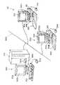
図1は、本発明の通信システムの一構成例を示す模式図である。
ここには、例示的に2台のクライアント100,200と、1台のサーバ300が示されており、これらクライアント100,200とサーバ300は、ネットワーク600を介して相互に接続されている。
【0019】
各クライアント100,200、サーバ300は、それぞれがコンピュータシステムで構成されており、各クライアント100,200は、本発明の通信システムにおける第2の通信装置、サーバ300は本発明の通信システムにおける第1の通信装置に相当し、さらに各クライアント100,200は、それぞれが本発明の通信装置にも相当する。
【0020】
各クライアント100,200およびサーバ300は、CPU、主記憶装置、ハードディスク、通信用ボード等が内蔵された本体部101,201,301、本体部101,201,301からの指示により表示画面102a,202a,302a上に画像を表示する画像表示部102,202,302、コンピュータ100,200,300にオペレータの指示を入力するためのキーボード103,203,303、表示画面102a,202a,302a上の任意の位置を指定することにより、そのときにその位置に表示されていたアイコン等に応じた指示を入力するマウス104,204,304を備えている。
【0021】
本体部101,201,301には、さらに外観上、フロッピー(登録商標)ディスク、CDROM(図示せず)が装填される装填口101a,101b;201a,201b;301a,301bを有しており、その内部には、その装填口101a,101b;201a,201b;301a,301bから装填されたフロッピー(登録商標)やCDROMをドライブする、フロッピー(登録商標)ドライブ装置、CDROMドライブ装置も内蔵されている。
【0022】
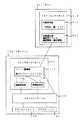
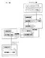
図2は、本発明の通信システムの一構成例を示した機能構成図である。ここでは、図1に示すサーバ300とクライアント100との間で通信を行なうものとして説明する。尚、図1に示すクライアント200もクライアント100と同じ構成を有するものとする。
サーバ300には、マスターコンポーネント310が備えられており、このマスターコンポーネント310は、状態保持部311と状態通知部312を有している。
【0023】
状態保持部311は、変更可能な状態情報を保持しており、この状態情報は、ここに示す例では、状態名と状態の値とのペアから成り、この値が変更されることにより状態が変化したものとなる。例えばある株価表示システムにおいて、状態名はある会社の名称であり、値は、その会社の現在の株価に相当する。
状態保持部311には、このような状態名と値とのペアからなる多数の状態情報がリスト形式で保持されている。
【0024】
また、サーバ300のマスターコンポーネント310に備えられた状態通知部312は、状態情報の通知先アドレスと、その通知先アドレスに対応して保持された頻度情報と、さらにその通知先アドレスに対応して保持された識別情報との組を、リスト形式で保存しており、その状態通知部312は、そこにリストアップされた通知先アドレスに向けて、状態保持部311に保持された状態情報を送信する。このとき、通知先アドレスに対応して頻度情報が保持されているときは、その通知先アドレスには、その頻度情報があらわす頻度で状態情報を送信する。また、識別情報は、その通知先アドレスに向けて送信してもよい状態情報とその通知先アドレスに向けては送信が禁止されている状態情報とを識別する情報であって、状態通知部312には、通知先アドレスに向けて状態情報を送信するにあたっては、その通知先アドレスに対応する識別情報を参照し、その識別情報により許可されている状態情報のみ、その通知先アドレスに向けて送信する。
【0025】
また、クライアント100には、スレイヴコンポーネント110と、ウインドウマネージャ120と、複製(ここでは代表的に2つのみ示してある)のアプリケーション130,140が備えられている。
スレイヴコンポーネント110は、アイコン管理部111と、描画制御部112A,112Bを有する。ここでは描画制御部はアイコンごとに備えられており、アイコンが複製されたときは、描画制御部も複製され、あるいはその複製されたアイコン用に他の描画制御部が起動される。この図2には、描画制御部は代表的に2つ示されている。
【0026】
描画制御部112A,112Bは、基本的には、アイコンの描画を担っており、アイコン管理部111は、基本的には、サーバ300が送信した状態情報を受信して、描画制御部112A,112Bに、その描画制御部112A,112Bが描くアイコン上に、受信した状態情報があらわす状態を反映させるよう指示する。すると描画制御部112A,112Bは、その指示に応じて、自分が担当するアイコンにその状態を反映させる。
【0027】
また、ウインドウマネージャ120は、スレイヴコンポーネント110とアプリケーション130,140との仲立ちをしながらウインドウの表示制御を担う部分である。
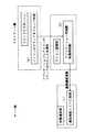
図3は、図2に示す通信システムにおけるアイコン表示の処理手順を示す図である。
【0028】
まずアプリケーションがアイコン表示命令をウインドウマネージャに出す(ステップ(a))(例えばWWWプラウザの場合は、HTML中のオブジェクトを指定するスクリプトを読み込むと、表示命令をウインドウマネージャに出す。)
すると、ウインドウマネージャは対応するアイコン管理部を起動する。
このアイコン管理部の起動にあたっては、ウインドウマネージャは、このクライアントがスレイヴコンポーネントをローカルに(すなわちこのクライアント内に)保有しているか否か判定し(ステップ(b))、もし保有していなければウインドウマネージャは指定されたアドレスからそのスレイヴコンポーネントをダウンロードする(ステップ(c))。
【0029】
次いでウインドウマネージャは、アイコン管理部が起動されているか否か判定し(ステップ(d))、起動されていなければアイコン管理部を起動する(ステップ(e))。この起動されたアイコン管理部は、サーバ側の状態通知部に対しクライアントアドレスを通知し、状態通知部では、その通知されたクライアントアドレスを通知先アドレスとしてリストに登録する(ステップ(f))。
【0030】
次いで、アイコン管理部は、そのアプリケーションに対応した描画制御部を起動し、その描画制御部は状態通知部に対し通信頻度を通知する(ステップ(g))。
状態通知部は、その通知された通信頻度をクライアントアドレスに対応づけてリストに登録する(ステップ(h))。
【0031】
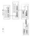
図4は、図2に示す通信システムにおけるアイコン複製の処理手順を示す図である。
ウインドウマネージャは、あるアプリケーション上のアイコンが別のアプリケーション上にドラッグアンドドロップ処理(図1に示すクライアント100のマウス104でアイコンをピッキングして、マウスボタンを押したままマウスを移動させ(すなわちピッキングしたマイコンを移動させ)、所望の位置までアイコンを移動させた後マウスボタンを離す操作)を検知することにより、そのアイコンを複製する(ステップ(a))。そのアイコンを複製したという情報はアイコン管理部に通知され、アイコン管理部はその通知を受けて、そのアイコンが複製された側のアプリケーションに応じた描画制御部を起動する(ステップ(b))。この起動された描画制御部は、サーバ側の状態通知部に対し、そのアプリケーションが、そのクライアントに対応づけられて状態通知部に現在登録されている通信頻度よりも高い通信頻度で状態情報の送信を要求する場合、その通信頻度を通知する。
【0032】
サーバ側の状態通知部は、そのクライアントから通知を受けた通信頻度を、そのクライアントのアドレスに対応づけて登録する(ステップ(a))。
以上の、図2〜図4を参照して説明した構成により、ネットワーク上の、状態が動的に変化する資源の情報を、複製可能なアイコンで表現することが可能になり、操作性の向上と情報の流通の促進が図られる。
【0033】
図5は、アプリケーションから、アイコンの表示形式や通信頻度を指定するときの処理手順を示す図である。
アプリケーションは、例えば自分が動いているコンピュータの種類を認識しそのコンピュータの性能に応じたアイコン表示を行なうべく、アイコンの表示形式や状態情報の通信頻度を指定する(ステップ(a))。
【0034】
ウインドウマネージャは、その指定を受けて、アイコン管理部に対し、その表示形式のアイコンの描画を担当する描画制御部を指定し、あるいは通信頻度を指定する(ステップ(b))。
アイコン管理部は、ウインドウマネージャから指定された描画制御部を起動し、その起動された描画制御部は、ウインドウマネージャにより指定された通信頻度が、このクライアントに対するこれまでの通信頻度よりも高い通信頻度であったとき、および他に状態情報を表示するアイコンがそのアプリケーション以外に存在していないときには、通信頻度をサーバ側に通知する(ステップ(c))。
【0035】
サーバ側の状態通知部はクライアントから通知を受けた通信頻度をそのクライアントのアドレスに対応づけて登録する(ステップ(d))。
図3,図4に示すように、ウインドウマネージャは、アイコン表示命令を出したアプリケーションの種類に応じて、異なった描画制御部を起動させることで、情報の表示形式を変化させることが可能である(例えば、デスクトップの高性能コンピュータ用のアプリケーションでは、フルアニメーションのアイコンを表示し、モバイル端末用のアプリケーションでは、たまに表示が更新されるだけのアイコンを表示するなど)。また、図5に示すように、アプリケーションからの指示により情報の表示形式を変えることもできる(アプリケーションが自分が動いているコンピュータの種類を認識し、そのコンピュータの性能に応じた表示を行うなど)。これにより、アプリケーションに応じた最適な形式での情報の表示が可能になる。
【0036】
また、図3,図4に示すように、アプリケーションの種類に応じて、アイコン管理部が通信頻度をサーバ側の状態通知部に通知することによって、サーバとクライアントの間の通信量を変化させることが可能となる。また、図5に示すように、アプリケーションからの指示により通信量を変更することもできる(アプリケーションが自分が動いているコンピュータの種類や環境を認識し、携帯電話やPHSでネットワークに接続している場合は通信量を減らすなど)。このようにして、リアルタイムでの情報の更新が要求されるアプリケーションとその必要のないアプリケーションとで通信量を変化させることで、ネットワーク負荷を減らすことができる。
【0037】
図6は、アイコン削除処理の手順を示す図である。
先ず、アプリケーションがアイコン削除命令を発すると(ステップ(a))、ウインドウマネージャは、そのアイコン削除命令をアイコン管理部へ通知する(ステップ(b))。
アイコン管理部では、そのアイコン削除命令を発したアプリケーションのアイコンの描画を担当していた描画制御部の動作を終了させる終了処理を行ない、そのアイコンを削除することに伴って通信頻度を変更する必要があるときは、サーバ側の状態通知部に通信頻度を通知し、状態通知部ではそのクライアントへの通信頻度を更新する(ステップ(c)(d))。
【0038】
アイコン管理部では、さらに、このクライアント中に状態情報を反映させるべきアイコン表示を行なう必要のあるアプリケーションがまだ残っているか否か判定し(ステップ(e))、まだ残っているときはその残っているアイコン向けの処理を続行し、残っていないときは、サーバ側の状態通知部に対し、状態情報を反映させるべきアイコンの表示が全て終了した旨、終了通知を出す(ステップ(f))。
【0039】
サーバ側の状態通知部では、その終了通知を受けて通知先アドレスリストからそのクライアントのアドレスを削除する(ステップ(h))。
また、クライアント側のアイコン管理部では、そのアイコン管理部自身の終了処理を行なう(ステップ(g))。
この図6に示すような手順により、アイコンの削除に伴い、サーバ側からの状態通知の通信を打ち切ったり通信量を減らすことができる。
【0040】
図7は、アイコンとデスクトップオブジェクトとの重ね合わせによるアクションメソッドの起動手順を示す図である。
ウインドウマネージャは、アイコンのドラッグアンドドロップ処理が行なわれたことを検知し(ステップ(a))、そのアイコンのドロップ先がデスクトップオブジェクトの画面と重なっていたときはその重なりを検知して、重なったオブジェクトの種類をアイコン管理部に通知する(ステップ(b))。
【0041】
アイコン管理部はそのドラッグアンドドロップ処理の行なわれたアイコンに対応づけられた状態に応じるとともに、その重なったオブジェクトの種類に応じたアクションメソッドを起動し(ステップ(c))、また、デスクトップオブジェクト側でもその対応づけられたアクションメソッドを起動する(ステップ(d))。
【0042】
例えば、ある人の連絡先の電話番号を示す状態表示アイコン(その人の移動に伴って連絡先の電話番号が変化するものとする)を、電話をかけるという動作を行なう電話アプリケーションアイコンに重ねることで、アイコン管理部側では、その状態表示アイコンに対応づけられているその人の現在の連絡先の電話番号を通知するというメソッドが起動されてその電話番号が電話アプリケーションに通知され、電話アプリケーションではその通知された電話番号に電話をかけるという動作が行なわれる。
【0043】
このように、アイコンとデスクトップオブジェクトとの重ねあわせを検知し、アイコン管理部とデスクトップオブジェクトがそれぞれ対応づけられた処理を行うことで、アイコンの動的状態を反映した処理を、ドラッグアンドドロップという直感的な操作で行うことが可能になる。
図8は、サーバ側にある状態情報のアクセスを制御するアクセス制御機構の一例を示す図である。
【0044】
ウインドウマネージャにより、認証情報(パスワード)入力用のウインドウを開くアイコンがクリックされたことが検出されると(ステップ(a))、そのアイコンに対応する描画制御部は、認証情報入力ウインドウを起動し(ステップ(b))、そのウインドウに認証情報(パスワード)が入力されると(ステップ(c))、アイコン管理部はその認証情報とクライアントアドレスをサーバ側に送信する(ステップ(d))。
【0045】
すると、サーバ側の状態保持部では認証情報が正しいか否か認識され、正しい認証情報であったときは、状態通知部に、そのクライアントアドレスが通知される(ステップ(e))。その通知を受けた状態通知部は、そのクライアントアドレスに対応づけられた、そのクライアントに向けて送信が許可された状態情報と送信が禁止された状態情報とを識別する識別情報が、それまでそのクライアントに向けての送信が禁止されていた状態情報の送信が解除されるように変更される(ステップ(f))。
【0046】
このような構成により、クライアントに応じて公開する状態、非公開の状態を定めることができる。例えば、社内の人間のみに公開する情報と、誰にでも公開する情報といった項目を定めることができる。
図9は、ネットワークを介在させた状態設定の仕組みを示した図である。
図9に示すように、クライアントが、ネットワークを介してサーバの状態保持部をアクセスしてその状態保持部に保存された状態情報を変更する状態設定部を備えることで、そのクライアントの状態ないしその状態の変化を、他のクライアントが自分のクライアント上の状態表示アイコンで監視することができる。
【0047】
図10は、描画制御部への状態情報の配信機構を示す図である。
ここには、ある1つのクライアントにおいて、サーバ側から状態情報の通知を受けるアイコン管理部は1つのみ備えられており、そのアイコン管理部は受信した状態情報を複数の描画制御部に配信する。例えば1つのクライアント上でのWWWブラウザとデスクトップとの双方で同一オブジェクトのアイコンが表示されている場合、サーバ側との通信を行なうアイコン管理部は1つでよく、そのアイコン管理部がWWWブラウザ上のアイコンを描画する描画制御部とデスクトップ上のアイコンを描画する描画制御部との双方に状態を通知する。
【0048】
この構成をとることにより、描画制御部のみでなく、アイコン管理部をも各アイコンに対応づけて備えた場合と比べ、ネットワーク上の通信量と、クライアント、サーバ双方における処理量を低く抑えることが可能となる。
【0049】
【発明の効果】
以上説明したように、本発明によれば、ネットワーク上の資源からのリアルタイム情報がアイコンに反映され、そのアイコンが複製されることで、複数のアプリケーションでその状態情報を反映したアイコンを簡便に利用することができる。
【図面の簡単な説明】
【図1】本発明の通信システムの一構成例を示す模式図である。
【図2】本発明の通信システムの一構成例を示した機能構成図である。
【図3】図2に示す通信システムにおけるアイコン表示の処理手順を示す図である。
【図4】図2に示す通信システムにおけるアイコン複製の処理手順を示す図である。
【図5】アプリケーションから、アイコンの表示形式や通信頻度を指定するときの処理手順を示す図である。
【図6】アイコン削除処理の手順を示す図である。
【図7】アイコンとデスクトップオブジェクトとの重ね合わせによるアクションメソッドの起動手順を示す図である。
【図8】サーバ側にある状態情報のアクセスを制御するアクセス制御機構の一例を示す図である。
【図9】ネットワークを介在させた状態設定の仕組みを示した図である。
【図10】描画制御部への状態情報の配信機構を示す図である。
【符号の説明】
100,200 クライアント
101,201 本体部
101a,201a 装填口
102,202 画像表示部
102a,202a 表示画面
103 キーボード
104 マウス
110 スレイブコンポーネント
111 アイコン管理部
112A,112B 描画制御部
120 ウインドウマネージャ
130,140 アプリケーション
300 サーバ
301 本体部
301a,301b 装填口
302 画像表示部
302a 表示画面
303 キーボード
304 マウス
310 マスターコンポーネント
311 状態保持部
312 状態通知部[0001]
BACKGROUND OF THE INVENTION
The present invention relates to a communication system that accesses resources whose state on a network changes dynamically, and a communication device that is incorporated in the communication system and receives state information that changes dynamically.
[0002]
[Prior art]
With the development of the network environment, the need to share resources that dynamically change the state, for example, information indicating the usage status of a user's computer, is increasing with the generalization of mobile computing.
In contrast, in the past, resources whose status changes dynamically, such as the usage status of registered hosts and stock pricesSuch There is realized a system that monitors and displays the status by transmitting the status to an application running on a specific client via a network when a certain time interval or status is changed.
[0003]
In addition, an object existing in the network is expressed by an icon indicating the address, for example, and a process (action) corresponding to each combination is performed by superimposing the icon and a desktop object such as another icon or window. The method is realized. Such objects can be used in other applications by pasting them on documents that can be distributed over a network, or by dragging and dropping them onto the desktop of a window system or other windows.
[0004]
[Problems to be solved by the invention]
The use of information from resources whose state changes dynamically on the network depends on a specific application, and therefore it is necessary to perform a complicated operation in order to use it in other applications. Further, in a window system that can handle an icon representing an object indicating a resource existing in the network, a function that dynamically reflects the state of the resource is not realized.
[0005]
In view of the above circumstances, an object of the present invention is to provide a communication system and a communication apparatus that can easily grasp a dynamically changed state.
[0006]
[Means for Solving the Problems]
A communication system of the present invention that achieves the above object is as follows.
(1) a state holding unit that holds state information that can be changed, and a state notification unit that holds a notification destination address of the state information and transmits the state information held by the state holding unit toward the notification destination address A first communication device comprising:
(2) A drawing control unit responsible for drawing one icon on an application or a plurality of icons increased in number by copying, which can be copied between a plurality of different applications, and transmitted by the first communication device An icon management unit that receives state information and instructs the drawing control unit to reflect the state represented by the received state information on one or more icons drawn by the drawing control unit; And a second communication device connected to the first communication device.
[0007]
In the communication system of the present invention, the displayed icon itself is an icon reflecting the state, and therefore, it is possible to easily grasp the change in the state and the state. In addition, when the icons are duplicated between different applications, the drawing control unit reflects the state on the plurality of icons, so the icons can be freely duplicated and the number of icons increased by duplication. It is possible to easily grasp the state and the change of the state from any of the icons.
[0008]
Here, in the communication system of the present invention, the icon management unit has means for designating the frequency of transmission of state information to the first communication device,
The status notification unit holds the frequency information of the status information corresponding to the notification destination address, and the frequency according to the frequency information held corresponding to the notification destination address toward the notification destination address. It is preferable that the status information is transmitted.
[0009]
With this configuration, the second communication device specifies the frequency according to the type of application in which the status display icon is present or an instruction from the application, and the status information is appropriate for the application. Is sent, and the network load can be reduced.
In the communication system of the present invention, the state notification unit holds identification information between state information that can be transmitted corresponding to the notification destination address and state information that is prohibited from being transmitted, and is directed to the notification destination address. Thus, it is preferable to transmit state information that can be transmitted according to the identification information held corresponding to the notification destination address.
[0010]
For example, in a situation where the network including this communication system extends to the inside of a company and further to the outside, by configuring as described above, status information distributed to people inside the company and people outside the company The status information delivered to can be made different. The identification information may be predetermined according to the reception destination of the state information, but may be one that receives the password from the reception side of the state information and changes the identification information.
[0011]
Further, in the communication system of the present invention, it is preferable that the state holding unit changes the state information held by the state holding unit based on information sent via the network. is there.
With this configuration, for example, in a server / client system in which the first communication device is a server and the second communication device (s) are clients, the dynamic state of a client is sent to the server via the network. The server distributes the sent dynamic state to other clients, and the clients can know each other's state by an icon.
[0012]
The communication device of the present invention that achieves the above object is a communication device that can be used as a second communication device constituting the communication system, and is a communication device connected to a network between a plurality of different applications. Receiving status information that can be changed sequentially, and a drawing control unit that is responsible for drawing one or more icons on the application that have been duplicated and that have increased in number due to duplication. The drawing control unit includes an icon management unit that instructs to reflect the state represented by the received state information on one or a plurality of icons drawn by the drawing control unit.
[0013]
Here, in the communication apparatus according to the present invention, the drawing control unit may include a plurality of types of icons that reflect the state represented by the same state information in different modesIf the icon exists, EachPrepare And
In one preferred embodiment, the icon management unit selects a drawing control unit responsible for drawing an icon and causes the selected drawing control unit to take charge of icon drawing.
[0014]
According to this aspect, it is possible to cause different drawing control units to draw icons according to the type of application, instructions from the application, etc., and display information in a suitable format according to the application.
In the communication device of the present invention, it is preferable that the icon management unit causes the drawing control unit to delete an icon corresponding to the instruction in response to the instruction.
[0015]
By deleting unnecessary icons, the load on the communication device and the load on the network can be reduced.
In the communication device of the present invention, the icon management unit receives information indicating that the icon drawn by the drawing control unit and another object are combined, and cooperates with the combined other object. In addition, it is also a preferable aspect that the operation corresponding to the state reflected in the combined icon is executed.
[0016]
According to this aspect, for example, the process reflecting the dynamic state of the icon is executed by an intuitive operation such as an icon drag-and-drop operation.
Further, in the communication device of the present invention, the drawing control unitIs ,applicationPrepared for each It is responsible for drawing icons on the applicationUmbrella Because
It is preferable that the icon management unit distributes the received state information to a drawing control unit that draws one or a plurality of icons increased in number by copying on one or a plurality of applications.
[0017]
In this case, communication via the network is performed by one icon management unit, and the icon management unit distributes necessary information to one or a plurality of drawing control units, so that the load on the network and the load on the information transmission side Can be kept low.
[0018]
DETAILED DESCRIPTION OF THE INVENTION
Hereinafter, embodiments of the present invention will be described.
FIG. 1 is a schematic diagram showing a configuration example of a communication system according to the present invention.
Here, two
[0019]
Each of the
[0020]
Each of the
[0021]
The
[0022]
FIG. 2 is a functional configuration diagram showing a configuration example of the communication system of the present invention. Here, description will be made assuming that communication is performed between
The
[0023]
The state holding unit 311 holds state information that can be changed. In the example shown here, the state information includes a pair of a state name and a state value, and the state is changed by changing this value. It will be changed. For example, in a stock price display system, the state name is the name of a company, and the value corresponds to the current stock price of the company.
The state holding unit 311 holds a large number of state information made up of such state name / value pairs in a list format.
[0024]
In addition, a status notification unit provided in the master component 310 of the
[0025]
The
[0026]
The
[0027]
The
FIG. 3 is a diagram showing an icon display processing procedure in the communication system shown in FIG.
[0028]
First, the application issues an icon display command to the window manager (step (a)) (for example, in the case of a WWW browser, when a script designating an object in HTML is read, a display command is issued to the window manager).
The window manager then activates the corresponding icon manager.
When the icon manager is activated, the window manager determines whether or not the client has the slave component locally (that is, in the client) (step (b)). The manager downloads the slave component from the specified address (step (c)).
[0029]
Next, the window manager determines whether or not the icon management unit is activated (step (d)), and if not activated, activates the icon management unit (step (e)). The activated icon management unit notifies the server side status notification unit of the client address, and the status notification unit registers the notified client address in the list as a notification destination address (step (f)).
[0030]
Next, the icon management unit activates a drawing control unit corresponding to the application, and the drawing control unit notifies the state notification unit of the communication frequency (step (g)).
The state notification unit registers the notified communication frequency in the list in association with the client address (step (h)).
[0031]
FIG. 4 is a diagram showing an icon duplication processing procedure in the communication system shown in FIG.
The window manager drags and drops an icon on one application onto another application (picks the icon with the
[0032]
The status notification unit on the server side registers the communication frequency received from the client in association with the address of the client (step (a)).
With the configuration described above with reference to FIGS. 2 to 4, it becomes possible to express resource information on the network whose state dynamically changes with a replicable icon, thereby improving operability. And the promotion of information distribution.
[0033]
FIG. 5 is a diagram illustrating a processing procedure when an icon display format and a communication frequency are designated from an application.
For example, the application recognizes the type of computer on which it is running and designates the icon display format and the frequency of communication of status information in order to display icons according to the performance of the computer (step (a)).
[0034]
Upon receiving the designation, the window manager designates a drawing control unit responsible for drawing the icon in the display format or designates the communication frequency to the icon management unit (step (b)).
The icon management unit activates the drawing control unit specified by the window manager, and the started drawing control unit has a communication frequency specified by the window manager that is higher than the communication frequency for the client so far. If there is no icon other than the application for displaying status information, the communication frequency is notified to the server side (step (c)).
[0035]
The state notification unit on the server side registers the communication frequency received from the client in association with the address of the client (step (d)).
As shown in FIGS. 3 and 4, the window manager can change the information display format by activating different drawing control units in accordance with the type of application that issued the icon display command. (For example, a desktop application for a high-performance computer displays a full animation icon, and a mobile terminal application displays an icon that only occasionally updates the display). In addition, as shown in FIG. 5, the display format of information can be changed in accordance with an instruction from the application (the application recognizes the type of computer on which the user is running and performs display according to the performance of the computer). . Thereby, it is possible to display information in an optimum format according to the application.
[0036]
Also, as shown in FIGS. 3 and 4, the icon management unit changes the communication volume between the server and the client by notifying the server side status notification unit of the communication frequency according to the type of application. Is possible. In addition, as shown in FIG. 5, the amount of communication can be changed by an instruction from the application (the application recognizes the type and environment of the computer on which it is operating and is connected to the network by a mobile phone or PHS). If you want to reduce traffic). In this way, it is possible to reduce the network load by changing the amount of communication between an application that requires information update in real time and an application that does not need it.
[0037]
FIG. 6 is a diagram illustrating a procedure of icon deletion processing.
First, when the application issues an icon deletion command (step (a)), the window manager notifies the icon management unit of the icon deletion command (step (b)).
The icon management unit needs to end the operation of the drawing control unit that was responsible for drawing the icon of the application that issued the icon deletion command, and change the communication frequency as the icon is deleted If there is, the communication frequency is notified to the server-side status notification unit, and the status notification unit updates the communication frequency to the client (step(C) (D)).
[0038]
In addition, the icon management unit determines whether or not there is still an application that needs to display an icon that should reflect the state information in the client (step (e)). When the process for the current icon is continued and there is no icon left, a notification of completion is sent to the server-side status notification unit indicating that the display of all the icons that should reflect the status information has been completed (step (f)).
[0039]
The status notification unit on the server side receives the end notification and deletes the client address from the notification destination address list (step (h)).
Further, the icon management unit on the client side performs termination processing of the icon management unit itself (step (g)).
According to the procedure as shown in FIG. 6, the communication of the status notification from the server side can be terminated or the communication amount can be reduced with the deletion of the icon.
[0040]
FIG. 7 is a diagram showing a procedure for starting an action method by superimposing an icon and a desktop object.
The window manager detects that the icon has been dragged and dropped (step (a)). When the icon drop destination overlaps the screen of the desktop object, the window manager detects the overlap and overlaps. Notify the icon manager of the object type(Step (b)) .
[0041]
The icon management unit responds to the state associated with the icon subjected to the drag-and-drop process, and activates an action method according to the type of the overlapped object (step (c)). However, the associated action method is activated (step (d)).
[0042]
For example, a status display icon indicating that a person's contact telephone number is displayed (assuming that the telephone number of the contact changes as the person moves) is superimposed on the telephone application icon that performs the operation of making a call. On the icon management side, a method to notify the telephone number of the person's current contact associated with the status display icon is activated and the telephone number is notified to the telephone application. The operation of making a call to the notified telephone number is performed.
[0043]
In this way, by detecting the overlapping of icons and desktop objects, and performing the process in which the icon management unit and the desktop object are associated with each other, the process that reflects the dynamic state of the icon can be performed intuitively called drag and drop. It becomes possible to carry out by a typical operation.
FIG. 8 is a diagram illustrating an example of an access control mechanism that controls access to state information on the server side.
[0044]
When the window manager detects that an icon for opening an authentication information (password) input window has been clicked (step (a)), the drawing control unit corresponding to the icon activates the authentication information input window. (Step (b)) When the authentication information (password) is entered in the window (Step (c)), the icon management unit transmits the authentication information and the client address to the server side (Step (d)).
[0045]
Then, the server side status holding unit recognizes whether or not the authentication information is correct.Notification section Is notified of the client address (step (e)). Upon receiving the notification, the status notification unit associates with the client address the identification information for identifying the status information that is permitted to be transmitted to the client and the status information that is prohibited from being transmitted. Change is made so that the transmission of the status information that has been prohibited from being transmitted to the client is canceled (step (f)).) .
[0046]
With such a configuration, it is possible to determine a public state or a private state according to the client. For example, it is possible to define items such as information that is disclosed only to people in the company and information that is disclosed to anyone.
FIG. 9 is a diagram showing a state setting mechanism through a network.
As shown in FIG. 9, the client includes a state setting unit that accesses the state holding unit of the server via the network and changes the state information stored in the state holding unit. The status change can be monitored by other clients with status display icons on their clients.
[0047]
FIG. 10 is a diagram showing a state information distribution mechanism to the drawing control unit.
Here, in a certain client, only one icon management unit that receives notification of state information from the server side is provided, and the icon management unit distributes the received state information to a plurality of drawing control units. For example, when the icon of the same object is displayed on both the WWW browser and the desktop on one client, only one icon management unit for communication with the server side is required, and the icon management unit is on the WWW browser. The state is notified to both the drawing control unit for drawing the icon and the drawing control unit for drawing the icon on the desktop.
[0048]
By adopting this configuration, the amount of communication on the network and the amount of processing in both the client and the server can be reduced compared to the case where not only the drawing control unit but also the icon management unit is associated with each icon. It becomes possible.
[0049]
【The invention's effect】
As described above, according to the present invention, real-time information from resources on the network is reflected on the icon, and the icon is copied, so that the icon reflecting the state information can be easily used in a plurality of applications. can do.
[Brief description of the drawings]
FIG. 1 is a schematic diagram showing a configuration example of a communication system according to the present invention.
FIG. 2 is a functional configuration diagram illustrating a configuration example of a communication system according to the present invention.
FIG. 3 is a diagram showing an icon display processing procedure in the communication system shown in FIG. 2;
4 is a diagram showing an icon duplication processing procedure in the communication system shown in FIG. 2; FIG.
FIG. 5 is a diagram illustrating a processing procedure when an icon display format and a communication frequency are designated from an application.
FIG. 6 is a diagram illustrating a procedure of icon deletion processing.
FIG. 7 is a diagram showing a procedure for starting an action method by superimposing an icon and a desktop object.
FIG. 8 is a diagram illustrating an example of an access control mechanism that controls access to state information on the server side.
FIG. 9 is a diagram showing a state setting mechanism through a network.
FIG. 10 is a diagram illustrating a state information distribution mechanism to a drawing control unit;
[Explanation of symbols]
100,200 clients
101, 201 body
101a, 201a loading port
102, 202 Image display unit
102a, 202a Display screen
103 keyboard
104 mouse
110 Slave component
111 Icon Management Department
112A, 112B Drawing control unit
120 Window manager
130,140 applications
300 servers
301 Main body
301a, 301b loading port
302 Image display unit
302a Display screen
303 keyboard
304 mouse
310 Master component
311 State holding unit
312 Status notification unit
Claims (9)
Translated fromJapanese複数の異なるアプリケーション間で複製が可能なアイコンであってアプリケーション上の1つもしくは複製により数が増えた複数のアイコンの描画を担う描画制御部と、前記第1の通信装置が送信した状態情報を受信して、前記描画制御部に、該描画制御部が描く1つもしくは複数のアイコン上に、受信した状態情報があらわす状態を反映させるよう指示するアイコン管理部とを備えた、ネットワークを介して前記第1の通信装置に接続された第2の通信装置とを有することを特徴とする通信システム。A state holding unit that holds state information that can be changed, and a state notification unit that holds a notification destination address of the state information and transmits the state information held by the state holding unit toward the notification destination address A first communication device, a drawing control unit responsible for drawing one icon on the application, or a plurality of icons increased in number by duplication, and the first communication device. And an icon management unit that instructs the drawing control unit to reflect the state represented by the received state information on one or more icons drawn by the drawing control unit. And a second communication device connected to the first communication device via a network.
前記状態通知部が、通知先アドレスに対応して状態情報の送信の頻度情報を保持し、該通知先アドレスに向けて、該通知先アドレスに対応して保持された頻度情報に応じた頻度で状態情報を送信するものであることを特徴とする請求項1記載の通信システム。The icon management unit includes means for designating a frequency of transmission of status information to the first communication device;
The status notification unit holds frequency information transmission status information corresponding to the notification destination address, and is directed toward the notification destination address at a frequency according to the frequency information held corresponding to the notification destination address. The communication system according to claim 1, wherein the communication apparatus transmits state information.
複数の異なるアプリケーション間で複製が可能なアイコンであってアプリケーション上の1つもしくは複製により数が増えた複数のアイコンの描画を担う描画制御部と、ネットワークを経由して送信されてきた、逐次変更され得る状態情報を受信して、前記描画制御部に、該描画制御部が描く1つもしくは複数のアイコン上に、受信した状態情報があらわす状態を反映させるよう指示するアイコン管理部とを備えたことを特徴とする通信装置。A communication device connected to a network,
An icon that can be duplicated between multiple different applications and the drawing control unit responsible for drawing one icon on the application or multiple icons that have increased in number due to duplication, and the sequential change sent via the network An icon management unit that receives state information that can be received and instructs the drawing control unit to reflect the state represented by the received state information on one or more icons drawn by the drawing control unit; A communication device.
前記アイコン管理部が、アイコンの描画を担当させる描画制御部を選択し選択した描画制御部にアイコンの描画を担当させるものであることを特徴とする請求項5記載の通信装置。Whenthere are a plurality of types of icons that reflect the state represented by the same state information in different modes, the drawing control unitprepares each of theicons ,
6. The communication apparatus according to claim 5, wherein the icon management unit selects a drawing control unit responsible for drawing an icon and causes the selected drawing control unit to take charge of icon drawing.
前記アイコン管理部が、受信した状態情報を、1つもしくは複数のアプリケーション上の、1つもしくは複製により数が増えた複数のアイコンそれぞれを描画する描画制御部に配信するものであることを特徴とする請求項5記載の通信装置。The drawing control unitis prepared for each application, there thanUmo responsible for drawing the icon on the application,
The icon management unit distributes the received status information to a drawing control unit that draws one or a plurality of icons increased in number by copying on one or a plurality of applications. The communication device according to claim 5.
Priority Applications (2)
| Application Number | Priority Date | Filing Date | Title |
|---|---|---|---|
| JP3451998AJP3634614B2 (en) | 1998-02-17 | 1998-02-17 | Communication system and communication apparatus |
| US09/225,329US6225997B1 (en) | 1998-02-17 | 1999-01-05 | Communication system and communication apparatus |
Applications Claiming Priority (1)
| Application Number | Priority Date | Filing Date | Title |
|---|---|---|---|
| JP3451998AJP3634614B2 (en) | 1998-02-17 | 1998-02-17 | Communication system and communication apparatus |
Publications (2)
| Publication Number | Publication Date |
|---|---|
| JPH11232223A JPH11232223A (en) | 1999-08-27 |
| JP3634614B2true JP3634614B2 (en) | 2005-03-30 |
Family
ID=12416525
Family Applications (1)
| Application Number | Title | Priority Date | Filing Date |
|---|---|---|---|
| JP3451998AExpired - Fee RelatedJP3634614B2 (en) | 1998-02-17 | 1998-02-17 | Communication system and communication apparatus |
Country Status (2)
| Country | Link |
|---|---|
| US (1) | US6225997B1 (en) |
| JP (1) | JP3634614B2 (en) |
Families Citing this family (21)
| Publication number | Priority date | Publication date | Assignee | Title |
|---|---|---|---|---|
| US7434172B1 (en)* | 1997-10-21 | 2008-10-07 | International Business Machines Corporation | Color and symbol coded visual cues for relating screen items to each other |
| JP3528681B2 (en)* | 1999-05-20 | 2004-05-17 | 日本電気株式会社 | Information processing terminal |
| US6636248B1 (en)* | 1999-09-01 | 2003-10-21 | International Business Machines Corporation | Method and system for visually delineating a relationship between related graphical windows in a graphical user interface |
| US20030080113A1 (en)* | 2001-11-01 | 2003-05-01 | Williamson Charles G. | Intelligent oven appliance |
| US20030083028A1 (en)* | 2001-11-01 | 2003-05-01 | Williamson Charles G. | Remote programming of radio preset stations over a network |
| US7555287B1 (en) | 2001-11-01 | 2009-06-30 | Nokia Corporation | Customized messaging between wireless access point and services |
| US20030083758A1 (en)* | 2001-11-01 | 2003-05-01 | Williamson Charles G. | Remote updating of intelligent household appliances |
| US7151968B2 (en) | 2001-11-01 | 2006-12-19 | Salton, Inc. | Intelligent coffeemaker appliance |
| US7069091B2 (en) | 2001-11-01 | 2006-06-27 | Salton, Inc. | Intelligent microwave oven appliance |
| JP4708664B2 (en)* | 2002-02-08 | 2011-06-22 | キヤノン株式会社 | Peripheral device, peripheral device control method, peripheral device control program, and storage medium |
| US7340214B1 (en)* | 2002-02-13 | 2008-03-04 | Nokia Corporation | Short-range wireless system and method for multimedia tags |
| US7102640B1 (en)* | 2002-03-21 | 2006-09-05 | Nokia Corporation | Service/device indication with graphical interface |
| JP2003308150A (en)* | 2002-04-15 | 2003-10-31 | Canon Inc | Electronic device and icon changing method |
| GB2391147A (en)* | 2002-07-19 | 2004-01-28 | Kaydara Inc | Generating animation data simply via display |
| US20040024843A1 (en)* | 2002-07-31 | 2004-02-05 | Smith Christopher T. | Method for provisioning distributed web applications |
| US20040103364A1 (en)* | 2002-11-25 | 2004-05-27 | Dornback Jason Robert | Method of an action occurring as a result of dragging and dropping a defined object within a web page |
| US20040181517A1 (en)* | 2003-03-13 | 2004-09-16 | Younghee Jung | System and method for social interaction |
| US20060075075A1 (en)* | 2004-10-01 | 2006-04-06 | Malinen Jouni I | Method and system to contextually initiate synchronization services on mobile terminals in an enterprise environment |
| US20080147807A1 (en)* | 2006-12-18 | 2008-06-19 | Brenda Borkenhagen | Method and system for delivering and confirming acknowledgment of employment messages |
| JP5972121B2 (en) | 2012-09-07 | 2016-08-17 | キヤノン株式会社 | Application management system, management apparatus, application execution terminal, application management method, application execution terminal control method, and program |
| US10120989B2 (en)* | 2013-06-04 | 2018-11-06 | NOWWW.US Pty. Ltd. | Login process for mobile phones, tablets and other types of touch screen devices or computers |
Family Cites Families (10)
| Publication number | Priority date | Publication date | Assignee | Title |
|---|---|---|---|---|
| EP0626635B1 (en)* | 1993-05-24 | 2003-03-05 | Sun Microsystems, Inc. | Improved graphical user interface with method for interfacing to remote devices |
| JPH07239791A (en)* | 1994-02-28 | 1995-09-12 | Fuji Xerox Co Ltd | Simple program language processor |
| JPH0855005A (en)* | 1994-08-11 | 1996-02-27 | Hitachi Ltd | Information processing device |
| JPH0863382A (en)* | 1994-08-19 | 1996-03-08 | Fujitsu Ltd | Data consistency confirmation method and data consistency confirmation device in distributed system |
| JPH09244860A (en)* | 1996-03-04 | 1997-09-19 | Canon Inc | ICON DISPLAY CONTROL METHOD, DEVICE THEREOF, OUTPUT SYSTEM INCLUDING THE DEVICE, AND STORAGE MEDIUM STORING PROCEDURES OF THE METHOD |
| JPH1011252A (en)* | 1996-06-25 | 1998-01-16 | Yokogawa Electric Corp | Security device |
| JP3909914B2 (en) | 1996-06-28 | 2007-04-25 | 富士通株式会社 | E-mail display method, information communication system, e-mail center, chat server, and recording medium |
| US5924109A (en)* | 1997-03-03 | 1999-07-13 | The United States Of America As Represented By The Secretary Of The Navy | Method and apparatus for automatic generation of external interface specifications |
| US6014135A (en)* | 1997-04-04 | 2000-01-11 | Netscape Communications Corp. | Collaboration centric document processing environment using an information centric visual user interface and information presentation method |
| US5953010A (en)* | 1997-08-01 | 1999-09-14 | Sun Microsystems, Inc. | User-friendly iconic message display indicating progress and status of loading and running system program in electronic digital computer |
- 1998
- 1998-02-17JPJP3451998Apatent/JP3634614B2/ennot_activeExpired - Fee Related
- 1999
- 1999-01-05USUS09/225,329patent/US6225997B1/ennot_activeExpired - Lifetime
Also Published As
| Publication number | Publication date |
|---|---|
| US6225997B1 (en) | 2001-05-01 |
| JPH11232223A (en) | 1999-08-27 |
Similar Documents
| Publication | Publication Date | Title |
|---|---|---|
| JP3634614B2 (en) | Communication system and communication apparatus | |
| EP0581591B1 (en) | System and method of data transfer | |
| US9916066B2 (en) | Object transfer method using gesture-based computing device | |
| US7624192B2 (en) | Framework for user interaction with multiple network devices | |
| EP2419810B1 (en) | System and method for scrolling a remote application | |
| TWI443581B (en) | Resource sharing system and method for operating the same | |
| US9185172B2 (en) | System and method for rendering a remote view at a client device | |
| US9384526B2 (en) | System and method for handling remote drawing commands | |
| US7620667B2 (en) | Transfer of user profiles using portable storage devices | |
| US20060136828A1 (en) | System and method for sharing display screen between information processing apparatuses | |
| US8190998B2 (en) | Method for generating an object-processing platform between two computers by joining screens | |
| CN110248228A (en) | A kind of method and terminal based on small routine control smart machine | |
| US6519471B1 (en) | Portable electronic mail apparatus and storage medium storing electronic mail program | |
| JP2004220319A (en) | Information processor and program to be used for same | |
| US20030055885A1 (en) | Client instant information service system and method | |
| JP3561793B2 (en) | Cooperative processing system in multiple computers | |
| JPH03233660A (en) | Menu processing system | |
| JPH06290091A (en) | Structured file system directory operation system | |
| HK1167196B (en) | System and method for scrolling a remote application | |
| HK1167196A (en) | System and method for scrolling a remote application | |
| HK1166164B (en) | Method and system for rendering composite view of an application | |
| HK1166151B (en) | System and method for communicating events at a server to a remote device |
Legal Events
| Date | Code | Title | Description |
|---|---|---|---|
| A131 | Notification of reasons for refusal | Free format text:JAPANESE INTERMEDIATE CODE: A131 Effective date:20040928 | |
| A521 | Request for written amendment filed | Free format text:JAPANESE INTERMEDIATE CODE: A523 Effective date:20041126 | |
| TRDD | Decision of grant or rejection written | ||
| A01 | Written decision to grant a patent or to grant a registration (utility model) | Free format text:JAPANESE INTERMEDIATE CODE: A01 Effective date:20041221 | |
| A61 | First payment of annual fees (during grant procedure) | Free format text:JAPANESE INTERMEDIATE CODE: A61 Effective date:20041224 | |
| R150 | Certificate of patent or registration of utility model | Free format text:JAPANESE INTERMEDIATE CODE: R150 | |
| FPAY | Renewal fee payment (event date is renewal date of database) | Free format text:PAYMENT UNTIL: 20080107 Year of fee payment:3 | |
| FPAY | Renewal fee payment (event date is renewal date of database) | Free format text:PAYMENT UNTIL: 20090107 Year of fee payment:4 | |
| FPAY | Renewal fee payment (event date is renewal date of database) | Free format text:PAYMENT UNTIL: 20100107 Year of fee payment:5 | |
| FPAY | Renewal fee payment (event date is renewal date of database) | Free format text:PAYMENT UNTIL: 20110107 Year of fee payment:6 | |
| FPAY | Renewal fee payment (event date is renewal date of database) | Free format text:PAYMENT UNTIL: 20110107 Year of fee payment:6 | |
| FPAY | Renewal fee payment (event date is renewal date of database) | Free format text:PAYMENT UNTIL: 20120107 Year of fee payment:7 | |
| FPAY | Renewal fee payment (event date is renewal date of database) | Free format text:PAYMENT UNTIL: 20130107 Year of fee payment:8 | |
| FPAY | Renewal fee payment (event date is renewal date of database) | Free format text:PAYMENT UNTIL: 20130107 Year of fee payment:8 | |
| FPAY | Renewal fee payment (event date is renewal date of database) | Free format text:PAYMENT UNTIL: 20140107 Year of fee payment:9 | |
| LAPS | Cancellation because of no payment of annual fees |