JP3632949B2 - Tilt mechanism of display device - Google Patents
Tilt mechanism of display deviceDownload PDFInfo
- Publication number
- JP3632949B2 JP3632949B2JP01601499AJP1601499AJP3632949B2JP 3632949 B2JP3632949 B2JP 3632949B2JP 01601499 AJP01601499 AJP 01601499AJP 1601499 AJP1601499 AJP 1601499AJP 3632949 B2JP3632949 B2JP 3632949B2
- Authority
- JP
- Japan
- Prior art keywords
- display device
- display
- main body
- curved surface
- body case
- Prior art date
- Legal status (The legal status is an assumption and is not a legal conclusion. Google has not performed a legal analysis and makes no representation as to the accuracy of the status listed.)
- Expired - Fee Related
Links
Images


Landscapes
- Cash Registers Or Receiving Machines (AREA)
- Devices For Indicating Variable Information By Combining Individual Elements (AREA)
Description
Translated fromJapanese【0001】
【発明の属する技術分野】
本発明は、商品販売登録データ処理装置であるPOS(Point of Sales:販売時点管理)端末やその他の電子機器等に付設される表示装置を任意傾斜角で保持するための表示装置のチルト機構に関する。
【0002】
【従来の技術】
例えば、量販店や専門店等において使用される商品販売登録データ処理装置であるPOS端末には、例えばLCD(Liquid Crystal Display)等を主体に構成された薄型扁平形状の表示装置が付設されていることが多い。また、このようにLCD等を主体に構成された表示装置には、POS端末を操作するオペレータに対する表示装置の角度を調整することで各オペレータにとって快適な操作環境を提供すべく、その表示装置の傾斜角を可変自在に変化させるチルト機構を備える場合が多い。
【0003】
ここで、図6は従来の表示装置のチルト機構の一例を概略的に示す外観斜視図である。図6に示すように、POS端末100に設けられた表示装置101は、その表示装置101の下端とPOS端末100の本体部102とをロックヒンジを備えた回転軸(図示せず)を内蔵した連結部103において連結することにより、表示装置101の傾斜角を可変自在に変化させるチルト機構を備えている。
【0004】
一方、図7は従来の表示装置のチルト機構の別の一例を概略的に示す側面図である。図7に示すように、POS端末200に設けられた表示装置201は、その表示装置201の背面に備えられた半円柱状の連結部202とPOS端末200の本体部203に形成された凹部(図示せず)とをその凹部内部で部分的に嵌合させながら回動自在にすることにより、表示装置201の傾斜角を可変自在に変化させるチルト機構を備えている。
【0005】
【発明が解決しようとする課題】
しかしながら、図6に示したPOS端末100に設けられる表示装置101や図7に示したPOS端末200に設けられる表示装置201においては、連結部103や連結部202が常に外部に露出した状態にあることにより、回転軸の存在を感じさせる形状になっており、デザイン的に好ましくない。特に、POS端末等の商品販売登録データ処理装置は客の目の前で使用されることが多いために、装置の美観は非常に重要になってくる。
【0006】
本発明の目的は、デザイン的に支障を来すことがない表示装置のチルト機構を提供することである。
【0007】
【課題を解決するための手段】
請求項1記載の発明は、扁平形状の表示装置の筐体に対する傾斜角を変化させる表示装置のチルト機構であって、前記筐体に形成され、少なくともその筐体の表面と前記表示装置の下端前縁部とが連続するように前記表示装置を収納する凹部と、前記筐体の表面と前記表示装置の下端前縁部との連続部位を中心軸としてその中心軸からの距離がそれぞれ異なる同心円の一部を構成し、前記凹部と前記表示装置とにそれぞれ配設される少なくとも三以上の曲面形状部材を有し、一の前記曲面形状部材を他の前記曲面形状部材で摺動自在に挟み込んで前記筐体と前記表示装置とを回動自在に連結する連結機構と、これらの曲面形状部材によって回動自在に連結された前記筐体と前記表示装置とを任意傾斜角で保持する傾斜保持手段と、を備える。
【0008】
したがって、筐体と表示装置とを回動自在に連結する連結機構が、凹部に収納された表示装置の下端前縁部とその表示装置の下端前縁部に連続する筐体表面との連続部位を中心軸としてその中心軸からの距離がそれぞれ異なる同心円の一部を構成する少なくとも三以上の曲面形状部材を有し、一の曲面形状部材を他の曲面形状部材で摺動自在に挟み込むように凹部と表示装置とにそれぞれ配設されて構成される。これにより、連続部位を回転軸として表示装置を回動させた場合、一の曲面形状部材が他の曲面形状部材間を摺動し、表示装置は傾斜保持手段によって任意傾斜角で保持されるので、筐体に対する表示装置の傾斜角が変化することになる。
【0009】
【発明の実施の形態】
本発明の実施の一形態を図1ないし図6に基づいて説明する。本実施の形態の表示装置は、量販店等で使用されるPOS端末に付設されるディスプレイに適用されている。
【0010】
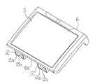
ここで、図1はディスプレイ6を付設したPOS端末1を概略的に示す外観斜視図である。図1に示すように、このPOS端末1の筐体である本体ケース2の操作者側から見て左側には、プリンタを内蔵してそのプリンタによって印字されるレシートを発行するレシート発行口3、ICカード等を挿入するカード挿入口4等が設けられている。一方、POS端末1の本体ケース2の操作者側から見て右側には、LCD5を主体に構成されて操作者側の表示部として機能して傾斜形状を有する扁平形状の表示装置であるディスプレイ6、各種のキーが集合するキーボード7、磁気カードを挿入する磁気カード挿入口8等が設けられている。また、ディスプレイ6は本体ケース2に形成されたディスプレイ6と略同一な容積を有する上面開放の凹部9(図2参照)に対して嵌合状態で内蔵されており、ディスプレイ6の下端前縁部6aと本体ケース2の表面とは視覚的に連続している。さらに、ディスプレイ6は、ディスプレイ6の下端前縁部6aにおいて回動自在とされている。
【0011】
次に、本体ケース2とディスプレイ6との取付構造について説明する。ここで、図2は本体ケース2におけるディスプレイ6の取付位置付近を部分的に示す外観斜視図、図3はディスプレイ6を本体ケース2から取り外した状態を示す斜視図である。図2に示すように、本体ケース2に形成された凹部9のキーボード7側端部に位置する底面には、二つのレール部10が形成されている。これらのレール部10には、本体ケース2の表面であって凹部9のキーボード7側に位置する上側端縁部9aを中心とした円の一部を構成して凹部9の底面に成形された曲面形状部材の一つである曲面10aと、この曲面10aの上部に支持部10bによって支持されていて曲面10aが構成する円よりも上側端縁部9aからの距離(半径)が近い(短い)同心円の一部を構成する曲面形状部材の一つである曲面10cとに挟まれた湾曲レール11が形成されている。
【0012】
一方、図3に示すように、ディスプレイ6の下方には、二つのアーム部12が形成されており、これらのアーム部12が本体ケース2に形成された二つのレール部10の曲面10aと曲面10cとの間にそれぞれ嵌合することにより、ディスプレイ6は本体ケース2に対して回動自在に連結される。つまり、レール部10とアーム部12とによって、連結機構B(図4参照)が構成されている。
【0013】
より詳細には、これらのアーム部12には、ディスプレイ6の下端前縁部6aを中心とした曲面形状部材である曲面12aが形成されている。この曲面12aは、本体ケース2にディスプレイ6を取り付けた場合において、レール部10の曲面10aが構成する円よりも半径が短くてレール部10の曲面10cが構成する円よりも半径が長い同心円の一部を構成するように形成されている。また、曲面12aの厚さは、レール部10の湾曲レール11を構成する曲面10aと曲面10cとの間隔よりも薄く形成されている。加えて、曲面12aには、レール部10の支持部10bの横断面形状に略同一な切欠12bが形成されている。この切欠12bは、本体ケース2にディスプレイ6を取り付けた場合において、アーム部12の曲面12aの位置決めの役目を果たすことになる。
【0014】
加えて、本体ケース2とディスプレイ6との間には、折り畳み・引き伸ばしが自在なロックヒンジユニット13(図4参照)が設けられており、本体ケース2とディスプレイ6とを連結している。このロックヒンジユニット13は、その関節部13aにおいて一定の摩擦力を有していることにより、ディスプレイ6を任意位置で固定することができ、傾斜保持手段として機能する。
【0015】
このような構成において、ディスプレイ6を本体ケース2に取り付けた状態について説明する。ここで、図4は本体ケース2に対するディスプレイ6の傾斜角が最も小さい場合における取り付け状態を示す縦断側面図である。図4に示すように、ディスプレイ6を本体ケース2に取り付けた状態においては、ディスプレイ6の下端前縁部6aと凹部9の上側端縁部9aとが線状に接触して連続した状態になっており、かつ、ディスプレイ6に備えられたアーム部12の曲面12aが本体ケース2に形成されたレール部10の湾曲レール11内に挿入された状態になっている。なお、ディスプレイ6の下端前縁部6aと凹部9の上側端縁部9aとの連続部位については、便宜上、接線Aとする。
【0016】
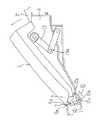
このような状態で、本体ケース2に対するディスプレイ6の傾斜角を大きくする場合(チルトさせる場合)には、ディスプレイ6の上端等を把持して引き上げる。ここで、図5はディスプレイ6を引き上げた場合における取り付け状態を示す縦断側面図である。図5に示すように、ディスプレイ6を引き上げた場合には、ディスプレイ6の下端前縁部6aと凹部9の上側端縁部9aとの接線Aを回転軸としてディスプレイ6が回動し、アーム部12の曲面12aが本体ケース2に形成されたレール部10の湾曲レール11内をその曲面形状に沿って摺動することになる。そして、所望の傾斜角になったところでディスプレイ6の移動を止めると、ロックヒンジユニット13の作用によってディスプレイ6が本体ケース2に対してロックされることになる。一方、このような任意の傾斜角での設定状態でディスプレイ6の傾斜角を小さくする場合には、ディスプレイ6の上端等を押し下げることにより、接線Aを回転軸としてディスプレイ6を回動させ、アーム部12の曲面12aをレール部10の湾曲レール11内で摺動させることになる。
【0017】
つまり、ディスプレイ6は、そのディスプレイ6の下端前縁部6aと本体ケース2に形成された凹部9の上側端縁部9aとの連続部位である接線Aを支軸とする回動軌跡に沿って、本体ケース2との連続性を維持したままで回動することになる。
【0018】
これにより、ディスプレイ6の下端前縁部6aと凹部9の上側端縁部9aとの連続部位である接線Aを回転軸としてディスプレイ6を回動させることになるので、回転軸の存在を感じさせることなくディスプレイ6を本体ケース2に対してチルト自在に取り付けることが可能になる。
【0019】
なお、本実施の形態においては、連結機構を構成するレール部10とアーム部12とをそれぞれ二つずつ設けたが、レール部10とアーム部12とがそれぞれ同数であれば、これに限るものではない。
【0020】
また、本実施の形態においては、傾斜保持手段としてロックヒンジユニット13を用いたが、これに限るものではなく、例えば本体ケース2とディスプレイ6との摩擦力によってディスプレイ6の傾斜を保持するようにしても良い。
【0021】
さらに、本実施の形態においては、表示装置としてPOS端末に付設されるディスプレイに適用したが、これに限るものではなく、その他の電子機器等に付設される表示装置に適用しても良い。
【0022】
【発明の効果】
請求項1記載の発明によれば、筐体と表示装置とを回動自在に連結する連結機構について、凹部に収納された表示装置の下端前縁部とその表示装置の下端前縁部に連続する筐体表面との連続部位を中心軸としてその中心軸からの距離がそれぞれ異なる同心円の一部を構成する少なくとも三以上の曲面形状部材を有し、一の曲面形状部材を他の曲面形状部材で摺動自在に挟み込むように凹部と表示装置とにそれぞれ配設して構成したことにより、連続部位を回転軸として表示装置を回動させた場合、一の曲面形状部材を他の曲面形状部材間で摺動させ、表示装置を傾斜保持手段によって任意傾斜角で保持し、筐体に対する表示装置の傾斜角を変化させることができるので、回転軸の存在を感じさせることなく表示装置を筐体に対してチルト自在に取り付けることができ、デザイン的に支障を来すことがなくなる。
【図面の簡単な説明】
【図1】本発明の実施の一形態のディスプレイを付設したPOS端末を概略的に示す外観斜視図である。
【図2】本体ケースにおけるディスプレイの取付位置付近を部分的に示す外観斜視図である。
【図3】ディスプレイを本体ケースから取り外した状態を示す斜視図である。
【図4】本体ケースに対するディスプレイの傾斜角が最も小さい場合における取り付け状態を示す縦断側面図である。
【図5】ディスプレイを引き上げた場合における取り付け状態を示す縦断側面図である。
【図6】従来の表示装置のチルト機構の一例を概略的に示す外観斜視図である。
【図7】従来の表示装置のチルト機構の別の一例を概略的に示す側面図である。
【符号の説明】
2 筐体
6 表示装置
6a 表示装置の下端前縁部
9 凹部
9a 筐体の表面
10a,10c,12a 曲面形状部材
13 傾斜保持手段
A 連続部位
B 連結機構[0001]
BACKGROUND OF THE INVENTION
The present invention relates to a tilt mechanism of a display device for holding a display device attached to a POS (Point of Sales: sales point management) terminal, which is a product sales registration data processing device, or other electronic devices at an arbitrary tilt angle. .
[0002]
[Prior art]
For example, a POS terminal, which is a merchandise sales registration data processing device used in a mass retailer or a specialty store, is provided with a thin flat display device mainly composed of an LCD (Liquid Crystal Display), for example. There are many cases. Further, in such a display device mainly composed of an LCD or the like, in order to provide a comfortable operating environment for each operator by adjusting the angle of the display device with respect to the operator operating the POS terminal, In many cases, a tilt mechanism that variably changes the tilt angle is provided.
[0003]
Here, FIG. 6 is an external perspective view schematically showing an example of a tilt mechanism of a conventional display device. As shown in FIG. 6, the
[0004]
On the other hand, FIG. 7 is a side view schematically showing another example of a tilt mechanism of a conventional display device. As shown in FIG. 7, the
[0005]
[Problems to be solved by the invention]
However, in the
[0006]
An object of the present invention is to provide a tilt mechanism of a display device that does not hinder design.
[0007]
[Means for Solving the Problems]
The invention according to claim 1 is a tilt mechanism of a display device that changes an inclination angle with respect to a housing of a flat display device, and is formed in the housing, and at least a surface of the housing and a lower end of the display device Concentric circles having different distances from the central axis with a concave portion that houses the display device so that the front edge portion is continuous, and a continuous portion between the surface of the housing and the lower front edge portion of the display device as a central axis And having at least three or more curved shape members respectively disposed in the recess and the display device, and one of the curved shape members is slidably sandwiched between the other curved shape members. The connecting mechanism for rotatably connecting the casing and the display device, and the tilt holding for holding the casing and the display device rotatably connected by these curved surface-shaped members at an arbitrary tilt angle Means.
[0008]
Therefore, the connecting mechanism for rotatably connecting the housing and the display device is a continuous part between the lower front edge of the display device housed in the recess and the housing surface continuous to the lower front edge of the display device. And having at least three curved surface-shaped members constituting part of concentric circles with different distances from the central axis, and one curved surface-shaped member is slidably sandwiched between other curved surface-shaped members Each of the recesses and the display device are arranged. Thereby, when the display device is rotated about the continuous portion as the rotation axis, one curved surface shape member slides between the other curved surface shape members, and the display device is held at an arbitrary inclination angle by the inclination holding means. The inclination angle of the display device with respect to the housing changes.
[0009]
DETAILED DESCRIPTION OF THE INVENTION
An embodiment of the present invention will be described with reference to FIGS. The display device of the present embodiment is applied to a display attached to a POS terminal used in a mass sales store or the like.
[0010]
Here, FIG. 1 is an external perspective view schematically showing a POS terminal 1 provided with a display 6. As shown in FIG. 1, on the left side of the main body case 2 which is the housing of the POS terminal 1 as viewed from the operator side, there is a receipt issuing port 3 for incorporating a printer and issuing a receipt printed by the printer. A card insertion slot 4 for inserting an IC card or the like is provided. On the other hand, on the right side of the main body case 2 of the POS terminal 1 as viewed from the operator side, the display 6 is a flat display device that is mainly composed of the LCD 5 and functions as a display unit on the operator side and has an inclined shape. A
[0011]
Next, a mounting structure between the main body case 2 and the display 6 will be described. Here, FIG. 2 is an external perspective view partially showing the vicinity of the attachment position of the display 6 in the main body case 2, and FIG. 3 is a perspective view showing a state where the display 6 is detached from the main body case 2. As shown in FIG. 2, two
[0012]
On the other hand, as shown in FIG. 3, two
[0013]
More specifically, the
[0014]
In addition, a lock hinge unit 13 (see FIG. 4) that can be folded and stretched is provided between the main body case 2 and the display 6, and connects the main body case 2 and the display 6. Since the
[0015]
A state in which the display 6 is attached to the main body case 2 in such a configuration will be described. Here, FIG. 4 is a longitudinal sectional side view showing an attachment state when the inclination angle of the display 6 with respect to the main body case 2 is the smallest. As shown in FIG. 4, when the display 6 is attached to the main body case 2, the lower
[0016]
In such a state, when the inclination angle of the display 6 with respect to the main body case 2 is increased (when tilted), the upper end of the display 6 is gripped and pulled up. Here, FIG. 5 is a vertical side view showing an attachment state when the display 6 is pulled up. As shown in FIG. 5, when the display 6 is pulled up, the display 6 rotates around the tangent line A between the lower
[0017]
In other words, the display 6 follows a rotation trajectory having a tangent A that is a continuous portion between the lower
[0018]
As a result, the display 6 is rotated about the tangent line A, which is a continuous portion between the lower
[0019]
In the present embodiment, two
[0020]
In this embodiment, the
[0021]
Furthermore, in this embodiment, the present invention is applied to a display attached to a POS terminal as a display device, but the present invention is not limited to this, and may be applied to a display device attached to another electronic device or the like.
[0022]
【The invention's effect】
According to the first aspect of the present invention, the connecting mechanism for rotatably connecting the housing and the display device is continuous with the lower front edge of the display device housed in the recess and the lower front edge of the display device. Having at least three curved surface-shaped members that form part of concentric circles each having a distance from the central axis that is a continuous portion with the surface of the housing that is the central axis, and one curved surface-shaped member as another curved surface-shaped member When the display device is rotated about the continuous portion as the rotation axis, the curved surface member is replaced with the other curved surface member. The display device can be held at an arbitrary tilt angle by the tilt holding means, and the tilt angle of the display device with respect to the housing can be changed. Tilt freely against Can be attached, it is not necessary to cause the design to trouble.
[Brief description of the drawings]
FIG. 1 is an external perspective view schematically showing a POS terminal provided with a display according to an embodiment of the present invention.
FIG. 2 is an external perspective view partially showing the vicinity of a display mounting position in a main body case.
FIG. 3 is a perspective view showing a state in which the display is removed from the main body case.
FIG. 4 is a longitudinal sectional side view showing an attachment state when the inclination angle of the display with respect to the main body case is the smallest.
FIG. 5 is a longitudinal sectional side view showing an attachment state when the display is pulled up.
FIG. 6 is an external perspective view schematically showing an example of a tilt mechanism of a conventional display device.
FIG. 7 is a side view schematically showing another example of a tilt mechanism of a conventional display device.
[Explanation of symbols]
2 Housing 6
Claims (1)
Translated fromJapanese前記筐体に形成され、少なくともその筐体の表面と前記表示装置の下端前縁部とが連続するように前記表示装置を収納する凹部と、
前記筐体の表面と前記表示装置の下端前縁部との連続部位を中心軸としてその中心軸からの距離がそれぞれ異なる同心円の一部を構成し、前記凹部と前記表示装置とにそれぞれ配設される少なくとも三以上の曲面形状部材を有し、一の前記曲面形状部材を他の前記曲面形状部材で摺動自在に挟み込んで前記筐体と前記表示装置とを回動自在に連結する連結機構と、
これらの曲面形状部材によって回動自在に連結された前記筐体と前記表示装置とを任意傾斜角で保持する傾斜保持手段と、
を備える表示装置のチルト機構。A tilt mechanism of a display device that changes an inclination angle with respect to a casing of a flat display device,
A recess that is formed in the housing and houses the display device so that at least the surface of the housing and the lower end front edge of the display device are continuous;
Contiguous parts of the surface of the housing and the lower end front edge of the display device are used as central axes to form part of concentric circles with different distances from the central axis, and are arranged in the recess and the display device, respectively. And a connecting mechanism for rotatably connecting the casing and the display device by slidably sandwiching one curved surface member with the other curved surface member. When,
Tilt holding means for holding the casing and the display device rotatably connected by these curved-surface-shaped members at an arbitrary tilt angle;
A tilt mechanism of a display device comprising:
Priority Applications (1)
| Application Number | Priority Date | Filing Date | Title |
|---|---|---|---|
| JP01601499AJP3632949B2 (en) | 1999-01-25 | 1999-01-25 | Tilt mechanism of display device |
Applications Claiming Priority (1)
| Application Number | Priority Date | Filing Date | Title |
|---|---|---|---|
| JP01601499AJP3632949B2 (en) | 1999-01-25 | 1999-01-25 | Tilt mechanism of display device |
Publications (2)
| Publication Number | Publication Date |
|---|---|
| JP2000214787A JP2000214787A (en) | 2000-08-04 |
| JP3632949B2true JP3632949B2 (en) | 2005-03-30 |
Family
ID=11904729
Family Applications (1)
| Application Number | Title | Priority Date | Filing Date |
|---|---|---|---|
| JP01601499AExpired - Fee RelatedJP3632949B2 (en) | 1999-01-25 | 1999-01-25 | Tilt mechanism of display device |
Country Status (1)
| Country | Link |
|---|---|
| JP (1) | JP3632949B2 (en) |
Families Citing this family (5)
| Publication number | Priority date | Publication date | Assignee | Title |
|---|---|---|---|---|
| KR100461184B1 (en)* | 2002-05-28 | 2004-12-13 | 삼성전자주식회사 | Display |
| CN101720482B (en)* | 2007-01-03 | 2014-02-26 | 迈尔史东视讯科技股份有限公司 | Device mount with selectively positionable tilt axis |
| PL384694A1 (en) | 2008-03-14 | 2009-09-28 | Furniture In Motion, Inc. | Display screen head, especially of a flat television screen |
| EP2329645A4 (en) | 2008-09-02 | 2011-11-30 | Milestone Av Technologies Llc | Low profile mount for flat panel electronic display |
| US8891249B2 (en) | 2009-01-07 | 2014-11-18 | Milestone Av Technologies Llc | Display mount with adjustable position tilt axis |
- 1999
- 1999-01-25JPJP01601499Apatent/JP3632949B2/ennot_activeExpired - Fee Related
Also Published As
| Publication number | Publication date |
|---|---|
| JP2000214787A (en) | 2000-08-04 |
Similar Documents
| Publication | Publication Date | Title |
|---|---|---|
| CN109521845B (en) | A car diagnostic tablet computer and its shell assembly | |
| US5796575A (en) | Portable computer with hinged cover having a window | |
| US6850407B2 (en) | Electronic apparatus having two housings coupled by hinge mechanism, one of which is reversible to the other | |
| KR100652783B1 (en) | Apparatus for automatically adjusting an angle of image unit for information processing equipment | |
| US6771494B2 (en) | Portable computer usable in laptop and tablet configurations | |
| KR200281313Y1 (en) | Computer display | |
| US7489525B2 (en) | Electronic device | |
| KR100878504B1 (en) | Dual monitor | |
| US20050122671A1 (en) | Electronic device with improved hinge | |
| CN101086275A (en) | Electronic apparatus | |
| US20080266768A1 (en) | Adjustable display | |
| JP3632949B2 (en) | Tilt mechanism of display device | |
| JP2001050244A (en) | Unit rotation support mechanism | |
| TWI727805B (en) | Notebook computer | |
| JP3463392B2 (en) | Electronics | |
| JPH03161816A (en) | Computer | |
| JP3632950B2 (en) | Tilt mechanism of display device | |
| KR100690908B1 (en) | Image unit automatic adjustment device of information processing equipment | |
| JPH04281509A (en) | Structure of a portable computer | |
| JPH06348364A (en) | Thin board type display screen inverting device | |
| JPH04221989A (en) | Electronic device | |
| JP3846434B2 (en) | Information processing apparatus with stand and display apparatus | |
| CN216647233U (en) | Electronic device with rotary control display module | |
| TWI876663B (en) | Handle device and electronic device | |
| JP3679670B2 (en) | Portable electronic devices |
Legal Events
| Date | Code | Title | Description |
|---|---|---|---|
| A977 | Report on retrieval | Free format text:JAPANESE INTERMEDIATE CODE: A971007 Effective date:20041125 | |
| TRDD | Decision of grant or rejection written | ||
| A01 | Written decision to grant a patent or to grant a registration (utility model) | Free format text:JAPANESE INTERMEDIATE CODE: A01 Effective date:20041216 | |
| A61 | First payment of annual fees (during grant procedure) | Free format text:JAPANESE INTERMEDIATE CODE: A61 Effective date:20041217 | |
| R150 | Certificate of patent or registration of utility model | Free format text:JAPANESE INTERMEDIATE CODE: R150 | |
| FPAY | Renewal fee payment (event date is renewal date of database) | Free format text:PAYMENT UNTIL: 20080107 Year of fee payment:3 | |
| FPAY | Renewal fee payment (event date is renewal date of database) | Free format text:PAYMENT UNTIL: 20090107 Year of fee payment:4 | |
| FPAY | Renewal fee payment (event date is renewal date of database) | Free format text:PAYMENT UNTIL: 20100107 Year of fee payment:5 | |
| FPAY | Renewal fee payment (event date is renewal date of database) | Free format text:PAYMENT UNTIL: 20100107 Year of fee payment:5 | |
| FPAY | Renewal fee payment (event date is renewal date of database) | Free format text:PAYMENT UNTIL: 20110107 Year of fee payment:6 | |
| FPAY | Renewal fee payment (event date is renewal date of database) | Free format text:PAYMENT UNTIL: 20110107 Year of fee payment:6 | |
| FPAY | Renewal fee payment (event date is renewal date of database) | Free format text:PAYMENT UNTIL: 20120107 Year of fee payment:7 | |
| FPAY | Renewal fee payment (event date is renewal date of database) | Free format text:PAYMENT UNTIL: 20120107 Year of fee payment:7 | |
| FPAY | Renewal fee payment (event date is renewal date of database) | Free format text:PAYMENT UNTIL: 20130107 Year of fee payment:8 | |
| LAPS | Cancellation because of no payment of annual fees |