JP3631848B2 - Image display system - Google Patents
Image display systemDownload PDFInfo
- Publication number
- JP3631848B2 JP3631848B2JP16888996AJP16888996AJP3631848B2JP 3631848 B2JP3631848 B2JP 3631848B2JP 16888996 AJP16888996 AJP 16888996AJP 16888996 AJP16888996 AJP 16888996AJP 3631848 B2JP3631848 B2JP 3631848B2
- Authority
- JP
- Japan
- Prior art keywords
- display
- image
- line
- unit
- data
- Prior art date
- Legal status (The legal status is an assumption and is not a legal conclusion. Google has not performed a legal analysis and makes no representation as to the accuracy of the status listed.)
- Expired - Fee Related
Links
Images


Classifications
- G—PHYSICS
- G09—EDUCATION; CRYPTOGRAPHY; DISPLAY; ADVERTISING; SEALS
- G09G—ARRANGEMENTS OR CIRCUITS FOR CONTROL OF INDICATING DEVICES USING STATIC MEANS TO PRESENT VARIABLE INFORMATION
- G09G3/00—Control arrangements or circuits, of interest only in connection with visual indicators other than cathode-ray tubes
- G09G3/001—Control arrangements or circuits, of interest only in connection with visual indicators other than cathode-ray tubes using specific devices not provided for in groups G09G3/02 - G09G3/36, e.g. using an intermediate record carrier such as a film slide; Projection systems; Display of non-alphanumerical information, solely or in combination with alphanumerical information, e.g. digital display on projected diapositive as background
- G09G3/002—Control arrangements or circuits, of interest only in connection with visual indicators other than cathode-ray tubes using specific devices not provided for in groups G09G3/02 - G09G3/36, e.g. using an intermediate record carrier such as a film slide; Projection systems; Display of non-alphanumerical information, solely or in combination with alphanumerical information, e.g. digital display on projected diapositive as background to project the image of a two-dimensional display, such as an array of light emitting or modulating elements or a CRT
- G—PHYSICS
- G06—COMPUTING OR CALCULATING; COUNTING
- G06F—ELECTRIC DIGITAL DATA PROCESSING
- G06F3/00—Input arrangements for transferring data to be processed into a form capable of being handled by the computer; Output arrangements for transferring data from processing unit to output unit, e.g. interface arrangements
- G06F3/14—Digital output to display device ; Cooperation and interconnection of the display device with other functional units
- G06F3/147—Digital output to display device ; Cooperation and interconnection of the display device with other functional units using display panels
- H—ELECTRICITY
- H04—ELECTRIC COMMUNICATION TECHNIQUE
- H04N—PICTORIAL COMMUNICATION, e.g. TELEVISION
- H04N5/00—Details of television systems
- H04N5/74—Projection arrangements for image reproduction, e.g. using eidophor
- H—ELECTRICITY
- H04—ELECTRIC COMMUNICATION TECHNIQUE
- H04N—PICTORIAL COMMUNICATION, e.g. TELEVISION
- H04N5/00—Details of television systems
- H04N5/74—Projection arrangements for image reproduction, e.g. using eidophor
- H04N5/7416—Projection arrangements for image reproduction, e.g. using eidophor involving the use of a spatial light modulator, e.g. a light valve, controlled by a video signal
- H04N5/7441—Projection arrangements for image reproduction, e.g. using eidophor involving the use of a spatial light modulator, e.g. a light valve, controlled by a video signal the modulator being an array of liquid crystal cells
- G—PHYSICS
- G09—EDUCATION; CRYPTOGRAPHY; DISPLAY; ADVERTISING; SEALS
- G09G—ARRANGEMENTS OR CIRCUITS FOR CONTROL OF INDICATING DEVICES USING STATIC MEANS TO PRESENT VARIABLE INFORMATION
- G09G2340/00—Aspects of display data processing
- G09G2340/04—Changes in size, position or resolution of an image
- G09G2340/0407—Resolution change, inclusive of the use of different resolutions for different screen areas
- H—ELECTRICITY
- H04—ELECTRIC COMMUNICATION TECHNIQUE
- H04N—PICTORIAL COMMUNICATION, e.g. TELEVISION
- H04N5/00—Details of television systems
- H04N5/74—Projection arrangements for image reproduction, e.g. using eidophor
- H04N5/7416—Projection arrangements for image reproduction, e.g. using eidophor involving the use of a spatial light modulator, e.g. a light valve, controlled by a video signal
- H04N5/7441—Projection arrangements for image reproduction, e.g. using eidophor involving the use of a spatial light modulator, e.g. a light valve, controlled by a video signal the modulator being an array of liquid crystal cells
- H04N2005/745—Control circuits therefor
- H—ELECTRICITY
- H04—ELECTRIC COMMUNICATION TECHNIQUE
- H04N—PICTORIAL COMMUNICATION, e.g. TELEVISION
- H04N5/00—Details of television systems
- H04N5/44—Receiver circuitry for the reception of television signals according to analogue transmission standards
- H04N5/445—Receiver circuitry for the reception of television signals according to analogue transmission standards for displaying additional information
- H04N5/45—Picture in picture, e.g. displaying simultaneously another television channel in a region of the screen
- H—ELECTRICITY
- H04—ELECTRIC COMMUNICATION TECHNIQUE
- H04N—PICTORIAL COMMUNICATION, e.g. TELEVISION
- H04N9/00—Details of colour television systems
- H04N9/12—Picture reproducers
Landscapes
- Engineering & Computer Science (AREA)
- Theoretical Computer Science (AREA)
- Signal Processing (AREA)
- General Physics & Mathematics (AREA)
- Multimedia (AREA)
- Physics & Mathematics (AREA)
- Computer Hardware Design (AREA)
- Chemical & Material Sciences (AREA)
- Crystallography & Structural Chemistry (AREA)
- Human Computer Interaction (AREA)
- General Engineering & Computer Science (AREA)
- Controls And Circuits For Display Device (AREA)
- Liquid Crystal Display Device Control (AREA)
- Digital Computer Display Output (AREA)
- Devices For Indicating Variable Information By Combining Individual Elements (AREA)
Description
Translated fromJapanese【0001】
【発明の属する技術分野】
本発明は、ビットマップデータに変換された画像データをパーソナルコンピュータ等の上位装置から液晶プロジェクタ等の表示装置に転送して画像を表示させるための画像表示システムに関し、特にプリンタ用インタフェースのようなデータ転送速度の低い既存の双方向インタフェースを使用して画像を高速表示させる画像表示システムに関する。
【0002】
【従来の技術】
従来、パーソナルコンピュータの表示装置としては、CRTディスプレイや液晶ディスプレイ等が多く利用されている。これらの表示装置はパーソナルコンピュータのディスプレイ用インタフェースに接続され、アナログRGB等の信号を転送して文字や画像を表示する。
【0003】
また近年にあっては、パーソナルコンピュータにプロジェクタ装置を外部接続してプレゼンテーションを効率的に行うようにした画像表示システムが数多く実用化されている。プレゼンテーションでは、パーソナルコンピュータのフレームメモリに展開した文書や画像などのビットマップデータ(ドットデータ)による画面を、プロジェクタに転送して同じ画面内容をスクリーン上に投影表示させる。
【0004】
プロジェクタは、通常、ハロゲンランプ等の光源と液晶パネル及びミラーやレンズ等の光学系等で構成される。表示駆動は、液晶パネルに表示したい画像を描画し、裏側から光源ランプで照らして透過した光でスクリーンに画像を投影して拡大表示する。液晶パネルとしては、アクティブドライブのTFT(Thin Film Transistor) 液晶パネル等が使用されている。
【0005】
【発明が解決しようとする課題】
しかしながら、現在、プロジェクタに使用したTFT液晶パネルで表示できる画素数は、640×480画素から1280×1024画素程度であり、このためパーソナルコンピュータ画面の文書や表をプロジェクタで拡大投影すると、画素数が少ないために文書や表などが読みにくくなる。
【0006】
そのためプロジェクタを利用したプレゼンテーションではパーソナルコンピュータの文書等の画像をそのまま利用できず、プロジェクタで拡大表示した際に良く見えるように、例えば文字サイズを大きくした文書画像等を改めて作成しなければならない繁雑さがあった。
また、現状のプロジェクタは、パーソナルコンピュータのディスプレイ画面と同じ画面を投影表示しているため、画面検索や切換えに等に必要な補助情報が得られず、その結果、プレゼンテーションの最中や質疑応答の際の画面選択や説明がやりにくいという問題があった。
【0007】
更に、現状のプロジェクタで表示できる画面は1つであり、文書やグラフ等の複数画面を1画面に入れて同時にスクリーン上に表示しようとしても、画面当りの画素数が少なくなるために画質が更に劣化し、画質を維持するためには画面切換えしかなく、プレゼンテーションの効率が悪いという問題もあった。
このようなプロジェクタの液晶パネルの画素数が少ない問題を解消するため、多画素・高解像度を実現する例えば相転移型液晶パネルを使用することが考えられる。相転移型の液晶パネルは、TFT液晶等のアクティブマトリクス駆動の液晶表示パネルに比べ、単純マトリクス駆動で構造が簡単なため、多画素化と高精細化に適しており、現在では2500×3500画素以上のA4サイズが実用化されている。
【0008】
相転移型液晶パネルは、透明なライン電極とデータ電極がマトリクス状に配置され、両者の交差位置の電極間に液晶材料を挟み込む構造になっている。また、マトリクス状の電極を電圧駆動するために、ライン電極ドライバとデータ電極ドライバの二つのドライバ回路を備えている。この相転移型液晶パネルの表示動作は、ライン電極ドライバで表示するライン電極を選択して電圧を印加する。
【0009】
一方、データ電極ドライバは、書き込む画素データ中の表示する画素と表示しない画素に応じた電圧を印加する。選択されたライン電極上の各画素の液晶は、電圧が印加されなければ入射光が散乱されるコレステリック相になり、光の透過率が低い「黒」の表示になる。反対に、電圧が印加されれば、光の透過率が高いネマティック相に転移して透明な「白」表示になる。
【0010】
このように、光の透過率の違いにより表示を行い、全ラインについて同様の処理を順番に繰り返すことで、画面全体の表示が達成される。また、相転移型液晶パネルはメモリ機能を持ち、一度書き込んだ表示データは保持電圧を印加しておくことにより、そのまま表示されている。
相転移型液晶パネルについての詳細は、例えば、
・相転移型プロジェクションディスプレイ(ディスプレイアンドイメージング,1992, Vol.1, No1, pp.61−69. )
・A5−Mpixel overhead projection display utilizing a nematic−cholesteric phase−transition liquid crystal. (Journal of the Society for Information Display, Vol.1, No.1, 1993. pp43−49. )
に記載される。
【0011】
このように相転移型液晶パネルは、高解像度であり、光の透過率が高く画面が明るい反面、表示速度が遅く、TFT液晶パネルに比較して画面の書換時間が遅いことが問題となっている。即ち、黒(散乱状態)から白(透明状態)に書き換えるためには数十ミリ秒かかり、逆に白(透明状態)から黒(散乱状態)に書き換えるためには数ミリ秒の書込時間を要する。例えば2500ライン×3500画素の相転移型液晶パネルを、初期化した後に画像を表示するためには、20秒近くかかってしまう。
【0012】
相転移型液晶パネルの画面書換え時間が遅い問題を解決するため、従来の表示制御では、前の画面と新しい画面のデータを常に比較し、異なる部分だけを書き換えることによって書換時間を短縮している(特開昭61−138991号、特開平2−217893号、特開平7−5845号等)。
しかし、新しい画面と前の画面との異なる部分だけを書き換える従来の表示制御にあっては、動画のように連続する内容をもつ画面を切り換える場合には効果があるが、プレゼンテーション等のために主に静止画像を表示するプロジェクタでは、画面内容がその都度、全く異なってしまう場合が多く、前の画面と異なる部分だけを書き換えても書換時間の短縮は期待できず、この点の改善が必要となる。
【0013】
更に、プロジェクタをパーソナルコンピュータに外部表示装置として接続して画面データを転送表示する場合、インタフェースに何を使用するかが問題になる。パーソナルコンピュータのディスプレイ用インタフェースは、アナログRGB等の信号を転送して文字や画像を表示する。しかし、ディスプレイ用インタフェースは、アナログで高速であるが片方向転送しかできず、表示装置からパーソナルコンピュータへの信号転送はできず、双方向転送を必要とするプロジェクタには使用できない。
【0014】
パーソナルコンピュータ用のインタフェースとしては、この他にプリンタ装置を接続するためのIEEE1284等のパラレルインタフェースが知られており、このインタフェースはディジタルで双方向のインタフェースであり、またビットマップデータを転送していることから、プロジェクタに対する画像データの転送に適している。
【0015】
しかし、プリンタ用双方向インタフェースとして知られた例えばセントロニクスインタフェース等でプリンタにデータを送る場合、転送速度は100Kバイト/秒程度であり、相転移型液晶パネルの多画素表示に相当する300dpiのA4モノクロデータは、約1Mバイトとなるため、画像データの転送に10秒程度の時間がかかる。パーソナルコンピュータ用のプリンタの印刷速度は、例えばインクジェットプリンタでA4、1枚当り30秒から1分程度かかり、データ転送速度は問題にならない。
【0016】
しかし、プロジェクタ等の表示装置では、表示速度の遅い相転移型液晶パネルでも、数秒で1画面を表示でき、プリンタ用双方向インタフェースでは、転送速度によって表示速度が制限されるという問題がある。このためパーソナルコンピュータに標準装備されているプリンタ用インタフェースを使用してプロジェクタを接続することができず、転送速度の高い専用のインタフェースを別途設けなければならず、汎用性に欠ける。
【0017】
更に、相転移型液晶パネルの表示速度の改善が図られても、プリンタ用インタフェースではデータ転送速度が表示速度に追い付かず、表示速度がデータ転送速度により制約される問題が起きる。
本発明の目的は、プロジェクタ等の表示速度を制限することなく既存のプリンタ用インタフェースを使用して画像データを転送できる画像表示システムを提供する。
【0018】
また本発明の他の目的は、表示装置としてプロジェクタを使用し、パーソナルコンピュータから主画面及び補助画面の2画面を転送してスクリーン上に個別の表示パネルを使用して高品質に表示できる画像表示システムを提供する。
さらに本発明の他の目的は、プロジェクタに相転移型液晶パネルを使用した場合の表示速度を高速化する画像表示システムを提供する。
【0019】
【課題を解決するための手段】
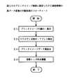
図1は本発明の原理説明図である。本発明は、図1(A)のように、上位装置10としての例えばパーソナルコンピュータから画像データを表示装置12に転送して表示させる画像表示システムである。上位装置には、ビットマップデータに展開された画像データを格納した画像データ格納部、画像データ格納部の画像データを読み出して圧縮する圧縮部、及び圧縮部で圧縮された画像データを表示装置に転送する双方向伝送機能を備えた第1インタフェースを設ける。
【0020】
また表示装置12には、上位装置10から転送された圧縮画像データを受信する双方向伝送機能を備えた第2インタフェース、第2インタフェース部で受信した圧縮画像データの復号により元の画像データを復元する復号部、及び復号部で復号された画像データを可視化表示させるディスプレイユニットを設ける。
そして、描画コントローラは、ディスプレイユニットに書込表示する表示ラインの順番を設定する表示ライン設定部と、表示ライン設定部で設定された順番に従って、表示装置用画像データ格納部から画像ラインデータを読み出して画像ラインデータを書込用ラインデータとしてラインデータ格納部に格納する読出部と、読出部で画像ラインデータを読出す毎に、画像ラインデータとラインデータ格納部に格納した各書込用ラインデータとを比較して表示装置用画像データ格納部から読み出された画像ラインデータに書き込みを要する表示画素を含んでいる場合は表示装置用画像データ格納部から読み出された画像ラインデータをディスプレイユニットに対する書込表示ラインとして検出する書込ライン検出部と、書込ライン検出部で書込表示ラインであるとして検出した表示ラインに対応するディスプレイの表示ラインの全てへ同時に読出部で読み出した画像ラインデータを書き込んで表示させる表示駆動部と、を備えている。
ここで第1及び第2インタフェースには、双方向伝送機能を備えたプリンタ用のパラレル・インタフェースを使用する。また第1及び第2インタフェースのデータ転送速度に対し、ディスプレイユニットの表示速度が速い関係にある。
【0021】
このように本発明の画像データ表示システムにあっては、上位装置と表示装置を接続するインタフェースのデータ転送速度が表示速度より低くとも、画像データを圧縮転送していることから、圧縮率に応じてデータ転送速度を増加させることができ、データ表示速度を制約することなく低速のプリンタ用インタフェースを使用して画像データを効率良く転送することができる。
【0022】
また本発明の別の形態として、図1(B)のように、上位装置10に、表示装置12へ転送する第1画像データ及び自己のディスプレイに表示する第2画像データを格納した画像データ格納部、画像データ格納部の第1画像データを読み出して圧縮する圧縮部、圧縮部で圧縮された第1画像データを表示装置に転送する上位側双方向インタフェースに加え、上位装置自身のディスプレイに表示可能な画像データ格納部の第2画像データを表示装置12に送信する送信インタフェースを設ける。
【0023】
これに対応して表示装置12には、上位装置10から転送された圧縮画像データを受信する表示側双方向インタフェース、上位装置から転送された圧縮画像データの復号により元の第1画像データを復元する復号部、復号部で復号された第1画像データをディスプレイユニットに表示させる描画コントローラを設け、更に、上位装置12から送信された第2画像データを受信する受信インタフェース、受信インタフェースで受信した第2画像データをディスプレイユニットに表示させるディスプレイ・コントローラを設ける。
【0024】
この場合にも、上位側及び表示側双方向インタフェースは、プリンタ用の双方向転送機能を備えたパラレルインタフェースであり、一方、送信インタフェース及び受信インタフェースは、片方向転送機能を備えたディスプレイ用インタフェースである。更に、上位側インタフェースと表示側インタフェース間のデータ転送速度に対し、ディスプレイユニットの表示速度が速い関係にある。
【0025】
本発明の表示装置のディスプレイユニットは、例えば表示パネルの表示画像を光学的にスクリーン上に投影して表示するプロジェクタ・ユニットである。プロジェクタ・ユニットは、描画コントローラで描画した第1画像をスクリーンに投影表示する第1表示パネル、ディスプレイ・コントローラで描画した第2画像をスクリーンに投影表示する第2表示パネル、及びスクリーン上における第1画像と第2画像の表示位置と表示サイズを調整する調整部を備える。
【0026】
これによってプロジェクタのスクリーン上に各々独立した表示パネルの描画によって、2画面が投影表示できる。この場合、スクリーン上の第1画面がプレゼンテーションに使用するメインの拡大表示画面であり、その中に、サイズの小さな第2画面によって、プレゼンテーションの説明に必要なガイダンスや画面情報等の補助的な情報が鮮明に表示できる。
【0027】
プロジェクタの調整部は、第1表示パネル及び第2表示パネルの投影位置及び倍率を独立に調整可能な投影光学ユニットである。具体的には、調整部は、スクリーン全体に前記第1表示パネルの第1画像を拡大表示すると共に、スクリーンの一部に第2表示パネルの第2画像を小さいサイズで重ねて表示する。この場合の第2画像の表示サイズは、上位装置に設けているディスプレイ画面と同じ程度のサイズとする。
【0028】
2画面の重ね表示を適切とするため、描画コントローラは、スクリーン上に投影表示された第1画像に重ねて表示する第2画像の表示領域の相当する画像部分を黒データに変換して第1表示パネルに第1画像を描画し、第1画像の黒データ描画によるスクリーン上の画像の抜け部分に第2画像を投影表示させる。第1描画コントローラは、プロジェクタ・ユニットからスクリーンまでの距離、方向、倍率に基づいて、予め定めた第2画像の表示サイズに相当する画像データの領域を黒データに変換する。
【0029】
プロジェクタ・ユニットは、第1表示パネル及び第2表示パネルとして、相転移型の液晶パネルを使用する。描画コントローラは、液晶表示パネルに書込表示する表示ラインの順番を設定する表示ライン設定部、表示ライン設定部で設定された順番に従って、画像データ格納部からラインデータを読み出す読出部、読出部でラインデータを読み出す毎に、そのラインデータと画像データ格納部の各ラインデータとを比較して液晶表示パネルに対する書込表示ラインを検出する書込ライン検出部、及び表示ライン検出部で検出した1又は複数の液晶表示パネルの表示ラインに、読出部で読み出したラインデータを書き込んで表示させる。
【0030】
このような相転移型の液晶パネルの書込表示により、1回の書込みで同時に複数ラインの書込表示が行われ、全ラインの書込みを行う前、全画素の書込表示を完了することができる。特に、表示ラインに直交する方向に表示画素が並んでいるような画像データについては、各ラインに共通なラインデータによる同時書込みが効率的に行われ、極めて短時間で書込表示が完了する。例えば正方形や長方形の矩形画像にあっては、表示画素が現われる先頭ラインの書込処理のみで、全画素の書込表示が完了する。
【0031】
また複数ライン対し共通に存在する数の多い表示画素の順番に、複数ラインの同時書込みによる表示が行われることとなり、書込初期では概略的に画像が現われ、時間の経過に伴って詳細な表示に切り換わっていくという階層的な表示機能を本質的にもっている。このため、画面検索等では、書込初期の段階で画像の概略を認識することができ、画面切換えによる検索もかなり高速でできる。
【0032】
例えばグラフや表のように表示ラインに直交する罫線(縦罫線)を含む文書画像データにあっては、書込み初期の段階で、縦罫線が一括表示され、この画像が表やグラフを含んでいることが、直ちに認識できる。
ここで読出部は、読み出したラインデータが液晶パネルに書込みを必要とする表示画素を含むか否か検出する表示画素検出部を備え、表示画素を含まない場合は、書込ライン検出部及び表示部をスキップして次の表示ラインの読出しを行う。これによって表示画素を含まないラインデータは書込処理から除外され、その分、表示速度が向上する。
【0033】
書込ライン検出部は、画像データ格納部の中から読出部による読出ラインデータと同じ表示ラインを検出する。これは、現在処理対象となっている表示ラインと他のラインとの表示画素の論理積を求めることに相当し、同一のラインデータを複数ラインに同時書込みすることで、表示速度が向上する。
また書込ライン検出部は、画像データ格納部の中から読出部による読出ラインデータを一部に含む表示ラインを検出する。これは、現在処理対象となっている表示ラインの表示画素を含む他のラインを検出し、処理対象ラインのラインデータを検出した複数ラインに同時に書き込むことで、1回に書き込む画素数を可能な限り多くして、表示速度を向上させる。
【0034】
表示駆動部は、液晶パネルに書き込まれていない画素にのみ書き込む追加書込みを行う。また表示部は、既に書き込まれている画素にも重ねて書き込むこともできる。
書込ライン検出部は、検出された表示ラインの表示画素が既に全て書き込まれている場合には、この検出ラインを書込みラインから除外する。具体的には、書込みを行うごとに、画像データ格納部の中の書込済みの表示画素を消去し、書込みが済んでいない表示画素について表示処理を繰り返せばよい。
【0035】
処理ライン設定部は、表示ユニットの表示ラインを先頭から順番に指定して読出部によりラインデータを読み出させる。またラインデータに含まれる表示画素数の少ない順番に指定してラインデータを読み出させてもよい。表示画素数の少ないラインデータほど、これを含む他のラインデータが多いことから、1回に書き込む表示ラインの数が増加し、より効率的な書込表示が期待できる。
【0036】
更に本発明はプロジェクタそのものを提供する。このプロジェクタは、描画コントローラにより描画される第1画像をスクリーンに投影表示する第1表示パネル、ディスプレイコントローラにより描画される第2画像をスクリーンに投影表示する第2表示パネル、及びスクリーン上における第1画像と第2画像の表示位置と表示サイズを調整する調整部を備える。この場合も、描画コントローラは、スクリーン上に投影表示された第1画像に重ねて表示する第2画像の表示領域の相当する画像部分を黒データに変換して第1表示パネルに第1画像を描画し、第1画像の黒データ描画によるスクリーン上の画像の抜け部分に第2画像を投影表示させる。
【0037】
【発明の実施の形態】
<目 次>
1.プリンタインタフェースによる多画素転送表示
2.相転移型液晶パネルの高速表示
3.プロジェクタ2画面の表示制御
1.プリンタインタフェースによる多画素転送表示
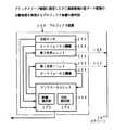
図2は本発明の画像表示システムの実施形態の説明図である。図2において、本発明の画像表示システムは、上位装置としてのパーソナルコンピュータ10と、パーソナルコンピュータ10の外部表示装置として接続されるプロジェクタ装置12で構成される。パーソナルコンピュータ10は液晶ディスプレイ10−1を備えており、液晶ディスプレイ10−1はTFT液晶パネルを用いたもので、例えば640×480画素から1280×1024画素程度の画素数を有する。
【0038】
プロジェクタ装置12は、パーソナルコンピュータ10にインタフェースケーブル34によって接続される。このパーソナルコンピュータ10とプロジェクタ装置12を接続するインタフェースは、パーソナルコンピュータ用のプリンタに使用されている双方向パラレルインタフェースを使用しており、例えばIEEE1284に準拠したセントロニクスインタフェース等が使用される。
【0039】
プロジェクタ装置12は内部に液晶パネルを内蔵しており、パーソナルコンピュータ10から転送された画像を液晶パネルに描画し、光源からの光の投射によって分離配置されたスクリーン15上にプロジェクタ画像12−1を表示する。本発明のプロジェクタ装置12で使用している液晶パネルは、相転移型液晶パネルであり、その画素数は例えば2000×2000画素の400万画素を実現しており、スクリーン15上のプロジェクタ画像12−1としては、A4サイズで300dpiのプリンタ印刷と同等な高画質を実現することができる。
【0040】
図3は図2のプロジェクタ装置12の実施形態である。図3のプロジェクタ装置12はモノクロ画像の表示を例にとっており、コントロールユニット62と光学ユニット64を備える。光学ユニット64はハロゲンランプ等を用いた光源66を有し、光源66からの光をディフレクタ68で前方に照射している。光源66からの光は集光レンズ70で集光され、液晶パネル52を透過した後、投影レンズ72によりスクリーン15上に拡大表示される。投影レンズ72としては、必要に応じてオートフォーカス機構やズーム機構を設けることができる。
【0041】
図4は図2のプロジェクタ装置12の他の実施形態であり、このプロジェクタ装置12はカラープロジェクタとしたことを特徴とする。プロジェクタ装置12にはコントロールユニット162とカラー光学ユニット164が設けられている。カラー光学ユニット164はディフレクタ168を備えた光源166からの白色光を反射ミラー200で反射した後、ダイクロイックミラー202に入射している。
【0042】
ダイクロイックミラー202は波長選択性をもち、赤成分Rを反射し、それ以外の波長成分を透過する。ダイクロイックミラー202で反射された赤成分Rは、反射ミラー204から液晶パネル52−1に入射される。液晶パネル52−1はコントロールユニット162により赤成分Rの画像で描画駆動されており、したがって描画画像に対応した赤成分Rの画像光を出力する。
【0043】
ダイクロイックミラー202を透過した赤成分R以外の光はダイクロイックミラー206に入射し、青成分Bが反射して他の波長成分は透過する。ダイクロイックミラー206で反射された青成分Bは液晶パネル52−2を透過する。液晶パネル52−2はコントロールユニット162により青成分Bの画像により描画されており、青成分Bの画像に対応した画像成分を出力する。
【0044】
ダイクロイックミラー206を透過した光は残りの緑成分Gであり、緑成分Gは液晶パネル52−3を透過する。液晶パネル52−3は、コントロールユニット162により緑成分Rの画像データによる描画が行われており、緑成分Gの画像描画に対応した画像光を出力している。
液晶パネル52−1からの赤成分Rの画像光と液晶パネル52−2からの青成分Bの画像光は、ダイクロイックミラー208で合成される。続いてダイクロイックミラー212で液晶パネル52−3からの反射ミラー210で反射された緑成分Gの画像光が合成され、これによりRGB3成分の合成画像光が得られる。最終的にRGB合成画像光は投影レンズ214に入射し、スクリーン15上にカラー画像を投射して表示する。
【0045】
図5は図2の画像表示システムの回路構成の実施形態である。上位装置としてのパーソナルコンピュータ10にはMPU14が設けられる。MPU14はシステムバス30及びデータバス32を有する。MPU14に対してはシステムバス30を介してプログラムメモリとして機能するROM16及び、データメモリもしくはワークメモリとして機能するRAM18が接続される。またRAM18はデータバス32にも接続される。
【0046】
フレームメモリ20には、出力表示する画像データがビットマップデータ(ドットデータ)に展開されて格納される。外部接続されるプロジェクタ装置12に対する転送回路部として、圧縮部22と上位側の双方向インタフェース24が設けられる。圧縮部22はプロジェクタ装置12に転送する画像データを圧縮して双方向インタフェース24に出力する。
【0047】
圧縮部22による圧縮アルゴリズムとしては、ビットマップデータ(ドットデータ)の圧縮法として知られたファクシミリ装置などと同じ例えばMMR符号化アルゴリズムを使用する。圧縮部22による圧縮処理としては、MPU14によるソフトウェアとして実現してもよいし、専用のファームウェアもしくはハードウェアとして実現することもできる。
【0048】
更にパーソナルコンピュータ10には、ディスプレイインタフェース26を介してディスプレイユニット28が接続されている。ディスプレイユニット28は図2の液晶ディスプレイ10−1を備える。液晶ディスプレイ10−1としてはTFT型液晶パネルを使用しており、画素数としては640×480画素から1280×1024画素程度である。ディスプレイインタフェース26は周知のアナログインタフェースであり、ディスプレイユニット28側にのみ画像データを転送できる片方向転送機能を有する。
【0049】
パーソナルコンピュータ10によるプロジェクタ装置12に対する画像の出力表示は、RAM18に展開されたアプリケーションプログラムとしてのドライバモジュール17を印刷メニューによって起動させることで実現できる。即ち、印刷メニューによるドライバモジュール17の起動により、MPU14はフレームメモリ20にプロジェクタ装置12で表示するための画像情報をビットマップ展開する。
【0050】
続いてビットマップ展開した画像データを例えば水平方向のラインデータ単位に圧縮部22に読み出して、MMR符号化などにより符号データに変換し、双方向インタフェース24によりインタフェースケーブル34を介してプロジェクタ装置12に転送する。
ここでパーソナルコンピュータ10とプロジェクタ装置12を接続しているプリンタ用双方向転送機能を備えたパラレルインタフェース、即ちIEEE1284準拠のインタフェースにあっては、データ転送速度が100Kバイト/秒程度であり、プロジェクタ装置12で表示させるA4サイズで300bps相当の表示に必要なデータ量は約1Mバイトであることから、そのまま転送すると10秒程度かかってしまう。
【0051】
しかしながら、本発明の画像表示システムにあっては、フレームメモリ20における1Mバイト程度の画像データを圧縮部22においてMMR符号化して符号データに変換しているため、例えば圧縮率が1/2であったならば半分程度の500Kバイトに圧縮でき、プロジェクタ装置12の表示速度が例えば1画面当たり数秒であることから、このプロジェクタ装置12の表示速度に見合ったデータ転送速度を実質的に実現することができる。
【0052】
実際のMMR符号化にあっては、その圧縮率は1/2以下とすることができ、文書データなどの画像データであれば更に圧縮率が向上して、1,2分で1画面分の画像データをプロジェクタ装置12に転送することができ、実質的にプロジェクタ装置12の表示速度を十分上回る画像データの転送速度が実現できる。
次にプロジェクタ装置を説明する。プロジェクタ装置12には、システムバス58及びデータバス60を備えたMPU36が設けられ、MPU36に対しプログラムメモリとしてのROM38、プリンタ用双方向パラレルインタフェースの表示装置側の双方向インタフェース40、復号部42、フレームメモリ44を接続している。
【0053】
双方向インタフェース40で受信されたパーソナルコンピュータ10からの符号データは復号部42に与えられ、MMR復号化により元の画像データが復元され、フレームメモリ44に格納される。フレームメモリ44に格納された画像データは描画コントローラ46により読み出され、ドライブコントローラ48を介してディスプレイユニット50に表示される。
【0054】
ディスプレイユニット50は液晶パネル52、ライン電極ドライバ54及びデータ電極デバイス56を備える。液晶パネル52としては、本発明にあっては、相転移型の液晶パネルを使用しており、その画素数は現在では2500×3500画素以上のA4サイズのものが実用化されているが、この実施形態にあっては2000×2000画素をもった400万画素のものを使用している。
【0055】
図6は図5のディスプレイユニット50における液晶パネル52の概略である。相転移型の液晶パネル52は、M×N画素のマトリクス駆動型のデバイス構造をもっている。即ち、ライン電極ドライバ54に接続された透明なライン電極L1〜LNと、データ電極ドライバ56に接続されたデータ電極D1〜DMがマトリクス状に配置されており、両者の交差位置の電極間に液晶材料を挟み込んで、表示画素となる液晶セル74−11〜74−MNを形成している。
【0056】
この相転移型液晶パネル52の表示動作は、まずライン電極ドライバ54に対するライン番号の指定でライン電極L1〜LNの中から1または複数のラインを選択してライン電圧を印加する。同時にデータ電極ドライバ56に対しては1ライン分のラインデータ即ちM個の画素データが与えられ、このライン画素データに応じた電圧をデータ電極D1〜DMに印加する。例えば画素データ1でデータ電極に電圧が印加され、画素データ0で電圧の印加を解除する。
【0057】
ライン電極ドライバ56で選択されたライン電極上の各液晶セルは、データ電極ドライバ56側の画素データ「0」により電圧が印加されなければ、入射光が散乱されるコレステリック相となり、光の透過率が低い黒の表示になる。反対にデータ電極ドライバ56側から画素データ「1」に対応して電圧が印加されれば、光の透過率が高いネマティック相に転移し、透明な白表示となる。
したがってライン電極ドライバ54で選択したライン電極の液晶セルに対するデータ電極ドライバ56による画素データの1,0に応じた電圧印加の有無により、液晶セルの透過率を変えて画像をドットイメージにより表示する。更に相転移型の液晶パネル52はメモリ機能をもち、一度液晶セルに書き込んだ表示データは、保持電圧を印加しておくことでそのまま表示状態を維持できる。
【0058】
更に書込動作時間としては、保持電圧を解除して行う黒「1」から白「0」への書込みには数十秒かかり、また保持電圧を印加して行う白「0」から黒「1」への書込みには数ミリ秒かかる。通常、画像を書き込む前には液晶パネル52の全セルを白「0」に初期化しておき、その後に画素データによる黒「1」の書込みを行う。
【0059】
液晶パネル52の初期化即ち全セルを白「0」に書き込むためには、ライン電極L1〜LNの全てに電圧を加えた状態でデータ電極ドライバ56による全てのデータ電極ドライバD1〜DMの保持電圧をゼロボルトにすればよい。
再び図5を参照するに、図6のような2000×2000画素で合計400万画素という極めて表示精度の高い多画素の液晶パネル52をプロジェクタ装置12に設けているため、図2のようにプロジェクタ装置12によってスクリーン15上に表示されるプロジェクタ画像12−1は300dpiのプリンタ印刷画像と同等な極めて高品質の画像表示とすることができる。
【0060】
しかも1画面当たり約1Mバイトのデータ転送を既存のプリンタ用双方向パラレルインタフェースを使用して行っているが、この画像データの転送の際に圧縮を行うことで実質的にデータ転送速度を高め、データ転送速度に制約されることなく、プロジェクタ装置12において高品質な画像を表示することができる。
2.相転移型液晶パネルの高速表示
図7は図5のプロジェクタ装置12に設けた描画コントローラ46の実施形態であり、本発明による画像表示方法による書込表示を相転移型の液晶パネル52に対し行う。
【0061】
描画コントローラ46はタイミング制御部78、表示ライン設定部80、ラインデータ格納部82、書込ライン番号検出部84及びフレーム消去部86で構成される。タイミング制御部78は上位装置としてのパーソナルコンピュータ10側からの書込起動信号E0を受けて、描画コントローラ46及びメモリ制御部76、更にはドライブコントローラ48に対するタイミング信号を出力する。
【0062】
ここで描画コントローラ46は、書込起動信号E0を受けた際に、まず液晶パネル52の全面消去による初期化を行った後に、画像データの書込表示を行う。また書込開始に先立って、フレームメモリ44の表示画像メモリ領域44−1には画像データが格納されている。
即ち、フレームメモリ44は、表示画像メモリ領域44−1とワークメモリ領域44−2を備えており、画像データは表示画像メモリ領域44−1にオリジナルとして保存されており、書込動作の際にはワークメモリ領域44−2に展開し、書込画素の消去などの処理を行う。
【0063】
描画コントローラ46に設けた表示ライン設定部80は、液晶パネル52に対する書込ラインの順番を予め設定している。この実施形態にあっては、表示ライン設定部80は、表示ラインの順番(昇順)又は画素数の少ない順に設定する。
表示ライン設定部80による順番設定が行われた書込ラインの情報は、タイミング制御部78からのタイミング制御信号を受けるごとにメモリ制御部76をアクセスし、設定された書込ラインに対応する画像のラインデータをフレームメモリ44のワークメモリ領域44−2から読み出してラインデータ格納部82に格納する。同時に、同じラインデータを書込ライン番号検出部84に格納する。
【0064】
書込ライン番号検出部84は、ワークメモリ領域44−2から順次読み出されるラインデータと、ラインデータ格納部82に格納した現在処理対象となっている表示ラインのラインデータとを比較し、ラインデータ格納部80のラインデータの表示画素、即ち黒「1」の画素データを書込ライン番号検出部84に読み出したラインデータが含むか否か検出し、含んでいる場合には、そのラインを今回の書込ライン番号として検出する。
【0065】
尚、書込ライン番号検出部84にあっては、最初のラインデータ格納部82に現在処理対象としているラインデータの格納時にも同じラインデータが入力されて比較されることから、現在処理対象となる表示ラインについても書込ライン番号検出部84で書込番号の検出が行われている。
ここで現在処理対象となった書込ラインのラインデータをラインデータ格納部82及び書込ライン番号検出部84に格納した際に、ラインデータの中に表示画素を含まない場合には、これをタイミング制御部78に通知し、このラインについては書込処理を行わずに、次の表示ラインの書込処理にスキップする。
【0066】
書込ライン番号検出部84でラインデータ格納部82の現在処理対象となっているラインデータを含む書込ライン番号の検出が済むと、ドライブコントローラ48に対しラインデータ信号E1及び書込ライン番号信号E2が供給され、ライン電極ドライバ54とデータ電極ドライバ56の駆動で液晶パネル52にラインデータ格納部82のラインデータを同時に書込表示する。
【0067】
ドライブコントローラ48による液晶パネル52へのラインデータの書込みが済んだならば、フレーム消去部86がメモリ制御部76を介してフレームメモリ44のワークメモリ領域44−2に格納している画像データの中の書込画素を消去する。このような処理を表示ライン設定部80で設定される表示ラインの順番に従って順次指定し、ワークメモリ領域44−2の中に表示画素がなくなった時点で書込表示を終了する。
【0068】
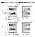
図8、図9及び図10は、図7の実施形態による書込表示の動作説明図である。図8(A)はフレームメモリ44の表示画像メモリ領域44−1であり、説明を簡単にするため、液晶パネル52を8ライン×8画素の合計64画素構成とした場合を例にとっている。ここで画像データにおける表示ラインL1〜L8の表示画素数は、右側に取り出して示すように、「03455434」となる。この場合、表示ライン設定部80はライン番号L1〜L8の順にライン選択順位を設定している。
【0069】
図8(A)の表示画像メモリ領域44−1の画像データを液晶パネル52に書込表示する場合、まず表示ラインL1が設定され、ワークメモリ領域44−2よりラインL1のラインデータがラインデータ格納部82及び書込ライン番号検出部84に読み出される。しかしながら、ラインL1については表示画素が存在しないことから、ラインL1の書込表示は行わず、次のラインL2の処理に進む。
【0070】
図8(B)は、ラインL2の書込表示における液晶パネル52の表示内容とワークメモリ領域44−2の書込後の消去状態を表わしている。まず表示ラインとしてラインL2が設定されると、図8(A)の画像データと同じワークメモリ領域44−2のラインL2のラインデータ「11100000」が読み出され、ラインデータ格納部82に格納されると同時に、書込ライン番号検出部84に格納され、書込ラインとして最初のラインL2が検出される。
【0071】
続いて次のラインL3のラインデータが読み出されて、書込ライン番号検出部84でラインL2のラインデータと比較される。ラインL3にはラインL2の表示画素が含まれていることから、ラインL3が書込ラインとして検出される。残りのラインL4〜L8については、現在処理対象となっているラインL2の表示画素を全て含まないことから、書込ラインとしての検出は行われない。
【0072】
このため液晶パネル42のラインL2の書込動作では、書込ライン番号L2,L3の2ラインが指定され、ラインL2の表示画素であるデータ電極D1,D2,D3が1となって電圧が印加され、これによって液晶パネル42に新規書込みが行われる。書込みが済むと、図8(B)のワークメモリ領域44−2のように、ラインL2,L3の各々の3つの表示画素の消去が行われる。
【0073】
そして消去後に次のラインL3が表示ライン設定部80により設定され、図8(C)のラインL3のラインデータ「00011000」による書込表示を行う。ラインL3のラインデータ「00011000」の表示画素は、ラインL4〜L8に含まれていることから、このライン番号が検出され、ラインL3〜L8の6ラインに対する同じラインデータの同時書込みが行われる。そして書込画素が図8(C)のワークメモリ領域44−2に示すように消去され、次のラインL4が設定される。
【0074】
図9(D)はラインL4の設定による書込表示であり、この場合にはラインL4に加えてラインL8が検出され、ラインL4,L8の2ラインに同じラインデータの書込みが行われ、表示画素の消去後に次のラインL5が設定される。図9(E)はラインL5の書込表示であり、この場合は他のラインは検出されず、ラインL5のみの書込表示となる。
【0075】
そして表示画素の消去後に次のラインL6が設定される。図9(F)はラインL6の書込表示であり、この場合にも他のラインは検出されず、ラインL6のみの書込表示となり、表示画素の消去後に次のラインL7が設定される。図10 (G)はラインL7の書込表示であり、この書込みによりワークメモリ領域44−2の表示画素は全て消去され、書込処理を終了する。
【0076】
図11は従来の書込表示と図7の実施形態による書込表示を対比したタイミングチャートである。図11(A)は従来の書込表示であり、8本の表示ラインL1〜L8ごとの書込表示、即ち8回の書込表示を必要とする。これに対し図11(B)は図4の実施形態による書込表示であり、複数ラインの同時書込みによって書込回数を6回に減らすことができる。
【0077】
また図8乃至図10の液晶パネル52における書込表示回数の進展に伴い、書込初期段階となる図8(B)(C)の段階では、図8(A)における表示画像の概略的な書込表示が行われており、その後に図9乃至図10のように詳細な追加書込みによる書込表示が進む。このため図8(B)における例えば書込回数の2回目ぐらいでほぼ全ラインに亘る部分的な画素表示が行われ、表示画面の概略を認識することができる。
【0078】
この結果、画面切換えによる検索作業の際には書込表示の初期段階でその概略表示によって内容を把握することができ、必要とする検索画面の切換判断が迅速にでき、目的とする検索画面が得られたときに最後まで表示させればよい。
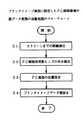
図12は図7の実施形態における書込表示処理のフローチャートである。まずステップS1で、処理対象とするラインを設定するライン番号nをn=1に初期化し、続いてステップS2でラインnのラインデータを読み出す。続いてステップS3で、読出ラインnのラインデータは表示画素を含むか否かチェックする。表示画素を含まない場合にはステップS7にスキップし、このラインの書込表示は行わず、次のライン番号にインクリメントする。
【0079】
表示画素を含んでいる場合にはステップS4に進み、読み出したラインデータを含む他のラインを画像データから検出して選択する。続いてステップS5で、画像データの中から選択ラインの表示画素のデータ消去を行う。そしてステップS6で、液晶パネルに対し選択したライン番号について、現在処理中のラインデータの同時書込みを行う。
【0080】
書込みが済むと、ステップS7でライン番号を1つインクリメントし、ステップS8で最終ラインでなければ、再びステップS3に戻り、次のラインの書込表示を行う。尚、図12の処理にあっては、ステップS6で液晶パネルに検出された書込ラインに対するラインデータの同時書込みを行う前に、表示画素のフレームメモリに対する消去を行っているが、ステップS5,S6が入れ替わっても全く同じである。
【0081】
図13,14は、図7のプロジェクタ装置12側に設けた描画コントローラ46の他の処理形態であり、書込表示を行う表示ラインの順番をラインデータの画素数の少ない順に設定するようにしたことを特徴とする。それ以外の構成及び機能はライン順に処理する実施形態と同じである。
まずフレームメモリ44の表示画像メモリ領域44−1には、図13(A)のような画像データが上位装置としてのパーソナルコンピュータ10側から転送されて格納されている。描画コントローラ46は書込起動信号E0を受けると、まず表示ライン設定部80を起動し、フレームメモリ44の表示画像メモリ領域44−1より順次ラインデータを読み出し、各ラインの画素数をカウントする。
【0082】
図13(A)にあっては、説明を簡単にするため、8ライン×8画素の64画素の表示書込みを例にとっており、この場合、ラインL1〜L8の表示画素数は右側に取り出して示すように、「03455434」となり、これが表示ライン設定部80で検出される。このように表示画素数の検出ができたならば、表示画素数の少ない順番に選択順位を設定する。
【0083】
ここでラインL1は表示画素がないことから、順位設定対象から除外される。そして残りのラインL2〜L8について、選択順位がL2,L7,L6,L3,L4,L5,L8の順番に設定される。なお、表示画素数が同じ場合にはライン番号の小さい方を優先させる。
このような書込表示のためのライン選択順位の設定が済むと、選択順位に従って図13(B)(C)及び図14(D)(E)に示す書込表示が行われる。図13(B)は、図14(A)における選択順位1番のラインL2のラインデータの書込表示であり、この場合、同じデータを含むラインL3が検出されて同時書込みを行い、図14(B)のワークメモリ領域44−2のように、ラインL2,L3の表示画素を消去し、次に選択順位2番のラインL7を設定する。
【0084】
図14(C)はラインL7の書込表示であり、ラインL7のラインデータの表示画素を含むラインL4,L5及びL8が検出される。また、この実施形態にあっては、現在処理対象としているラインL7のラインデータ「00111000」につき、既に書込済みのラインL2,L3のオリジナルデータ即ち図11(A)の表示画像メモリ領域44−1に格納されたラインデータと比較し、この場合、ラインL3に現在処理対象となっているラインL7と同じ表示画素を含むことから、書込ラインとして検出する。
【0085】
したがって、ラインL7のラインデータを用いた同時書込みは、ラインL3,L4,L5,L7,L8の5ラインについて同時に行われる。このときラインL3の3番目の画素については、図13(B)の1回目に既に書込済みであることから、重ね書きを行うことになる。この表示書込みが済むと、図13(C)のワークメモリ領域44−2のように表示画素の消去を行い、次の選択順位3番となるラインL6を指定する。
【0086】
図14(D)はラインL6の書込表示であり、この場合、図13(C)のワークメモリ領域44−2の書込済み表示画素の消去済みの画像データについては同じラインデータを含む他のラインは存在しないが、オリジナルとなる図13(A)の画像データを参照すると、ラインL5に同じデータが一部含まれていることが分かる。
【0087】
したがって、この場合にはラインL6とL5が検出され、ラインL6のラインデータを用いた同時書込みを行う。このため、ラインL5については既に書込みが済んでいることから、その一部が重ね書きとなる。この書込みが済むと、図14(D)のワークメモリ領域44−2のように、新規描画を行った表示画素を消去し、次の選択順位4番となるL3ラインを設定する。
【0088】
しかしながら、ラインL3には表示画素がないことから、次の選択順位である5番のラインL4を設定する。ラインL4には表示画素が存在することから、図14(E)の表示書込みを行う。この表示書込みにあっては、ラインL8が検出され、ラインL4のラインデータを用いたラインL1,L8の2ラインの同時書込みとなる。この書込みに伴い、図14(E)のワークメモリ領域44−2の画素消去で全ての表示画素が消去され、書込終了となる。
【0089】
図15は従来の書込表示と画素数の少ない順番に行う本発明による書込表示を対比したタイミングチャートである。図15(A)の従来書込みの8回に対し、図15(B)の画素数の少ない順番の書込みにあっては、その半分の4回で書込表示を終了することができる。
図16は画素数の少ない順番に表示ラインの順番を設定する画像表示制御のフローチャートである。まずステップS1で画像データの各ラインの画素数をカウントし、ステップS2で表示画素数の少ない順にラインを読み出す。続いてステップS3で現在処理中のラインnのラインデータを含むラインを選択して検出し、ステップS4でワークメモリ領域中の画像データの選択ラインからラインnの表示画素のデータを消去した後、ステップS5で、選択した複数ラインに現在処理中のラインデータの同時書込みを行い、これをステップS6で、全ラインを表示するまで繰り返す。
3.プロジェクタ2画面の表示制御
図17は本発明の画像表示システムの他の実施形態であり、この実施形態にあっては、プロジェクタ装置によりスクリーン上にプリンタ印刷相当の高品質となるプリンタイメージ画面と、パーソナルコンピュータの表示画面であるPC画面を同時に表示できるようにしたことを特徴とする。
【0090】
図17において、この画像表示システムは、上位装置としてのパーソナルコンピュータ10と2画面表示機能を備えたプロジェクタ装置100で構成される。プロジェクタ装置100はパーソナルコンピュータ10に対し、プリンタ用の双方向インタフェースケーブル90とディスプレイ用片方向インタフェースケーブル92で接続されている。
【0091】
プロジェクタ装置100は、スクリーン15上に2000×2000画素の合計400万画素の分解能をもつプリンタイメージ画面102と、パーソナルコンピュータ10に設けている液晶ディスプレイ10−1と同じ640×480画素(約30万画素)から1280×1024画素(約100万画素)の画素数をもつPC画面104を同時に表示する。PC画面104はパーソナルコンピュータ10の液晶ディスプレイ10−1上の表示画面がそのまま表示できる。
【0092】
図18は図17の実施形態におけるプロジェクタ装置100による他の表示形態であり、スクリーン15全体に4000000画素の分解能をもつプリンタイメージ画面102を表示し、プリンタイメージ画面102の一部に重ねて300000画素から1000000画素程度の分解能をもつPC画面104を表示している。スクリーン15上におけるプリンタイメージ画面102のサイズは、プロジェクタ装置100における投影倍率を変えることで適宜に調整できる。
【0093】
またPC画面104も同様に、投影倍率を変えることでサイズを変更できるが、基本的にはパーソナルコンピュータ10の液晶ディスプレイ10−1と同サイズの画面であり、したがってサイズ固定の画面であってもよい。もちろん、PC画面104はスクリーン15上の任意の位置に移動することができる。
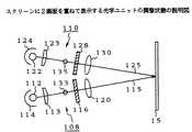
図19は図17のプロジェクタ装置100の実施形態であり、モノクロ画像の投影表示を例にとっている。プロジェクタ装置100には、コントロールユニット106と第1光学ユニット108及び第2光学ユニット110が設けられる。第1光学ユニット108は光源112、ディフレクタ114、集光レンズ116、液晶パネル118及び投影レンズ120で構成され、光軸115によってスクリーン15上に4000000画素の分解能をもつプリンタイメージ画面を表示する。
【0094】
第1光学ユニット108の液晶パネル118は、図2の実施形態のプロジェクタ装置12に設けている液晶パネル52と同じ図6に示した相転移型の液晶パネルである。第2光学ユニットは、光源122、ディフレクタ124、集光レンズ126、液晶パネル128、投影レンズ130で構成され、光軸125の方向となるスクリーン15上にPC画面を投影表示する。
【0095】
第2光学ユニット110の液晶パネル128はTFT型液晶パネルであり、画素数は300000画素から1000000画素程度のものを使用している。第1光学ユニット108及び第2光学ユニット110のそれぞれは、その光軸115,125の方向を上下左右に必要に応じて調整することができる。
図20は図19の光学ユニットの概略であり、プロジェクタ装置に設けている方向操作スイッチに基づいたモータ駆動で光軸方向を調整できるようにしている。まず第1光学ユニット108に対しては、水平旋回モータ132と垂直旋回モータ134が設けられ、操作者による方向調整により、対応するモータを水平回りまたは垂直回りに回動し、光軸115をスクリーン15上の上下左右に調整し、任意の位置にプリンタイメージ画面102を表示することができる。
【0096】
第2光学ユニット110も同様に水平旋回モータ136と垂直旋回モータ138を備え、操作者による方向調整スイッチの操作に応じ、モータ駆動によって第2光学ユニット110を水平回り及び垂直回りに回動し、光軸125をスクリーン15上の任意の位置に向けてPC画面104を表示することができる。
図21は図20の光軸調整の平面概略図であり、第1光学ユニット108及び第2光学ユニット110は軸133,135回りに水平旋回できる。したがって、図20のようにスクリーン15上にプリンタイメージ画面102とPC画面104を並べて表示したい場合には、図示のように両者の光軸115,125を例えば平行状態とすればよい。
【0097】
一方、図18のようにプリンタイメージ画面102の中にPC画面104を重ねて表示したい場合には、図22のように第1光学ユニット108と第2光学ユニット110を軸133,135回りに回動し、光軸115,125がスクリーン15上で例えば一致するように任意の方向に操作すればよい。
なお、図20の調整機構はモータ機構を例にとっているが、操作者による調整ノブの回転操作によって第1光学ユニット108及び第2光学ユニット110の光軸115,125の方向をスクリーン15上の任意の位置に向けるようにしてもよい。
【0098】
図23は図17のプロジェクタ装置100で使用する第1光学ユニット108と第2光学ユニット110の他の実施形態であり、光源を共用したことを特徴とする。即ち、第1光学ユニット108と第2光学ユニット110に対し光源112が共用光源として設けられ、集光レンズ113を介して得られた光源112からの光はハーフミラー190によって第2光学ユニット110に入射し、またハーフミラー190で分岐された光はミラー192により反射された第1光学ユニット108に入射している。
【0099】
スクリーン15に対する光軸115,125の位置を変えるためには、例えば投影レンズ120,130を光軸に直交する方向に移動すればよい。しかし、投影レンズ120,130の移動量が多いと、光軸ずれによりスクリーン15上の画像の歪みが大きくなるため、投影レンズ120,130の移動範囲は、画像の歪みが目立たない範囲に抑える。
【0100】
図24は図17の実施形態におけるパーソナルコンピュータ10及びプロジェクタ装置100の回路構成の実施形態のブロック図である。
パーソナルコンピュータ10は、基本的には図5の実施形態と同じであるが、これに加えてプロジェクタ装置100に対しディスプレイユニット28の表示画像の画像データを転送するアナログ片方向転送機能をもったディスプレイ・インタフェース136を設けており、プロジェクタ装置100をディスプレイインタフェース136にディスプレイ用片方向インタフェースケーブル92を介して接続している。
【0101】
プロジェクタ装置100は図5のディスプレイユニット50を第1液晶ユニット310としており、更に第2液晶ユニット310を新たに設けている。第1液晶ユニット116は、第1液晶パネル52として図6に示した相転移型の2000×2000画素(400万画素)の多画素・高分解能の液晶パネルである。
これに対し第2液晶ユニット320は第2液晶パネル152を備え、第2液晶パネルは例えばTFT型の液晶パネルであり、640×480画素(30万画素)から1280×1024(130万画素)のものを使用しており、パーソナルコンピュータ10のディスプレイユニット28に使用しているTFT液晶パネルと同じ画素数とすることが望ましい。この液晶パネル152に対しては、ライン電極ドライバ154とデータ電極ドライバ156が設けられている。
【0102】
パーソナルコンピュータ10を接続したディスプレイ用インタフェースケーブル92によるPC画面表示のための画像データは、ディスプレイ・インタフェース300で受信され、ディスプレイ・コントローラ140に入力され、第2液晶ユニット320を駆動してPC画面の画像表示を行う。ディスプレイ・コントローラ140は、パーソナルコンピュータ10のディスプレイユニット28に設けているコントローラと同じものが使用される。
【0103】
更にプロジェクタ装置100のMPU36のシステムバス58に対しては、モードスイッチ145が設けられている。モードスイッチ145は次の3つの表示モードを切り換える。
モード1;プリンタイメージ画面とPC画面の同時表示
モード2;プリンタイメージ画面のみの表示
モード3:PC画面のみの表示
具体的には、モードスイッチ145によりモード1を設定すると、描画コントローラ46とディスクプレイ・コントローラ140の両方が動作して第1表示ユニット310の描画によるプリンタイメージ画面の表示と第2液晶ユニット320の描画によるPC画面の表示が行われる。
【0104】
モードスイッチ145によりモード2を設定すると描画コントローラ46が動作し、ディスプレイ・コントローラ140がオフとなり、第1液晶ユニット116によるプリンタイメージ画面のみの表示となる。更にモードスイッチ145でモード3を選択するとディスプレイ・コントローラ140が動作し、描画コントローラ46がオフとなり、第2液晶ユニット302によるPC画面の表示のみとなる。
【0105】
次に図24のプロジェクタ装置100におけるモードスイッチ145でモード1を設定してプリンタイメージ画面とPC画面を同時表示したときの重ね合わせ表示処理を説明する。
図25はスクリーン15上に表示したプリンタイメージ画面102に対するPC画面104の表示例であり、図25(A)はPC画面をプリンタイメージ画面102の左下隅に表示しており、図25(B)はPC画面104をプリンタイメージ画面102の右上隅に表示しており、更に図25(C)はPC画面104を拡大表示させている。
【0106】
このようなスクリーン15上におけるプリンタイメージ画面102に対するPC画面104の表示位置は、基本的にはスクリーン15上でセッティングされる。この場合、位置決めの基準点として例えばプリンタイメージ画面102の左上隅を原点Qとしており、同様にPC画面104についても、その左上隅を原点Pとしている。したがって、プリンタイメージ画面102上におけるPC画面104の位置は、Q点を原点としたプリンタイメージ画面の二次元座標に対するPC画面104の原点Pの座標値で設定することができる。
【0107】
図25(A)〜(C)のようなプリンタイメージ画面102の中に重ねてPC画面104を表示した場合、PC画面104の表示部分についてプリンタイメージ画面102の画像をそのまま表示していると2画像の重ね合わせ表示となり、PC画面104の表示内容が分からなくなる。そこで本発明にあっては、プリンタイメージ画面102に対するPC画面104の表示位置を検出し、フレームメモリ上のプリンタイメージ画面の画像データの中からPC画面の表示領域の画素データを全て黒データに変換する処理を行う。
【0108】
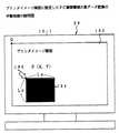
このプリンタイメージ画面の中のPC画面の表示領域の黒データへの変換は、例えば図26のように、パーソナルコンピュータ10の液晶ディスプレイ10−1の画面を使用して行われる。即ち、パーソナルコンピュータ10の液晶ディスプレイ10−1にプロジェクタ装置100で表示させるプリンタイメージ画面162を表示し、オペレータがマウス操作によりカーソル166をプリンタイメージ画面162上のPC画面設定領域164の原点Pにセットする。
【0109】
このときPC画面のサイズLx,Lyが予め決まっていることから、マーカ166によるP点のセットによる変換操作で、斜線のように領域164の画像データが黒データに変換される。このプリンタイメージ画面の画像データからPC画面に対応した領域を黒データに変換するための処理は、図26のパーソナルコンピュータの液晶ディスプレイを使用したオペレータによる指示に基づく手動処理と、プロジェクタ装置100側における第1及び第2光学ユニットの調整状態から得られた制御パラメータに基づく自動処理の二つがある。
【0110】
図27はオペレータの指示に基づく手動処理のフローチャートである。まずステップS1で、図26のように、パーソナルコンピュータ10の液晶ディスプレイ10−1にプロジェクタ装置でスクリーン上に表示するプリンタイメージ画面を縮小して表示する。次にステップS2で、オペレータがマウスによりPC画面を設定する表示したプリンタイメージ画面上の任意の一点を指示すると、その指示点Pのアドレス(x,y)が検出される。
【0111】
続いてステップS3で、指示点P(x,y)を起点として予め定めたPC画面サイズ(Lx,Ly)の範囲184を黒データに変換する。最終的に、黒データに変換されたプリンタイメージ画面をプロジェクタ装置100によりスクリーン上に投影し、投影スクリーン上で黒くなった部分にPC画面が嵌まるように、オペレータがプロジェクタ装置に設けているPC画面用の第2光学ユニット110の向きを調整する。
【0112】
図28はプリンタイメージ画面にPC画面を表示するための領域を黒データに変換する際の自動処理を可能とするプロジェクタ装置100の実施形態である。このPC画面の表示領域を黒データに変換するため、プロジェクタ装置100の第1及び第2光学ユニット108,110のそれぞれは、オートフォーカス機構166,168を備えている。
【0113】
更に第2光学ユニット110にあっては、光軸125の水平回り及び垂直回りの方向を検出する方位センサ170を備えている。PC画面領域のプリンタイメージ画面の画像データを黒データに変換する際には、スクリーン15上に第1光学ユニット108によってプリンタイメージ画面を表示し、この状態で第2光学ユニット110によりPC画面をスクリーン15上に投影表示する。
【0114】
第2光学ユニット110の表示動作を行うと、そのオートフォーカス機構168が動作し、スクリーン15上に光学像を結像するように焦点制御が行われる。このオートフォーカス機構168による自動焦点制御によって、コントロールユニット106の距離検出部172は、スクリーン15までの距離を検出することができる。
【0115】
更に第2光学ユニット110の光軸125をスクリーン15に対し任意に調整し、第1光学ユニット108によって表示しているプリンタイメージ画面の任意の位置にPC画面がくるように光軸115を調整する。この第2光学ユニットのPC画面の位置を決める調整結果は、方位センサ170により水平回り及び垂直回りの方位情報として得られ、コントロールユニット106に設けた方位検出部174がスクリーン15に対する第2光学ユニット110の光軸125の方向を検出する。
【0116】
このようにコントロールユニット106で検出されたスクリーン15までの距離及び光軸125の方位情報は、図23のプロジェクタ装置100からプリンタ用双方向インタフェースケーブル90を介してパーソナルコンピュータ10のMPU14側に転送される。MPU14にあっては、スクリーンに対するPC画面の光軸の方向と距離からプリンタイメージ画面における原点位置P(x,y)を検出し、予め決められたPC画面サイズ(Lx,Ly)の領域を黒データに変換する。
【0117】
更に図25(A)(B)はPC画面104の倍率を1としたい場合であったが、図25(C)のようにPC画面104の倍率を大きくしたい場合には、図28のコントロールユニット106において、第2光学ユニット110の拡大倍率を検出してパーソナルコンピュータ10側に送り、パーソナルコンピュータ10側にあってはPC画面の設定サイズLx,Lyを、検出した倍率により拡大して、拡大した領域を黒データに変換する。
【0118】
図29は、図28のプロジェクタ12側での焦点距離及び光軸方位情報に基づいたPC画面に相当するプリンタイメージ画面の領域の黒データ変換の自動処理のフローチャートである。まずステップS1で、オートフォーカス機構によるPC画面のスクリーンに対する自動焦点制御即ちピント合わせが行われることから、これに基づきスクリーンまでの距離を検出する。
【0119】
続いてステップS2で、オペレータがスクリーン上のPC画面用の投影レンズ即ち第2光学ユニット110の調整による光軸の向きを検出する。ステップS1,S2で検出されたスクリーンまでの距離及びPC画面を投影する第2光学ユニット110の光軸の方位の各情報は、ステップS3でパーソナルコンピュータ10側に転送され、プリンタイメージ画面内におけるPC画面の位置を推定し、ステップS4で、倍率に応じたPC画面表示領域サイズLx,Lyの領域を黒データに変換するデータ黒抜きを行う。
【0120】
もちろん、ステップS4でプリンタイメージデータの黒抜きが済んだならば、黒抜き済みの画像データをプロジェクタ装置12に送ってスクリーン上に表示させ、黒抜き領域に対するPC画面の最終的な位置合わせはオペレータが行えばよい。
尚、図17の実施形態にあっては、図19のように、モノクロ用の第1光学ユニット108と第2光学ユニット110を設けた場合を例にとっているが、図4に示したカラー光学ユニット264と同じ第1カラー光学ユニットと第2カラー光学ユニットを設け、カラープリンタイメージ画面及びカラーPC画面をスクリーン上に表示できるようにしてもよい。
【0121】
また図24の実施形態にあっては、PC画面をスクリーン上に表示する第2液晶ユニット320としてTFT型の液晶パネルを第2液晶パネル152として使用しているが、第1液晶パネル52と同じ相転移型の液晶パネルを使用してもよいことは勿論である。
更に図24の第1液晶ユニット116に設けている相転移型の第1液晶パネル52の書込表示を行う描画コントローラ46としては、図5の描画コントローラ46の場合と全く同様、図7乃至図16に示した高速書込制御を行うことで、1画面当たりの表示時間を大幅に短縮した高速表示を実現することができる。
【0122】
また図17のプリンタイメージ画面102とPC画面104を同時表示できるプロジェクタ100を用いた画像表示システムにあっては、例えばパーソナルコンピュータ10で準備した画像情報を用いたプレゼンテーションの際には、メインとなるプレゼンテーション画像をプリンタイメージ画面102により表示し、補助的なプレゼンテーション情報をPC画面104に表示すればよい。
【0123】
またPC画面104の表示情報としては、メインとなるプリンタイメージ画面102の切換えや説明等に使用する補助的な情報を表示し、説明者はPC画面104を見ながらプリンタイメージ画面102の内容を説明すればよい。もちろん、プリンタイメージ画面102とPC画面104の使い方は、必要に応じて適宜の形態をとることができる。
【0124】
更に上記の実施形態は、パーソナルコンピュータ10に接続される外部装置としてプロジェクタ装置12を例にとるものであったが、本発明はこれに限定されず、パーソナルコンピュータ10からのデータ転送速度を超える表示速度をもつ適宜の表示装置を外部接続した画像表示システムについて、そのまま適用することができる。
【0125】
また上記の実施形態におけるプロジェクタ装置12としては、プロジェクタ装置12に対しスクリーン15を分離して前方に配置したフロントプロジェクタを例にとるものであったが、キャビネットの表示部にレンティキュラスクリーンを配置し、内蔵したディスプレイユニットからの光を投射するリア・プロジェクタであってもよいことは勿論である。
【0126】
【発明の効果】
以上説明してきたように本発明によれば、パーソナルコンピュータに標準装備されている既存のプリンタ用双方向インタフェースをそのまま使用して、圧縮された画像データを外部接続された表示装置例えばプロジェクタ装置に転送することで、インタフェースのデータ転送速度が表示装置の表示速度より低くとも、データ転送速度によって表示速度が遅くなってしまう問題を解消し、効率的な画像データの転送表示が実現できる。
【0127】
更に本発明の画像表示システムにあっては、パーソナルコンピュータに外部接続された例えばプロジェクタ装置によりスクリーン上に独立した2画面を投影表示し、一方の画面はプリンタ用双方向インタフェースを用いた圧縮伝送による多画素・高品質の画面とし、もう一つの画面はパーソナルコンピュータのディスプレイ用片方向インタフェースにより転送した画素数の少ない例えばパーソナルコンピュータ画面そのものとする。
【0128】
これによって、プレゼンテーションの際にメインとなるプリンタイメージ画面に対し補助画面としてPC画面を表示して、プレゼンテーションの説明に必要なガイダンスや画面情報などの補助的な情報をスクリーン上で鮮明に表示することができ、より効率的なプレゼンテーションを行うことができる。
更にプリンタイメージ画面を表示する多画素・高分解能の相転移型液晶パネルの書込表示につき、1回の書込みで同時に複数ラインの書込表示を行うことで、全ラインの書込時間を必要とすることなく、全画素の書込表示を完了でき、相転移型の液晶パネルのネックとなっている表示速度の遅さを解消し、多画素による高分解能と表示速度の向上の両立を図ることができる。
【図面の簡単な説明】
【図1】本発明の原理説明図
【図2】本発明の実施形態の説明図
【図3】モノクロ画像を表示する図2のプロジェクタ装置の説明図
【図4】カラー画像を表示する図2のプロジェクタ装置の説明図
【図5】図2のパーソナルコンピュータとプロジェクタ装置の回路実施形態のブロック図
【図6】図5の相転移型の液晶パネルの概略説明図
【図7】図5の描画コントローラの機能ブロック図
【図8】図7の書込表示の処理内容の説明図
【図9】ライン順に処理する図7の書込表示の処理内容の説明図(続き)
【図10】図7の書込表示の処理内容の説明図(続き)
【図11】図7の書込表示動作の回数を従来と対比したタイミングチャート
【図12】図4の書込表示処理のフローチャート
【図13】画素数の少ないライン順に処理する図7の書込表示の処理内容の説明図
【図14】画素数の少ないライン順に処理する図7の書込表示の処理内容の説明図(続き)
【図15】図13,14の書込表示動作の回数を従来と対比したタイミングチャート
【図16】図13,14の書込表示処理のフローチャート
【図17】スクリーンに2画面を表示する本発明の実施形態の説明図
【図18】図17の他の表示形態の説明図
【図19】図17のプロジェクタ装置の説明図
【図20】プロジェクタ装置に設けた光学ユニットの調整機構の説明図
【図21】スクリーンに2画面を並べて表示する光学ユニットの調整状態の説明図
【図22】スクリーンに2画面を重ねて表示する光学ユニットの調整状態の説明図
【図23】スクリーンに2画面を表示する光学ユニットの他の実施形態の説明図
【図24】図17のパーソナルコンピュータとプロジェクタ装置の回路実施形態のブロック図
【図25】スクリーンのプリンタイメージ画面に対するPC画面の重ね表示の説明図
【図26】プリンタイメージ画面に設定したPC画面領域の黒データ変換の手動処理の説明図
【図27】図26のプリンタイメージ画面に設定したPC画面領域の黒データ変換の手動処理のフローチャート
【図28】プリンタイメージ画面に設定したPC画面領域の黒データ変換の自動処理を実現するプロジェクタ装置の説明図
【図29】プリンタイメージ画面に設定したPC画面領域の黒データ変換の自動処理のフローチャート
【符号の説明】
10:パーソナルコンピュータ
12,100:プロジェクタ装置
14,36:MPU
15:スクリーン
16,38:ROM
17:ドライバモジュール
18:RAM
20,44:フレームメモリ
22:圧縮部
24,40:双方向インタフェース
26,136,138:ディスプレイインタフェース
28:ディスプレイユニット
30,58:システムバス
32,60:データバス
34:プリンタ用双方向インタフェースケーブル
42:復号部
46:描画コントローラ
48,142:ドライブコントローラ
50:ディスプレイユニット
52:液晶パネル(第1液晶パネル)
54,154:ライン電極ドライバ
56,156:データ電極ドライバ
62,162:コントロールユニット
64:光学ユニット
66,112,122,166:光源
68,114,124,168:リフレクタ
70,113,123:集光レンズ
72,120,130:投影レンズ
74−11,74−MN:液晶セル
76:メモリ制御部
78:タイミング制御部
80:表示ライン設定部
82:書込ライン番号検出部
84:フレーム消去部
92:ディスプレイ用片方向インタフェースケーブル
100:プロジェクタ装置
102:プリンタイメージ画面
104:PC画面
108:第1光学ユニット
110:第2光学ユニット
115,125:光軸
116:第1液晶ユニット
128:第2液晶ユニット
132,136:水平旋回モータ
134,138:垂直旋回モータ
140:ディスプレイ・コントローラ
152:第2液晶パネル
164:黒データ変換領域
166,168:オートフォーカス機構
170:方位センサ
200,204,210:反射ミラー
202,206,208,212:ダイクロイックミラー
214:投影レンズ[0001]
BACKGROUND OF THE INVENTION
The present invention relates to an image display system for displaying image by transferring image data converted into bitmap data from a host device such as a personal computer to a display device such as a liquid crystal projector, and in particular, data such as a printer interface. The present invention relates to an image display system that displays an image at high speed using an existing bidirectional interface having a low transfer rate.
[0002]
[Prior art]
Conventionally, as a display device of a personal computer, a CRT display, a liquid crystal display, and the like are often used. These display devices are connected to a display interface of a personal computer, and transfer characters such as analog RGB to display characters and images.
[0003]
In recent years, many image display systems in which a projector device is externally connected to a personal computer for efficient presentation have been put into practical use. In the presentation, a screen based on bitmap data (dot data) such as a document or an image developed in a frame memory of a personal computer is transferred to a projector and the same screen content is projected and displayed on the screen.
[0004]
The projector is usually composed of a light source such as a halogen lamp, a liquid crystal panel, and an optical system such as a mirror and a lens. In the display driving, an image to be displayed on the liquid crystal panel is drawn, and the image is projected on the screen with light transmitted through the light source lamp from the back side and enlarged and displayed. As the liquid crystal panel, an active drive TFT (Thin Film Transistor) liquid crystal panel or the like is used.
[0005]
[Problems to be solved by the invention]
However, currently, the number of pixels that can be displayed on the TFT liquid crystal panel used in the projector is about 640 × 480 pixels to 1280 × 1024 pixels. Therefore, when a document or table on a personal computer screen is enlarged and projected by the projector, the number of pixels is increased. Because there are few, it becomes difficult to read documents and tables.
[0006]
For this reason, images such as documents on personal computers cannot be used as they are in presentations using projectors, and it is necessary to recreate, for example, a document image with a larger character size so that it can be viewed well when enlarged on a projector. was there.
In addition, because current projectors project and display the same screen as the display screen of a personal computer, auxiliary information necessary for screen search and switching cannot be obtained. As a result, during presentations and questions and answers, There was a problem that it was difficult to select and explain the screen.
[0007]
Furthermore, there is only one screen that can be displayed with the current projector, and even if a plurality of screens such as documents and graphs are put on one screen and are simultaneously displayed on the screen, the number of pixels per screen is reduced and the image quality is further improved. In order to maintain the image quality, there is a problem that only the screen is switched and the efficiency of the presentation is poor.
In order to solve such a problem that the number of pixels of the liquid crystal panel of the projector is small, it is conceivable to use, for example, a phase transition type liquid crystal panel that realizes a large number of pixels and a high resolution. A phase transition type liquid crystal panel is suitable for multi-pixel and high definition because it has a simple structure and simple structure compared to a liquid crystal display panel of active matrix drive such as TFT liquid crystal, and is currently suitable for 2500 × 3500 pixels. The above A4 size has been put into practical use.
[0008]
A phase transition type liquid crystal panel has a structure in which transparent line electrodes and data electrodes are arranged in a matrix, and a liquid crystal material is sandwiched between electrodes at the intersection of the two. Further, in order to drive the matrix electrodes with voltage, two driver circuits of a line electrode driver and a data electrode driver are provided. In the display operation of this phase transition type liquid crystal panel, a line electrode displayed by a line electrode driver is selected and a voltage is applied.
[0009]
On the other hand, the data electrode driver applies a voltage corresponding to a pixel to be displayed and a pixel not to be displayed in the pixel data to be written. The liquid crystal of each pixel on the selected line electrode has a cholesteric phase in which incident light is scattered unless a voltage is applied, and displays “black” with low light transmittance. On the other hand, when a voltage is applied, the light transitions to a nematic phase having a high light transmittance, resulting in a transparent “white” display.
[0010]
In this way, display is performed based on the difference in light transmittance, and the same processing is sequentially repeated for all lines, thereby achieving display of the entire screen. Further, the phase transition type liquid crystal panel has a memory function, and the display data once written is displayed as it is by applying a holding voltage.
For details on the phase transition type liquid crystal panel, for example,
Phase transition type projection display (Display and Imaging, 1992, Vol. 1, No. 1, pp. 61-69.)
A5-Mpixel overhead projection display utility a nematic-cholesteric phase-transition liquid crystal. (Journal of the Society for Information Display, Vol. 1, No. 1, 1993. pp43-49.)
It is described in.
[0011]
As described above, the phase transition type liquid crystal panel has a high resolution, a high light transmittance and a bright screen, but has a slow display speed and a slow screen rewriting time as compared with the TFT liquid crystal panel. Yes. That is, it takes tens of milliseconds to rewrite from black (scattering state) to white (transparent state), and conversely, to rewrite from white (transparent state) to black (scattering state), a writing time of several milliseconds is required. Cost. For example, it takes nearly 20 seconds to display an image after initializing a 2500 line × 3500 pixel phase transition type liquid crystal panel.
[0012]
In order to solve the problem of slow screen rewriting time of the phase transition type liquid crystal panel, the conventional display control shortens the rewriting time by constantly comparing the data of the previous screen and the new screen and rewriting only the different parts. (JP-A 61-138991, JP-A-2-217893, JP-A-7-5845, etc.).
However, the conventional display control that rewrites only the different parts of the new screen and the previous screen is effective when switching screens with continuous contents such as movies, but is mainly used for presentations. In the case of a projector that displays still images, the screen content is often completely different each time, and even if only the part that is different from the previous screen is rewritten, the rewriting time cannot be shortened, and this point needs to be improved. Become.
[0013]
Further, when the projector is connected to a personal computer as an external display device and screen data is transferred and displayed, what is used for the interface becomes a problem. The display interface of a personal computer transfers signals such as analog RGB and displays characters and images. However, the display interface is analog and high-speed, but can only transfer in one direction, cannot transfer signals from the display device to the personal computer, and cannot be used for projectors that require bidirectional transfer.
[0014]
As an interface for a personal computer, a parallel interface such as IEEE1284 for connecting a printer device is also known, and this interface is a digital and bidirectional interface and transfers bitmap data. Therefore, it is suitable for transferring image data to the projector.
[0015]
However, when data is sent to the printer, for example, by a Centronics interface known as a printer bidirectional interface, the transfer rate is about 100 Kbytes / second, and 300 dpi A4 monochrome corresponding to multi-pixel display of a phase transition type liquid crystal panel. Since the data is about 1 Mbyte, it takes about 10 seconds to transfer the image data. The printing speed of a printer for a personal computer is, for example, about 4 seconds for an A4 inkjet printer, and the data transfer speed is not a problem.
[0016]
However, a display device such as a projector has a problem that even a phase transition type liquid crystal panel having a low display speed can display one screen in a few seconds, and a bidirectional interface for a printer has a problem that the display speed is limited by the transfer speed. For this reason, a projector cannot be connected using a printer interface provided as a standard in a personal computer, and a dedicated interface having a high transfer speed must be provided separately, which lacks versatility.
[0017]
Further, even if the display speed of the phase transition type liquid crystal panel is improved, the data transfer speed does not catch up with the display speed in the printer interface, and the display speed is limited by the data transfer speed.
An object of the present invention is to provide an image display system capable of transferring image data using an existing printer interface without limiting the display speed of a projector or the like.
[0018]
Another object of the present invention is to use a projector as a display device, transfer a main screen and an auxiliary screen from a personal computer, and display an image on a screen with a high quality display using an individual display panel. Provide a system.
Still another object of the present invention is to provide an image display system that increases the display speed when a phase transition type liquid crystal panel is used in a projector.
[0019]
[Means for Solving the Problems]
FIG. 1 is a diagram illustrating the principle of the present invention. As shown in FIG. 1A, the present invention is an image display system that transfers image data from, for example, a personal computer as the
[0020]
Further, the
The drawing controller includes a display line setting unit that sets an order of display lines to be written and displayed on the display unit, and an image data storage unit for display device according to the order set by the display line setting unit.image Read line dataThe image line data is stored in the line data storage unit as write line data. Reading sectionWhen, In the reading sectionimage Every time line data is read,image Line data and line data storageFor each write stored in Compare with line dataIf the image line data read from the display device image data storage unit includes display pixels that need to be written, the display device image data storage unit Read outimage A write line detector that detects line data as a write display line for the display unit, and a write line detectorAs a writing display line DetectedSimultaneously to all the display lines corresponding to the display line A display driving unit for writing and displaying the image line data read by the reading unit.
Here, for the first and second interfaces, a parallel interface for a printer having a bidirectional transmission function is used. Further, the display unit display speed is higher than the data transfer speed of the first and second interfaces.
[0021]
Thus, in the image data display system of the present invention, image data is compressed and transferred even if the data transfer speed of the interface connecting the host device and the display device is lower than the display speed. Thus, the data transfer speed can be increased, and the image data can be efficiently transferred using the low-speed printer interface without restricting the data display speed.
[0022]
As another form of the present invention, as shown in FIG. 1B, the
[0023]
Correspondingly, the
[0024]
Also in this case, the upper side and display side bidirectional interfaces are parallel interfaces having a bidirectional transfer function for printers, while the transmission interfaces and reception interfaces are display interfaces having a unidirectional transfer function. is there. Furthermore, the display unit has a higher display speed than the data transfer speed between the host interface and the display interface.
[0025]
The display unit of the display device of the present invention is, for example, a projector unit that optically projects and displays a display image on a display panel on a screen. The projector unit includes a first display panel that projects and displays a first image drawn by the drawing controller on a screen, a second display panel that projects and displays a second image drawn by the display controller, and a first on the screen. An adjustment unit for adjusting the display position and display size of the image and the second image is provided.
[0026]
Thereby, two screens can be projected and displayed on the screen of the projector by drawing independent display panels. In this case, the first screen on the screen is the main enlarged display screen used for the presentation, and the auxiliary information such as guidance and screen information necessary for explaining the presentation is contained in the second small screen. Can be displayed clearly.
[0027]
The adjustment unit of the projector is a projection optical unit that can independently adjust the projection positions and magnifications of the first display panel and the second display panel. Specifically, the adjustment unit enlarges and displays the first image of the first display panel on the entire screen, and displays the second image of the second display panel on a part of the screen in a small size. In this case, the display size of the second image is set to the same size as the display screen provided in the host device.
[0028]
In order to make the two-screen overlapping display appropriate, the drawing controller converts the image portion corresponding to the display area of the second image displayed on the first image projected and displayed on the screen into black data and converts the first image into black data. The first image is drawn on the display panel, and the second image is projected and displayed on the missing portion of the image on the screen by the black data drawing of the first image. The first drawing controller converts an area of image data corresponding to a predetermined display size of the second image into black data based on the distance, direction, and magnification from the projector unit to the screen.
[0029]
The projector unit uses a phase transition type liquid crystal panel as the first display panel and the second display panel. The drawing controller includes a display line setting unit that sets the order of display lines to be written and displayed on the liquid crystal display panel, a reading unit that reads line data from the image data storage unit according to the order set by the display line setting unit, and a reading unit. Each time the line data is read, the line data is compared with each line data in the image data storage unit to detect a writing display line for the liquid crystal display panel, and 1 is detected by the display line detecting unit. Alternatively, the line data read by the reading unit is written and displayed on the display lines of the plurality of liquid crystal display panels.
[0030]
By such writing display of the phase transition type liquid crystal panel, writing display of a plurality of lines is simultaneously performed by one writing, and writing writing of all pixels can be completed before writing of all lines. it can. In particular, for image data in which display pixels are arranged in a direction orthogonal to the display line, simultaneous writing with line data common to each line is efficiently performed, and writing display is completed in an extremely short time. For example, in the case of a square or rectangular rectangular image, the writing display of all the pixels is completed only by the writing process of the top line where the display pixels appear.
[0031]
In addition, display by simultaneous writing of a plurality of lines is performed in the order of a large number of display pixels that exist in common for a plurality of lines, and an image appears roughly in the initial stage of writing, and detailed display is performed as time passes. It essentially has a hierarchical display function of switching to. For this reason, in the screen search or the like, the outline of the image can be recognized at the initial stage of writing, and the search by switching the screen can be performed at a considerably high speed.
[0032]
For example, in the case of document image data including ruled lines (vertical ruled lines) orthogonal to the display lines, such as graphs and tables, the vertical ruled lines are displayed in a batch at the initial stage of writing, and this image includes tables and graphs. Can be recognized immediately.
Here, the reading unit includes a display pixel detection unit that detects whether or not the read line data includes a display pixel that needs to be written to the liquid crystal panel. The next display line is read while skipping this section. As a result, line data not including display pixels is excluded from the writing process, and the display speed is improved accordingly.
[0033]
The write line detection unit detects the same display line as the read line data by the reading unit from the image data storage unit. This is equivalent to obtaining the logical product of display pixels of the display line currently being processed and other lines, and the display speed is improved by simultaneously writing the same line data to a plurality of lines.
The write line detection unit detects a display line that partially includes read line data from the read unit from the image data storage unit. This is because the number of pixels to be written at one time is possible by detecting other lines including the display pixels of the display line currently being processed and simultaneously writing the line data of the processing target line to the detected plurality of lines. Increase the display speed as much as possible.
[0034]
The display driver performs additional writing that writes only to pixels that are not written to the liquid crystal panel. In addition, the display portion can also write over the already written pixels.
When all the display pixels of the detected display line have already been written, the write line detection unit excludes this detection line from the write line. Specifically, each time writing is performed, the written display pixels in the image data storage unit may be erased, and the display process may be repeated for display pixels that have not been written.
[0035]
The processing line setting unit specifies the display lines of the display unit in order from the top, and causes the reading unit to read line data. Alternatively, the line data may be read by designating in the order of the small number of display pixels included in the line data. Since the line data with a smaller number of display pixels has more other line data including this, the number of display lines to be written at one time increases, and more efficient writing display can be expected.
[0036]
Furthermore, the present invention provides the projector itself. The projector includes a first display panel that projects and displays a first image drawn by the drawing controller on a screen, a second display panel that projects and displays a second image drawn by the display controller, and a first on the screen. An adjustment unit for adjusting the display position and display size of the image and the second image is provided. In this case as well, the drawing controller converts the image portion corresponding to the display area of the second image displayed on the first image projected and displayed on the screen into black data, and displays the first image on the first display panel. Drawing is performed, and the second image is projected and displayed on the missing portion of the image on the screen by the black data drawing of the first image.
[0037]
DETAILED DESCRIPTION OF THE INVENTION
<Contents>
1. Multi-pixel transfer display with printer interface
2. High-speed display of phase transition type liquid crystal panel
3.
1. Multi-pixel transfer display with printer interface
FIG. 2 is an explanatory diagram of an embodiment of the image display system of the present invention. In FIG. 2, the image display system of the present invention includes a
[0038]
The
[0039]
The
[0040]
FIG. 3 shows an embodiment of the
[0041]
FIG. 4 shows another embodiment of the
[0042]
The
[0043]
Light other than the red component R transmitted through the
[0044]
The light transmitted through the
The red component R image light from the liquid crystal panel 52-1 and the blue component B image light from the liquid crystal panel 52-2 are combined by the dichroic mirror 208. Subsequently, the image light of the green component G reflected by the reflection mirror 210 from the liquid crystal panel 52-3 is synthesized by the dichroic mirror 212, and thereby the synthesized image light of RGB three components is obtained. Finally, the RGB composite image light is incident on the projection lens 214, and a color image is projected and displayed on the
[0045]
FIG. 5 is an embodiment of a circuit configuration of the image display system of FIG. An
[0046]
In the frame memory 20, image data to be output and displayed is expanded and stored as bitmap data (dot data). A compression unit 22 and a high-order
[0047]
As a compression algorithm by the compression unit 22, for example, the same MMR encoding algorithm as that of a facsimile apparatus known as a compression method of bitmap data (dot data) is used. The compression processing by the compression unit 22 may be realized as software by the
[0048]
Further, a
[0049]
The output display of the image on the
[0050]
Subsequently, the bitmap-developed image data is read to the compression unit 22 in units of horizontal line data, for example, and converted into code data by MMR encoding or the like, and is sent to the
Here, in a parallel interface having a bidirectional transfer function for a printer connecting the
[0051]
However, in the image display system of the present invention, the image data of about 1 Mbyte in the frame memory 20 is MMR-encoded by the compression unit 22 and converted into code data. For example, the compression rate is ½. If it can be compressed to about 500 Kbytes, and the display speed of the
[0052]
In actual MMR encoding, the compression rate can be reduced to ½ or less, and if it is image data such as document data, the compression rate is further improved. Image data can be transferred to the
Next, the projector apparatus will be described. The
[0053]
Code data from the
[0054]
The display unit 50 includes a
[0055]
FIG. 6 is a schematic diagram of the
[0056]
The display operation of the phase transition type
[0057]
Each liquid crystal cell on the line electrode selected by the line electrode driver 56 becomes a cholesteric phase in which incident light is scattered unless a voltage is applied by the pixel data “0” on the data electrode driver 56 side. Becomes a low black display. On the other hand, when a voltage is applied from the data electrode driver 56 side corresponding to the pixel data “1”, a transition to a nematic phase having a high light transmittance occurs, and a transparent white display is obtained.
Therefore, an image is displayed as a dot image by changing the transmittance of the liquid crystal cell depending on whether or not the voltage corresponding to 1, 0 of the pixel data by the data electrode driver 56 is applied to the liquid crystal cell of the line electrode selected by the
[0058]
Further, as the writing operation time, it takes tens of seconds to write from black “1” to white “0” by releasing the holding voltage.Retention It takes several milliseconds to write from white “0” to black “1” by applying a voltage. Normally, before writing an image, all the cells of the
[0059]
In order to initialize the
Referring to FIG. 5 again, the
[0060]
Moreover, about 1 Mbyte of data is transferred per screen.The Although this is done using an existing bidirectional parallel interface for printers, the data transfer speed is substantially increased by compressing the image data, and the projector is not limited by the data transfer speed. A high-quality image can be displayed on the
2. High-speed display of phase transition type liquid crystal panel
FIG. 7 shows an embodiment of the drawing controller 46 provided in the
[0061]
The drawing controller 46 includes a timing control unit 78, a display line setting unit 80, a line data storage unit 82, a write line number detection unit 84, and a frame erasing unit 86. The timing control unit 78 receives a write activation signal E0 from the
[0062]
Here, when the drawing controller 46 receives the writing activation signal E0, the drawing controller 46 first performs initialization by erasing the entire surface of the
That is, the
[0063]
A display line setting unit 80 provided in the drawing controller 46 presets the order of writing lines for the
The information on the write lines for which the order is set by the display line setting unit 80 is accessed by the memory control unit 76 every time a timing control signal from the timing control unit 78 is received, and the image corresponding to the set write line. Are read from the work memory area 44-2 of the
[0064]
The write line number detection unit 84 compares the line data sequentially read from the work memory area 44-2 with the line data of the display line that is currently processed and stored in the line data storage unit 82. It is detected whether or not the display pixel of the line data in the storage unit 80, that is, the pixel data of black “1” is included in the line data read out to the write line number detection unit 84. Is detected as the write line number.
[0065]
In the write line number detection unit 84, since the same line data is input and compared to the first line data storage unit 82 when the line data currently being processed is stored, The write line number detection unit 84 also detects the write number for the display line.
Here, when the line data of the write line currently processed is stored in the line data storage unit 82 and the write line number detection unit 84, if the display data is not included in the line data, The timing control unit 78 is notified, and the writing process is not performed for this line, and the process skips to the writing process for the next display line.
[0066]
When the write line number detection unit 84 detects the write line number including the line data currently being processed in the line data storage unit 82, the line data signal E1 and the write line number signal are sent to the drive controller 48. E2 is supplied, and the line data in the line data storage unit 82 is simultaneously written and displayed on the
[0067]
When the line data has been written to the
[0068]
8, FIG. 9 and FIG. 10 are explanatory diagrams of the writing display operation according to the embodiment of FIG. FIG. 8A shows the display image memory area 44-1 of the
[0069]
When the image data in the display image memory area 44-1 in FIG. 8A is written and displayed on the
[0070]
FIG. 8B shows a liquid crystal panel in the writing display of the line L2.52 And the erased state after writing in the work memory area 44-2. First, when the line L2 is set as the display line, the line data “11100000” of the line L2 in the work memory area 44-2 which is the same as the image data in FIG. 8A is read and stored in the line data storage unit 82. At the same time, it is stored in the write line number detector 84, and the first line L2 is detected as the write line.
[0071]
Subsequently, the line data of the next line L3 is read and compared with the line data of the line L2 by the write line number detection unit 84. Since the line L3 includes the display pixel of the line L2, the line L3 is detected as a writing line. The remaining lines L4 to L8 are not detected as write lines because they do not include all the display pixels of the line L2 currently being processed.
[0072]
For this reason, in the writing operation of the line L2 of the
[0073]
Then, after erasing, the next line L3 is set by the display line setting unit 80, and writing display is performed using the line data “00011000” of the line L3 in FIG. Since the display pixels of the line data “00011000” of the line L3 are included in the lines L4 to L8, this line number is detected, and the same line data is simultaneously written to the six lines L3 to L8. Then, the writing pixel is erased as shown in the work memory area 44-2 in FIG. 8C, and the next line L4 is set.
[0074]
FIG. 9D shows a writing display by setting the line L4. In this case, the line L8 is detected in addition to the line L4, and the same line data is written to the two lines L4 and L8, and the display is performed. After the pixel is erased, the next line L5 is set. FIG. 9E shows the writing display of the line L5. In this case, the other lines are not detected and only the line L5 is displayed.
[0075]
Then, after erasing the display pixel, the next line L6 is set. FIG. 9F shows the writing display of the line L6. In this case as well, other lines are not detected and only the line L6 is written and the next line L7 is set after the display pixel is erased. FIG. 10G shows the writing display of the line L7. By this writing, all the display pixels in the work memory area 44-2 are erased, and the writing process is finished.
[0076]
FIG. 11 is a timing chart comparing the conventional writing display and the writing display according to the embodiment of FIG. FIG. 11A shows a conventional writing display, which requires writing display for every eight display lines L1 to L8, that is, eight writing displays. On the other hand, FIG. 11B shows the writing display according to the embodiment of FIG. 4, and the number of writings can be reduced to six by simultaneous writing of a plurality of lines.
[0077]
Further, as the number of times of writing display in the
[0078]
As a result, when searching by screen switching, the contents can be grasped by the general display at the initial stage of the writing display, the required search screen switching judgment can be made quickly, and the target search screen can be obtained. When it is obtained, it can be displayed to the end.
FIG. 12 is a flowchart of the writing display process in the embodiment of FIG. First, in step S1, a line number n for setting a line to be processed is initialized to n = 1, and then line data of the line n is read in step S2. Subsequently, in step S3, it is checked whether or not the line data of the readout line n includes a display pixel. If the display pixel is not included, the process skips to step S7 and does not perform writing display of this line and increments to the next line number.
[0079]
DisplayElementary If it contains, the process proceeds to step S4, and other lines including the read line data are detected from the image data and selected. Subsequently, in step S5, the data of the display pixels on the selected line is erased from the image data. In step S6, the currently processed line data is simultaneously written for the selected line number on the liquid crystal panel.
[0080]
When the writing is completed, the line number is incremented by 1 in step S7, and if it is not the final line in step S8, the process returns to step S3 again to write and display the next line. In the process of FIG. 12, the display pixels are erased from the frame memory before the line data is simultaneously written to the write lines detected on the liquid crystal panel in step S6. The same is true even if S6 is replaced.
[0081]
FIGS. 13 and 14 show other processing forms of the drawing controller 46 provided on the
First, in the display image memory area 44-1 of the
[0082]
In FIG. 13A, in order to simplify the description, display writing of 64 pixels of 8 lines × 8 pixels is taken as an example. In this case, the number of display pixels of the lines L1 to L8 is extracted and shown on the right side. Thus, “03455434” is obtained, and this is detected by the display line setting unit 80. If the number of display pixels can be detected in this way, the selection order is set in ascending order of the number of display pixels.
[0083]
Here, the line L1 is excluded from the rank setting target because there is no display pixel. For the remaining lines L2 to L8, the selection order is set in the order of L2, L7, L6, L3, L4, L5 and L8. When the number of display pixels is the same, the smaller line number is prioritized.
When the line selection order for such writing display is set, the writing display shown in FIGS. 13B, 13C, 14D, and 14E is performed according to the selection order. FIG. 13B is a writing display of the line data of the line L2 of the selection order No. 1 in FIG. 14A. In this case, the line L3 including the same data is detected and simultaneous writing is performed. As in the work memory area 44-2 in (B), the display pixels of the lines L2 and L3 are erased, and then the line L7 of the second selection order is set.
[0084]
FIG. 14C shows the writing display of the line L7, and the lines L4, L5 and L8 including the display pixels of the line data of the line L7 are detected. Further, in this embodiment, for the line data “00111000” of the line L7 that is currently processed, the original data of the lines L2 and L3 already written, that is, the display image memory area 44- of FIG. In this case, the line L3 includes the same display pixel as the line L7 that is currently processed, and is thus detected as a writing line.
[0085]
Accordingly, simultaneous writing using the line data of the line L7 is simultaneously performed on the five lines L3, L4, L5, L7, and L8. At this time, since the third pixel of the line L3 has already been written in the first time in FIG. 13B, it is overwritten. When this display writing is completed, the display pixels are erased as in the work memory area 44-2 in FIG. 13C, and the next line L6 with the third selection order is designated.
[0086]
Figure 14 (D) is a writing display of the line L6. In this case, the erased image data of the written display pixels in the work memory area 44-2 in FIG. Although the line does not exist, it can be seen that a part of the same data is included in the line L5 by referring to the original image data of FIG. 13A.
[0087]
Therefore, in this case, the lines L6 and L5 are detected, and simultaneous writing using the line data of the line L6 is performed. For this reason, since the line L5 has already been written, a part thereof is overwritten. When this writing is completed, the display pixel on which the new drawing has been performed is erased as in the work memory area 44-2 in FIG. 14D, and the L3 line of the
[0088]
However, since there is no display pixel in the line L3, the fifth line L4 which is the next selection order is set. Since there is a display pixel in the line L4, display writing in FIG. In this display writing, the line L8 is detected, and the two lines L1 and L8 are simultaneously written using the line data of the line L4. With this writing, all display pixels are erased by erasing the pixels in the work memory area 44-2 in FIG.
[0089]
FIG. 15 is a timing chart comparing the conventional writing display and the writing display according to the present invention performed in the order of decreasing number of pixels. In the writing in the order of the small number of pixels in FIG. 15B, the writing display can be finished in four times half of the writing in the order of the small number of pixels in FIG.
FIG. 16 is a flowchart of image display control for setting the display line order in ascending order of the number of pixels. First, in step S1, the number of pixels in each line of the image data is counted, and in step S2, the lines are read in ascending order of the number of display pixels. Subsequently, in step S3, a line including line data of the currently processed line n is selected and detected. In step S4, the display pixel data of the line n is deleted from the selected line of image data in the work memory area. In step S5, the line data currently being processed is simultaneously written in the selected plurality of lines, and this is repeated until all lines are displayed in step S6.
3.
FIG. 17 shows another embodiment of the image display system of the present invention. In this embodiment, a projector image screen having a quality equivalent to printer printing on a screen by a projector device and a display screen of a personal computer are shown. It is characterized in that a certain PC screen can be displayed simultaneously.
[0090]
In FIG. 17, this image display system includes a
[0091]
The
[0092]
FIG. 18 shows another display form by the
[0093]
Similarly, the
FIG. 19 shows an embodiment of the
[0094]
The
[0095]
The
FIG. 20 is an outline of the optical unit of FIG. 19, and the optical axis direction can be adjusted by motor drive based on a direction operation switch provided in the projector apparatus. First, a
[0096]
Similarly, the second
FIG. 21 is a schematic plan view of the optical axis adjustment of FIG. 20, in which the first
[0097]
On the other hand, when it is desired to display the
20 is an example of a motor mechanism, but the direction of the
[0098]
FIG. 23 shows another embodiment of the first
[0099]
In order to change the positions of the
[0100]
FIG. 24 is a block diagram of an embodiment of a circuit configuration of the
The
[0101]
The
In contrast, the second liquid crystal unit320 Includes a second liquid crystal panel 152. The second liquid crystal panel is, for example, a TFT-type liquid crystal panel, and ranges from 640 × 480 pixels (300,000 pixels) to 1280 × 1024 (1.3 million The pixel number is preferably the same as that of the TFT liquid crystal panel used in the
[0102]
The image data for displaying the PC screen by the
[0103]
Further, a mode switch 145 is provided for the
Mode 1: Simultaneous display of printer image screen and PC screen
Mode 2: Displaying only the printer image screen
Mode 3: Display only on PC screen
Specifically, when
[0104]
When
[0105]
Next, the overlay display process when
FIG. 25 shows a display example of the
[0106]
The display position of the
[0107]
When the
[0108]
Conversion to black data in the display area of the PC screen in the printer image screen is performed using a screen of the liquid crystal display 10-1 of the
[0109]
At this time, since the sizes Lx and Ly of the PC screen are determined in advance, the image data in the region 164 is converted into black data as shown by diagonal lines by the conversion operation by setting the P point by the
[0110]
FIG. 27 is a flowchart of manual processing based on an operator instruction. First, in step S1, as shown in FIG. 26, the printer image screen displayed on the screen by the projector device is reduced and displayed on the liquid crystal display 10-1 of the
[0111]
Subsequently, in step S3, a range of a predetermined PC screen size (Lx, Ly) starting from the designated point P (x, y).184 Is converted to black data. Finally, the printer image screen converted into black data is projected on the screen by the
[0112]
FIG. 28 shows an embodiment of the
[0113]
Further, the second
[0114]
When the display operation of the second
[0115]
Further, the
[0116]
Thus, the distance to the
[0117]
Further, FIGS. 25A and 25B show the case where the magnification of the
[0118]
FIG. 29 is a flowchart of an automatic process of black data conversion in the area of the printer image screen corresponding to the PC screen based on the focal length and optical axis direction information on the
[0119]
Subsequently, in step S2, the operator detects the direction of the optical axis by adjusting the projection lens for PC screen on the screen, that is, the second
[0120]
Of course, if the printer image data has been blacked out in step S4, the blackened image data is sent to the
In the embodiment of FIG. 17, the case where the monochrome first
[0121]
In the embodiment of FIG. 24, the second liquid crystal unit for displaying the PC screen on the screen.320 Although the TFT type liquid crystal panel is used as the second liquid crystal panel 152, the same phase transition type liquid crystal panel as that of the first
Furthermore, the drawing controller 46 for performing writing display of the phase transition type first
[0122]
In the image display system using the
[0123]
As the display information of the
[0124]
Further, in the above embodiment, the
[0125]
Further, as the
[0126]
【The invention's effect】
As described above, according to the present invention, compressed image data is transferred to an externally connected display device such as a projector device using the existing bidirectional interface for a printer that is provided as a standard in a personal computer as it is. Thus, even if the data transfer speed of the interface is lower than the display speed of the display device, the problem that the display speed is slowed down by the data transfer speed can be solved, and efficient transfer display of image data can be realized.
[0127]
Furthermore, in the image display system of the present invention, two independent screens are projected and displayed on the screen by, for example, a projector device externally connected to a personal computer, and one screen is obtained by compression transmission using a printer bidirectional interface. A multi-pixel, high-quality screen is used, and the other screen is, for example, a personal computer screen itself with a small number of pixels transferred by the one-way display interface of the personal computer.
[0128]
As a result, a PC screen is displayed as an auxiliary screen for the main printer image screen at the time of presentation, and auxiliary information such as guidance and screen information necessary for explaining the presentation is clearly displayed on the screen. Can give a more efficient presentation.
In addition, for multi-pixel, high-resolution phase transition type liquid crystal panels that display printer image screens, multiple lines can be written and displayed at the same time with a single write, thus requiring writing time for all lines. The display and display of all pixels can be completed without the need to eliminate the slow display speed that has become the bottleneck of the phase transition type liquid crystal panel, and both high resolution and high display speed can be achieved with multiple pixels. Can do.
[Brief description of the drawings]
FIG. 1 illustrates the principle of the present invention
FIG. 2 is an explanatory diagram of an embodiment of the present invention.
FIG. 3 is an explanatory diagram of the projector apparatus of FIG. 2 that displays a monochrome image.
4 is an explanatory diagram of the projector apparatus of FIG. 2 that displays a color image.
FIG. 5 is a block diagram of a circuit embodiment of the personal computer and projector device of FIG. 2;
6 is a schematic explanatory diagram of the phase transition type liquid crystal panel of FIG. 5;
7 is a functional block diagram of the drawing controller of FIG.
FIG. 8 is an explanatory diagram of processing contents of the writing display of FIG.
9 is an explanatory diagram of processing contents of the writing display of FIG. 7 processed in line order (continued).
10 is an explanatory diagram of processing details of the writing display of FIG. 7 (continued).
11 is a timing chart in which the number of write display operations in FIG. 7 is compared with the conventional one.
12 is a flowchart of the writing display process of FIG.
13 is an explanatory diagram of processing contents of the writing display of FIG. 7 that are processed in order of lines with a small number of pixels.
FIG. 14 is an explanatory diagram of processing contents of the writing display of FIG.
FIG. 15 is a timing chart in which the number of write display operations in FIGS.
FIG. 16 is a flowchart of the writing display process of FIGS.
FIG. 17 is an explanatory diagram of an embodiment of the present invention that displays two screens on a screen.
18 is an explanatory diagram of another display form of FIG. 17;
FIG. 19 is an explanatory diagram of the projector device of FIG.
FIG. 20 is an explanatory diagram of an optical unit adjustment mechanism provided in the projector apparatus.
FIG. 21 is an explanatory diagram of an adjustment state of an optical unit that displays two screens side by side on a screen;
FIG. 22 is an explanatory diagram of an adjustment state of an optical unit that displays two screens superimposed on a screen.
FIG. 23 is an explanatory diagram of another embodiment of an optical unit that displays two screens on a screen.
24 is a block diagram of a circuit embodiment of the personal computer and projector device of FIG.
FIG. 25 is an explanatory diagram of the overlapping display of the PC screen on the printer image screen of the screen.
FIG. 26 is an explanatory diagram of manual processing for black data conversion in the PC screen area set in the printer image screen.
27 is a flowchart of manual processing for black data conversion in the PC screen area set in the printer image screen of FIG.
FIG. 28 is an explanatory diagram of a projector apparatus that realizes automatic processing for black data conversion of a PC screen area set on a printer image screen.
FIG. 29 is a flowchart of automatic processing for black data conversion in the PC screen area set in the printer image screen.
[Explanation of symbols]
10: Personal computer
12, 100: Projector device
14, 36: MPU
15: Screen
16, 38: ROM
17: Driver module
18: RAM
20, 44: Frame memory
22: Compression unit
24, 40: Bidirectional interface
26, 136, 138: Display interface
28: Display unit
30, 58: System bus
32, 60: Data bus
34: Bidirectional interface cable for printer
42: Decoding unit
46: Drawing controller
48, 142: Drive controller
50: Display unit
52: Liquid crystal panel (first liquid crystal panel)
54,154: Line electrode driver
56, 156: Data electrode driver
62, 162: Control unit
64: Optical unit
66, 112, 122, 166: Light source
68, 114, 124, 168: reflector
70, 113, 123: Condensing lens
72, 120, 130: projection lens
74-11, 74-MN: Liquid crystal cell
76: Memory control unit
78: Timing control unit
80: Display line setting section
82: Write line number detector
84: Frame eraser
92: One-way interface cable for display
100: Projector device
102: Printer image screen
104: PC screen
108: First optical unit
110: Second optical unit
115, 125: optical axis
116: First liquid crystal unit
128: Second liquid crystal unit
132,136: Horizontal turning motor
134,138: Vertical turning motor
140: Display controller
152: Second liquid crystal panel
164: Black data conversion area
166, 168: Autofocus mechanism
170: Direction sensor
200, 204, 210: reflection mirror
202, 206, 208, 212: Dichroic mirror
214: Projection lens
Claims (16)
Translated fromJapanese前記上位装置に、
ビットマップデータに展開された画像データを格納した上位装置用画像データ格納部と、
前記上位装置用画像データ格納部の画像データを読み出して圧縮する圧縮部と、
前記圧縮部で圧縮された画像データを表示装置に転送する上位側双方向インタフェースと、
を設け、
前記表示装置に、
上位装置から転送された圧縮画像データを受信する表示側双方向インタフェースと、
前記上位装置から転送された前記圧縮画像データの復号により元の画像データを復元する復号部と、
前記復号部で復号され表示装置用画像データ格納部に格納された画像データを読み出してディスプレイユニットに表示させる描画コントローラと、
を設け、
該描画コントローラは、
前記ディスプレイユニットに書込表示する表示ラインの順番を設定する表示ライン設定部と、
前記表示ライン設定部で設定された順番に従って、表示装置用画像データ格納部から画像ラインデータを読み出して該画像ラインデータを書込用ラインデータとしてラインデータ格納部に格納する読出部と、
前記読出部で画像ラインデータを読出す毎に、該画像ラインデータと前記ラインデータ格納部に格納した各書込用ラインデータとを比較して前記表示装置用画像データ格納部から読み出された前記画像ラインデータに書き込みを要する表示画素を含んでいる場合は表示装置用画像データ格納部から読み出された画像ラインデータを前記ディスプレイユニットに対する書込表示ラインとして検出する書込ライン検出部と、
前記書込ライン検出部で書込表示ラインであるとして検出した表示ラインに対応するディスプレイの表示ラインの全てへ同時に前記読出部で読み出した画像ラインデータを書き込んで表示させる表示駆動部と、
を備えたことを特徴とする画像表示システム。In an image display system for transferring image data from a host device to a display device for display,
In the host device,
A host device image data storage unit storing image data expanded into bitmap data;
A compression unit that reads and compresses image data in the image data storage unit for the host device;
A high-order bidirectional interface for transferring image data compressed by the compression unit to a display device;
Provided,
In the display device,
A bidirectional interface on the display side for receiving the compressed image data transferred from the host device;
A decoding unit that restores original image data by decoding the compressed image data transferred from the host device;
A drawing controller that reads the image data decoded by the decoding unit and stored in the display device image data storage unit and displays the image data on the display unit;
Provided,
The drawing controller
A display line setting unit for setting the order of display lines to be written and displayed on the display unit;
According to the order set by the display line setting unit,a reading unitfor storing the line data storage unit the image line data as the write line data read out of theimage line data from the display device for image data storageunit,
Image line data for each reading in theprevious SL reading unit,read from the display image data storage unit is compared witheach of the writing linedata stored with theimage line datain the line data storage unitthe image lines whendata are Ndeincluding display pixelsrequired to write to the the write line detecting unit that detects theimage line data readfrom the image data storage unit for a display device as the writing display line for said displayunits ,
A display driving unitfor simultaneously writing and displaying the image line data read by the reading unit onall the display lines of the display corresponding to the display line detectedas the writing display line by thewriting line detection unit;
An image display system comprising:
前記上位装置に、
前記表示装置に転送する第1画像データ及び自己のディスプレイに表示する第2画像データを格納した上位装置用画像データ格納部と、
前記上位装置用画像データ格納部の第1画像データを読み出して圧縮する圧縮部と、
前記圧縮部で圧縮された第1画像データを表示装置に転送する上位側双方向インタフェースと、
上位装置自身のディスプレイに表示する前記上位装置用画像データ格納部の第2画像データを前記表示装置に送信する送信インタフェースと、
を設け、
前記表示装置に、
上位装置から転送された圧縮画像データを受信する表示側双方向インタフェースと、
前記上位装置から転送された前記圧縮画像データの復号により元の第1画像データを復元する復号部と、
前記復号部で復号され表示装置用画像データ格納部に格納された第1画像データを読み出してディスプレイユニットに表示させる描画コントローラと、
前記上位装置から送信された第2画像データを受信する受信インタフェースと、
前記受信インタフェースで受信した第2画像データを前記ディスプレイユニットに表示させるディスプレイ・コントローラと、
を設けたことを特徴とする画像表示システム。In an image display system for transferring image data from a host device to a display device for display,
In the host device,
A host device for the image data storage unit for storing the second image data to be displayedon the first image data and its own Displayb to be transferred to said display device,
A compression unit that reads and compresses the first image data in the image data storage unit for the host device;
A high-order bidirectional interface for transferring the first image data compressed by the compression unit to a display device;
A transmission interface for transmitting the second image data of the image data storage unit for the host device to be displayed on the display of the host device itself to the display device;
Provided,
In the display device,
A bidirectional interface on the display side for receiving the compressed image data transferred from the host device;
A decoding unit that restores the original first image data by decoding the compressed image data transferred from the host device;
A drawing controller for reading the first image data decoded by the decoding unit and stored in the display device image data storage unit and displaying the first image data on the display unit;
A receiving interface for receiving the second image data transmitted from the host device;
A display controller for causing the display unit to display the second image data received by the reception interface;
An image display system characterized by comprising:
前記上位側及び表示側双方向インタフェースは、プリンタ用の双方向転送機能を備えたパラレルインタフェースであり、
前記送信インタフェース及び受信インタフェースは、片方向転送機能を備えたディスプレイ用インタフェースであることを特徴とする画像表示システム。In the image display system according to claim 3,
The upper side and display side bidirectional interfaces are parallel interfaces having a bidirectional transfer function for a printer,
The image display system, wherein the transmission interface and the reception interface are display interfaces having a one-way transfer function.
前記描画コントローラにより描画される第1画像をスクリーンに投影表示する第1表示パネルと、
前記ディスプレイ・コントローラにより描画される第2画像をスクリーンに投影表示する第2表示パネルと、
スクリーン上における前記第1画像と第2画像の表示位置と表示サイズを調整する調整部と、
を備えたことを特徴とする画像表示システム。6. The image display system according to claim 5, wherein the projector unit includes:
A first display panel that projects and displays a first image drawn by the drawing controller on a screen;
A second display panel that projects and displays a second image drawn by the display controller on a screen;
An adjustment unit for adjusting the display position and display size of the first image and the second image on the screen;
An image display system comprising:
前記ディスプレイユニットに書込表示する表示ラインの順番を設定する表示ライン設定部と、
前記表示ライン設定部で設定された順番に従って、表示装置用画像データ格納部から画像ラインデータを読み出して該画像ラインデータを書込用ラインデータとしてラインデータ格納部に格納する読出部と、
前記読出部で画像ラインデータを読出す毎に、該画像ラインデータと前記ラインデータ
格納部に格納した各書込用ラインデータとを比較して前記表示装置用画像データ格納部から読み出された前記画像ラインデータに書き込みを要する表示画素を含んでいる場合は表示装置用画像データ格納部から読み出された画像ラインデータを前記ディスプレイユニットに対する書込表示ラインとして検出する書込ライン検出部と、
前記書込ライン検出部で書込表示ラインであるとして検出した表示ラインに対応するディスプレイの表示ラインの全てへ同時に前記読出部で読み出した画像ラインデータを書き込んで表示させる表示駆動部と、
を備えたことを特徴とする画像表示システム。The image display system according to claim 3, wherein the drawing controller includes:
A display line setting unit for setting the order of display lines to be written and displayed on the display unit;
According to the order set by the display line setting unit,a reading unitfor storing the line data storage unit the image line data as the write line data read out of theimage line data from the display device for image data storageunit,
Image line data for each reading in theprevious SL reading section,read outthe display image data storage unit oral compares therespective the writing linedata stored in the with theimage line data line data storage unit write line detecting unit when are Ndecontains the display pixelsrequired to write to the image line data to detect theimage line data readfrom the image data storage unit for a display device as the writing display line to said display unit When,
A display driving unitfor simultaneously writing and displaying the image line data read by the reading unit onall the display lines of the display corresponding to the display line detectedas the writing display line by thewriting line detection unit;
An image display system comprising:
Priority Applications (5)
| Application Number | Priority Date | Filing Date | Title |
|---|---|---|---|
| JP16888996AJP3631848B2 (en) | 1996-06-28 | 1996-06-28 | Image display system |
| US08/764,276US6046718A (en) | 1996-06-28 | 1996-12-12 | Image display system |
| GB9625992AGB2314750B (en) | 1996-06-28 | 1996-12-13 | Image display system |
| GB9802737AGB2320170B (en) | 1996-06-28 | 1996-12-13 | Optical projector |
| US09/228,975US6195068B1 (en) | 1996-06-28 | 1999-01-12 | Image display system |
Applications Claiming Priority (1)
| Application Number | Priority Date | Filing Date | Title |
|---|---|---|---|
| JP16888996AJP3631848B2 (en) | 1996-06-28 | 1996-06-28 | Image display system |
Publications (2)
| Publication Number | Publication Date |
|---|---|
| JPH1021044A JPH1021044A (en) | 1998-01-23 |
| JP3631848B2true JP3631848B2 (en) | 2005-03-23 |
Family
ID=15876454
Family Applications (1)
| Application Number | Title | Priority Date | Filing Date |
|---|---|---|---|
| JP16888996AExpired - Fee RelatedJP3631848B2 (en) | 1996-06-28 | 1996-06-28 | Image display system |
Country Status (3)
| Country | Link |
|---|---|
| US (2) | US6046718A (en) |
| JP (1) | JP3631848B2 (en) |
| GB (1) | GB2314750B (en) |
Families Citing this family (51)
| Publication number | Priority date | Publication date | Assignee | Title |
|---|---|---|---|---|
| US6996096B2 (en)* | 1997-02-14 | 2006-02-07 | Canon Kabushiki Kaisha | Communication apparatus and a method of controlling a communication apparatus |
| JP2000242408A (en)* | 1998-12-04 | 2000-09-08 | Canon Inc | Coordinate correction device, coordinate correction parameter calculation device, coordinate correction method, coordinate correction parameter calculation method, storage medium storing coordinate correction control program, and storage medium storing coordinate correction parameter calculation program |
| JP2000258723A (en)* | 1999-03-11 | 2000-09-22 | Minolta Co Ltd | Video display device |
| AU4211000A (en)* | 1999-04-08 | 2000-11-14 | New York University | Extremely high resolution foveated display |
| JP3883746B2 (en)* | 1999-07-09 | 2007-02-21 | 三洋電機株式会社 | Presentation device |
| JP3833483B2 (en) | 2001-03-06 | 2006-10-11 | インターナショナル・ビジネス・マシーンズ・コーポレーション | Image display system, image data transmission apparatus, display image data transmission method, differential transfer method, program, and storage medium |
| JP2001075171A (en)* | 1999-09-07 | 2001-03-23 | Minolta Co Ltd | Video dispiay device |
| GB2356542A (en)* | 1999-10-07 | 2001-05-23 | Ibm | Reducing video monitor/cable bandwidth without losing video performance |
| US6661465B2 (en)* | 2000-04-20 | 2003-12-09 | Texas Instruments Incorporated | Television interface for handheld calculator for use with multiple calculator display formats |
| JP2001343929A (en)* | 2000-06-02 | 2001-12-14 | Canon Inc | Image display device |
| US20030067587A1 (en)* | 2000-06-09 | 2003-04-10 | Masami Yamasaki | Multi-projection image display device |
| WO2001096940A1 (en)* | 2000-06-13 | 2001-12-20 | Derryberry Eddie W | Electronic image projection device |
| JP2002055669A (en)* | 2000-08-11 | 2002-02-20 | Nec Viewtechnology Ltd | Connected display device and method of connected displaying |
| JP3661601B2 (en)* | 2001-03-19 | 2005-06-15 | セイコーエプソン株式会社 | Image display by printing instructions |
| US20020171639A1 (en)* | 2001-04-16 | 2002-11-21 | Gal Ben-David | Methods and apparatus for transmitting data over graphic displays |
| US7747655B2 (en)* | 2001-11-19 | 2010-06-29 | Ricoh Co. Ltd. | Printable representations for time-based media |
| US7861169B2 (en)* | 2001-11-19 | 2010-12-28 | Ricoh Co. Ltd. | Multimedia print driver dialog interfaces |
| JP4785320B2 (en)* | 2002-01-31 | 2011-10-05 | キヤノン株式会社 | Storage device |
| GB0211658D0 (en)* | 2002-05-22 | 2002-07-03 | Svanborg Catharina | Novel therapies and methods of screening for therapeutic compounds |
| GB2388942B (en)* | 2002-05-22 | 2005-09-07 | Appliance Studio Ltd | Printing to displays |
| JP4119198B2 (en)* | 2002-08-09 | 2008-07-16 | 株式会社日立製作所 | Image display device and image display module |
| EP1396785A1 (en)* | 2002-09-03 | 2004-03-10 | Nokia Corporation | Display interface and display system |
| US7364313B2 (en)* | 2002-12-27 | 2008-04-29 | Barco N.V. | Multiple image projection system and method for projecting multiple selected images adjacent each other |
| US7928994B2 (en) | 2003-07-16 | 2011-04-19 | Transpacific Image, Llc | Graphics items that extend outside a background perimeter |
| US7274382B2 (en)* | 2003-07-16 | 2007-09-25 | Plut William J | Customizable background sizes and controls for changing background size |
| ES2526613T3 (en)* | 2003-08-19 | 2015-01-13 | Tp Vision Holding B.V. | A visual content signaling device and method for reproducing a visual content signal thereof |
| US7864352B2 (en)* | 2003-09-25 | 2011-01-04 | Ricoh Co. Ltd. | Printer with multimedia server |
| US8077341B2 (en)* | 2003-09-25 | 2011-12-13 | Ricoh Co., Ltd. | Printer with audio or video receiver, recorder, and real-time content-based processing logic |
| JP2005108230A (en)* | 2003-09-25 | 2005-04-21 | Ricoh Co Ltd | Audio / video content recognition / processing function built-in printing system |
| JP4333309B2 (en)* | 2003-09-29 | 2009-09-16 | セイコーエプソン株式会社 | Multi-screen image display system, multi-image display device relative position detection method, multi-image display device relative position detection program, and multi-image display device relative position detection program |
| JP4175234B2 (en)* | 2003-10-07 | 2008-11-05 | セイコーエプソン株式会社 | Display control apparatus, portable information terminal, and display control method |
| JP4513336B2 (en)* | 2004-01-22 | 2010-07-28 | セイコーエプソン株式会社 | Cholesteric liquid crystal driving apparatus and driving method |
| US8274666B2 (en)* | 2004-03-30 | 2012-09-25 | Ricoh Co., Ltd. | Projector/printer for displaying or printing of documents |
| JP2005284195A (en)* | 2004-03-31 | 2005-10-13 | Seiko Epson Corp | Image display system |
| US20060012586A1 (en)* | 2004-07-15 | 2006-01-19 | David Ochs | Display device and method for adjusting display device settings based on a predetermined code |
| WO2007007559A1 (en)* | 2005-07-12 | 2007-01-18 | Nikon Corporation | Projection device with display monitor |
| JP2009518902A (en) | 2005-12-05 | 2009-05-07 | 聯想(北京)有限公司 | Wireless display system and method |
| CN101341479B (en) | 2005-12-12 | 2010-11-10 | 精工爱普生株式会社 | Video docking station for portable media player |
| JP5148505B2 (en)* | 2005-12-14 | 2013-02-20 | ▲聯▼想(北京)有限公司 | Display system and method |
| JP5239136B2 (en)* | 2006-08-22 | 2013-07-17 | セイコーエプソン株式会社 | Data transmission method, data transmission system, information processing apparatus, data transmission program, external apparatus |
| EP2067626B1 (en)* | 2006-09-26 | 2014-08-13 | Nikon Corporation | Printer and printer system |
| CN100423082C (en)* | 2006-11-03 | 2008-10-01 | 北京京东方光电科技有限公司 | Interface unit in a flat panel display system |
| US7746517B2 (en)* | 2007-01-25 | 2010-06-29 | Lexmark International, Inc. | Image illumination and capture in a scanning device |
| JP5577023B2 (en)* | 2008-02-22 | 2014-08-20 | 日立コンシューマエレクトロニクス株式会社 | Display device |
| WO2009154438A1 (en)* | 2008-06-16 | 2009-12-23 | Optelec Development B.V. | Method and apparatus for automatically magnifying a text based image of an object |
| KR101527014B1 (en)* | 2008-12-02 | 2015-06-09 | 엘지전자 주식회사 | Mobile terminal and its display control method |
| US8675019B1 (en)* | 2009-12-03 | 2014-03-18 | Innoventions, Inc. | View navigation guidance system for hand held devices with display |
| KR20120057682A (en)* | 2010-08-06 | 2012-06-07 | 삼성모바일디스플레이주식회사 | Electro phoretic indication display and driving method thereof |
| CN104469343B (en)* | 2014-11-26 | 2017-02-01 | 北京智谷技术服务有限公司 | Optical field display control and device and optical field display device |
| JP6768197B2 (en)* | 2014-12-17 | 2020-10-14 | ソニー株式会社 | Information processing equipment and methods |
| JP2019211595A (en) | 2018-06-04 | 2019-12-12 | 富士ゼロックス株式会社 | Display control unit, program and display system |
Family Cites Families (11)
| Publication number | Priority date | Publication date | Assignee | Title |
|---|---|---|---|---|
| JP2590899B2 (en)* | 1987-07-24 | 1997-03-12 | 松下電器産業株式会社 | Character / graphic information display device |
| JP3080374B2 (en)* | 1989-07-21 | 2000-08-28 | 株式会社日立製作所 | Display device |
| JP2877214B2 (en)* | 1991-02-25 | 1999-03-31 | 日本電信電話株式会社 | Large screen display |
| JPH05173490A (en)* | 1991-12-20 | 1993-07-13 | Mitsubishi Electric Corp | Display device |
| US5577173A (en)* | 1992-07-10 | 1996-11-19 | Microsoft Corporation | System and method of printer banding |
| JP3151770B2 (en)* | 1993-03-26 | 2001-04-03 | キヤノン株式会社 | Compound eye image display |
| GB2284131A (en)* | 1993-11-05 | 1995-05-24 | Hong Kong Productivity Council | Video display apparatus |
| US5617517A (en)* | 1994-09-20 | 1997-04-01 | Seiko Epson Corporation | Two-dimensional method and system for compressing bi-level images |
| US5732202A (en)* | 1995-02-13 | 1998-03-24 | Canon Kabushiki Kaisha | Data processing apparatus, data processing method, memory medium storing data processing program, output device, output control method and memory medium storing control program therefor |
| JPH09123206A (en)* | 1995-10-30 | 1997-05-13 | Towa Kk | Resin molding equipment for electronic parts |
| US5736987A (en)* | 1996-03-19 | 1998-04-07 | Microsoft Corporation | Compression of graphic data normals |
- 1996
- 1996-06-28JPJP16888996Apatent/JP3631848B2/ennot_activeExpired - Fee Related
- 1996-12-12USUS08/764,276patent/US6046718A/ennot_activeExpired - Lifetime
- 1996-12-13GBGB9625992Apatent/GB2314750B/ennot_activeExpired - Fee Related
- 1999
- 1999-01-12USUS09/228,975patent/US6195068B1/ennot_activeExpired - Lifetime
Also Published As
| Publication number | Publication date |
|---|---|
| GB2314750A (en) | 1998-01-07 |
| GB9625992D0 (en) | 1997-01-29 |
| JPH1021044A (en) | 1998-01-23 |
| GB2314750B (en) | 1998-12-09 |
| US6195068B1 (en) | 2001-02-27 |
| US6046718A (en) | 2000-04-04 |
Similar Documents
| Publication | Publication Date | Title |
|---|---|---|
| JP3631848B2 (en) | Image display system | |
| US11625876B2 (en) | Presentation system and display device for use in the presentation system | |
| US9736441B2 (en) | Display image generating device comprising converting function of resolution | |
| US6914616B2 (en) | Image reproduction display apparatus utilizing a controller with selection mask conversion module | |
| JPH08202318A (en) | Display control method of display device having memory and display system thereof | |
| US20090096939A1 (en) | Image transmission apparatus and image display control method in image transmission apparatus | |
| JPH08137620A (en) | Pen input image magnification device | |
| JP3784964B2 (en) | Data projector with document camera | |
| JP5027889B2 (en) | Electronic paper display control apparatus and display control method | |
| JPH07146845A (en) | Information terminal | |
| JP2005208413A (en) | Image processing apparatus and image display apparatus | |
| GB2320170A (en) | Two image computer image projector | |
| JP2008225175A (en) | Projector, program and information storage medium | |
| JP2004252102A (en) | Image display device, image display method, and image display program | |
| JPS61185740A (en) | Projection display device with input device | |
| CN222721520U (en) | Projection apparatus | |
| JP4115879B2 (en) | Image display device | |
| JP5061762B2 (en) | Document camera apparatus, image processing method and program | |
| JP6331561B2 (en) | Image projection device | |
| JPH0836228A (en) | Projection display device | |
| JP2001142419A (en) | Stereoscopic picture display system and data file for stereoscopic picture display | |
| JP2866097B2 (en) | Image recording device | |
| JP5164480B2 (en) | Image display device | |
| JP5488584B2 (en) | Image processing apparatus and program | |
| JPH0593957A (en) | Overhead projector |
Legal Events
| Date | Code | Title | Description |
|---|---|---|---|
| A131 | Notification of reasons for refusal | Free format text:JAPANESE INTERMEDIATE CODE: A131 Effective date:20040706 | |
| A521 | Written amendment | Free format text:JAPANESE INTERMEDIATE CODE: A523 Effective date:20040906 | |
| TRDD | Decision of grant or rejection written | ||
| A01 | Written decision to grant a patent or to grant a registration (utility model) | Free format text:JAPANESE INTERMEDIATE CODE: A01 Effective date:20041207 | |
| A61 | First payment of annual fees (during grant procedure) | Free format text:JAPANESE INTERMEDIATE CODE: A61 Effective date:20041220 | |
| R150 | Certificate of patent or registration of utility model | Free format text:JAPANESE INTERMEDIATE CODE: R150 | |
| FPAY | Renewal fee payment (event date is renewal date of database) | Free format text:PAYMENT UNTIL: 20071224 Year of fee payment:3 | |
| FPAY | Renewal fee payment (event date is renewal date of database) | Free format text:PAYMENT UNTIL: 20081224 Year of fee payment:4 | |
| FPAY | Renewal fee payment (event date is renewal date of database) | Free format text:PAYMENT UNTIL: 20091224 Year of fee payment:5 | |
| FPAY | Renewal fee payment (event date is renewal date of database) | Free format text:PAYMENT UNTIL: 20091224 Year of fee payment:5 | |
| FPAY | Renewal fee payment (event date is renewal date of database) | Free format text:PAYMENT UNTIL: 20101224 Year of fee payment:6 | |
| FPAY | Renewal fee payment (event date is renewal date of database) | Free format text:PAYMENT UNTIL: 20111224 Year of fee payment:7 | |
| FPAY | Renewal fee payment (event date is renewal date of database) | Free format text:PAYMENT UNTIL: 20111224 Year of fee payment:7 | |
| FPAY | Renewal fee payment (event date is renewal date of database) | Free format text:PAYMENT UNTIL: 20121224 Year of fee payment:8 | |
| LAPS | Cancellation because of no payment of annual fees |