JP3631808B2 - Rotor for rotating machine, method for manufacturing the rotor, and magnet unit - Google Patents
Rotor for rotating machine, method for manufacturing the rotor, and magnet unitDownload PDFInfo
- Publication number
- JP3631808B2 JP3631808B2JP15356295AJP15356295AJP3631808B2JP 3631808 B2JP3631808 B2JP 3631808B2JP 15356295 AJP15356295 AJP 15356295AJP 15356295 AJP15356295 AJP 15356295AJP 3631808 B2JP3631808 B2JP 3631808B2
- Authority
- JP
- Japan
- Prior art keywords
- rotor
- pedestal
- permanent magnet
- magnet
- rare earth
- Prior art date
- Legal status (The legal status is an assumption and is not a legal conclusion. Google has not performed a legal analysis and makes no representation as to the accuracy of the status listed.)
- Expired - Fee Related
Links
Images


Landscapes
- Permanent Field Magnets Of Synchronous Machinery (AREA)
Description
Translated fromJapanese【0001】
【産業上の利用分野】
本発明は回転機用ロータ、そのロータの製造方法および磁石ユニットに関する。この回転機にはモータおよびジェネレータが含まれる。
【0002】
【従来の技術】
従来、この種ロータとしては、永久磁石を鋼製ロータ本体に合成樹脂接着剤を用いて接合したものが知られている(例えば、特公昭61−33339号公報参照)。
【0003】
このように合成樹脂接着剤を用いる理由は、永久磁石、特に、希土類元素を含む永久磁石は、非常に脆いため機械加工性が悪く、また高温下に曝されると、金属組織が変化するのでそれに伴い磁気特性が影響を受ける、といった性質を有し、そのため、永久磁石を鋼製ロータ本体に取付ける場合、あり差し構造、ねじ止め、溶接等の取付手段を採用することができないからである。
【0004】
【発明が解決しようとする課題】
しかしながら、合成樹脂接着剤による接合では、回転機の運転に伴いそのロータの温度が上昇し、例えばロータ温度が100℃になると、永久磁石の接合強度が著しく低下する、といった問題がある。このような状況下ではモータの高速回転化の要請に到底対応することはできない。
【0005】
本発明は前記に鑑み、各永久磁石の接合強度が高く、またロータ温度が上昇しても、各永久磁石の接合強度が損われることがなく、しかも各永久磁石の接合構造に対する信頼性の高い前記回転機用ロータを提供することを目的とする。
【0006】
また本発明は前記回転機用ロータの生産性および歩留りを向上させることのできる前記製造方法を提供することを目的とする。
【0007】
さらに本発明は、回転機用ロータの生産性向上に寄与し、またロータ温度の上昇、降下に伴う永久磁石の割れ発生を回避し得る前記磁石ユニットを提供することを目的とする。
【0008】
【課題を解決するための手段】
本発明に係る回転機用ロータは、ロータ本体と、そのロータ本体の外周部に取付けられた複数の磁石ユニットとを備え、各磁石ユニットは、複数の鋼板を積層して構成され前記ロータ本体に取付けられる台座と、その台座に、加熱下で、希土類元素系合金よりなるろう材よりなる接合層を介して接合された希土類元素含有の永久磁石とより構成され、前記台座の少なくとも鋼板積層方向両端部側において、相隣る両鋼板間に、加熱接合により生じた間隙が存することを特徴とする。
【0009】
本発明に係る回転機用ロータの製造方法は、希土類元素を含有する永久磁石と、複数の鋼板を積層してなる台座との間に、希土類元素系合金よりなるろう材を介在させて複数の重ね合せ物を得る第1の工程と、それら重ね合せ物を加熱して、前記永久磁石と台座とを前記ろう材よりなる接合層を介して接合した複数の磁石ユニットを得る第2の工程と、ロータ本体の外周部に、各磁石ユニットをその台座を介して取付ける第3の工程とを用い、各磁石ユニットにおいては、前記台座の少なくとも鋼板積層方向両端部側において、相隣る両鋼板間に、前記第2の工程における加熱接合により生じた間隙が存することを特徴とする。
【0010】
本発明に係る磁石ユニットは、複数の鋼板を積層してなる台座と、その台座に、加熱下で、希土類元素系合金よりなるろう材よりなる接合層を介して接合された希土類元素含有の永久磁石とより構成され、前記台座の少なくとも鋼板積層方向両端部側において、相隣る両鋼板間に、加熱接合により生じた間隙が存することを特徴とする。
【0011】
【作用】
前記ロータにおいて、希土類元素を含有し非常に脆い各永久磁石の接合には、希土類元素系合金よりなる高活性なろう材による接合方式が採用されているので、各永久磁石は、これが希土類元素を含有し非常に脆いものであっても、その接合強度が高く、また回転機の運転に伴いロータ温度が合成樹脂接着剤の接合強度を低下させる温度、例えば100℃に上昇しても、各永久磁石の接合強度が損われることはない。
【0012】
しかも、各磁石ユニットにおいて、台座に対する永久磁石の接合状態を確認した上で、各磁石ユニットのロータ本体への取付けを行うことが可能であるから、ロータにおいて各永久磁石の接合構造に対する信頼性が高い。
【0013】
前記製造方法において、各磁石ユニットの製造に当っては、各台座の熱容量が比較的小さいので、接合に必要な加熱温度までの昇温および加熱接合後の冷却を比較的短時間のうちに行うことが可能であり、これにより接合処理に要する時間が短縮される。
【0014】
またロータ本体への各磁石ユニットの取付けを台座を介して行うので、その取付手段の選択自由度が高く、例えば、あり−あり溝による嵌合、溶接、ねじ止め、かしめ等の手段を採用することが可能であり、前記取付けを容易に行うことができる。
【0015】
これにより、ロータの生産性の向上が図られる。
【0016】
さらに各磁石ユニットの製造に当っては、永久磁石、ろう材および台座よりなる重ね合せ物を加熱する、といった手段を採用するので、各重ね合せ物の加熱状態を均一化して接合不良の発生を極力抑制することができ、これにより磁石ユニット、延いてはロータの歩留りの向上が図られる。
【0017】
例えば、ロータ本体の外周部に複数の永久磁石をろう材を用いて直接的に加熱接合する方式を採用すると、ロータ本体の熱容量が比較的大きいため、接合処理に要する時間が、同一永久磁石数において、磁石ユニットを得る場合の約2倍となり、また1つの永久磁石に割れが生じた場合には、そのロータが不良品となる、といった無駄を生じるが、前記磁石ユニットを製造し、且つ使用すれば、前記問題を回避し得る。
【0018】
前記磁石ユニットにおいて、その磁石ユニットは、台座を介してロータ本体に容易に取付けられるので、ロータの生産性向上に寄与する。
【0019】
また、ロータ温度の上昇、降下に伴い、台座の鋼板積層方向両端部側には熱応力が集中するが、これら両端部側においては相隣る両鋼板間に間隙が存するので、それら鋼板の膨脹、収縮は前記間隙により吸収され、これにより前記両端部側における熱応力を緩和して永久磁石の割れ発生を回避し得る。
【0020】
【実施例】
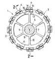
図1,2において、回転機としてのモータ用ロータ1は、複数の円形鋼板2を積層して構成された円筒形ロータ本体3と、そのロータ本体3の外周部に取付けられた複数の磁石ユニット4とを備えている。ロータ本体3の中心に存するスプライン孔5に、ロータ軸6のスプライン軸部7が圧入され、スプライン孔5の両開口縁部はロータ軸6にそれぞれ溶接部8を介して固着される。
【0021】
ロータ本体3は、スプライン孔5を備えたボス部9と、そのボス部9外周面から放射状に延びる複数のアーム部10と、各アーム部10に連設されたリム部11とからなる。リム部11に、その外周面母線方向に延びる複数のあり溝12が形成されている。
【0022】
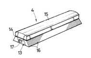
図3に示すように、各磁石ユニット4は断面あり形をなす台座13と、その台座13の短平行辺側の接合面に、加熱下で、ろう材よりなる接合層14を介して接合された永久磁石15とより構成される。
【0023】
各磁石ユニット4は、その台座13をロータ本体3のあり溝12に嵌合させてロータ本体3に取付けられている。
【0024】
ロータ1において、各永久磁石15の接合にはろう材による接合方式が採用されているので、各永久磁石15の接合強度が高く、またモータの運転に伴いロータ温度が合成樹脂接着剤の接合強度を低下させる、例えば100℃に上昇しても、各永久磁石15の接合強度が損なわれることはない。
【0025】
しかも、各磁石ユニット4において、台座13に対する永久磁石15の接合状態を確認した上で、各磁石ユニット4のロータ本体3への取付けを行うことが可能であるから、ロータ1において各永久磁石15の接合構造に対する信頼性が高い。
【0026】
図3に明示するように、台座13は複数のあり形鋼板16を積層して構成され、各鋼板16の接合にはかしめ手段17が採用されている。
【0027】
図4に示すように、台座13において、その少なくとも鋼板積層方向a両端部側、図示例では前記方向aの略全長に亘って、相隣る両鋼板16間に、加熱接合により生じた間隙bが存する。
【0028】
ロータ1において、ロータ温度の上昇、降下に伴い、台座13の鋼板積層方向a両端部側には熱応力が集中する。前記構成によれば、これら両端部側においては相隣る両鋼板16間に間隙bが存するので、それら鋼板16の膨脹、収縮は前記間隙bにより吸収され、これにより前記両端部側における熱応力を緩和して各永久磁石15の割れ発生を回避することができる。
【0029】
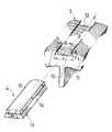
ロータ1の製造に当っては、図5に示すように、永久磁石15の接合面18 と台座13の短平行辺側の接合面19との間に薄板状、箔状等のろう材20を介在させて複数の重ね合せ物21(図7(a)参照)を得る工程と、それら重ね合せ物21を真空加熱炉内に設置し、加熱下で、ろう材20を、例えば液相状態、または固相と液相とが共存する固液共存状態にして永久磁石15と台座13とをろう材20よりなる接合層14を介して接合した複数の磁石ユニット4を得る工程と、図6に示すようにロータ本体3の外周部に存する各あり溝12に、各磁石ユニット4の台座13を嵌合して、各磁石ユニット4をロータ本体3に取付ける工程と、が用いられる。
【0030】
前記製造方法において、各磁石ユニット4の製造に当っては、各台座13の熱容量が比較的小さいので、接合に必要な加熱温度までの昇温および加熱接合後の冷却を比較的短時間のうちに行うことが可能であり、これにより接合処理に要する時間が短縮される。
【0031】
またロータ本体3への各磁石ユニット4の取付けを台座13を介して行うので、その取付手段の選択自由度が高く、前記のようなあり(台座13)−あり溝12による嵌合の外に、溶接、ねじ止め、かしめ等の手段を採用することが可能である。したがって、各磁石ユニット4は、その台座13を介してロータ本体3に容易に取付けられる。
【0032】
これにより、ロータ1の生産性の向上が図られる。なお、あり−あり溝嵌合方式を採用した場合には、必要に応じて、各台座13とロータ本体3とは溶接される。
【0033】
さらに各磁石ユニット4の製造に当っては、永久磁石15、ろう材20および台座13よりなる重ね合せ物21を加熱する、といった手段を採用するので、各重ね合せ物21の加熱状態を均一化して接合不良の発生を極力抑制することができ、これにより磁石ユニット4、延いてはロータ1の歩留りの向上が図られる。
【0034】
次に磁石ユニット4における加熱接合メカニズムを図4,図7により説明する。図7(a)の加熱前においては、重ね合せ物21を形成する永久磁石15と台座13の長さc1は等しい。図7(b)の加熱中においては、永久磁石15および台座13が膨脹し、それらの長さが加熱前よりも長くなり、c2>c1、c3>c1(ただし、c3>c2)となる。冷却後においては、図4に示すように冷却工程で、熱膨脹率が大きい方の台座13における各鋼板16が収縮すると共に永久磁石15に接合されるので、永久磁石15側において相隣る両鋼板16間に間隙bが生じ、その結果、台座13の永久磁石15側は、加熱前の長さc1よりも長い状態に拘束され、c4>c1(例えば、c4≒1.01×c1)となる。
【0035】
これにより、加熱中における台座13の長さc3が、冷却後において加熱前の長さc1に略復元する場合に比べ、接合層14に発生する熱応力が緩和されるので、永久磁石15が脆くても、それに割れが生じる、といった不具合を回避することができる。
【0036】
永久磁石15としては、NdFeB系永久磁石、SmCo系永久磁石等の希土類元素を含むものが用いられる。このような永久磁石15は、接合処理時の加熱温度TがT>650℃になると、その磁気特性、特に、着磁後の保磁力 IHc(磁化の長さI=0)が低下傾向となる。ただし、残留磁束密度Brおよび保磁力 BHc(磁束密度B=0)は殆ど変わらず、したがって最大磁気エネルギ積(BH)maxは略一定である。
【0037】
ろう材20としては、前記のような希土類元素を含む永久磁石15の磁気特性を低下させない加熱温度T、つまりT≦650℃で接合力を発揮するものでなければならない。また、この接合力は、加熱下において、ろう材20が固相状態である場合にはその拡散性により発現し、一方、ろう材20が液相状態または固液共存状態である場合にはその濡れ性により発現することが必要である。
【0038】
このような観点から、ろう材20としては、希土類元素系合金より構成された高活性なものが用いられる。
【0039】
この希土類元素系合金における希土類元素には、Y、La、Ce、Pr、Nd、Sm、Eu、Gd、Tb、Dy、Ho、Er、Tm、YbおよびLuから選択される少なくとも一種が該当し、それらは単体、または混合物であるMm(ミッシュメタル)、Di(ジジミウム)の形態で用いられる。また合金元素AEは希土類元素と共晶反応を行うもので、その合金元素AEには、Cu、Al、Ga、Co、Fe、Ag、Ni、Au、Mn、Zn、Pd、Sn、Sb、Pb、Bi、GeおよびInから選択される少なくとも一種が該当する。合金元素AEの含有量は5原子%≦AE≦50原子%に設定される。二種以上の合金元素AEを含有する場合には、それらの合計含有量が5原子%≦AE≦50原子%となる。ただし、合金元素AEの含有量がAE>50原子%では希土類元素系合金の活性が損われ、一方、AE<5原子%では、固液共存状態において液相を確保することが難しくなる。
【0040】
希土類元素系合金における共晶合金を例示すれば表1の通りである。
【0041】
【表1】
また希土類元素系合金における亜、過共晶合金としては以下のものを挙げることができる。各化学式において、数値の単位は原子%であり、これは以下同じである。
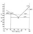
(a) Nd60Cu40合金、Nd75Cu25合金、Nd80Cu20合金、Nd50Cu50合金……液相発生温度520℃(図8参照)
(b) Sm75Cu25合金、Sm65Cu35合金……液相発生温度597℃
(c) Nd90Al10合金(液相発生温度634℃)、Nd80Co20合金(液相発生温度599℃)、La85Ga15合金(液相発生温度550℃)
さらに三元系合金としては、Nd65Fe5Cu30合金(液相発生温度501℃)およびNd70Cu25Al5合金(液相発生温度474℃)を挙げることができる。
【0043】
磁石ユニット4の接合過程における加熱時間hは、それが長過ぎる場合には台座13および永久磁石15の特性に影響を与えるので、h≦10時間であることが望ましく、生産性向上の観点からはh≦1時間である。
【0044】
なお、永久磁石2に対する着磁処理は各磁石ユニット4をロータ本体3に取付けた後行われる。
【0045】
以下、ロータ1の具体的製造例について説明する。
【0046】
ロータ本体3として、図1,6に示すように、厚さ0.4mmの複数の円形冷間圧延鋼板2を積層して構成され、外径が136mm、長さが100mm、あり溝12の数が12個、そのあり溝12の開口幅dがd=22mm、底面幅eがe=30mm、深さfがf=5mm、母線方向の長さgがg=100mmであって、ロータ軸6を備えたものを用意した。
【0047】
台座13として、図5に示すように、厚さ0.4mmのあり形冷間圧延鋼板16を積層して構成され、短平行辺長さhがh=21.8mm、長平行辺長さkがk=29.8mm、高さmがm=4.9mm、長さnがn=100mmであるものを用意した。
【0048】
ろう材20として、Nd70Cu25Al5合金よりなり、縦100mm、横22mm、厚さ0.1mmの箔状ろう材を用意した。
【0049】
永久磁石15として、縦100mm、横22mm、厚さ6mmのNdFeB系永久磁石(住友特殊金属社製、商品名NEOMAX−28UH、キュリー点310℃)を選定した。
【0050】
図5,7(a)に示すように、台座13の上向きの接合面19上に箔状ろう材20を重ね合せ、そのろう材20の上に永久磁石15をその接合面18を下向きにして重ね合せて重ね合せ物21を作製し、同様の手順で合計12個の重ね合せ物21を作製した。その後、全部の重ね合せ物21を真空加熱炉内に設置して、加熱温度T=530℃、加熱時間h=15分間の加熱工程、それに次ぐ炉冷よりなる接合処理を行って、図3に示すように永久磁石15を接合層14を介し台座13に接合した12個の磁石ユニット4を得た。この接合処理においては、加熱温度Tが530℃であって、ろう材20の前記液相発生温度474℃を超えているので、ろう材20は液相状態となる。
【0051】
これらの磁石ユニット4においては、相隣る両鋼板16間の全てに間隙bが存在しており、その間隙bにおける両鋼板16の先端縁間の平均長さb1は約4μmであった。また各磁石ユニット4において永久磁石15に割れの発生はなかった。
【0052】
図6に示すように、ロータ本体3の各あり溝12に各磁石ユニット4の台座13を嵌合してロータ1を得た。
【0053】
ロータ1の耐熱性を調べるため、ロータ1を加熱炉内に設置して150℃で、1時間加熱し、次いで室温下にて冷却したところ、各永久磁石15に割れの発生はなかった。
【0054】
またロータ1においては、それが10000rpm 以上で高速回転してもロータ本体3からの永久磁石15の脱落は皆無であった。
【0055】
さらに、ロータ1の歩留りを調べるため、100個のロータ1に対応すべく1200個の磁石ユニット4を製造したところ、3個の磁石ユニット4において接合不良が発生した。
【0056】
このことから、磁石ユニット4の歩留りRは、R={(1200−3)/1200}×100≒99.8%であり、したがってロータ1の歩留りを大いに向上させ得ることが判明した。
【0057】
【発明の効果】
本発明によれば、ロータにおいて、希土類元素を含有し非常に脆い各永久磁石の接合には、希土類元素系合金よりなる高活性なろう材による接合方式が採用されているので、回転機の運転に伴いロータ温度が上昇しても希土類元素含有の永久磁石の接合強度が損われることがなく、しかも各永久磁石の接合構造に対する信頼性の高い回転機用ロータを提供することができる。
【0058】
また本発明によれば、前記のような特定の手段を採用することによって、回転機用ロータの生産性および歩留りを向上させることが可能な製造方法を提供することができる。
【0059】
さらに本発明によれば、磁石ユニットを前記のように構成することによって、回転機用ロータの生産性向上に寄与することができ、また特に台座を積層鋼板とした上で、その台座の少なくとも鋼板積層方向両端部側において、相隣る両鋼板間に、台座に加熱下で永久磁石をろう材を介して接合(即ち加熱接合)することにより生じた間隙が存するようにしたので、ロータ温度の上昇、降下に伴い台座の鋼板積層方向両端部側に発生する熱応力を緩和して、永久磁石の割れ発生を回避することができる。
【図面の簡単な説明】
【図1】ロータの一例を示す断面図で、図2の1−1線断面図に相当する。
【図2】図1の2−2線断面図である。
【図3】磁石ユニットの斜視図である。
【図4】磁石ユニットの構造を説明する断面図である。
【図5】台座に対する永久磁石およびろう材の重ね合せ方を示す斜視図である。
【図6】ロータ本体に対する磁石ユニットの取付け方を示す斜視図である。
【図7】加熱接合メカニズムを説明するための断面図である。
【図8】Nd−Cu系状態図の要部を示す。
【符号の説明】
1 ロータ
3 ロータ本体
4 磁石ユニット
13 台座
14 接合層
15 永久磁石
16 鋼板
20 ろう材
21 重ね合せ物
a 鋼板積層方向
b 間隙[0001]
[Industrial application fields]
The present invention relates to a rotor for a rotating machine, a method for manufacturing the rotor, and a magnet unit. The rotating machine includes a motor and a generator.
[0002]
[Prior art]
Conventionally, as this type of rotor, a permanent magnet joined to a steel rotor body using a synthetic resin adhesive is known (see, for example, Japanese Patent Publication No. 61-33339).
[0003]
The reason for using a synthetic resin adhesive in this way is that permanent magnets, especially permanent magnets containing rare earth elements, are very brittle and therefore have poor machinability, and the metal structure changes when exposed to high temperatures. This is because the magnetic properties are affected accordingly, and therefore, when a permanent magnet is attached to a steel rotor body, attachment means such as a bayonet structure, screwing, and welding cannot be employed.
[0004]
[Problems to be solved by the invention]
However, the joining with the synthetic resin adhesive has a problem that the temperature of the rotor increases with the operation of the rotating machine. For example, when the rotor temperature reaches 100 ° C., the joining strength of the permanent magnet is remarkably lowered. Under such circumstances, it is impossible to meet the demand for high-speed rotation of the motor.
[0005]
In view of the above, the present invention has a high bonding strength of each permanent magnet, and even if the rotor temperature rises, the bonding strength of each permanent magnet is not impaired, and the bonding structure of each permanent magnet is highly reliable. It is an object of the present invention to provide a rotor for the rotating machine.
[0006]
Another object of the present invention is to provide the manufacturing method capable of improving the productivity and yield of the rotor for a rotating machine.
[0007]
A further object of the present invention is to provide the magnet unit that contributes to improving the productivity of a rotor for a rotating machine and can avoid the occurrence of cracks in a permanent magnet that accompany an increase or decrease in rotor temperature.
[0008]
[Means for Solving the Problems]
A rotor for a rotating machine according to the present invention includes a rotor body and a plurality of magnet units attached to an outer periphery of the rotor body, and each magnet unit is configured by laminating a plurality of steel plates. A pedestal to be attached, and a rare earth element-containing permanent magnet joined to thepedestal via a joining layer made of a brazing material made of a rare earth element alloy under heating, andat least both ends of the pedestal in the steel sheet lamination direction On the part side, a gap formed by heat bonding exists between both adjacent steel plates .
[0009]
In the method for manufacturing a rotor for a rotating machine according to the present invention, a brazing material made of a rare earth element alloy is interposed between a permanent magnet containing a rare earth element and a pedestal formed by laminating a plurality of steel plates. afirst stepof obtaining a superposition thereof, by heating them superposition thereof, asecond stepof obtaining a plurality of magnet units joined through a bonding layer between said permanent magnet and the base made of the brazing material , the outer periphery of the rotor body, each magnet unitwith athird stepof attaching through thepedestal, in each magnet unit, at least the steel plate stacking direction end portion side of the base, a phase Tonariru between the steel plates In addition, there is a gap formed by heat bonding in the second step .
[0010]
A magnet unit according to the present invention includes a pedestal formed by laminating a plurality of steel plates, and arare earth element-containing permanent bonded to the pedestal via a bonding layer made ofa brazing materialmade of arare earth element-based alloy under heating. It is comprised from a magnet, The gap produced by the heat joining exists between both the adjacent steel plates in the steel plate lamination direction both ends side of the said base, It is characterized by the above-mentioned.
[0011]
[Action]
In the rotor, avery brittle permanent magnetcontaining rare earth elements is joinedby a highly active brazing materialmade ofa rare earth alloy, so each permanent magnethas a rare earth element. even very fragile contained, the bonding strength ofthat is high and thetemperature to the rotor temperature with the operation of the rotating machine to lower the bonding strength of the synthetic resin adhesive, for example be increased to 100 ° C., each The bonding strength of the permanent magnet is not impaired.
[0012]
Moreover, in each magnet unit, it is possible to attach each magnet unit to the rotor body after confirming the joining state of the permanent magnet to the pedestal. Therefore, the reliability of the joining structure of each permanent magnet in the rotor is high. high.
[0013]
In the manufacturing method, since the heat capacity of each pedestal is relatively small when manufacturing each magnet unit, the temperature rise to the heating temperature necessary for bonding and the cooling after the heating bonding are performed in a relatively short time. This can reduce the time required for the bonding process.
[0014]
In addition, since each magnet unit is attached to the rotor body via a pedestal, the attachment means can be freely selected. For example, means such as fitting with a dovetail groove, welding, screwing, caulking, etc. are adopted. The attachment can be easily performed.
[0015]
Thereby, the productivity of the rotor is improved.
[0016]
Furthermore, in the production of each magnet unit, means such as heating a superposed product composed of permanent magnets, brazing material and pedestal is adopted, so that the heating state of each superposed product is made uniform to cause poor bonding. As much as possible, the yield of the magnet unit and thus the rotor can be improved.
[0017]
For example, if a method in which a plurality of permanent magnets are directly heat-bonded to the outer periphery of the rotor body using a brazing material is employed, the time required for the bonding process is the same as the number of permanent magnets because the heat capacity of the rotor body is relatively large. In this case, it is about twice as much as when obtaining a magnet unit, and when one permanent magnet is cracked, the rotor becomes a defective product. However, the magnet unit is manufactured and used. Then, the above problem can be avoided.
[0018]
In the magnet unit, the magnet unit can be easily attached to the rotor body via the pedestal, which contributes to an improvement in rotor productivity.
[0019]
As the rotor temperature rises and falls, thermal stress concentrates on both ends of the pedestal in the steel plate lamination direction, but there are gaps between adjacent steel plates on these ends, so the expansion of these steel plates The shrinkage is absorbed by the gap, thereby relieving the thermal stress at the both ends and avoiding the cracking of the permanent magnet.
[0020]
【Example】
1 and 2, a
[0021]
The
[0022]
As shown in FIG. 3, each
[0023]
Each
[0024]
In the
[0025]
Moreover, in each
[0026]
As clearly shown in FIG. 3, the
[0027]
As shown in FIG. 4, in the
[0028]
In the
[0029]
In manufacturing the
[0030]
In the manufacturing method, when each
[0031]
Further, since each
[0032]
Thereby, the productivity of the
[0033]
Further, in manufacturing each
[0034]
Next, the heating and joining mechanism in the
[0035]
Thus, the length c3 of the base 13 during heating, after cooling compared with the case of substantially restoring the length c1 before heating, the heat stress generated in the
[0036]
As the
[0037]
The
[0038]
From such a viewpoint, as the
[0039]
The rare earth element in this rare earth element-based alloy corresponds to at least one selected from Y, La, Ce, Pr, Nd, Sm, Eu, Gd, Tb, Dy, Ho, Er, Tm, Yb and Lu, They are used in the form of a simple substance or a mixture of Mm (Misch metal) and Di (Didimium). The alloy element AE performs a eutectic reaction with a rare earth element. The alloy element AE includes Cu, Al, Ga, Co, Fe, Ag, Ni, Au, Mn, Zn, Pd, Sn, Sb, Pb. At least one selected from Bi, Ge, and In is applicable. The content of the alloy element AE is set to 5 atomic% ≦ AE ≦ 50 atomic%. When two or more kinds of alloy elements AE are contained, the total content thereof is 5 atomic% ≦ AE ≦ 50 atomic%. However, when the content of the alloy element AE is AE> 50 atomic%, the activity of the rare earth element-based alloy is impaired, whereas when AE <5 atomic%, it is difficult to ensure a liquid phase in a solid-liquid coexistence state.
[0040]
Table 1 shows an example of a eutectic alloy in the rare earth element-based alloy.
[0041]
[Table 1]
Examples of the sub- and hypereutectic alloys in the rare earth element-based alloys include the following. In each chemical formula, the unit of the numerical value is atomic%, and so on.
(A) Nd60 Cu40 alloy, Nd75 Cu25 alloy, Nd80 Cu20 alloy, Nd50 Cu50 alloy ... Liquid phase generation temperature 520 ° C. (see FIG. 8)
(B) Sm75 Cu25 alloy, Sm65 Cu35 alloy ... Liquid phase generation temperature 597 ° C
(C) Nd90 Al10 alloy (liquid phase generation temperature 634 ° C.), Nd80 Co20 alloy (liquid phase generation temperature 599 ° C.), La85 Ga15 alloy (liquid phase generation temperature 550 ° C.)
Further, examples of the ternary alloys include Nd65 Fe5 Cu30 alloy (liquid phase generation temperature 501 ° C.) and Nd70 Cu25 Al5 alloy (liquid phase generation temperature 474 ° C.).
[0043]
When the heating time h in the joining process of the
[0044]
The magnetizing process for the
[0045]
Hereinafter, a specific manufacturing example of the
[0046]
As shown in FIGS. 1 and 6, the
[0047]
As shown in FIG. 5, the
[0048]
As the
[0049]
As the
[0050]
As shown in FIGS. 5 and 7 (a), a foil-
[0051]
In these
[0052]
As shown in FIG. 6, a
[0053]
In order to investigate the heat resistance of the
[0054]
In the
[0055]
Furthermore, in order to investigate the yield of the
[0056]
From this, it was found that the yield R of the
[0057]
【The invention's effect】
According to the present invention, in therotor, a highly active brazing material made of a rare earth element-based alloy is used for joining each of the very brittle permanent magnets containing rare earth elements. As a result, even if the rotor temperature rises, the bonding strengthof the rare earth element-containing permanent magnets is not impaired, and a rotor for a rotating machine with high reliability for the bonding structure of each permanent magnet can be provided.
[0058]
Further, according to the present invention, it is possible to provide a manufacturing method capable of improving the productivity and yield of the rotor for a rotating machine by employing the specific means as described above.
[0059]
Further according to the present invention, by configuring the magnet unit as described above, it can contribute to improve productivity of the rotor for a rotating machine, in particularin terms of the pedestal and laminatedsteel, at least the steel plate of the pedestal On both ends of the stacking direction, a gap formed by joining a permanent magnet to the pedestal via a brazing material under heating (that is, heating joining) is present between both adjacent steel plates . It is possible to alleviate the thermal stress generated at both ends of the pedestal in the direction of steel plate lamination as it rises and descends, thereby avoiding the occurrence of cracks inthe permanent magnet.
[Brief description of the drawings]
FIG. 1 is a cross-sectional view showing an example of a rotor, which corresponds to a cross-sectional view taken along line 1-1 of FIG.
FIG. 2 is a sectional view taken along line 2-2 of FIG.
FIG. 3 is a perspective view of a magnet unit.
FIG. 4 is a cross-sectional view illustrating the structure of a magnet unit.
FIG. 5 is a perspective view showing how the permanent magnet and the brazing material are superposed on the pedestal.
FIG. 6 is a perspective view showing how to attach the magnet unit to the rotor body.
FIG. 7 is a cross-sectional view for explaining a heat bonding mechanism.
FIG. 8 shows a main part of an Nd—Cu phase diagram.
[Explanation of symbols]
DESCRIPTION OF
Claims (6)
Translated fromJapanese各磁石ユニット(4)は、複数の鋼板(16)を積層して構成され前記ロータ本体(3)に取付けられる台座(13)と、その台座(13)に、加熱下で、希土類元素系合金よりなるろう材(20)よりなる接合層(14)を介して接合された希土類元素含有の永久磁石(15)とより構成され、
前記台座(13)の少なくとも鋼板積層方向(a)両端部側において、相隣る両鋼板(16)間に、加熱接合により生じた間隙(b)が存することを特徴とする回転機用ロータ。A rotor body (3) and a plurality of magnet units (4) attached to the outer periphery of the rotor body (3);
Each magnet unit (4) includes a pedestal (13) configured by laminating a plurality of steel plates (16) and attached to the rotor body (3), and the pedestal (13) is heated to a rare earth element-based alloy. A rare earth element-containing permanent magnet (15) joined via a joining layer (14) made of a brazing filler metal (20),
A rotor for a rotating machine, whereina gap (b) generated by heat bonding exists between adjacent steel plates (16) at least on both ends of the base plate (13) in the steel plate laminating direction (a) .
それら重ね合せ物(21)を加熱して、前記永久磁石(15)と台座(13)とを前記ろう材(20)よりなる接合層(14)を介して接合した複数の磁石ユニット(4)を得る第2の工程と、
ロータ本体(3)の外周部に、各磁石ユニット(4)をその台座(13)を介して取付ける第3の工程とを用い、
各磁石ユニット(4)においては、前記台座(13)の少なくとも鋼板積層方向(a)両端部側において、相隣る両鋼板(16)間に、前記第2の工程における加熱接合により生じた間隙(b)が存することを特徴とする、回転機用ロータの製造方法。Between a permanent magnet (15) containing a rare earth element and a pedestal (13) formed by laminating a plurality of steel plates (16), a plurality of laps are formed by interposing a brazing material (20) made of a rare earth element alloy. Afirst step of obtaining a combination (21);
The superposed product (21) is heated, and a plurality of magnet units (4) in which the permanent magnet (15) and the base (13) are joined via a joining layer (14) made of the brazing material (20).A second step of obtaining
The outer periphery of the rotor body (3), each magnet unit (4) usingathird step of attaching via its base(13),
In each magnet unit (4), at least at both ends of the pedestal (13) in the steel plate laminating direction (a), a gap formed by heat bonding in the second step between the adjacent steel plates (16). (B) exists , The manufacturing method of the rotor for rotary machines characterized by the above-mentioned.
前記台座(13)の少なくとも鋼板積層方向(a)両端部側において、相隣る両鋼板(16)間に、加熱接合により生じた間隙(b)が存することを特徴とする磁石ユニット。A pedestal (13) formed by laminating a plurality of steel plates (16), and the pedestal (13) are joined via a joining layer (14) made of a brazing material (20) made of a rare earth element-based alloy under heating. A rare earth element-containing permanent magnet (15),
A magnet unit characterized in that there is a gap (b) generated by heat bonding between adjacent steel plates (16) at least on both ends of the pedestal (13) in the steel plate lamination direction (a).
Priority Applications (5)
| Application Number | Priority Date | Filing Date | Title |
|---|---|---|---|
| JP15356295AJP3631808B2 (en) | 1995-06-20 | 1995-06-20 | Rotor for rotating machine, method for manufacturing the rotor, and magnet unit |
| EP95934295AEP0786854B1 (en) | 1994-10-14 | 1995-10-13 | Rotor for rotating machine, method of manufacturing same, and magnet unit |
| DE69510363TDE69510363T2 (en) | 1994-10-14 | 1995-10-13 | ROTOR FOR ROTATING MACHINE, METHOD FOR THE PRODUCTION THEREOF AND MAGNETIC UNIT |
| PCT/JP1995/002102WO1996012336A1 (en) | 1994-10-14 | 1995-10-13 | Rotor for rotating machine, method of manufacturing same, and magnet unit |
| US08/835,672US6081052A (en) | 1994-10-14 | 1997-04-10 | Rotor for rotating machine, process for producing the same, and magnet unit |
Applications Claiming Priority (1)
| Application Number | Priority Date | Filing Date | Title |
|---|---|---|---|
| JP15356295AJP3631808B2 (en) | 1995-06-20 | 1995-06-20 | Rotor for rotating machine, method for manufacturing the rotor, and magnet unit |
Publications (2)
| Publication Number | Publication Date |
|---|---|
| JPH099538A JPH099538A (en) | 1997-01-10 |
| JP3631808B2true JP3631808B2 (en) | 2005-03-23 |
Family
ID=15565216
Family Applications (1)
| Application Number | Title | Priority Date | Filing Date |
|---|---|---|---|
| JP15356295AExpired - Fee RelatedJP3631808B2 (en) | 1994-10-14 | 1995-06-20 | Rotor for rotating machine, method for manufacturing the rotor, and magnet unit |
Country Status (1)
| Country | Link |
|---|---|
| JP (1) | JP3631808B2 (en) |
Families Citing this family (4)
| Publication number | Priority date | Publication date | Assignee | Title |
|---|---|---|---|---|
| JP5308867B2 (en) | 2009-02-26 | 2013-10-09 | 信越化学工業株式会社 | Rotating plate for permanent magnet rotating machine and method for manufacturing permanent magnet rotating machine |
| JP2011058441A (en)* | 2009-09-11 | 2011-03-24 | Jtekt Corp | Electric pump unit |
| US20130038070A1 (en)* | 2010-02-16 | 2013-02-14 | Kurt Andersen | Method for assembling part of a generator, generator and wind turbine |
| JP5893462B2 (en)* | 2012-03-26 | 2016-03-23 | 東芝三菱電機産業システム株式会社 | Rotating electric machine |
- 1995
- 1995-06-20JPJP15356295Apatent/JP3631808B2/ennot_activeExpired - Fee Related
Also Published As
| Publication number | Publication date |
|---|---|
| JPH099538A (en) | 1997-01-10 |
Similar Documents
| Publication | Publication Date | Title |
|---|---|---|
| EP0786854B1 (en) | Rotor for rotating machine, method of manufacturing same, and magnet unit | |
| JP7559101B2 (en) | Method for manufacturing material layers and material layer structures for dynamoelectric rotating machines - Patents.com | |
| US6214480B1 (en) | Article made by joining two members together, and a brazing filler metal | |
| KR100348962B1 (en) | Integral bonded structure of rare earth magnet and metal material and its joining method | |
| US20100072850A1 (en) | Axial gap type rotating machine | |
| JPH08331784A (en) | Permanent magnet field type rotary machine | |
| JPH0638415A (en) | Permanent magnet type rotor | |
| JP3376496B2 (en) | Print motor rotor | |
| JP3631808B2 (en) | Rotor for rotating machine, method for manufacturing the rotor, and magnet unit | |
| JP3599132B2 (en) | Method of manufacturing rotor for rotating machine and permanent magnet fixing device for manufacturing rotor of rotating machine | |
| JP5249897B2 (en) | Iron core manufacturing method | |
| JP3592397B2 (en) | Heat bonding method for two kinds of members having different thermal expansion rates | |
| JP3535256B2 (en) | Rotor for rotating machine and method of manufacturing the same | |
| JPH10201151A (en) | Rotor for electric motor | |
| JP3373950B2 (en) | Heat bonding method of two kinds of members having different thermal expansion coefficients | |
| JPH08141779A (en) | Paste-like bonding material for brazing | |
| JP3802586B2 (en) | Heat joining method using brazing material for two kinds of members with different thermal expansion coefficients | |
| JP3645925B2 (en) | Joined body and joining method of permanent magnet and different kind of member | |
| JP3759198B2 (en) | Joining method of workpieces | |
| JP2003169453A (en) | Rotor device | |
| WO2011120564A1 (en) | Rotor disc, rotor assembly, synchronous machine, and method of producing thereof | |
| JP3759186B2 (en) | Brazing method for joined members | |
| JPH04299039A (en) | Laminated core for compressor motors | |
| KR101098303B1 (en) | Rotor of induction motor and its manufacturing method | |
| JP3631809B2 (en) | Joining method of workpieces |
Legal Events
| Date | Code | Title | Description |
|---|---|---|---|
| A131 | Notification of reasons for refusal | Free format text:JAPANESE INTERMEDIATE CODE: A131 Effective date:20040225 | |
| A521 | Request for written amendment filed | Free format text:JAPANESE INTERMEDIATE CODE: A523 Effective date:20040426 | |
| A02 | Decision of refusal | Free format text:JAPANESE INTERMEDIATE CODE: A02 Effective date:20040804 | |
| A521 | Request for written amendment filed | Free format text:JAPANESE INTERMEDIATE CODE: A523 Effective date:20041004 | |
| A911 | Transfer to examiner for re-examination before appeal (zenchi) | Free format text:JAPANESE INTERMEDIATE CODE: A911 Effective date:20041007 | |
| TRDD | Decision of grant or rejection written | ||
| A01 | Written decision to grant a patent or to grant a registration (utility model) | Free format text:JAPANESE INTERMEDIATE CODE: A01 Effective date:20041201 | |
| A61 | First payment of annual fees (during grant procedure) | Free format text:JAPANESE INTERMEDIATE CODE: A61 Effective date:20041220 | |
| R150 | Certificate of patent or registration of utility model | Free format text:JAPANESE INTERMEDIATE CODE: R150 | |
| FPAY | Renewal fee payment (event date is renewal date of database) | Free format text:PAYMENT UNTIL: 20071224 Year of fee payment:3 | |
| FPAY | Renewal fee payment (event date is renewal date of database) | Free format text:PAYMENT UNTIL: 20081224 Year of fee payment:4 | |
| FPAY | Renewal fee payment (event date is renewal date of database) | Free format text:PAYMENT UNTIL: 20081224 Year of fee payment:4 | |
| FPAY | Renewal fee payment (event date is renewal date of database) | Free format text:PAYMENT UNTIL: 20091224 Year of fee payment:5 | |
| FPAY | Renewal fee payment (event date is renewal date of database) | Free format text:PAYMENT UNTIL: 20091224 Year of fee payment:5 | |
| FPAY | Renewal fee payment (event date is renewal date of database) | Free format text:PAYMENT UNTIL: 20101224 Year of fee payment:6 | |
| LAPS | Cancellation because of no payment of annual fees |