JP3631309B2 - Ink supply device and ink supply method - Google Patents
Ink supply device and ink supply methodDownload PDFInfo
- Publication number
- JP3631309B2 JP3631309B2JP30686995AJP30686995AJP3631309B2JP 3631309 B2JP3631309 B2JP 3631309B2JP 30686995 AJP30686995 AJP 30686995AJP 30686995 AJP30686995 AJP 30686995AJP 3631309 B2JP3631309 B2JP 3631309B2
- Authority
- JP
- Japan
- Prior art keywords
- ink
- print cartridge
- ink reservoir
- pressure
- reservoir
- Prior art date
- Legal status (The legal status is an assumption and is not a legal conclusion. Google has not performed a legal analysis and makes no representation as to the accuracy of the status listed.)
- Expired - Fee Related
Links
- 238000000034methodMethods0.000titleclaimsdescription16
- XLYOFNOQVPJJNP-UHFFFAOYSA-NwaterSubstancesOXLYOFNOQVPJJNP-UHFFFAOYSA-N0.000claimsdescription17
- 239000012530fluidSubstances0.000claimsdescription12
- 238000007789sealingMethods0.000claimsdescription4
- 238000004140cleaningMethods0.000claimsdescription2
- 230000009469supplementationEffects0.000claims1
- 239000000976inkSubstances0.000description170
- 238000004891communicationMethods0.000description7
- 230000009471actionEffects0.000description2
- 239000007788liquidSubstances0.000description2
- 238000007639printingMethods0.000description2
- 229920000742CottonPolymers0.000description1
- 239000004698PolyethyleneSubstances0.000description1
- 239000003086colorantSubstances0.000description1
- 230000008878couplingEffects0.000description1
- 238000010168coupling processMethods0.000description1
- 238000005859coupling reactionMethods0.000description1
- 239000008367deionised waterSubstances0.000description1
- 229910021641deionized waterInorganic materials0.000description1
- 238000006073displacement reactionMethods0.000description1
- 239000000975dyeSubstances0.000description1
- 230000000694effectsEffects0.000description1
- 238000001704evaporationMethods0.000description1
- 238000010438heat treatmentMethods0.000description1
- 229920006267polyester filmPolymers0.000description1
- -1polyethylenePolymers0.000description1
- 229920000573polyethylenePolymers0.000description1
- 229920000642polymerPolymers0.000description1
- 230000008569processEffects0.000description1
- 230000001681protective effectEffects0.000description1
- 230000035939shockEffects0.000description1
- 239000002689soilSubstances0.000description1
- 230000007704transitionEffects0.000description1
Images


Classifications
- B—PERFORMING OPERATIONS; TRANSPORTING
- B41—PRINTING; LINING MACHINES; TYPEWRITERS; STAMPS
- B41J—TYPEWRITERS; SELECTIVE PRINTING MECHANISMS, i.e. MECHANISMS PRINTING OTHERWISE THAN FROM A FORME; CORRECTION OF TYPOGRAPHICAL ERRORS
- B41J2/00—Typewriters or selective printing mechanisms characterised by the printing or marking process for which they are designed
- B41J2/005—Typewriters or selective printing mechanisms characterised by the printing or marking process for which they are designed characterised by bringing liquid or particles selectively into contact with a printing material
- B41J2/01—Ink jet
- B41J2/17—Ink jet characterised by ink handling
- B41J2/175—Ink supply systems ; Circuit parts therefor
- B41J2/17503—Ink cartridges
- B41J2/17506—Refilling of the cartridge
Landscapes
- Ink Jet (AREA)
Description
Translated fromJapanese【0001】
【発明の属する技術分野】
本発明は、一般にコンピュータ制御プリンタに収容されるプリントカートリッジに関するものであり、更に詳細に述べれば、そのようなプリントカートリッジにインクを補給する装置および方法に関する。
【0002】
【技術背景】
プリンタは紙またはポリエステルフィルムのような印刷媒体に文字を印刷する装置であり、普通、画像を印刷命令の形で供給するコンピュータにより制御される。染料またはポリマーである着色剤含有液体を使用するプリンタもある。これら液体を印刷業界では「インク」と言っている。プリンタはインクの適宜なパターンを作り出して画像を永続的に記録するプリントヘッドを使用してインクを媒体に伝えることにより印刷媒体上に画像を形成する。
【0003】
プリンタの一つの形式は精密なドットのパターンを成して印刷媒体に向けて放出されるインクの小さい小滴を形成するインクジェットプリンタである。一定距離から見ると、ドットの集まりは写真の画像が新聞に形成されるのと全く同じように画像を形成する。インクジェットプリンタは高速であり、高品質の印刷を行い、且つ動作中機械的衝撃がないので静かである。
【0004】
典型的には、インクジェットプリンタにはプリントヘッドに配列を成して配置されている多数の個別インクノズルがある。プリントヘッドはキャリッジに支持され、インクノズルは印刷媒体に向き合うが、それから離れて設置されている。キャリッジおよびプリントヘッドはノズルがコンピュータの命令のもとに適時にインクの小滴を放出しながら媒体の表面上を何度も横断する。プリントヘッドの各横断後、印刷媒体は通過に対して横の方向に所定量移動し、その後プリントヘッドを備えたキャリッジがページを再び横断して他のスウォース(Swath)を付着させる。このようにして画像を形成するドットのパターン全体がプリントヘッドにより一度に一スウォースに漸次付着される。
【0005】
熱インクジェットプリンタでは、小滴の放出はノズルに隣接する小体積のインクを加熱し、インクの泡を蒸発させ、それによりインクの小滴をノズルを通して印刷媒体の方に追い出すことにより行なわれる。小滴は媒体に当たり、乾燥して、共に見たとき、永続的に印刷された画像の一スウォースを形成する「ドット」を形成する。
【0006】
プリンタの或る形式では、インクはプリントヘッドと共にキャリッジに取り付けられた溜めに貯蔵されている。インクは毛管作用によりノズルに分配される。これらのプリンタでは、プリントヘッドは、インク溜めが空になったときプリンタに着脱しやすい一回使用の、消費可能な、使い捨てユニットである。このような一つのプリンタおよびそのためのプリントカートリッジは、Hewlett−Packard Journal,February 1994,Volume45,No.1に説明されている。
【0007】
熱インクジェットプリンタの開発の初期の段階では、プリントヘッドの有効寿命は通常、第1のノズルが故障するまでの時間の長さにより決まっていた。更に最近ではノズルおよびプリントヘッドの構成が進歩したので故障までのノズルの寿命がかなり長くなっている。換言すれば、溜めの中の供給インクは現在はノズルの故障が生ずる前に枯渇することがある。したがって、現在、ノズル寿命が延びたためプリントカートリッジに利用できる供給インクの量を更に多くする必要性が存在する。
【0008】
ただし、インク溜めの大きさを単に大きくするだけでは受容可能な解決法が得られなかった。典型的には、溜めはプリンタキャリッジに支持され、プリントヘッドとともに移動する。溜めの大きさが増せば、キャリッジを支持して前後に動かす構造の大きさおよび重量が必然的に増加することになる。これは、キャリッジの質量が増し、またプリンタのコストがかなり増すので、プリンタの性能を損なうことになる。
【0009】
更に他の解決法は空のプリントカートリッジに補充インクを補給することであろうと思われる。これによりプリントヘッドをノズル故障まで何度も使用することができる。今までのところこの方法は、少なくとも四つの重要な問題のため、確実であることまたは満足であることが立証されていない。
【0010】
第1の問題およびオペレータの観点から、おそらく最も重要な問題は、補充インク溜めからインクを、こぼれや漏れを避けながらプリントカートリッジに移す方法である。オペレータはその手、衣服、または作業区域をこぼれたインクで汚したくない。
【0011】
第2の問題は次の動作サイクル中プリントカートリッジの動作圧力を維持することである。通常、プリントカートリッジは大気圧(3.74トール)より水柱で約2インチ低い圧力で動作し、インクは毛管作用によりこの圧力でノズルに供給される。或るプリントカートリッジでは溜めの中のインクの圧力は折畳み式インク袋およびインク袋の壁を大気圧に抗して押しつけるばねにより維持している。インクの圧力が最大レベルを超えれば、インクはノズルから押し出され、プリントカートリッジはインクを紙の上におよびプリンタの中に「たらす」。プリントカートリッジ内のインクの圧力が最小レベルより下に下がると、ノズルへのインクの流れは、毛管圧力が過大となり停止する。
【0012】
第3の問題は補給中プリントカートリッジのインクの圧力を維持することである。インクの圧力が補給中最大レベルを超えると、インクはノズルからたれ、漏れが発生する。プリントカートリッジ内の圧力が最小レベルより下に下がると、空気がノズル内に引き込まれ、これがインクの通路を塞ぎ、ノズル故障を生ずる。
【0013】
第4の問題は補充中空気またはガスがプリントカートリッジに不注意に導入されることである。補充中泡がプリントカートリッジに捕らえられると、これらの泡はプリントカートリッジ内部を走行し、プリントノズルに至る狭い通路を塞いでノズル故障を生ずる可能性がある。
【0014】
【発明の目的】
従前から、プリントカートリッジに補給する多数の方法および装置が存在するが、補給中および次の動作サイクル中こぼれおよび漏れを回避し、プリントカートリッジ内部の圧力を適切に維持する装置の必要性がなお存在することが明らかであり、本発明の目的は、このような要請に応えることにある。
すなわち、本発明の目的は、操作しやすく、使用が簡単で、最初のカートリッジの印刷品位を維持する、プリントカートリッジに補給する装置および方法を提供することにある。
【0015】
【発明の概要】
本発明においては、インク補給装置はオペレータに何時でもプリントカートリッジを「締めくく」らせ、それが空になる前にプリントカートリッジに補給させる。
【0016】
手短に且つ一般的に言えば、本発明による装置はその圧力がプリントカートリッジのインク溜めの圧力より高い補給インク溜め、補給インク溜めに接続され且つプリントカートリッジのインク溜めに接続し得るインク導管、プリントカートリッジのインク溜を開く閉鎖体変移器、プリントカートリッジのインク溜めを閉じる変移閉鎖体位置決め器、および補給インク溜め、インク導管、およびプリントカートリッジのインク溜めを周囲圧力に対して封止し、プリントカートリッジが補給インク溜めの超過圧力により補給できるようにする閉システム、を備えている。
【0017】
本発明のプロセスは補給インク溜めとプリントカートリッジのインク溜めとの間にインク導管で流体連絡を確保すること、補給インク溜め、プリントカートリッジのインク溜め、およびインク導管を周囲圧力から隔離すること、および圧力を等しくしてそれによりインクを補給インク溜めからプリントカートリッジのインク溜めまで移すこと、から構成され、前記補給インク溜めの圧力はプリントカートリッジのインク溜めの圧力より高い。
【0018】
本発明の他の態様および利点は、例を用いて本発明の原理を図解する、付図に関連して行なう下記詳細説明から明らかになるであろう。
【0019】
【実施例】
要約すれば、本発明における装置はそのインク溜め内部に真空があるプリントカートリッジに補給する(すなわち、詰め替えを行う)。補給インク溜めはプリントカートリッジの下に設置され、プリントカートリッジに接続されて周囲圧力から隔離された閉システムを形成している。プリントカートリッジ内の真空は補給インクを引き上げ、その溜めの中に引き込む。装置はプリントカートリッジがその動作レベルまで補給され、その動作背圧まで戻るように垂直に設置されている。
【0020】
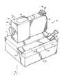
図1を参照すると、参照数字12は全般にプリントカートリッジに補給する装置を示している。装置12は基台14およびインク充填組立体16から構成されている。また図1に示されているのはプリントカートリッジ18である。プリントカートリッジ18にはインク溜め19(図2参照)がある。これは球形の閉鎖体20(図3参照)により封止されている。インク溜め19の初期動作圧力は水柱で約−2から−3インチであり、補給が必要である時の圧力は水柱で約−7から−9インチである。補給が必要なとき、プリントカートリッジ18のインクは空ではなく、真空を維持するのに十分な量のインクが入っていることを認めるべきである。プリントカートリッジ18のこれ以上の説明は上に引用したHewlett−Packard Journalに見いだすことができる。必要な機械的特性を備えていればどんなプリントカートリッジをも使用することができるが、装置12は好適には、アメリカ合衆国、カリフォルニア州、パロアルトのヒューレット・パッカード社から入手できるHewlett−Packard51640および51650型プリントカートリッジに補給するのに使用される。
【0021】
基台14(図1および図2参照)は上ケース22および下ケース24を備えている。上および下のケースは長方形状で、断面が中空であり、共に噛み付き、補給インク27が詰まっているインク袋26を備えている。インク袋26が空になったときそれを取り替えることができるためにケースは分離している。インク袋26は大気圧になっている変形可能な、封止された、ポリエチレン容器である。補給インク27は最初にプリントカートリッジの製造業者から供給されたインクと実質的に同じ品質および形式のものである。インク袋26はインク導管28およびインク袋26を取り替えるための機械的継手30の中で終わっている。導管28は柔軟であり、導管および継手は共にインク溜めを周囲圧力から封止している。
【0022】
図1を参照して、基台14は更にプリントカートリッジ18の動作中生ずるプリントヘッド上の屑(図示せず)の堆積を除去するカートリッジワイパー34を備えている。カートリッジワイパー34はクリップ40により基台に保持されているエラストマー性パッド36および複数のワイパーパッド38を備えている。エラストマー性パッドは拭き取り中プリントヘッドの形状に適合する変形可能な表面となる。ワイパーパッド38は吸収性木綿媒質から作られ、各々脱イオン水で予備加湿されている。各ワイパーパッド38は耐蒸気保護袋に入っているので、水が使用前に蒸発することはない。インク袋26を使用前に開く。
【0023】
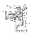
インク充填組立体16(図2参照)は装置を取り囲むハウジング42を備えている。ハウジングにはヒンジ44およびハウジングへの出入ドア45(図1参照)がある。ハウジング42(図2および図3参照)の内部に刳り貫き穴49を有する中空円筒48がある。円筒の遠端はプリントカートリッジ18の補給ポート50およびシール51と係合している。補給ポート50は補給ポート内部の球形閉鎖体20およびシール51により封止されている。中空円筒は更に複数の取り替え閉鎖体54を貯蔵する垂直マガジン53を備えている。マガジン53はマガジンの最上部に設置された着脱可能キャップ55により周囲圧力に対して封止されている。閉鎖体は図2に示すように円筒の割れ目に送り込まれる。中空円筒にはその刳り貫き穴49の中に二つの円形ランド56、56′がある。これら二つのランドは中空円筒への入り口ポート58の両側にある。インク袋26からの導管28は入り口ポートに接続し、インク袋26と中空円筒の刳り貫き穴49との間の流体連絡を確保する。
【0024】
図2を参照して説明する、中空円筒48はプリントカートリッジ18の補給ポート50の中にある球形閉鎖体を変移させたり静置させたりする細長いラム60を受け且つ案内する。ラム60には一方の遠端にハンドル62があるので、ラム60は中空円筒に対して往復運動で前後に移動することができる。ラム60の他方の遠端にはラム60内部に導管64がある。導管は側面ポート66および端部ポート67を通して中空円筒の刳り貫き穴と連絡している。図4に示すように、ラムの側面ポートを中空円筒への入り口ポート58と流体連絡させることができる。また下に説明するようにラムの端部ポートをプリントカートリッジ18のインク溜め19と流体連絡させることができる。ラム60の端部ポート67の端壁に閉鎖体の球形状に適合する凹先端70がある。
【0025】
周囲圧力に対して閉じている封止インク移送システムは補給インク溜め(インク袋)26とプリントカートリッジ18の内部のインク溜め19との間に確定され、維持されていることを認めるべきである。このシステムは中空円筒48のランド56、56′、垂直マガジン53のキャップ55、およびプリントカートリッジ18の補給ポート50の周りのシール51により封止されている。システムは周囲圧力に対して封止されているのでプリントカートリッジ18の閉鎖体20を変移させることができ、プリントカートリッジ18の溜めにインクを補給することができ、取り替え閉鎖体をラム60の前に位置決めして、プリントカートリッジ18内にラム60により静置させることができ、システム内に真空が維持されている間にプリントカートリッジ18をその動作圧力に戻すことができる。他に、取り替え閉鎖体をラムの前面に位置決めする封止可能ローダー72も中空円筒48のランド56、56′、垂直マガジン53のキャップ55、およびプリントカートリッジ18の補給ポート50の周りのシール51により形成されている。
【0026】
更に基台14およびインク充填組立体16は位置決め取り付け具として働くので補給インク溜め(インク袋26)、はプリントカートリッジ18のインク溜め19より所定距離下に設置されていることを認めるべきである。この距離は補給された後のプリントカートリッジ18が水柱約−2から−3インチのその動作圧力に戻るように経験的に決められている。実際に試験した装置の実施例では、この距離は約2から3インチの間にあることがわかった。
【0027】
装置の動作を図3から図6までに示す。図3において、プリントカートリッジ18の補給ポート50のシール51はインク充填組立体16と封止接触している。プリントカートリッジ18のインク溜め19の内部の圧力は水柱で約−7〜−9インチである。この真空は印刷品質の問題を生じてカートリッジ18の補給を必要とするに十分である。上に述べたように、しかし、カートリッジ18のインクは空にならない。インク袋26の圧力は大気圧であるが、インク袋26は周囲圧力に対して封止されている。補給ポート50の最初の球形閉鎖体20はプリントカートリッジ18の側壁の所定位置にあり、インク導管および入り口ポート58はラム60の位置により封止されている。
【0028】
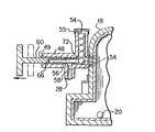
図4において、ラム60のハンドル62はプリントカートリッジ18に向かって中空円筒48に挿入されている。ラム60の遠端の凹先端70は閉鎖体20と係合し、これをインク溜め19の中に変移させている。ラム60の側面ポート66はインク導管28および入り口ポート58と流体連絡している。この運動はインク袋26から、ラム60の導管64を通ってプリントカートリッジ18内部のインク溜め19までのインク流路を開く。インクは、インク袋26(補給溜め)の圧力が大気圧であり、プリントカートリッジ内の圧力より高いので、上向きに流れる。インク流は閉システムの圧力が等しくなるにつれて続き、カートリッジがインクのその動作レベルおよび水柱約−2ないし−3インチのその動作圧力に戻ったとき終わる。補給インク溜め26上方の図2に示すプリントカートリッジ18のインク溜め19の垂直変移は閉インク移送システム内の圧力を下げるのでプリントカートリッジ18は周囲圧力より低い動作圧力まで戻る。
【0029】
インク移送システムが平衡に達し、プリントカートリッジ18がその動作レベルおよび圧力に補給されてから、ラム60は図5に示すようにプリントカートリッジ18から遠くに引き戻される。取り替え閉鎖体54のローダー72は閉システム圧力を維持しながらラム60前面の所定位置に閉鎖体54を落とす。入り口ポート58および導管28は移動ラム60の側面ポート66が中空円筒48の刳り貫き穴49のランド56により封止されるにつれて封止される。
【0030】
次に、ラム60は図6に示すようにプリントカートリッジ18に向かって前方に移動する。この移動により取り替え閉鎖体54はプリントカートリッジ18の側壁の補給ポート50の中に座る。プリントカートリッジ18のインク溜め19はそれにより水柱で約−2と−3インチとの間のその動作圧力で封止される。その後、プリントカートリッジ18は装置から取り外され、補給してから何時でも再使用できる状態になる。
【0031】
本発明の特定の実施例を説明し、図解してきたが、本発明はそのように説明し図解した特定の形態または部分の構成に限定されるものではない。
【0032】
以上述べたように、本発明のインク補給装置は、〔1〕プリントカートリッジが補給前周囲圧力より低い圧力のインク溜めを備えているものにおいて、
a)補給用インクが入っており、その内部の圧力がプリントカートリッジのインク溜めの圧力を超えている補給インク溜め、
b)補給インク溜めに接続され且つプリントカートリッジのインク溜めに接続し得るインク導管、
c)装置に接続されており、プリントカートリッジのインク溜めを開き、補給インク溜めとプリントカートリッジのインク溜めとの間で前記インク導管と流体連絡を確保するための手段、
d)装置に接続されており、プリントカートリッジのインク溜めを閉じる手段、および
e)装置に接続されており、補給インク溜め、インク導管、およびプリントカートリッジのインク溜めを周囲圧力に対して封止し、プリントカートリッジが補給インク溜めの超過圧力により補給されるようにする手段、
から構成されていることを特徴とするもので、〔2〕,〔3〕に記載のような実施態様を包含する。
【0033】
〔2〕更に、補給中補給インク溜めをプリントカートリッジのインク溜めの下方所定距離に位置決めしてプリントカートリッジが補給インク溜めの超過圧力により、周囲圧力より低い動作圧力まで補給されるようにするプリントカートリッジ用位置決め取り付け具を備えている〔1〕に記載の装置。
【0034】
〔3〕補給前のプリントカートリッジのインク溜めの圧力は水柱で約−7インチから−9インチの間にあり、補給インク溜めの圧力はほぼ周囲圧力であり、補給後のプリントカートリッジのインク溜めの圧力は水柱で約−2インチから−3インチの間にある〔1〕に記載の装置。
【0035】
また、本発明のインク補給装置は、〔4〕プリントカートリッジが補給前周囲圧力より低い圧力のインク溜めを備えているものにおいて、
a)補給用インクが入っており、その内部の圧力がプリントカートリッジのインク溜めの圧力を超えている補給インク溜め、
b)補給インク溜めに接続され且つプリントカートリッジのインク溜めに接続し得るインク導管、
c)周囲圧力に対して封止されている間、プリントカートリッジのインク溜めの閉鎖体を変移させて座りなおさせる往復移動可能なラム、
d)取り替え閉鎖体用マガジン、および
e)ラムおよびマガジンに接続され、周囲圧力に対して封止されている間、前記閉鎖体をラムの前に位置決めする封止可能なローダー、
から構成されていることを特徴とし、〔5〕に記載のような実施態様を包含する。
【0036】
〔5〕更に、装置に接続され、補給中プリントカートリッジを掃除する使い捨ての流体入りワイパーを備えている〔4〕に記載の装置。
【0037】
本発明のインク補給方法は、〔6〕プリントカートリッジにインクを補給する方法であって、前記プリントカートリッジは補給前周囲圧力より低い圧力のインク溜めを備えているものにおいて、
a)補給インク溜めとプリントカートリッジのインク溜めとの間にインク導管で流体連絡を確保する工程、
b)補給インク溜め、プリントカートリッジのインク溜め、およびインク導管を周囲圧力から隔離する工程、
c)圧力を等しくし、それによりインクを、その圧力がプリントカートリッジのインク溜めの圧力より高い補給インク溜めからプリントカートリッジのインク溜めに移す工程、
から構成されることを特徴とし、〔7〕〜〔10〕に記載のような実施態様を包含する。
【0038】
〔7〕更に、a)プリントカートリッジのインク溜めに真空を利用して前記圧力を発生させる工程、
b)プリントカートリッジを補給インク溜めの上方に所定距離垂直に変移させることにより前記圧力を下げ、プリントカートリッジが周囲圧力より低い動作圧力まで補給されるようにする工程、
を備えている〔6〕に記載の方法。
【0039】
〔8〕補給前のプリントカートリッジのインク溜めの圧力は水柱で約−7インチから−9インチの間にあり、補給インク溜めの圧力はほぼ周囲圧力であり、補給後のプリントカートリッジのインク溜めの圧力は水柱で約−2インチから−3インチの間にある〔6〕に記載の方法。
【0040】
〔9〕周囲圧力から封止されているインク移送システムを作り且つ保守する工程を備えている〔6〕に記載の方法。
【0041】
〔10〕更に、a)周囲圧力から隔離されている間、プリントカートリッジのインク溜めの閉鎖体を変移させる工程、
b)周囲圧力から隔離されている間、前記インク溜めの取り替え閉鎖体を座りなおさせる工程、
を備えている〔6〕に記載の方法。
【0042】
【発明の効果】
本発明によれば、プリントカートリッジにインクを補給する際に、補給中および次の動作サイクル中こぼれおよび漏れを回避し、プリントカートリッジ内部の圧力を適切に維持することができる。
【図面の簡単な説明】
【図1】本発明による、プリントカートリッジへのインク補給装置の斜視図である。
【図2】図1のインク補給装置の線2−2矢視断面図である。
【図3】図2の一部を拡大して示す断面図であり、プリントカートリッジの補給ポートのシールがインク充填組立体と封止接触している様子を示す図である。
【図4】図2の一部を拡大して示す断面図であり、ラムのハンドルがプリントカートリッジ向かって中空円筒に挿入された様子を示す図である。
【図5】図2の一部を拡大して示す断面図であり、ラムがプリントカートリッジから遠くに引き戻された様子を示す図である。
【図6】図2の一部を拡大して示す断面図であり、ラムがプリントカートリッジに向かって前方に移動した様子を示す図である。
【符号の説明】
12 プリントカートリッジ補給装置
14 基台
16 インク充填組立体
18 プリントカートリッジ
19 インク溜め
20 閉鎖体
22 上ケース
24 下ケース
26 インク袋
27 補給インク
28 インク導管
34 カートリッジワイパー
42 ハウジング
48 中空円筒
50 補給ポート
51 シール
53 閉鎖体マガジン
54 取り替え閉鎖体
56 円形ランド
58 入り口ポート
60 ラム
62 ハンドル
64 導管
66 側面ポート
67 端部ポート
70 ラムの凹先端[0001]
BACKGROUND OF THE INVENTION
The present invention relates generally to print cartridges housed in computer controlled printers and, more particularly, to an apparatus and method for replenishing such print cartridges.
[0002]
[Technical background]
A printer is a device that prints characters on a print medium, such as paper or polyester film, and is usually controlled by a computer that supplies images in the form of print instructions. Some printers use colorant-containing liquids that are dyes or polymers. These liquids are called “inks” in the printing industry. The printer forms an image on the print medium by using a print head that creates an appropriate pattern of ink and permanently records the image to convey the ink to the medium.
[0003]
One type of printer is an inkjet printer that forms a small droplet of ink that is ejected toward a print medium in a precise dot pattern. When viewed from a certain distance, a collection of dots forms an image exactly as a photographic image is formed on a newspaper. Inkjet printers are high speed, perform high quality printing, and are quiet because there is no mechanical shock during operation.
[0004]
Typically, an inkjet printer has a number of individual ink nozzles arranged in an array on the printhead. The print head is supported by the carriage, and the ink nozzles face the print medium but are spaced apart from it. The carriage and printhead traverse the surface of the media many times as the nozzles eject ink droplets in a timely manner under the direction of the computer. After each printhead traversal, the print medium moves a predetermined amount in a direction transverse to the passage, after which the carriage with the printhead traverses the page again to deposit another swath. In this way, the entire pattern of dots forming the image is progressively deposited one swath at a time by the print head.
[0005]
In thermal ink jet printers, droplet ejection is accomplished by heating a small volume of ink adjacent to the nozzle, evaporating the ink bubbles, and thereby expelling the ink droplet through the nozzle toward the print medium. The droplets hit the media and dry to form “dots” that when viewed together form a swath of a permanently printed image.
[0006]
In one type of printer, ink is stored in a reservoir attached to the carriage along with the printhead. Ink is distributed to the nozzles by capillary action. In these printers, the print head is a single use, consumable, disposable unit that is easy to attach and detach to the printer when the ink reservoir is empty. One such printer and print cartridge therefor are described in Hewlett-Packard Journal, February 1994,
[0007]
In the early stages of thermal ink jet printer development, the useful life of the print head was usually determined by the length of time until the first nozzle failed. More recently, advances in nozzle and printhead configurations have significantly increased the life of nozzles until failure. In other words, the supply ink in the reservoir may now be depleted before a nozzle failure occurs. Therefore, there is currently a need to increase the amount of supply ink available to the print cartridge due to the extended nozzle life.
[0008]
However, simply increasing the size of the ink reservoir did not provide an acceptable solution. Typically, the reservoir is supported by the printer carriage and moves with the print head. As the size of the reservoir increases, the size and weight of the structure that supports and moves the carriage back and forth inevitably increases. This increases the carriage mass and significantly increases the cost of the printer, thereby compromising the performance of the printer.
[0009]
Yet another solution would be to refill the empty print cartridge with refill ink. This allows the print head to be used many times until the nozzle fails. So far this method has not proven to be reliable or satisfactory due to at least four important issues.
[0010]
From the first problem and operator perspective, perhaps the most important problem is how to move ink from the refill ink reservoir to the print cartridge while avoiding spills and leaks. The operator does not want to soil his hands, clothes, or work area with spilled ink.
[0011]
The second problem is maintaining the operating pressure of the print cartridge during the next operating cycle. Typically, the print cartridge operates at a pressure of about 2 inches below the atmospheric pressure (3.74 Torr) in the water column and ink is supplied to the nozzles at this pressure by capillary action. In some print cartridges, the pressure of the ink in the reservoir is maintained by a foldable ink bag and a spring that presses against the wall of the ink bag against atmospheric pressure. If the pressure of the ink exceeds the maximum level, the ink is pushed out of the nozzle and the print cartridge “drops” the ink onto the paper and into the printer. When the ink pressure in the print cartridge drops below the minimum level, the ink flow to the nozzle stops due to excessive capillary pressure.
[0012]
The third problem is maintaining the ink pressure of the print cartridge during refilling. If the ink pressure exceeds the maximum level during replenishment, the ink will drip from the nozzle and a leak will occur. As the pressure in the print cartridge drops below a minimum level, air is drawn into the nozzle, which blocks the ink path and causes nozzle failure.
[0013]
A fourth problem is that air or gas is inadvertently introduced into the print cartridge during refilling. If bubbles are trapped in the print cartridge during refill, these bubbles can travel inside the print cartridge and block the narrow passage to the print nozzles, causing nozzle failure.
[0014]
OBJECT OF THE INVENTION
There have been a number of methods and devices for refilling print cartridges for some time, but there is still a need for a device that avoids spills and leaks during refilling and the next operating cycle and maintains the proper pressure inside the print cartridge. Obviously, an object of the present invention is to meet such a demand.
That is, it is an object of the present invention to provide an apparatus and method for replenishing a print cartridge that is easy to operate, simple to use, and maintains the print quality of the original cartridge.
[0015]
SUMMARY OF THE INVENTION
In the present invention, the ink replenishment device causes the operator to “clamp” the print cartridge at any time and replenish the print cartridge before it is empty.
[0016]
Briefly and in general terms, the device according to the invention comprises a replenishment ink reservoir whose pressure is higher than the pressure in the ink reservoir of the print cartridge, an ink conduit connected to the replenishment ink reservoir and connectable to the ink reservoir of the print cartridge, print A closure changer for opening an ink reservoir in a cartridge, a transition closure positioner for closing an ink reservoir in a print cartridge, and a replenishment ink reservoir, an ink conduit, and an ink reservoir in a print cartridge are sealed against ambient pressure. Has a closed system that allows replenishment by overpressure in the refill ink reservoir.
[0017]
The process of the present invention ensures fluid communication in the ink conduit between the refill ink reservoir and the print cartridge ink reservoir, isolates the refill ink reservoir, the print cartridge ink reservoir, and the ink conduit from ambient pressure, and Equalizing the pressure and thereby transferring ink from the replenishment ink reservoir to the print cartridge ink reservoir, wherein the replenishment ink reservoir pressure is higher than the print cartridge ink reservoir pressure.
[0018]
Other aspects and advantages of the present invention will become apparent from the following detailed description, taken in conjunction with the accompanying drawings, illustrating by way of example the principles of the invention.
[0019]
【Example】
In summary, the apparatus in the present invention refills (ie, refills) a print cartridge that has a vacuum inside its ink reservoir. A replenishment ink reservoir is located below the print cartridge and is connected to the print cartridge to form a closed system isolated from ambient pressure. The vacuum in the print cartridge raises the replenishment ink and draws it into the reservoir. The device is installed vertically so that the print cartridge is replenished to its operating level and returned to its operating back pressure.
[0020]
Referring to FIG. 1, reference numeral 12 generally indicates an apparatus for replenishing a print cartridge. The device 12 comprises a base 14 and an
[0021]
The base 14 (see FIGS. 1 and 2) includes an
[0022]
Referring to FIG. 1, the base 14 further includes a cartridge wiper 34 that removes debris (not shown) build-up on the print head that occurs during operation of the
[0023]
The ink filling assembly 16 (see FIG. 2) includes a
[0024]
A
[0025]
It should be appreciated that a sealed ink transfer system that is closed to ambient pressure is established and maintained between a refill ink reservoir (ink bag) 26 and an
[0026]
Further, it should be appreciated that the base 14 and ink fill
[0027]
The operation of the apparatus is shown in FIGS. In FIG. 3, the
[0028]
In FIG. 4, the handle 62 of the
[0029]
After the ink transport system has reached equilibrium and the
[0030]
Next, the
[0031]
While particular embodiments of the present invention have been described and illustrated, the present invention is not limited to the specific forms or arrangements of parts so described and illustrated.
[0032]
As described above, the ink replenishing device according to the present invention includes the following: [1] The print cartridge includes an ink reservoir having a pressure lower than the ambient pressure before replenishment.
a) Replenishment ink reservoir that contains replenishment ink and whose internal pressure exceeds the pressure in the ink reservoir of the print cartridge;
b) an ink conduit connected to the refill ink reservoir and connectable to the ink reservoir of the print cartridge;
c) means connected to the apparatus for opening the ink reservoir of the print cartridge and ensuring fluid communication with said ink conduit between the refill ink reservoir and the ink reservoir of the print cartridge;
d) connected to the device and means for closing the ink reservoir of the print cartridge; and e) connected to the device to seal the refill ink reservoir, the ink conduit and the ink cartridge of the print cartridge against ambient pressure. , Means for allowing the print cartridge to be replenished by overpressure in the refill ink reservoir,
It comprises the embodiment as described in [2] and [3].
[0033]
[2] Furthermore, the replenishment ink reservoir during replenishment is positioned at a predetermined distance below the ink reservoir of the print cartridge so that the print cartridge is replenished to an operating pressure lower than the ambient pressure due to the overpressure of the replenishment ink reservoir. The apparatus according to [1], comprising a positioning fixture for use.
[0034]
[3] The ink reservoir pressure of the print cartridge before replenishment is between about -7 inches and -9 inches in the water column, and the pressure of the replenishment ink reservoir is almost the ambient pressure. The apparatus according to [1], wherein the pressure is between about -2 inches and -3 inches in the water column.
[0035]
The ink supply device of the present invention is [4] in which the print cartridge includes an ink reservoir having a pressure lower than the ambient pressure before supply.
a) Replenishment ink reservoir that contains replenishment ink and whose internal pressure exceeds the pressure in the ink reservoir of the print cartridge;
b) an ink conduit connected to the refill ink reservoir and connectable to the ink reservoir of the print cartridge;
c) a reciprocable ram that displaces and re-seats the ink cartridge closure of the print cartridge while sealed against ambient pressure;
d) a magazine for a replacement closure, and e) a sealable loader that is connected to the ram and magazine and positions the closure in front of the ram while sealed against ambient pressure;
It comprises the embodiment as described in [5].
[0036]
[5] The apparatus according to [4], further comprising a disposable fluid wiper connected to the apparatus for cleaning the print cartridge during replenishment.
[0037]
The ink supply method of the present invention is [6] a method of supplying ink to a print cartridge, wherein the print cartridge includes an ink reservoir having a pressure lower than an ambient pressure before supply.
a) ensuring fluid communication in the ink conduit between the refill ink reservoir and the print cartridge ink reservoir;
b) isolating the refill ink reservoir, the print cartridge ink reservoir, and the ink conduit from ambient pressure;
c) equalizing the pressure, thereby transferring the ink from the replenishing ink reservoir, whose pressure is higher than the pressure in the print cartridge ink reservoir, to the ink reservoir of the print cartridge;
Comprising the embodiments as described in [7] to [10].
[0038]
[7] Further, a) a step of generating the pressure using a vacuum in the ink reservoir of the print cartridge;
b) reducing the pressure by moving the print cartridge vertically above the replenishment ink reservoir a predetermined distance so that the print cartridge is replenished to an operating pressure lower than ambient pressure;
[6] The method according to [6].
[0039]
[8] The pressure of the ink reservoir of the print cartridge before refilling is between about -7 inches and -9 inches in the water column, the pressure of the refilling ink reservoir is almost the ambient pressure, and the ink reservoir of the print cartridge after refilling The method according to [6], wherein the pressure is between about -2 inches and -3 inches in the water column.
[0040]
[9] The method according to [6], further comprising the step of creating and maintaining an ink transfer system that is sealed from ambient pressure.
[0041]
[10] Furthermore, a) a step of moving the ink cartridge closure of the print cartridge while isolated from ambient pressure;
b) re-seat the ink reservoir replacement closure while isolated from ambient pressure;
[6] The method according to [6].
[0042]
【The invention's effect】
According to the present invention, when ink is supplied to the print cartridge, spillage and leakage can be avoided during supply and the next operation cycle, and the pressure inside the print cartridge can be appropriately maintained.
[Brief description of the drawings]
FIG. 1 is a perspective view of an ink supply device for a print cartridge according to the present invention.
2 is a cross-sectional view taken along line 2-2 of the ink supply device of FIG. 1;
FIG. 3 is an enlarged cross-sectional view of a part of FIG. 2, showing a state where the seal of the refill port of the print cartridge is in sealing contact with the ink filling assembly.
4 is an enlarged cross-sectional view of a part of FIG. 2, showing a state where a handle of a ram is inserted into a hollow cylinder toward a print cartridge.
5 is an enlarged cross-sectional view of a portion of FIG. 2, showing the ram being pulled back away from the print cartridge.
6 is an enlarged cross-sectional view of a portion of FIG. 2, showing the ram moving forward toward the print cartridge.
[Explanation of symbols]
DESCRIPTION OF SYMBOLS 12 Print cartridge supply apparatus 14
Claims (9)
Translated fromJapanesea)補給用インクが入っており、その内部の圧力が前記プリントカートリッジのインク溜めの圧力を超えている補給インク溜めと、
b)前記補給インク溜めに接続され、且つ、前記プリントカートリッジのインク溜めに接続し得るインク導管と、
c)前記装置に接続され、前記プリントカートリッジのインク溜めの第1の閉鎖体を前記プリントカートリッジに押すことにより前記第1の閉鎖体の位置を変位させ、補給インク溜めと前記プリントカートリッジのインク溜めとの間の前記インク導管に気密性流体接続を確立させ、前記プリントカートリッジに前記補給インク溜めの超過圧力により自動的にインクを補給する手段と、
d)前記装置に接続され、前記プリントカートリッジのインク溜めを第2の閉鎖体により封止し、前記プリントカートリッジにインクを補給した後、および、前記プリントカートリッジから前記装置が取り外された後、前記プリントカートリッジのインク溜めに空気が混入しないようにする手段と、を備えることを特徴とする装置。In a device for replenishing ink to a print cartridge having an ink reservoir whose pressure before refilling is lower than ambient pressure,
a) a replenishment ink reservoir containing replenishment ink, the internal pressure of which exceeds the ink reservoir pressure of the print cartridge;
b) an ink conduit connected to the refill ink reservoir and connectable to the ink reservoir of the print cartridge;
c) A replenishment ink reservoir and an ink reservoir of the print cartridge connected to the apparatus and displaced in position by pushing a first closure of the ink reservoir of the print cartridge against the print cartridge. Means for establishing an airtight fluid connection to the ink conduit between and for automatically refilling the print cartridge with overpressure in the refill ink reservoir;
d) connected to the device, sealing the ink reservoir of the print cartridge with a second closure, refilling the print cartridge, and after removing the device from the print cartridge, Means for preventing air from entering the ink reservoir of the print cartridge.
a)補給用インクが入っており、その内部の圧力が前記プリントカートリッジのインク溜めの圧力を超えている補給インク溜めと、
b)前記補給インク溜めに接続され、且つ、前記プリントカートリッジのインク溜めに接続することができ、補給インク溜めと前記プリントカートリッジのインク溜めとの間のインク導管に気密性流体接続を確立させる前記インク導管と、
c)周囲圧力に対して封止されている間に前記プリントカートリッジのインク溜めの閉鎖体を変移させて座りなおさせ、前記インク溜めの閉鎖体をずらした後、第1の位置で前記インク導管を前記インク溜めに流体接続するする往復移動可能なラムと、
d)1つあるいは2つ以上の取り替え閉鎖体用の、マガジンと、
e)前記ラムおよび前記マガジンに接続され、周囲圧力に対して封止されている間、前記閉鎖体をラムの前に位置決めする封止可能なローダーと、を備えることを特徴とする装置。In a device for replenishing ink to a print cartridge having an ink reservoir whose pressure before refilling is lower than ambient pressure,
a) a replenishment ink reservoir containing replenishment ink, the internal pressure of which exceeds the ink reservoir pressure of the print cartridge;
b) connected to the replenishing ink reservoir and connectable to the ink reservoir of the print cartridge, and establishing an airtight fluid connection in an ink conduit between the replenishing ink reservoir and the ink reservoir of the print cartridge. An ink conduit;
c) The ink reservoir closure of the print cartridge is displaced and re-seats while sealed against ambient pressure, and the ink conduit is moved in the first position after the ink reservoir closure is displaced. A reciprocally movable ram that fluidly connects the ink reservoir to the reservoir;
d)one or two or more replacementclosure-body,and magazine,
e) a sealable loader connected to the ram and the magazine and positioning the closure in front of the ram while sealed against ambient pressure.
a)前記インク溜めに空気が混入するのを防ぐ間、閉鎖体を前記インク溜めに押し付けることにより前記インク溜めの閉鎖体を除くステップと、
b)補給インク溜め、プリントカートリッジのインク溜め、およびインク導管を周囲圧力から隔離する間、補給インク溜めとプリントカートリッジのインク溜めとの間にインク導管で流体接続を確保するステップと、
c)前記補給インク溜めが前記プリントカートリッジのインク溜めの圧力よりも超過した圧力を有するようにし、その結果、前記プリントカートリッジのインク溜めに前記補給インク溜めからインクを移送するステップと、
d)前記インク溜めに空気が混入するのを防ぐ間、交換閉鎖体で前記インク溜めを再度封止するステップと、を備えることを特徴とする方法。In a method of replenishing ink to a print cartridge having a reservoir where the pressure before refilling is lower than ambient pressure,
a) removing the ink reservoir closure by pressing the closure against the ink reservoir while preventing air from entering the ink reservoir;
b) ensuring a fluid connection at the ink conduit between the supply ink reservoir and the print cartridge ink reservoir while isolating the supply ink reservoir, the print cartridge ink reservoir, and the ink conduit from ambient pressure;
c) causing the replenishment ink reservoir to have a pressure that exceeds the pressure of the ink reservoir of the print cartridge, thereby transferring ink from the replenishment ink reservoir to the ink reservoir of the print cartridge;
d) re-sealing the ink reservoir with a replacement closure while preventing air from entering the ink reservoir.
b)前記プリントカートリッジを前記補給インク溜めの上方に所定距離垂直に変移させることにより前記圧力を下げ、前記プリントカートリッジが周囲圧力より低い動作圧力まで補給されるようにするステップと、備えることを特徴とする請求項6に記載の方法。a) generating the excess pressure using a vacuum in an ink reservoir of the print cartridge;
b) lowering the pressure by moving the print cartridge vertically above the replenishment ink reservoir by a predetermined distance so that the print cartridge is replenished to an operating pressure lower than ambient pressure. The method according to claim 6.
Applications Claiming Priority (2)
| Application Number | Priority Date | Filing Date | Title |
|---|---|---|---|
| US332010 | 1994-10-31 | ||
| US08/332,010US5596358A (en) | 1994-10-31 | 1994-10-31 | Method and apparatus for refilling a print cartridge having a reservoir pressure of less than ambient pressure |
Publications (2)
| Publication Number | Publication Date |
|---|---|
| JPH08207305A JPH08207305A (en) | 1996-08-13 |
| JP3631309B2true JP3631309B2 (en) | 2005-03-23 |
Family
ID=23296324
Family Applications (1)
| Application Number | Title | Priority Date | Filing Date |
|---|---|---|---|
| JP30686995AExpired - Fee RelatedJP3631309B2 (en) | 1994-10-31 | 1995-10-30 | Ink supply device and ink supply method |
Country Status (5)
| Country | Link |
|---|---|
| US (1) | US5596358A (en) |
| EP (1) | EP0709205B1 (en) |
| JP (1) | JP3631309B2 (en) |
| KR (1) | KR100224954B1 (en) |
| DE (1) | DE69515252T2 (en) |
Families Citing this family (13)
| Publication number | Priority date | Publication date | Assignee | Title |
|---|---|---|---|---|
| AU7502996A (en)* | 1995-11-08 | 1997-05-29 | American Ink Jet Corporation | Refilling ink jet cartridges |
| US5838352A (en)* | 1995-11-24 | 1998-11-17 | Smith Corona Corporation | Ink cartridge refilling device and station for cartridges and gravity feed ink bottle |
| KR100209510B1 (en)* | 1996-03-08 | 1999-07-15 | 윤종용 | Ink Supply Units for Inkjet Printers |
| KR0174668B1 (en)* | 1996-05-22 | 1999-05-15 | 김광호 | Head Cartridge Unit in Inkjet Printers |
| US5845682A (en)* | 1996-06-28 | 1998-12-08 | Mitsubishi Pencil Corporation Of America | Apparatus for refilling an ink cartridge |
| WO1998022290A1 (en)* | 1996-11-18 | 1998-05-28 | Pbt International Ltd. | An inkjet cartridge refill device |
| GB9701157D0 (en)* | 1996-12-14 | 1997-03-12 | Dynamic Cassette Int | A method and apparatus for filling an ink cartridge for a printer |
| SG114455A1 (en)* | 1999-05-10 | 2005-09-28 | Kong Keng Wah Trading As Oem S | An ink cartridge refilling system and a method of refilling an ink cartridge |
| US6572211B2 (en)* | 2000-06-22 | 2003-06-03 | Matsushita Electric Industrial Co., Ltd. | Inkjet recording apparatus |
| DE50304209D1 (en) | 2003-03-20 | 2006-08-24 | Stahlberg Roensch Gmbh & Co Kg | Apparatus for machining the running surfaces of rails by peripheral grinding |
| US7367650B2 (en) | 2004-01-21 | 2008-05-06 | Silverbrook Research Pty Ltd | Printhead chip having low aspect ratio ink supply channels |
| DE102004044744B4 (en)* | 2004-09-16 | 2008-04-10 | J. S. Staedtler Gmbh & Co. Kg | Ink tank for automatic registration, writing and drawing positions |
| CN102785481B (en)* | 2011-05-20 | 2015-04-08 | 珠海纳思达企业管理有限公司 | Ink box filling device and method employing same to fill ink into ink box |
Family Cites Families (8)
| Publication number | Priority date | Publication date | Assignee | Title |
|---|---|---|---|---|
| US4597245A (en)* | 1982-04-02 | 1986-07-01 | Kelsey-Hayes Company | Apparatus for filling and sealing a container |
| US4750532A (en)* | 1986-12-11 | 1988-06-14 | Gisela Grothoff | Device for extracting liquids contained therein and arrangement for filling the device |
| GB2208227A (en)* | 1988-08-11 | 1989-03-15 | Ici Plc | Introducing additive into a container |
| IT1232551B (en)* | 1989-07-13 | 1992-02-19 | Olivetti & Co Spa | PRINT HEAD FOR A INK-JET THERMAL PRINTER |
| US4967207A (en)* | 1989-07-26 | 1990-10-30 | Hewlett-Packard Company | Ink jet printer with self-regulating refilling system |
| DE69118489T2 (en)* | 1990-11-30 | 1996-08-14 | Canon Kk | Ink tank and recording head with such a tank |
| JP3222294B2 (en)* | 1993-01-01 | 2001-10-22 | キヤノン株式会社 | Ink refill container and ink refill method using the container |
| US5400573A (en)* | 1993-12-14 | 1995-03-28 | Crystal; Richard G. | Kit and method for opening, refilling and sealing a cartridge |
- 1994
- 1994-10-31USUS08/332,010patent/US5596358A/ennot_activeExpired - Lifetime
- 1995
- 1995-08-22EPEP95113189Apatent/EP0709205B1/ennot_activeExpired - Lifetime
- 1995-08-22DEDE69515252Tpatent/DE69515252T2/ennot_activeExpired - Lifetime
- 1995-10-30JPJP30686995Apatent/JP3631309B2/ennot_activeExpired - Fee Related
- 1995-10-30KRKR1019950038062Apatent/KR100224954B1/ennot_activeExpired - Fee Related
Also Published As
| Publication number | Publication date |
|---|---|
| EP0709205A2 (en) | 1996-05-01 |
| EP0709205B1 (en) | 2000-03-01 |
| KR100224954B1 (en) | 1999-10-15 |
| US5596358A (en) | 1997-01-21 |
| JPH08207305A (en) | 1996-08-13 |
| EP0709205A3 (en) | 1997-02-12 |
| DE69515252T2 (en) | 2000-10-26 |
| KR960013672A (en) | 1996-05-22 |
| DE69515252D1 (en) | 2000-04-06 |
Similar Documents
| Publication | Publication Date | Title |
|---|---|---|
| US6840610B2 (en) | Liquid container, ink jet cartridge and ink jet printing apparatus | |
| US4968998A (en) | Refillable ink jet print system | |
| EP0803362B1 (en) | Liquid refilling method, liquid supplying apparatus, and liquid jet recording apparatus | |
| KR100233977B1 (en) | Ink recharger for inkjet print cartridge having sliding valve connectable to print cartridge | |
| NL1001206C2 (en) | Ink tank cartridge for an inkjet type recording device. | |
| US6840603B2 (en) | Rejuvenation station and printer cartridge therefore | |
| JP3631309B2 (en) | Ink supply device and ink supply method | |
| KR100235281B1 (en) | Inkjet print cartridge having two ink inlet ports for initial filling and recharging | |
| JPH09123473A (en) | Device for refilling ink-jet cartridge | |
| JPH08174816A (en) | Method and device for regulating ink flow to be replenished to printing cartridge | |
| KR100235283B1 (en) | Inkjet print cartridge having a first inlet port for initial filling and a second inlet port for ink replenishment without removing the print cartridge from the printer | |
| US6523931B1 (en) | Method and apparatus for priming a printhead | |
| JPH10244686A5 (en) | ||
| JP3363760B2 (en) | Ink supply device and printing device | |
| JP3555347B2 (en) | Ink-jet type image forming apparatus | |
| JPH0834122A (en) | INKJET CARTRIDGE AND INKJET RECORDING DEVICE HAVING THE SAME | |
| JP3828327B2 (en) | Ink supply mechanism and recording apparatus | |
| EP0709206A2 (en) | Method and apparatus for refilling a print cartridge | |
| JPH06191049A (en) | Ink tank, ink jet cartridge, ink jet recording apparatus and device and method for injecting ink into ink tank | |
| GB2315462A (en) | Ink cartridge having tapered bore | |
| JP2004066463A (en) | Liquid drop ejection recorder and its ink filling method | |
| JP2007105881A (en) | Inkjet recorder | |
| JP7362701B2 (en) | Ink tank, liquid container, liquid ejection device | |
| JPH0360672B2 (en) | ||
| JP2001018412A (en) | Ink jet recording device |
Legal Events
| Date | Code | Title | Description |
|---|---|---|---|
| A131 | Notification of reasons for refusal | Free format text:JAPANESE INTERMEDIATE CODE: A131 Effective date:20040302 | |
| A521 | Written amendment | Free format text:JAPANESE INTERMEDIATE CODE: A523 Effective date:20040531 | |
| TRDD | Decision of grant or rejection written | ||
| A01 | Written decision to grant a patent or to grant a registration (utility model) | Free format text:JAPANESE INTERMEDIATE CODE: A01 Effective date:20041214 | |
| A61 | First payment of annual fees (during grant procedure) | Free format text:JAPANESE INTERMEDIATE CODE: A61 Effective date:20041216 | |
| R150 | Certificate of patent or registration of utility model | Free format text:JAPANESE INTERMEDIATE CODE: R150 | |
| FPAY | Renewal fee payment (event date is renewal date of database) | Free format text:PAYMENT UNTIL: 20081224 Year of fee payment:4 | |
| FPAY | Renewal fee payment (event date is renewal date of database) | Free format text:PAYMENT UNTIL: 20091224 Year of fee payment:5 | |
| FPAY | Renewal fee payment (event date is renewal date of database) | Free format text:PAYMENT UNTIL: 20091224 Year of fee payment:5 | |
| FPAY | Renewal fee payment (event date is renewal date of database) | Free format text:PAYMENT UNTIL: 20101224 Year of fee payment:6 | |
| FPAY | Renewal fee payment (event date is renewal date of database) | Free format text:PAYMENT UNTIL: 20111224 Year of fee payment:7 | |
| FPAY | Renewal fee payment (event date is renewal date of database) | Free format text:PAYMENT UNTIL: 20121224 Year of fee payment:8 | |
| FPAY | Renewal fee payment (event date is renewal date of database) | Free format text:PAYMENT UNTIL: 20121224 Year of fee payment:8 | |
| S111 | Request for change of ownership or part of ownership | Free format text:JAPANESE INTERMEDIATE CODE: R313113 | |
| FPAY | Renewal fee payment (event date is renewal date of database) | Free format text:PAYMENT UNTIL: 20121224 Year of fee payment:8 | |
| R350 | Written notification of registration of transfer | Free format text:JAPANESE INTERMEDIATE CODE: R350 | |
| FPAY | Renewal fee payment (event date is renewal date of database) | Free format text:PAYMENT UNTIL: 20121224 Year of fee payment:8 | |
| FPAY | Renewal fee payment (event date is renewal date of database) | Free format text:PAYMENT UNTIL: 20131224 Year of fee payment:9 | |
| LAPS | Cancellation because of no payment of annual fees |