JP3630906B2 - Stereoscopic image display device - Google Patents
Stereoscopic image display deviceDownload PDFInfo
- Publication number
- JP3630906B2 JP3630906B2JP05101097AJP5101097AJP3630906B2JP 3630906 B2JP3630906 B2JP 3630906B2JP 05101097 AJP05101097 AJP 05101097AJP 5101097 AJP5101097 AJP 5101097AJP 3630906 B2JP3630906 B2JP 3630906B2
- Authority
- JP
- Japan
- Prior art keywords
- light
- pattern
- light emitting
- display device
- opening
- Prior art date
- Legal status (The legal status is an assumption and is not a legal conclusion. Google has not performed a legal analysis and makes no representation as to the accuracy of the status listed.)
- Expired - Fee Related
Links
Images


Classifications
- H—ELECTRICITY
- H04—ELECTRIC COMMUNICATION TECHNIQUE
- H04N—PICTORIAL COMMUNICATION, e.g. TELEVISION
- H04N13/00—Stereoscopic video systems; Multi-view video systems; Details thereof
- H04N13/30—Image reproducers
- H04N13/302—Image reproducers for viewing without the aid of special glasses, i.e. using autostereoscopic displays
- H04N13/305—Image reproducers for viewing without the aid of special glasses, i.e. using autostereoscopic displays using lenticular lenses, e.g. arrangements of cylindrical lenses
- G—PHYSICS
- G02—OPTICS
- G02B—OPTICAL ELEMENTS, SYSTEMS OR APPARATUS
- G02B30/00—Optical systems or apparatus for producing three-dimensional [3D] effects, e.g. stereoscopic images
- G02B30/20—Optical systems or apparatus for producing three-dimensional [3D] effects, e.g. stereoscopic images by providing first and second parallax images to an observer's left and right eyes
- G02B30/26—Optical systems or apparatus for producing three-dimensional [3D] effects, e.g. stereoscopic images by providing first and second parallax images to an observer's left and right eyes of the autostereoscopic type
- G02B30/27—Optical systems or apparatus for producing three-dimensional [3D] effects, e.g. stereoscopic images by providing first and second parallax images to an observer's left and right eyes of the autostereoscopic type involving lenticular arrays
- G02B30/29—Optical systems or apparatus for producing three-dimensional [3D] effects, e.g. stereoscopic images by providing first and second parallax images to an observer's left and right eyes of the autostereoscopic type involving lenticular arrays characterised by the geometry of the lenticular array, e.g. slanted arrays, irregular arrays or arrays of varying shape or size
- H—ELECTRICITY
- H04—ELECTRIC COMMUNICATION TECHNIQUE
- H04N—PICTORIAL COMMUNICATION, e.g. TELEVISION
- H04N13/00—Stereoscopic video systems; Multi-view video systems; Details thereof
- H04N13/30—Image reproducers
- H04N13/302—Image reproducers for viewing without the aid of special glasses, i.e. using autostereoscopic displays
- H04N13/31—Image reproducers for viewing without the aid of special glasses, i.e. using autostereoscopic displays using parallax barriers
- H—ELECTRICITY
- H04—ELECTRIC COMMUNICATION TECHNIQUE
- H04N—PICTORIAL COMMUNICATION, e.g. TELEVISION
- H04N13/00—Stereoscopic video systems; Multi-view video systems; Details thereof
- H04N13/30—Image reproducers
- H04N13/302—Image reproducers for viewing without the aid of special glasses, i.e. using autostereoscopic displays
- H04N13/32—Image reproducers for viewing without the aid of special glasses, i.e. using autostereoscopic displays using arrays of controllable light sources; using moving apertures or moving light sources
- H—ELECTRICITY
- H04—ELECTRIC COMMUNICATION TECHNIQUE
- H04N—PICTORIAL COMMUNICATION, e.g. TELEVISION
- H04N13/00—Stereoscopic video systems; Multi-view video systems; Details thereof
- H04N13/30—Image reproducers
- H04N13/327—Calibration thereof
- H—ELECTRICITY
- H04—ELECTRIC COMMUNICATION TECHNIQUE
- H04N—PICTORIAL COMMUNICATION, e.g. TELEVISION
- H04N13/00—Stereoscopic video systems; Multi-view video systems; Details thereof
- H04N13/10—Processing, recording or transmission of stereoscopic or multi-view image signals
- H04N13/189—Recording image signals; Reproducing recorded image signals
- H—ELECTRICITY
- H04—ELECTRIC COMMUNICATION TECHNIQUE
- H04N—PICTORIAL COMMUNICATION, e.g. TELEVISION
- H04N13/00—Stereoscopic video systems; Multi-view video systems; Details thereof
- H04N13/20—Image signal generators
- H04N13/286—Image signal generators having separate monoscopic and stereoscopic modes
- H—ELECTRICITY
- H04—ELECTRIC COMMUNICATION TECHNIQUE
- H04N—PICTORIAL COMMUNICATION, e.g. TELEVISION
- H04N13/00—Stereoscopic video systems; Multi-view video systems; Details thereof
- H04N13/30—Image reproducers
- H04N13/324—Colour aspects
- H—ELECTRICITY
- H04—ELECTRIC COMMUNICATION TECHNIQUE
- H04N—PICTORIAL COMMUNICATION, e.g. TELEVISION
- H04N13/00—Stereoscopic video systems; Multi-view video systems; Details thereof
- H04N13/30—Image reproducers
- H04N13/332—Displays for viewing with the aid of special glasses or head-mounted displays [HMD]
- H04N13/337—Displays for viewing with the aid of special glasses or head-mounted displays [HMD] using polarisation multiplexing
- H—ELECTRICITY
- H04—ELECTRIC COMMUNICATION TECHNIQUE
- H04N—PICTORIAL COMMUNICATION, e.g. TELEVISION
- H04N13/00—Stereoscopic video systems; Multi-view video systems; Details thereof
- H04N13/30—Image reproducers
- H04N13/398—Synchronisation thereof; Control thereof
Landscapes
- Engineering & Computer Science (AREA)
- Multimedia (AREA)
- Signal Processing (AREA)
- Physics & Mathematics (AREA)
- General Physics & Mathematics (AREA)
- Optics & Photonics (AREA)
- Geometry (AREA)
- Testing, Inspecting, Measuring Of Stereoscopic Televisions And Televisions (AREA)
Description
Translated fromJapanese【0001】
【発明の属する技術分野】
本発明は立体画像表示装置に関し、特に、テレビ,ビデオ,コンピュータモニタ,ゲームマシン等のディスプレイデバイス(ディスプレイ)において画像情報の立体表示を行い、所定の観察領域から画像情報の立体観察を行う際に好適なものである。
【0002】
【従来の技術】
従来より立体画像の観察方法としては、例えば偏光めがねを用いて互いに異なった偏光状態に基づく視差画像を観察する方法や、レンチキュラーレンズを用いて複数の視差画像(視点画像)のうちから所定の視差画像を観察者の眼球に導光する方法等が提案されている。
【0003】
特殊な偏光めがねをかけることなく立体画像表示を行うレンチキュラーレンズを用いた方法は、ディスプレイデバイスの観察者側にレンチキュラーレンズを設け、ディスプレイデバイス上に表示された視差画像の画素毎に指向性を与えて観察者に立体像を認識させている。
【0004】
レンチキュラーレンズを用いた方式は偏光めがねを用いないで立体視ができるという利点があるが、この方式によれば、ディスプレイの前面にレンチキュラーレンズシートを配置するため、画面表面がぎらつくという問題を有していた。
【0005】
これに対して本出願人は特願平8−148611号において広い領域において良好なる立体像の観察ができる立体画像表示装置を達成している。
【0006】
同号では市松模様の開口部を有したマスクパターンと該マスクパターンを照明する光源手段と、水平方向と垂直方向とで光学作用の異なるマイクロ光学素子と、透過型のディスプレイデバイスとを有し、該ディスプレイデバイスに右眼用の視差画像と左眼用の視差画像の夫々を多数のストライプ状の画素に分割して得た右ストライプ画素と左ストライプ画素を所定の順序で交互に並べて1つの画像としたストライプ合成画像を表示し、該光源手段より射出する光束に該マイクロ光学素子で指向性を与えて該ストライプ合成画像を照射し、該光束を少なくとも2つの領域に分離させて該ストライプ合成画像を立体画像として観察者に視認せしめた立体画像表示装置を提案している。尚、本出願人が先の特願平8−148611号で提案している立体画像表示装置を以下「先願の立体画像表示装置」と称する。
【0007】
【発明が解決しようとする課題】
先願の立体画像表示装置はマスクパターンを開口部と遮光部とを複数個市松模様に構成し、又マイクロ光学素子として一方向に屈折力を有する複数のシリンドリカルレンズより成るレンチキュラーレンズを2つシリンドリカルレンズの配置方向が互いに直交するように配置した構成をとっている。
【0008】
これによってディスプレイに表示された画像情報の立体視ができる領域を拡大しており、広い範囲から立体像を良好に観察することができるようにしている。
【0009】
一般に立体画像表示装置において良好なる精度の良い立体像を観察する為には装置全体を構成する各要素の組立精度が緩いことが重要になってくる。
【0010】
本発明は先願の立体画像表示装置を更に改良し、装置全体を構成する各要素のうち主要部の組立精度の緩和を図りつつ、広い領域において2重像を見ることなく立体画像を高画質で良好に観察することができる立体画像表示装置の提供を目的とする。
【0011】
【課題を解決するための手段】
請求項1の発明の主体画像表示装置は、光源側から順に、第1方向に沿って並んだ開口部と遮光部とを複数個ずつ交互に配列した第1パターンと、開口部と遮光部が前記第1方向で、前記第1パターンに対して、1/2ピッチずれるように配置した第2パターンを有し、前記第1パターンと第2パターンとが前記第1方向と垂直な第2方向に交互に配置されたマスクパターンと、前記第1方向に配列された複数のレンズを有する第1レンズアレイと、第1視差画像を形成する画素を前記第1方向に沿って配列した第1画素列と、第2視差画像を形成する画素を前記第1方向に沿って配列した第2画素列とを有するディスプレイとを有し、前記第1パターン内の開口を通過し、前記第1レンズアレイを介してある方向を指向する光束に変換された第1光束により前記第1画素列を照明し、前記第2パターン内の開口を通過し、前記第1レンズアレイを介して前記ある方向とは異なる別の方向を指向する光束に変換された第2光束により前記第2画素列を照明し、前記第1、第2視差画像に基づく第1、第2光束を各々観察者の右眼と左眼に導光することにより、該ディスプレイに表示した画像情報を前記観察者が立体的に観察可能にする立体画像表示装置であって、前記第2方向における前記開口部、前記遮光部の長さを各々Vt,Vsとしたとき
Vt<Vs
となるように設定していることを特徴としている。
【0012】
請求項2の発明は、請求項1の発明において、前記開口部と前記遮光部の前記第1方向の長さを各々Ht,Hsとしたとき
Ht<Hsとなるように設定していることを特徴としている。
【0013】
請求項3の発明の主体画像表示装置は、光源側から順に、
第1方向に沿って並んだ開口部と遮光部とを複数個ずつ交互に配列した第1パターンと、前記第1方向に沿って並んだ開口部と遮光部とを複数個ずつ交互に配列した第2パターンと有するマスクパターンと、前記第1方向に配列された複数のレンズを有する第1レンズアレイと、第1視差画像を形成する画素を前記第1方向に沿って配列した第1画素列と、第2視差画像を形成する画素を前記第1方向に沿って配列した第2画素列とを有するディスプレイとを有し、
前記第1パターン内の開口を通過し、前記第1レンズアレイを介してある方向を指向する光束に変換された第1光束により前記第1画素列を照明し、前記第2パターン内の開口を通過し、前記第1レンズアレイを介して前記ある方向とは異なる別の方向を指向する光束に変換された第2光束により前記第2画素列を照明し、
前記第1、第2視差画像に基づく第1、第2光束を各々観察者の右眼と左眼に導光することにより、該ディスプレイに表示した画像情報を前記観察者が立体的に観察可能にする立体画像表示装置であって、前記第1方向における前記開口部、前記遮光部の長さを各々Ht,Hsとしたとき
Ht<Hs
となるように設定していることを特徴としている。
【0014】
請求項4の発明の立体画像表示装置は、第1方向に沿って並んだ発光部と非発光部とを複数個ずつ交互に配列した第1パターンと、発光部と非発光部が前記第1方向で、前記第1パターンに対して、1/2ピッチずれるように配置した第2パターンを有し、前記第1パターンと第2パターンとが前記第1方向と垂直な第2方向に交互に配置された自発光素子と、前記第1方向に配列された複数のレンズを有する第1レンズアレイと、第1視差画像を形成する画素を前記第1方向に沿って配列した第1画素列と、第2視差画像を形成する画素を前記第1方向に沿って配列した第2画素列とを有するディスプレイとを有し、前記第1パターン内の発光部から発し、前記第1レンズアレイを介してある方向を指向する光束に変換された第1光束により前記第1画素列を照明し、前記第2パターン内の発光部から発し、前記第1レンズアレイを介して前記ある方向とは異なる別の方向を指向する光束に変換された第2光束により前記第2画素列を照明し、前記第1、第2視差画像に基づく第1、第2光束を各々観察者の右眼と左眼に導光することにより、該ディスプレイに表示した画像情報を前記観察者が立体的に観察可能にする立体画像表示装置であって、前記第2方向における前記発光部、前記非発光部の長さを各々Vt,Vsとしたとき
Vt<Vs
となるように設定していることを特徴としている。
【0015】
請求項5の発明は、請求項4の発明において、前記発光部と前記非発光部の前記第1方向の長さを各々Ht,Hsとしたとき
Ht<Hs
となるように設定していることを特徴としている。
【0016】
請求項6の発明の主体画像表示装置は、第1方向に沿って並んだ発光部と非発光部とを複数個ずつ交互に配列した第1パターンと、前記第1方向に沿って並んだ発光部と非発光部とを複数個ずつ交互に配列した第2パターンと有する自発光素子と、前記第1方向に配列された複数のレンズを有する第1レンズアレイと、第1視差画像を形成する画素を前記第1方向に沿って配列した第1画素列と、第2視差画像を形成する画素を前記第1方向に沿って配列した第2画素列とを有するディスプレイとを有し、前記第1パターン内の発光部から発し、前記第1レンズアレイを介してある方向を指向する光束に変換された第1光束により前記第1画素列を照明し、前記第2パターン内の発光部から発し、前記第1レンズアレイを介して前記ある方向とは異なる別の方向を指向する光束に変換された第2光束により前記第2画素列を照明し、
前記第1、第2視差画像に基づく第1、第2光束を各々観察者の右眼と左眼に導光することにより、該ディスプレイに表示した画像情報を前記観察者が立体的に観察可能にする立体画像表示装置であって、
前記発光部と前記非発光部の前記第1方向の長さを各々Ht,Hsとしたとき
Ht<Hs
となるように設定していることを特徴としている。
【0017】
請求項7の発明は、請求項1乃至6のいずれか1項の発明において、前記第1レンズアレイは、前記第1方向に沿って配列された、前記第1方向に屈折力を有する複数のシリンドリカルレンズを有することを特徴としている。
請求項8の発明は、請求項1乃至7のいずれか1項の発明において、前記マスクパターンと前記ディスプレイとの間、又は前記自発光素子と前記ディスプレイとの間に、前記第2方向に沿って配列された、前記第2方向に屈折力を有する複数のシリンドリカルレンズを有することを特徴としている。
請求項9の発明は、請求項3又は6の発明において、前記第1パターン内の前記開口部と遮光部又は前記発光部と非発光部と、前記第2パターン内の前記開口部と遮光部又は前記発光部と非発光部とは、前記第1方向に沿って所定のピッチで配列されており、前記第1パターン内の前記開口部と遮光部又は前記発光部と非発光部と、前記第2パターン内の前記開口部と遮光部又は前記発光部と非発光部とは、前記第1方向に1/2ピッチずれていることを特徴としている。
【0020】
【発明の実施の形態】
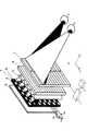
図1は本発明の実施形態1の要部斜視図である。図2は図1の一部分の正面説明図、図3は図1のHZ断面図、図4は図1のVZ断面図である。
【0021】
図中、1は画像表示用の液晶ディスプレイ(LCD,ディスプレイ)であり、カバーガラス、偏光板、カラーフィルター、ブラックマトリックス、電極等を有している。5は照明光源としてのバックライトである。バックライト5の前方には光を透過する開口部(開口)6を市松状に所定のピッチで配列したマスクパターン7を形成したマスク基板4が配置されている。マスクパターン7はクロム等の金属蒸着膜または光吸収材からなり、ガラスまたは樹脂からなるマスク基板4上にパターニングにより製作している。
【0022】
図2に示すようにマスクパターンの垂直方向(V方向)の開口部6a,6bの開口幅Vtと遮光部6cの遮光幅VsとはVt<Vsとなるようにしている。
【0023】
3は水平方向Hに屈折力を有するシリンドリカルレンズを複数個、水平方向に配列した第1レンチキュラーレンズ(縦レンチキュラーレンズ)、2は垂直方向Vに屈折力を有するシリンドリカルレンズを複数個、垂直方向に配列した第2レンチキュラーレンズ(横レンチキュラーレンズ)である。第1、第2レンチキュラーレンズ3,2は、マスク基板4と画像表示用の液晶ディスプレイ1との間に任意の順に配置されている。
【0024】
画像表示用の液晶ディスプレイ1には異なった複数(同図は2つ)視点に対応する2つの視差画像R,Lが後述するように水平方向に順番に横ストライプ状に配列して表示されている。11はディスプレイ駆動回路であり、ディスプレイ1に横ストライプ合成画像を表示している。12は画像処理回路であり、複数視点からの立体物の複数の視差画像から多数の横ストライプ視差画像(視差画像)を切り出して、所定の順序で垂直方向に所定のピッチで繰り返して配列して合成し、これによって横ストライプ合成画像を生成し、ディスプレイ駆動回路11に入力している。
【0025】
バックライト5からの光はマスク基板4の各々の開口部6を透過し、第1、第2レンチキュラーレンズ3,2を通して画像用液晶のディスプレイ1を照明し、ディスプレイ1に表示した複数の視差画像を予め設定された観察位置で分離して、これによってディスプレイ1に表示した画像情報の立体像の観察を行っている。
【0026】
図3は図1のディスプレイ1前方の観察位置において2視点に対応する視差画像が水平方向に分離して観察される原理を示した説明図であり、図1の立体画像表示装置を上から見た断面を示している。図3は第1視点としての左視差画像Lに基づく照明光が左眼ELに集まるようなマスクパターン7の開口部6aを有するラインパターンを含む水平面についての断面図(図2のa−a’断面に相当する図)となっている。
【0027】
図3においては、バックライト5からの光束によりマスク基板4は照明され、マスクパターン7の開口6aから光が出射する。マスク基板4とLCD1の間には第1レンチキュラーレンズ3(第2レンチキュラーレンズ2は水平方向に屈折力を有していないので平板として示している。)が配置され、その各々のシリンドリカルレンズ3aの略焦点位置にマスクパターン7が位置するようにレンズ曲率は設計されている。マスクパターン7の一対の開口部(6a)と遮光部6cが第1レンチキュラーレンズ3のシリンドリカルレンズ3aの1ピッチよりも僅かに大きくなるようにしている。図3に示したマスク基板4上の開口部6aと遮光部6cとからなる1行(水平方向)の開口アレイ(ラインパターン)からの照明光束は第1レンチキュラーレンズ3により、ある方向を指向する略平行光束に変換され、画像表示用の液晶ディスプレイ1に表示された垂直方向に循環的に配列した横ストライプ状の2つの視差画像(横ストライプ視差画像)のうち第1視差画像(左視差画像)Lを照明し、第1視点(左眼)EL付近に集光する。
【0028】
同様に、マスク基板4上の開口部6bと遮光部6cとからなる1行の開口アレイは、先の図2での開口アレイの行から図面上で1行下方向(V方向)にずれた位置での開口アレイであり、図2の開口部6aと遮光部6cのパターンを空間的に水平方向Hに1/2ピッチずらしたパターンより成っている。即ち1つの開口部の幅だけずらしたものとなっている。開口部6bからの照明光束は、同様に第1レンチキュラーレンズ3により先の図3とは異なるある方向を指向する略平行光束に変換され、画像表示用の液晶ディスプレイ1に表示された垂直方向に循環的に配列した横ストライプ状の2つの視差画像のうち第2視差画像(右視差画像)Rを照明し、第2視点(右眼)ERへ集光している。
【0029】
つまりマスク基板4上の開口部6から出射した光束は第1レンチキュラーレンズ3を通して略平行光束となり、画像表示用の液晶ディスプレイ1の各々第1,第2,視差画像L,Rを指向性をもって照明した後、視点EL,ERへ集光している。これによってLCD1に表示した画像情報の立体視を行っている。
【0030】
図4は本発明の立体画像表示装置の上下方向(V方向)の断面の側面概略図(図2のb−b’断面に相当する図)である。次に図4を用いて上下方向の観察領域の説明を行う。
【0031】
図4には、この断面においては光学作用を持たない第1レンチキュラーレンズ3及び光学作用に直接関係しない平面ガラスによる基板を省略しており、第2レンチキュラーレンズ2についても概念的に示している。マスク基板4のマスクパターン7の開口6aは、図2のようなパターンになっており、上下方向には画像表示用の液晶ディスプレイ1に表示された垂直方向に循環的に配列した横ストライプ視差画像の2つの視差画像L,Rに対応して、各行が互いに1/2ピッチずつ水平方向にずれている。
【0032】
図4中のマスクパターン7のラインパターンは2つの視差画像L,Rのうちどれか1視点用の視差画像ラインを照明する為のものである。図4では例として第1視点に対応する左視差画像(第1視差画像)Lのラインパターンを表示するものを示している。開口6a以外の黒く塗りつぶされた部分は光を通さない遮光部6cである。LCD1の第1視点に対応するストライプ状の左視差画像Lを表示しているラインを白、第2視点に対応するストライプ状の右視差画像Rを表示しているラインを黒く塗りつぶして表している。
【0033】
ここで、上下方向のマスクパターン7の開口6aからV方向に隣り合う開口6aまでのピッチVm、第2レンチキュラーレンズ2のシリンドリカルレンズ2aのピッチをVL、第2レンチキュラーレンズ2を構成する個々のシリンドリカルレンズの図4の紙面内の方向の焦点距離fvとし、画像表示用の液晶ディスプレイ1の上下方向(V方向)の画素ピッチをVd,画像表示用の液晶ディスプレイ1の表示面から第2レンチキュラーレンズ2までの距離をL1、第2レンチキュラーレンズ2からマスクパターン7までの距離をL2とするとき、
0.95<{Vd/(Vm/2)}/(L1/L2)<1.05‥‥‥(1)
0.96<(Vd/VL)/{(L1+L2)/(2×L2)}<1.04‥‥‥(2)
0.9 <(1/fv)/(1/L1+1/L2)<1.1 ‥‥‥(3)
の関係を満たすように各々が設定されている。
【0034】
このときマスクパターン7の開口6aの一点からの光束は、それぞれ対応する画素ラインLに図4の紙面に垂直な焦線として集光している。マスクパターン7の第1視点に対応したラインパターンの開口6aのうちの1つの開口6−1に注目すると、図4中の中央の開口6−1の中心の点Aから発せられ、第2レンチキュラーレンズ2の対応するシリンドリカルレンズ2−1に入射する光束は、LCD1の対応する画素列1−1中央の点A′上の焦線に集光される。中央の開口6−1の中心の点Aから発せられシリンドリカルレンズ2−1以外のレンチキュラーレンズを構成するシリンドリカルレンズに入射する光束はLCD6の第1視差画像Lを表示する他の画素ラインの中心に焦線として集光される。
【0035】
また開口6−1の端の点D,Eから発せられ、第2レンチキュラーレンズ2の対応するシリンドリカルレンズ2−1に入射する光束は、画素列1−1の端の点b′,E′上の焦線にそれぞれ集光される。同様に開口6−1のその他の点から発せられシリンドリカルレンズ2−1に入射した光束はLCD1の画素列1−1上に焦線として集光される。また開口6−1を発してシリンドリカルレンズ2−1以外のシリンドリカルレンズに入射した光束も全てLCD1の第1視差画像Lを表示する画素ライン上に集光される。
【0036】
市松状の開口6−1以外の開口部から発せられる光束も、同様に全てLCD1の第1視差画像Lを表示する画素ライン上に集光されてLCD1の第1視差画像ラインLを照明し、その後、これを透過して上下方向にのみ集光時の各光束のNAに応じて発散し、観察者の所定の眼の高さから画面の上下方向の全幅にわたって第1視差画像が一様に分離して見えるような観察領域が得られるようになっている。
【0037】
ここでは観察位置での第1視差画像Lについて説明したが、第2視点に対応する第2視差画像(右視差画像)Rについても同様の働きがある。
【0038】
即ち、画素列1−1の点D’と点B’との差分だけ、組み立て誤差の許容量が広がることになる。
【0039】
従って、マスクパターン7と第2レンチキュラーレンズ2との位置調整が完全な場合を仮定すると、レンチキュラーレンズ2までの照明系とLCD1との垂直方向の位置合せ精度は
Vd・{(2−α)−Vt/(Vm/2)}/2 ‥‥‥(4)
となる。
【0040】
これは先願の立体画像表示装置に比べて、
Vd・{1−Vt/(Vm/2)}/2 ‥‥‥(5)
だけ、位置合せ誤差許容量が大きくなる。
【0041】
図5は、立体画像表示装置の中心を軸とした回転方向の許容量の説明図である。図5(A)はマスクパターン7の開口6a(左眼への光束が透過する開口)から発し、レンチキュラーレンズ3、2を通ってLCD1の画像表示面上に到達した光の照明パターンを示している。図5(B)はLCD1の画素列R,Lを模式的に表した説明図であり、図5(C)は図5(A)の照明パターンと図5(B)の画素列R,Lとの回転方向のずれの説明図である。
【0042】
図2のマスクパターン7の開口6の垂直方向に1ラインずつ間引いた(ここでは右眼開口を間引き、左眼開口について考える)形の開口から射出した光は、第1レンチキュラーレンズ3により水平方向に観察者の左眼の方向へ指向性を与えられ、また、上述したように第2レンチキュラーレンズ2により垂直方向には集光され、LCD1の画像面上で図5(A)に示すような照明パターンを形成する。LCD1の画像表示面上には図5(B)のように水平方向に長い左右の視差画像が垂直方向に順次並んだ画素列R,Lが、ブラックストライプによる遮光部を挟んで並んでいる。尚、ここでは水平方向の画素間のブラックストライプは説明に不要であるため省略した。
【0043】
従って、図5(C)に示したように回転方向に大幅にずれた場合は、図5(A)に示した照明光の一部は、LCD1の画像表示面上のR画素列を通って観察者の左眼に導かれることになるため、クロストーク発生の原因となる。
【0044】
これが発生しないための位置合せの条件は、回転角が
arcsin[Vd・{(2−α)−Vt/(Vm/2)}/W]‥‥‥(6)
(但し、Wはディスプレイの水平方向幅)
以内となる。
【0045】
これは先願の立体画像表示装置における値
arcsin{Vd・(1−α)/W} ‥‥‥(7)
に比べて位置合せ誤差許容量が大きくなっている。
【0046】
今、先願の立体画像表示装置における垂直方向の開口幅Vm/2に対する本実施形態の垂直方向の開口幅Vtの比率Vt/(Vm/2)=β=0.8に設定した場合を考えると、(5),(6),(7)式より垂直方向位置ずれ許容値の絶対量は
0.033mm
だけ増え、回転方向のずれ許容値の絶対量は
0.018°
だけ増え、この場合は公差が倍になる。
【0047】
以上、示したように本実施形態の構成によれば、先願の立体画像表示装置に比して位置合せ精度が低くなるため、組み立て調整段階でのコスト削減を図ることができる。
【0048】
図6は本発明の実施形態2の要部斜視図である。本実施形態は図1の実施形態1に比べてマスク基板4とバックライト5の代わりに、図6に示すように、自発光素子であるCRT8を用いて、発光部と非発光部からなるパターンを形成している点が異なっているだけであり、その他の構成は同じである。
【0049】
本実施形態においても発光部からの光束を図1の実施形態1と同様にして用いて同様の効果を得ている。
【0050】
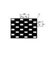
図7は本発明の実施形態3の要部斜視図である。本実施形態は図1の実施形態1に比べてマスクパターンの開口部と遮光部との水平及び垂直方向の幅の関係が異なっており、水平方向の開口部と遮光部の幅Ht,Hsを各々Ht<Hsとなるように設定し、垂直方向の開口部と遮光部の幅Vt,Vsを各々Vt=Vsとしたものであり、その他の構成は同じである。
【0051】
図7において図1で示した要素と同一要素には同符番を付している。
【0052】
本実施形態において、マスクパターン7の開口部6と遮光部のピッチHm(=Hs+Ht)、及びその他の諸元との関係は実施形態1と同様である。図8は本実施形態のマスクパターン7の正面図である。
【0053】
本実施形態において、観察面上にはそれぞれR、L画素からの光が矩形波状にできるが、このとき矩形波の立ち上がりが若干緩いと、R,L画素からの光が交わる場所が生じ、この付近に観察者の眼が位置した場合には、左右の画像の混ざった2重像として認識されることになる場合がある。
【0054】
そこで、本実施形態では、マスクパターン7の水平方向の各開口幅を狭くし、それぞれの開口部を通った光の観察面上に形成する光量分布幅を狭くしている。
【0055】
図9は本実施形態の立体画像表示装置によるR、L画素ラインからの光が観察面上に形成する光量分布を示した図である。図に示すように開口部6の、開口幅Htを制限したことにより、R,L画素ラインそれぞれからの光量分布の交点が光量0に近いところで交差するようになる。このように構成することによって、2重像として認識されるところは、画像が暗い場所として認識されることとなり、観察者にとって画像を見る位置が分かりやすくなるようにしている。
【0056】
尚、本実施形態においてマスクパターンを図10に示すようにマスクパターン7の水平方向と、垂直方向の開口部の開口率をともに下げた構成として、上述の実施形態1,3の利点を併せ持つようにすることも可能である。
【0057】
【発明の効果】
本発明によれば以上のように各要素を特定することによって、装置全体を構成する各要素のうち主要部の組立精度の緩和を図りつつ、広い領域において2重像を見ることなく立体画像を高画質で良好に観察することができる立体画像表示装置を達成することができる。
【図面の簡単な説明】
【図1】本発明の実施形態1の要部斜視図
【図2】図1のマスクパターンの説明図
【図3】図1のHZ断面の説明図
【図4】図1のVZ断面の説明図
【図5】図1の構成における回転ずれの説明図
【図6】本発明の実施形態2の要部斜視図
【図7】本発明の実施形態3の要部斜視図
【図8】図7のマスクパターンの説明図
【図9】図7における観察面上の水平断面での光量分布の説明図
【図10】図7のマスクパターンの他の実施形態の説明図
【符号の説明】
1 ディスプレイ
2 第2レンチキュラーレンズ
3 第1レンチキュラーレンズ
4 マスク基板
5 バックライト(光源手段)
6,6a,6b 開口部
6c 遮光部
7 マスクパターン
11 ディスプレイ駆動回路
12 画像処理回路
L 左視差画像
R 右視差画像[0001]
BACKGROUND OF THE INVENTION
The present invention relates to a stereoscopic image display device, and in particular, when stereoscopic display of image information is performed on a display device (display) such as a television, a video, a computer monitor, or a game machine, and stereoscopic observation of image information is performed from a predetermined observation area. Is preferred.
[0002]
[Prior art]
Conventionally, stereoscopic image observation methods include, for example, a method of observing parallax images based on different polarization states using polarized glasses, or a predetermined parallax from a plurality of parallax images (viewpoint images) using a lenticular lens. A method of guiding an image to an observer's eyeball has been proposed.
[0003]
A method using a lenticular lens that displays a stereoscopic image without applying special polarized glasses is provided with a lenticular lens on the viewer side of the display device to give directivity to each pixel of the parallax image displayed on the display device. The viewer is made to recognize the stereoscopic image.
[0004]
The method using a lenticular lens has the advantage that stereoscopic viewing is possible without using polarized glasses, but this method has the problem that the screen surface is glaring because a lenticular lens sheet is placed in front of the display. Was.
[0005]
On the other hand, the present applicant has achieved a stereoscopic image display apparatus capable of observing an excellent stereoscopic image in a wide area in Japanese Patent Application No. 8-148611.
[0006]
In the same issue, it has a mask pattern having checkered openings, light source means for illuminating the mask pattern, micro optical elements having different optical actions in the horizontal direction and the vertical direction, and a transmissive display device, One image obtained by alternately arranging the right stripe pixel and the left stripe pixel obtained by dividing the parallax image for the right eye and the parallax image for the left eye into a large number of stripe-like pixels on the display device in a predetermined order. The stripe composite image is displayed, and the light beam emitted from the light source means is irradiated with the stripe composite image by providing directivity with the micro optical element, and the light beam is separated into at least two regions. Has proposed a stereoscopic image display apparatus that allows an observer to visually recognize the image as a stereoscopic image. The stereoscopic image display device proposed by the present applicant in the prior Japanese Patent Application No. Hei 8-148611 is hereinafter referred to as a “prior application stereoscopic image display device”.
[0007]
[Problems to be solved by the invention]
The stereoscopic image display device of the prior application has a mask pattern in which a plurality of openings and light-shielding portions are configured in a checkered pattern, and two lenticular lenses made up of a plurality of cylindrical lenses having refractive power in one direction as a micro optical element. The arrangement is such that the lens arrangement directions are orthogonal to each other.
[0008]
As a result, the area where the image information displayed on the display can be stereoscopically viewed is enlarged, and a stereoscopic image can be observed well from a wide range.
[0009]
In general, in order to observe a highly accurate stereoscopic image in a stereoscopic image display apparatus, it is important that the assembly accuracy of each element constituting the entire apparatus is loose.
[0010]
The present invention further improves the stereoscopic image display device of the prior application, and reduces the assembly accuracy of the main part among the elements constituting the entire device, while producing a high-quality stereoscopic image without seeing a double image in a wide area. An object of the present invention is to provide a stereoscopic image display device that can be observed well.
[0011]
[Means for Solving the Problems]
The main image display apparatus according to the first aspect of the present invention includes a first pattern in which a plurality of openings and light-shielding portions arranged in the first direction are alternately arranged in order from the light source side, and the openings and the light-shielding portions. A second direction having a second pattern arranged so as to be shifted by 1/2 pitch with respect to the first pattern in the first direction, wherein the first pattern and the second pattern are perpendicular to the first direction; The first pixels in which the mask patterns alternately arranged, the first lens array having a plurality of lenses arranged in the first direction, and the pixels forming the first parallax image are arranged in the first direction. A display having a row and a second pixel row in which pixels forming a second parallax image are arranged along the first direction, passing through an opening in the first pattern, and the first lens array Is converted into a light beam directed in a certain direction through The first pixel row is illuminated with a first light beam, passes through an opening in the second pattern, and is converted into a light beam that is directed to a different direction from the certain direction via the first lens array. The second pixel row is illuminated with two light beams, and the first and second light beams based on the first and second parallax images are respectively guided to the right and left eyes of the observer, and displayed on the display. A stereoscopic image display device that allows the observer to observe image information stereoscopically, wherein the lengths of the opening and the light shielding portion in the second direction are Vt and Vs, respectively.
Vt <Vs
It is characterized by being set to be.
[0012]
According to a second aspect of the present invention, in the first aspect of the invention, when the lengths of the opening and the light shielding portion in the first direction are Ht and Hs, respectively.
It is characterized by setting so that Ht <Hs.
[0013]
The main image display device of the invention of
A first pattern in which a plurality of openings and light-shielding portions arranged along the first direction are alternately arranged, and a plurality of openings and light-shielding portions arranged along the first direction are arranged alternately. A first pixel array in which a mask pattern having a second pattern, a first lens array having a plurality of lenses arranged in the first direction, and pixels forming a first parallax image are arranged in the first direction And a display having a second pixel column in which pixels forming a second parallax image are arranged along the first direction,
The first pixel row is illuminated with a first light beam that has passed through the opening in the first pattern and converted to a light beam directed in a certain direction through the first lens array, and the opening in the second pattern Illuminating the second pixel row with a second light beam that passes through the first lens array and is converted into a light beam that is directed in a different direction from the certain direction;
By guiding the first and second light fluxes based on the first and second parallax images to the right and left eyes of the viewer, the viewer can observe the image information displayed on the display in a three-dimensional manner. When the lengths of the opening and the light shielding portion in the first direction are Ht and Hs, respectively.
Ht <Hs
It is characterized by being set to be.
[0014]
A stereoscopic image display device according to a fourth aspect of the present invention is the first pattern in which a plurality of light emitting portions and non-light emitting portions arranged along the first direction are alternately arranged, and the light emitting portion and the non-light emitting portion are the first pattern. And having a second pattern arranged so as to be shifted by 1/2 pitch with respect to the first pattern, and the first pattern and the second pattern are alternately arranged in a second direction perpendicular to the first direction. A self-luminous element arranged; a first lens array having a plurality of lenses arranged in the first direction; and a first pixel row in which pixels forming a first parallax image are arranged along the first direction; And a display having a second pixel array in which pixels forming a second parallax image are arranged along the first direction, emitted from a light emitting unit in the first pattern, and via the first lens array By the first light beam converted into a light beam directed in a certain direction. Illuminating the first pixel column, the second light beam emitted from the light emitting unit in the second pattern and converted into a light beam directed to another direction different from the certain direction via the first lens array Illuminating the second pixel column and guiding the first and second light fluxes based on the first and second parallax images to the right and left eyes of the observer, respectively, the image information displayed on the display is A stereoscopic image display apparatus that enables an observer to observe stereoscopically, wherein the lengths of the light emitting part and the non-light emitting part in the second direction are Vt and Vs, respectively.
Vt <Vs
It is characterized by being set to be.
[0015]
The invention of
Ht <Hs
It is characterized by being set to be.
[0016]
According to a sixth aspect of the present invention, there is provided a main image display device comprising: a first pattern in which a plurality of light emitting portions and non-light emitting portions arranged along the first direction are alternately arranged; and light emission arranged along the first direction. A self-light-emitting element having a second pattern in which a plurality of light emitting portions and non-light-emitting portions are alternately arranged, a first lens array having a plurality of lenses arranged in the first direction, and a first parallax image A display having a first pixel column in which pixels are arranged along the first direction, and a second pixel column in which pixels forming a second parallax image are arranged in the first direction; The first pixel column is illuminated by a first light beam emitted from a light emitting unit in one pattern and converted into a light beam directed in a certain direction via the first lens array, and emitted from the light emitting unit in the second pattern. , Another direction different from the certain direction through the first lens array Illuminating the second pixel row by the second light flux is converted into light beam directed to,
By guiding the first and second light fluxes based on the first and second parallax images to the right and left eyes of the viewer, the viewer can observe the image information displayed on the display in a three-dimensional manner. A stereoscopic image display device,
When the lengths in the first direction of the light emitting part and the non-light emitting part are Ht and Hs, respectively.
Ht <Hs
It is characterized by being set to be.
[0017]
The invention of
The invention according to
The invention according to claim 9 is the invention according to
[0020]
DETAILED DESCRIPTION OF THE INVENTION
FIG. 1 is a perspective view of an essential part of Embodiment 1 of the present invention. 2 is a front explanatory view of a part of FIG. 1, FIG. 3 is an HZ sectional view of FIG. 1, and FIG. 4 is a VZ sectional view of FIG.
[0021]
In the figure, reference numeral 1 denotes a liquid crystal display (LCD) for image display, which has a cover glass, a polarizing plate, a color filter, a black matrix, an electrode, and the like.
[0022]
As shown in FIG. 2, the opening width Vt of the
[0023]
[0024]
On the liquid crystal display 1 for image display, two parallax images R and L corresponding to different (two in the figure) viewpoints are displayed in horizontal stripes in order in the horizontal direction as will be described later. Yes. A display driving circuit 11 displays a horizontal stripe composite image on the display 1. An
[0025]
The light from the
[0026]
FIG. 3 is an explanatory diagram showing the principle that a parallax image corresponding to two viewpoints is observed in the horizontal direction at the observation position in front of the display 1 in FIG. 1, and the stereoscopic image display device in FIG. 1 is viewed from above. A cross section is shown. FIG. 3 is a cross-sectional view of a horizontal plane including a line pattern having an
[0027]
In FIG. 3, the
[0028]
Similarly, the opening array in one row composed of the
[0029]
That is, the light beam emitted from the
[0030]
FIG. 4 is a schematic side view of the stereoscopic image display device according to the present invention in a vertical direction (direction V) (a diagram corresponding to the cross section bb ′ in FIG. 2). Next, the observation area in the vertical direction will be described with reference to FIG.
[0031]
In FIG. 4, the first
[0032]
The line pattern of the
[0033]
Here, the pitch Vm from the
0.95 <{Vd / (Vm / 2)} / (L1 / L2) <1.05 (1)
0.96 <(Vd / VL) / {(L1 + L2) / (2 × L2)} <1.04 (2)
0.9 <(1 / fv) / (1 / L1 + 1 / L2) <1.1 (3)
Each is set so as to satisfy the relationship.
[0034]
At this time, the light flux from one point of the
[0035]
Further, light beams emitted from the end points D and E of the aperture 6-1 and incident on the corresponding cylindrical lens 2-1 of the second
[0036]
Similarly, all the light beams emitted from the openings other than the checkered opening 6-1 are condensed on the pixel line displaying the first parallax image L of the LCD 1 to illuminate the first parallax image line L of the LCD 1, After that, the light is transmitted and diverges according to the NA of each light beam when condensing only in the vertical direction, and the first parallax image is uniform from the observer's predetermined eye height to the entire vertical width of the screen. An observation area that appears to be separated can be obtained.
[0037]
Here, the first parallax image L at the observation position has been described, but the second parallax image (right parallax image) R corresponding to the second viewpoint has the same function.
[0038]
That is, the allowable amount of assembly error increases by the difference between the point D ′ and the point B ′ of the pixel column 1-1.
[0039]
Accordingly, assuming that the position adjustment between the
Vd · {(2-α) −Vt / (Vm / 2)} / 2 (4)
It becomes.
[0040]
Compared to the stereoscopic image display device of the previous application,
Vd · {1-Vt / (Vm / 2)} / 2 (5)
As a result, the alignment error tolerance increases.
[0041]
FIG. 5 is an explanatory diagram of the allowable amount in the rotation direction around the center of the stereoscopic image display device. FIG. 5A shows an illumination pattern of light emitted from the
[0042]
The light emitted from the aperture that is thinned out one line at a time in the vertical direction of the
[0043]
Therefore, when the rotation direction is significantly shifted as shown in FIG. 5C, a part of the illumination light shown in FIG. Since it is guided to the left eye of the observer, it causes crosstalk.
[0044]
The alignment condition for preventing this from occurring is that the rotation angle is
arcsin [Vd · {(2-α) −Vt / (Vm / 2)} / W] (6)
(W is the horizontal width of the display)
Within.
[0045]
This is the value in the stereoscopic image display device of the prior application.
arcsin {Vd · (1-α) / W} (7)
In comparison with FIG.
[0046]
Consider a case where the ratio Vt / (Vm / 2) = β = 0.8 of the vertical opening width Vt of the present embodiment to the vertical opening width Vm / 2 in the stereoscopic image display device of the prior application is considered. From the equations (5), (6), and (7), the absolute amount of the vertical displacement tolerance is
0.033mm
The absolute amount of deviation in the rotational direction is
0.018 °
In this case, the tolerance is doubled.
[0047]
As described above, according to the configuration of the present embodiment, since the alignment accuracy is lower than that of the stereoscopic image display device of the prior application, it is possible to reduce the cost at the assembly adjustment stage.
[0048]
FIG. 6 is a perspective view of an essential part of
[0049]
Also in this embodiment, the same effect is obtained by using the light beam from the light emitting portion in the same manner as in the first embodiment of FIG.
[0050]
FIG. 7 is a perspective view of an essential part of
[0051]
In FIG. 7, the same elements as those shown in FIG.
[0052]
In the present embodiment, the relationship between the
[0053]
In the present embodiment, the light from the R and L pixels can be formed in a rectangular wave shape on the observation surface, but if the rising of the rectangular wave is slightly loose at this time, a place where the light from the R and L pixels intersects is generated. When the observer's eyes are located in the vicinity, the image may be recognized as a double image in which the left and right images are mixed.
[0054]
Therefore, in the present embodiment, each opening width in the horizontal direction of the
[0055]
FIG. 9 is a diagram showing a light amount distribution formed on the observation surface by the light from the R and L pixel lines by the stereoscopic image display device of the present embodiment. As shown in the figure, by limiting the opening width Ht of the
[0056]
In this embodiment, as shown in FIG. 10, the mask pattern has the advantages of the above-described first and third embodiments as a configuration in which both the horizontal and vertical aperture ratios of the
[0057]
【The invention's effect】
According to the present invention, by specifying each element as described above, a three-dimensional image can be obtained without looking at a double image in a wide area while reducing the assembly accuracy of the main part of each element constituting the entire apparatus. It is possible to achieve a stereoscopic image display device that can be favorably observed with high image quality.
[Brief description of the drawings]
FIG. 1 is a perspective view of essential parts of Embodiment 1 of the present invention.
FIG. 2 is an explanatory diagram of the mask pattern of FIG.
FIG. 3 is an explanatory diagram of the HZ cross section of FIG.
4 is an explanatory diagram of a VZ cross section in FIG.
FIG. 5 is an explanatory diagram of rotational deviation in the configuration of FIG.
FIG. 6 is a perspective view of main parts of
FIG. 7 is a perspective view of essential parts of
FIG. 8 is an explanatory diagram of the mask pattern of FIG.
FIG. 9 is an explanatory diagram of a light amount distribution in a horizontal section on the observation surface in FIG.
FIG. 10 is an explanatory diagram of another embodiment of the mask pattern of FIG.
[Explanation of symbols]
1 Display
2 Second lenticular lens
3 First lenticular lens
4 Mask substrate
5 Backlight (light source means)
6, 6a, 6b opening
6c Shading part
7 Mask pattern
11 Display drive circuit
12 Image processing circuit
L Left parallax image
R Right parallax image
Claims (9)
Translated fromJapaneseVt<Vs
となるように設定していることを特徴とする立体画像表示装置。In order from the light source side, a first pattern in which a plurality of openings and light-shielding parts arranged alternately in the first direction are alternately arranged, and theopenings and light-shielding parts are in the first direction with respect to the first pattern. A mask pattern in which the first pattern and the second pattern are alternately arranged in a second direction perpendicular to the first direction; A first lens array having a plurality of lenses arranged in one direction; a first pixel array in which pixels forming a first parallax image are arranged along the first direction; and a pixel forming a second parallax image. A display having a second pixel array arranged along the first direction, passing through an opening in the first pattern, and converted into a light beam directed in a certain direction through the first lens array. Illuminating the first pixel row with a first light flux Illuminating the second pixel row with a second light beam that has passed through the opening in the second pattern and converted into a light beam that is directed through a first lens array in a different direction from the certain direction; By guiding the first and second light fluxes based on the first and second parallax images to the right and left eyes of the observer, the observer can observe the image information displayed on the display in a three-dimensional manner. Vt <Vs when the lengths of the opening and the light shielding part inthe second direction are Vt and Vs, respectively.
A stereoscopic image display device characterized by being set to be
Ht<Hs
となるように設定していることを特徴とする請求項1の立体画像表示装置。Ht <Hs where the lengths of the opening and the light shielding part in the first direction are Ht and Hs, respectively.
The stereoscopic image display device according to claim 1, wherein the stereoscopic image display device is set to be
Ht<Hsとなるように設定していることを特徴とする立体画像表示装置。In order from the light source side, a first pattern in which a plurality of openings and light-shielding parts arranged in the first direction are alternately arranged, and a plurality of openings and light-shielding parts arranged in the first direction. A mask pattern having second patterns alternately arranged, a first lens array having a plurality of lenses arranged in the first direction, and pixels forming a first parallax image are arranged in the first direction. A display having a first pixel row and a second pixel row in which pixels forming a second parallax image are arranged along the first direction, passing through an opening in the first pattern, The first pixel row is illuminated with a first light beam converted into a light beam directed in a certain direction through the first lens array, passes through an opening in the second pattern, and passes through the first lens array. A different direction from one direction Illuminating the second pixel row with a second light beam converted into a light beam, and guiding the first and second light beams based on the first and second parallax images to the right eye and the left eye of an observer, respectively. Thus, the stereoscopic image display device enables the observer to stereoscopically observe the image information displayed on the display, and the lengths of the opening and the light shielding portion in the first direction are Ht and Hs, respectively. A stereoscopic image display device, wherein Ht <Hs is set.
Vt<Vs
となるように設定していることを特徴とする立体画像表示装置。A first pattern in which a plurality of light-emitting portions and non-light-emitting portions arranged along the first direction are alternately arranged, and thelight-emitting portion and the non-light-emitting portion are 1 in the first direction with respect to the first pattern. A self-light-emitting element having a second pattern arranged so as to be shifted by two pitches, wherein the first pattern and the second pattern are alternately arranged in a second direction perpendicular to the first direction, and the first direction A first lens array having a plurality of lenses arranged in the first direction, a first pixel array in which pixels forming a first parallax image are arranged along the first direction, and a pixel forming a second parallax image in the first A display having a second pixel array arranged along one direction, and is converted into a light beam emitted from a light emitting portion in the first pattern and directed in a certain direction through the first lens array. The first pixel row is illuminated with one light beam, and the second pattern is illuminated. And illuminating the second pixel row with a second light beam emitted from a light emitting unit in the screen and converted into a light beam that is directed through a first lens array and directed in a different direction from the certain direction. The three-dimensional image enables the observer to observe the image information displayed on the display in three dimensions by guiding the first and second light fluxes based on the second parallax image to the right eye and the left eye of the observer, respectively. In the image display device, Vt <Vs when the lengths of the light emitting portion and the non-light emitting portion inthe second direction are Vt and Vs, respectively.
A stereoscopic image display device characterized by being set to be
Ht<Hs
となるように設定していることを特徴とする請求項4の立体画像表示装置。When the lengths of the light emitting part and the non-light emitting part in the first direction are Ht and Hs, respectively, Ht <Hs
The stereoscopic image display device according to claim 4, wherein the stereoscopic image display device is set to be
Ht<Hs
となるように設定していることを特徴とする立体画像表示装置。A first pattern in which a plurality of light emitting portions and non-light emitting portions arranged along the first direction are alternately arranged, and a plurality of light emitting portions and non-light emitting portions arranged along the first direction are alternately arranged. A self-luminous element having a second pattern arranged, a first lens array having a plurality of lenses arranged in the first direction, and pixels forming a first parallax image arranged in the first direction. A display having one pixel column and a second pixel column in which pixels forming a second parallax image are arranged in the first direction, and emitting from the light emitting unit in the first pattern, The first pixel row is illuminated with a first light beam converted into a light beam directed in a certain direction through the lens array, emitted from a light emitting unit in the second pattern, and the certain direction through the first lens array. Is changed to a light beam directed in a different direction. Illuminating the second pixel row with the second light flux thus formed, and guiding the first and second light fluxes based on the first and second parallax images to the right eye and the left eye of the observer, respectively, thereby displaying the display Is a stereoscopic image display device that allows the observer to observe stereoscopically the image information displayed on the screen, wherein the lengths of the light emitting portion and the non-light emitting portion in the first direction are Ht and Hs, respectively. <Hs
A stereoscopic image display device characterized by being set to be
Priority Applications (4)
| Application Number | Priority Date | Filing Date | Title |
|---|---|---|---|
| JP05101097AJP3630906B2 (en) | 1997-02-18 | 1997-02-18 | Stereoscopic image display device |
| EP98301160AEP0859525B1 (en) | 1997-02-18 | 1998-02-17 | A stereoscopic image display apparatus using a specific mask pattern |
| DE69803496TDE69803496T2 (en) | 1997-02-18 | 1998-02-17 | Stereoscopic image display device with a specific mask pattern |
| US09/025,087US6151062A (en) | 1997-02-18 | 1998-02-17 | Stereoscopic image display apparatus using specific mask pattern |
Applications Claiming Priority (1)
| Application Number | Priority Date | Filing Date | Title |
|---|---|---|---|
| JP05101097AJP3630906B2 (en) | 1997-02-18 | 1997-02-18 | Stereoscopic image display device |
Publications (2)
| Publication Number | Publication Date |
|---|---|
| JPH10232369A JPH10232369A (en) | 1998-09-02 |
| JP3630906B2true JP3630906B2 (en) | 2005-03-23 |
Family
ID=12874822
Family Applications (1)
| Application Number | Title | Priority Date | Filing Date |
|---|---|---|---|
| JP05101097AExpired - Fee RelatedJP3630906B2 (en) | 1997-02-18 | 1997-02-18 | Stereoscopic image display device |
Country Status (4)
| Country | Link |
|---|---|
| US (1) | US6151062A (en) |
| EP (1) | EP0859525B1 (en) |
| JP (1) | JP3630906B2 (en) |
| DE (1) | DE69803496T2 (en) |
Families Citing this family (57)
| Publication number | Priority date | Publication date | Assignee | Title |
|---|---|---|---|---|
| US6387707B1 (en)* | 1996-04-25 | 2002-05-14 | Bioarray Solutions | Array Cytometry |
| US7041510B2 (en) | 1996-04-25 | 2006-05-09 | Bioarray Solutions Ltd. | System and method for programmable illumination pattern generation |
| US7144119B2 (en)* | 1996-04-25 | 2006-12-05 | Bioarray Solutions Ltd. | System and method for programmable illumination pattern generation |
| ES2288760T3 (en) | 1996-04-25 | 2008-01-16 | Bioarray Solutions Ltd. | ELECTROCINETIC ASSEMBLY CONTROLLED BY LIGHT OF PARTICLES NEXT TO SURFACES. |
| IL125210A (en)* | 1998-07-05 | 2003-03-12 | Mvt Multi Vision Technologies | Computerized method for creating a multi-image print |
| EP1119981A1 (en)* | 1998-09-28 | 2001-08-01 | Rose Research, L.L.C. | Method and apparatus for displaying three-dimensional images |
| US6590605B1 (en)* | 1998-10-14 | 2003-07-08 | Dimension Technologies, Inc. | Autostereoscopic display |
| GB9900231D0 (en)* | 1999-01-07 | 1999-02-24 | Street Graham S B | Method and apparatus for control of viewing zones |
| GB2351866A (en)* | 1999-07-07 | 2001-01-10 | Sharp Kk | Stereoscopic display |
| US6513933B1 (en)* | 1999-09-10 | 2003-02-04 | Hitachi, Ltd. | Projector and display system |
| CA2384186C (en)* | 1999-09-17 | 2010-06-01 | Bioarray Solutions, Llc | System and method for programmable illumination pattern generation |
| KR100389249B1 (en)* | 2000-04-29 | 2003-06-25 | 한국과학기술연구원 | Multi-view image display system |
| EP1311839B1 (en) | 2000-06-21 | 2006-03-01 | Bioarray Solutions Ltd | Multianalyte molecular analysis using application-specific random particle arrays |
| US9709559B2 (en) | 2000-06-21 | 2017-07-18 | Bioarray Solutions, Ltd. | Multianalyte molecular analysis using application-specific random particle arrays |
| US7057704B2 (en)* | 2000-09-17 | 2006-06-06 | Bioarray Solutions Ltd. | System and method for programmable illumination pattern generation |
| US20030045005A1 (en) | 2000-10-17 | 2003-03-06 | Michael Seul | Light-controlled electrokinetic assembly of particles near surfaces |
| US8766773B2 (en)* | 2001-03-20 | 2014-07-01 | Lightwaves Systems, Inc. | Ultra wideband radio frequency identification system, method, and apparatus |
| US7545868B2 (en)* | 2001-03-20 | 2009-06-09 | Lightwaves Systems, Inc. | High bandwidth data transport system |
| US7262063B2 (en) | 2001-06-21 | 2007-08-28 | Bio Array Solutions, Ltd. | Directed assembly of functional heterostructures |
| JP4377689B2 (en) | 2001-10-15 | 2009-12-02 | バイオアレイ ソリューションズ リミテッド | Combined analysis of polymorphic loci with simultaneous interrogation and enzyme-mediated detection |
| GB2387664B (en)* | 2002-04-17 | 2005-08-24 | Philip Anthony Surman | Autostereoscopic display |
| KR100462574B1 (en)* | 2002-10-14 | 2004-12-17 | 한국전자통신연구원 | System and method for displaying combination 2D and 3D multi-view image displays and image converting method its |
| AU2003298655A1 (en) | 2002-11-15 | 2004-06-15 | Bioarray Solutions, Ltd. | Analysis, secure access to, and transmission of array images |
| GB0318892D0 (en)* | 2003-08-12 | 2003-09-17 | Dawe Christopher M | Stereoscopic imaging device and machine for fabrication thereof |
| IL157648A0 (en)* | 2003-08-28 | 2009-02-11 | Itzchak Bar Yona | A new method of creating an interlaced image for lenticular displays |
| US7927796B2 (en) | 2003-09-18 | 2011-04-19 | Bioarray Solutions, Ltd. | Number coding for identification of subtypes of coded types of solid phase carriers |
| AU2004276761B2 (en) | 2003-09-22 | 2009-12-24 | Bioarray Solutions, Ltd. | Surface immobilized polyelectrolyte with multiple functional groups capable of covalently bonding to biomolecules |
| US7649688B2 (en)* | 2003-10-08 | 2010-01-19 | Louis Racette | Auto-stereo three-dimensional images |
| EP1692298A4 (en) | 2003-10-28 | 2008-08-13 | Bioarray Solutions Ltd | Optimization of gene expression analysis using immobilized capture probes |
| PT1694859E (en) | 2003-10-29 | 2015-04-13 | Bioarray Solutions Ltd | Multiplexed nucleic acid analysis by fragmentation of double-stranded dna |
| US7848889B2 (en) | 2004-08-02 | 2010-12-07 | Bioarray Solutions, Ltd. | Automated analysis of multiplexed probe-target interaction patterns: pattern matching and allele identification |
| US8486629B2 (en) | 2005-06-01 | 2013-07-16 | Bioarray Solutions, Ltd. | Creation of functionalized microparticle libraries by oligonucleotide ligation or elongation |
| WO2007021940A2 (en)* | 2005-08-18 | 2007-02-22 | Infinite Z, Inc. | Stereoscopic display using polarized eyewear |
| JP4650279B2 (en)* | 2006-01-19 | 2011-03-16 | エプソンイメージングデバイス株式会社 | Electro-optical device and electronic apparatus |
| DE102006009810A1 (en)* | 2006-03-01 | 2007-09-06 | Fries Research & Technology Gmbh | Confocal microscope for e.g. examining biological sample, has matrix component at which reflection of light is provided, where polarization condition of light is adjusted by component at different positions between pinhole sections |
| JP4232807B2 (en)* | 2006-09-06 | 2009-03-04 | セイコーエプソン株式会社 | Electro-optical device and electronic apparatus |
| KR101259011B1 (en)* | 2006-09-15 | 2013-04-29 | 삼성전자주식회사 | Multiview autosterescopic display apparatus with lnterlaced image |
| US7834943B2 (en)* | 2006-12-12 | 2010-11-16 | Tpo Displays Corp. | Reduction of cross-talk in vertical direction for a dual view display devices |
| US20090146915A1 (en)* | 2007-12-05 | 2009-06-11 | Marathe Madhav V | Multiple view display device |
| US8259155B2 (en)* | 2007-12-05 | 2012-09-04 | Cisco Technology, Inc. | Providing perspective-dependent views to video conference participants |
| JP2010109414A (en)* | 2008-10-28 | 2010-05-13 | Seiko Epson Corp | Display device, electronic apparatus, and display method for parallax image data |
| KR101707607B1 (en)* | 2010-03-04 | 2017-02-17 | 삼성디스플레이 주식회사 | Display device |
| US8704879B1 (en) | 2010-08-31 | 2014-04-22 | Nintendo Co., Ltd. | Eye tracking enabling 3D viewing on conventional 2D display |
| KR101285098B1 (en)* | 2010-11-19 | 2013-07-17 | 엘지디스플레이 주식회사 | Apparatus and method for measuring picture quality of stereoscopic display device, picture quality analysis method using the same |
| US8497817B2 (en)* | 2011-06-01 | 2013-07-30 | Lg Display Co., Ltd. | Stereoscopic image display panel and stereoscopic image display device including the same |
| TWI448146B (en)* | 2011-10-14 | 2014-08-01 | Au Optronics Corp | 3d image processing method with a reduced ghost effect and 3d display device thereof |
| JP6008233B2 (en)* | 2012-03-23 | 2016-10-19 | Nltテクノロジー株式会社 | Image display device |
| US9967546B2 (en) | 2013-10-29 | 2018-05-08 | Vefxi Corporation | Method and apparatus for converting 2D-images and videos to 3D for consumer, commercial and professional applications |
| US20150116458A1 (en) | 2013-10-30 | 2015-04-30 | Barkatech Consulting, LLC | Method and apparatus for generating enhanced 3d-effects for real-time and offline appplications |
| US10158847B2 (en) | 2014-06-19 | 2018-12-18 | Vefxi Corporation | Real—time stereo 3D and autostereoscopic 3D video and image editing |
| CN105158918B (en)* | 2015-10-30 | 2017-05-03 | 成都工业学院 | Integrated imaging three-dimensional display device based on rectangular pinhole array |
| CN117704298A (en) | 2019-06-04 | 2024-03-15 | Lg伊诺特有限公司 | lighting fixtures |
| KR102799462B1 (en)* | 2020-03-10 | 2025-04-28 | 삼성디스플레이 주식회사 | Display device and panel bonding system comprising the same |
| KR102858784B1 (en)* | 2020-06-22 | 2025-09-11 | 삼성디스플레이 주식회사 | Display device and panel bonding system comprising the same |
| US20240380876A1 (en)* | 2021-04-12 | 2024-11-14 | Sony Group Corporation | Information processing apparatus, information processing method, and program |
| KR20230136793A (en)* | 2022-03-17 | 2023-09-27 | 삼성디스플레이 주식회사 | Display device and panel bonding system comprising the same |
| WO2025005526A1 (en)* | 2023-06-29 | 2025-01-02 | 삼성전자 주식회사 | Light field display device |
Family Cites Families (15)
| Publication number | Priority date | Publication date | Assignee | Title |
|---|---|---|---|---|
| US4829365A (en)* | 1986-03-07 | 1989-05-09 | Dimension Technologies, Inc. | Autostereoscopic display with illuminating lines, light valve and mask |
| DE3921061A1 (en)* | 1989-06-23 | 1991-01-03 | Hertz Inst Heinrich | DISPLAY DEVICE FOR THREE-DIMENSIONAL PERCEPTION OF IMAGES |
| US5101279A (en)* | 1989-12-14 | 1992-03-31 | Canon Kabushiki Kaisha | Liquid crystal display apparatus having lenticular elements oriented in relation to LC pixel aperture dimensions |
| US5537144A (en)* | 1990-06-11 | 1996-07-16 | Revfo, Inc. | Electro-optical display system for visually displaying polarized spatially multiplexed images of 3-D objects for use in stereoscopically viewing the same with high image quality and resolution |
| GB2267579A (en)* | 1992-05-15 | 1993-12-08 | Sharp Kk | Optical device comprising facing lenticular or parallax screens of different pitch |
| US5428366A (en)* | 1992-09-09 | 1995-06-27 | Dimension Technologies, Inc. | Field sequential color illumination system for liquid crystal display |
| EP0659324B1 (en)* | 1992-09-09 | 2000-04-12 | EICHENLAUB, Jesse B. | Stroboscopic illumination system for video displays |
| GB2272555A (en)* | 1992-11-11 | 1994-05-18 | Sharp Kk | Stereoscopic display using a light modulator |
| JP2951202B2 (en)* | 1994-02-23 | 1999-09-20 | 三洋電機株式会社 | 3D display without glasses |
| US5629797A (en)* | 1995-05-03 | 1997-05-13 | Ridgway; Michael | Autostereoscopic image system |
| JPH0915532A (en)* | 1995-06-29 | 1997-01-17 | Canon Inc | Stereoscopic image display method and stereoscopic image display device using the same |
| JPH0918897A (en)* | 1995-07-03 | 1997-01-17 | Canon Inc | 3D image display device |
| GB2302978A (en)* | 1995-07-04 | 1997-02-05 | Sharp Kk | LIquid crystal device |
| DE69735736T2 (en)* | 1996-01-31 | 2006-11-02 | Canon K.K. | Stereoscopic image display device with broadened field of view |
| JP3703225B2 (en)* | 1996-09-02 | 2005-10-05 | キヤノン株式会社 | Stereoscopic image display method and stereoscopic image display apparatus using the same |
- 1997
- 1997-02-18JPJP05101097Apatent/JP3630906B2/ennot_activeExpired - Fee Related
- 1998
- 1998-02-17DEDE69803496Tpatent/DE69803496T2/ennot_activeExpired - Lifetime
- 1998-02-17USUS09/025,087patent/US6151062A/ennot_activeExpired - Fee Related
- 1998-02-17EPEP98301160Apatent/EP0859525B1/ennot_activeExpired - Lifetime
Also Published As
| Publication number | Publication date |
|---|---|
| DE69803496D1 (en) | 2002-03-14 |
| JPH10232369A (en) | 1998-09-02 |
| DE69803496T2 (en) | 2002-07-11 |
| EP0859525A2 (en) | 1998-08-19 |
| EP0859525B1 (en) | 2002-01-23 |
| EP0859525A3 (en) | 1999-03-24 |
| US6151062A (en) | 2000-11-21 |
Similar Documents
| Publication | Publication Date | Title |
|---|---|---|
| JP3630906B2 (en) | Stereoscopic image display device | |
| JP5316909B2 (en) | Stereoscopic image display device and display panel | |
| KR100561401B1 (en) | Image display unit of multi-view 3D image system compatible with 2D and 3D image | |
| JP3565400B2 (en) | Automatic stereo display | |
| US6445406B1 (en) | Stereoscopic image display apparatus whose observation area is widened | |
| KR100658545B1 (en) | Apparatus for reproducing stereo-scopic picture | |
| US6246451B1 (en) | Stereoscopic image displaying method and stereoscopic image apparatus | |
| KR100627763B1 (en) | Multiple view display | |
| US6462871B1 (en) | Stereoscopic image display apparatus using specific mask pattern | |
| JP3642736B2 (en) | Directional display | |
| JPH10221643A (en) | 3D image display device | |
| JP2000102039A (en) | 3D image display device | |
| JPH10221644A (en) | 3D image display device | |
| JP2015084079A (en) | Image display device | |
| US7265902B2 (en) | Display apparatus switchable between a two-dimensional display and a three-dimensional display | |
| JP5449238B2 (en) | 3D image display device | |
| JP2001086533A (en) | Stereoscopic image display device | |
| JP2005157332A (en) | Stereoscopic image display device, portable terminal device, display panel, and fly-eye lens | |
| JP3728013B2 (en) | Stereoscopic image display device | |
| JP2009093989A (en) | Plane light source apparatus and liquid crystal display device | |
| JP3647140B2 (en) | Stereoscopic image display method and stereoscopic image display apparatus using the same | |
| JP2003035885A (en) | 3D image display device | |
| JP2005091445A (en) | Image display device | |
| JP2004280079A (en) | Picture display device and portable terminal device using the same | |
| JPH11285031A (en) | Stereoscopic image display device |
Legal Events
| Date | Code | Title | Description |
|---|---|---|---|
| A131 | Notification of reasons for refusal | Free format text:JAPANESE INTERMEDIATE CODE: A131 Effective date:20040224 | |
| A521 | Request for written amendment filed | Free format text:JAPANESE INTERMEDIATE CODE: A523 Effective date:20040426 | |
| A131 | Notification of reasons for refusal | Free format text:JAPANESE INTERMEDIATE CODE: A131 Effective date:20040615 | |
| A521 | Request for written amendment filed | Free format text:JAPANESE INTERMEDIATE CODE: A523 Effective date:20040803 | |
| TRDD | Decision of grant or rejection written | ||
| A01 | Written decision to grant a patent or to grant a registration (utility model) | Free format text:JAPANESE INTERMEDIATE CODE: A01 Effective date:20041130 | |
| A61 | First payment of annual fees (during grant procedure) | Free format text:JAPANESE INTERMEDIATE CODE: A61 Effective date:20041215 | |
| R150 | Certificate of patent or registration of utility model | Free format text:JAPANESE INTERMEDIATE CODE: R150 | |
| FPAY | Renewal fee payment (event date is renewal date of database) | Free format text:PAYMENT UNTIL: 20081224 Year of fee payment:4 | |
| FPAY | Renewal fee payment (event date is renewal date of database) | Free format text:PAYMENT UNTIL: 20081224 Year of fee payment:4 | |
| FPAY | Renewal fee payment (event date is renewal date of database) | Free format text:PAYMENT UNTIL: 20091224 Year of fee payment:5 | |
| FPAY | Renewal fee payment (event date is renewal date of database) | Free format text:PAYMENT UNTIL: 20091224 Year of fee payment:5 | |
| FPAY | Renewal fee payment (event date is renewal date of database) | Free format text:PAYMENT UNTIL: 20101224 Year of fee payment:6 | |
| FPAY | Renewal fee payment (event date is renewal date of database) | Free format text:PAYMENT UNTIL: 20111224 Year of fee payment:7 | |
| LAPS | Cancellation because of no payment of annual fees |