JP3629556B2 - Color synthesis / decomposition optics - Google Patents
Color synthesis / decomposition opticsDownload PDFInfo
- Publication number
- JP3629556B2 JP3629556B2JP25099793AJP25099793AJP3629556B2JP 3629556 B2JP3629556 B2JP 3629556B2JP 25099793 AJP25099793 AJP 25099793AJP 25099793 AJP25099793 AJP 25099793AJP 3629556 B2JP3629556 B2JP 3629556B2
- Authority
- JP
- Japan
- Prior art keywords
- light
- polarization
- wavelength
- wavelength region
- phase plate
- Prior art date
- Legal status (The legal status is an assumption and is not a legal conclusion. Google has not performed a legal analysis and makes no representation as to the accuracy of the status listed.)
- Expired - Lifetime
Links
- 230000015572biosynthetic processEffects0.000titleclaimsdescription9
- 238000003786synthesis reactionMethods0.000titleclaimsdescription9
- 238000000354decomposition reactionMethods0.000title1
- 230000010287polarizationEffects0.000claimsdescription118
- 230000003287optical effectEffects0.000claimsdescription53
- 238000000926separation methodMethods0.000claimsdescription44
- 239000003086colorantSubstances0.000claimsdescription17
- 230000002194synthesizing effectEffects0.000claimsdescription9
- 238000003384imaging methodMethods0.000description20
- 239000004973liquid crystal related substanceSubstances0.000description9
- 230000005540biological transmissionEffects0.000description4
- 238000010586diagramMethods0.000description4
- 239000000203mixtureSubstances0.000description4
- 229910010413TiO 2Inorganic materials0.000description2
- 238000006243chemical reactionMethods0.000description2
- 238000010030laminatingMethods0.000description2
- 239000000758substrateSubstances0.000description2
- 238000002834transmittanceMethods0.000description2
- 229910004298SiO 2Inorganic materials0.000description1
- 230000000694effectsEffects0.000description1
- 239000011521glassSubstances0.000description1
Images

Landscapes
- Video Image Reproduction Devices For Color Tv Systems (AREA)
- Color Television Image Signal Generators (AREA)
Description
Translated fromJapanese【0001】
【産業上の利用分野】
本発明は、カラー映像を表示するプロジェクタ装置や、カラー映像を撮像する撮像装置等において、色合成乃至色分解するために設けられる色合成・分解光学系に関するものである。
【0002】
【従来の技術】
例えば、3板式の固体撮像装置においては、被写体からの光をR(赤),G(緑),B(青)の3原色の波長成分に分解して、3枚設けた固体撮像素子のそれぞれにRGBの各波長成分の光をそれぞれ受光させて、光電変換させることによって、RGBの各色画像信号を取得するが、この被写体からの光を色分解するための光学系としては、ダイクロイックプリズムが一般に用いられる。また、RGBの各色の画像を合成してカラー画像を作り出し、これをスクリーンに投射するプロジェクタ装置においては、RGBの3色の画像を合成するための色合成光学系として、やはりダイクロイックプリズムが用いられる。
【0003】
ダイクロイックプリズムは、周知のように、プリズムの所定の面に多層膜干渉フィルタからなるダイクロイック膜を積層し、例えば赤色の波長成分光を反射させ、他の波長成分光を透過させるダイクロイック膜と、緑色の波長成分光を透過させ、他の波長成分光を反射させるダイクロイック膜とを接合プリズムの所要のプリズム面に形成することによって、可視光を所定の方向から入射すると、RGBの3色に分解でき、また逆にRGBの3原色をそれぞれ所定の方向からプリズムに入射すれば、各波長成分光が順次合成されて、自然色光として出力されることになる。
【0004】
【発明が解決しようとする課題】
ところで、前述したダイクロイックプリズムにおけるダイクロイック膜は、角度依存性があり、このダイクロイック膜に対して垂直に入射される光は正確に反射または透過させるが、入射角が変化すると、反射または透過特性が変化してしまう。従って、発散光や収束光をダイクロイック膜に入射すると、このダイクロイック膜への入射角度に応じて透過率または反射率が部分的に変化するために、部分的に色のバランスが取れなくなり、色再現性や色分解性が低下して、映像の画質が低下するという問題点がある。とりわけ、ダイクロイックプリズムはガラス等の媒質で形成されているから、この媒質の屈折率の関係から、プリズムへの入射角よりダイクロイック膜への入射角の方が大きくなることから、色再現性は極めて悪くなってしまうという不都合が生じる。勿論、ダイクロイック膜の角度依存性を少なくすることも理論的には可能ではあるが、所期の目的を達成する程度にまで角度依存性をなくすには、ダイクロイック膜の層数を100層乃至それ以上としなければならず、このために実用的には、角度依存性をなくすことはできない。
【0005】
このような状況から、従来技術においては、色合成・分解光学系に対しては、ほぼ平行光とした状態で入射することによって、色再現性の低下を防止するようにしていた。このためには、ダイクロイックプリズムがある程度大型化すると共に、それに対する光の入射角を平行光束化するためのレンズを必要とする等、全体としての装置構成が大型化する等といった問題点がある。
【0006】
本発明は、以上の従来技術における課題に鑑みて、小型でコンパクトな構成で、色の変化を極力防止できるようにした色合成・分解光学系を提供することを目的としてなされたものである。
【0007】
【課題を解決するための手段】
前述した目的を達成するために、本発明において、色合成光学系の構成における特徴は、R,G,Bの各波長領域の直線偏光のうち、所定の波長領域のみは、その偏光方向を変え、残りの波長領域については偏光方向を変えずに透過させる特性を発揮するように、3枚以上の波長板を用いて、それぞれの光学軸が所定角度となるように貼り合わせた波長板からなる位相板を、光軸方向に離間させた一対の偏光分離部材の間に配置し、異なる波長領域の光を前記偏光分離部材により同一の光路を取らせ、かつ前記位相板で偏光方向が一致するように変換する構成としたことにある。また、色分解光学系として構成した場合の特徴は、直線偏光としたR,G,Bの各波長領域の光のうち、所定の波長領域のみは、その偏光方向を変え、残りの波長領域については偏光方向を変えずに透過させる特性を発揮するように、3枚以上の波長板を用いて、それぞれの光学軸が所定角度となるように貼り合わせた波長板からなる位相板と、光軸方向において、少なくともこの位相板の後方に配置された偏光分離部材とからなり、前記異なる波長領域の光を前記位相板で偏光方向が相直交するように変換して、前記偏光分離部材によりそれぞれの波長領域の光路を分離させる構成としたものである。
【0008】
また、本発明において、3原色の波長領域の光を自然色光となるように合成するための合成光学系は、それぞれ光路に対して45°の角度を持った偏光分離膜を有する偏光ビームスプリッタを光軸方向に2個設けると共に、これら第1,第2の偏光ビームスプリッタ間に位相板を介装し、前記第1の偏光ビームスプリッタは、R,G,Bの3原色の波長領域のうち、所定の偏光方向の直線偏光からなる第1の波長領域光は透過させ、この第1の直線偏光とは異なる偏光方向の直線偏光である第2の波長成分の光は反射させる偏光分離膜を形成したものであり、前記位相板は、所定の波長領域のみは、その偏光方向を変え、残りの波長領域については偏光方向を変えずに透過させる特性を発揮するように、3枚以上の波長板を用いて、それぞれの光学軸が所定角度となるように貼り合わせた波長板から構成され、また前記第2の偏光ビームスプリッタは、偏光方向が調整された第1,第2の波長領域の光を透過または反射させ、これとは偏光方向の異なる直線偏光からなる第3の波長領域を反射または透過させる偏光分離膜を形成したものであることを特徴とする。
【0009】
さらに、RGBの3原色の色分解を行うための構成とする場合には、それぞれ光路に対して45°の角度を持った偏光分離膜を有する第1,第2の偏光ビームスプリッタと、第1,第2の位相板とを備え、光の入射側から順に、3原色の波長領域のうちの第1の波長領域を選択的に偏光方向を変える第1の位相板、このように偏光方向を変えた第1の波長領域を他の波長領域から分離する第1の偏光ビームスプリッタ、この第1の偏光ビームスプリッタで分離された他の波長領域のうち、第2の波長領域を選択的に偏光方向を変える第2の位相板、それぞれ偏光方向が異なる第2,第3の波長領域の光を分離する第2の偏光ビームスプリッタを配置する構成となし、前記第1,第2の位相板は、所定の波長領域のみは、その偏光方向を変え、残りの波長領域については偏光方向を変えずに透過させる特性を発揮するように、3枚以上の波長板を用いて、それぞれの光学軸が所定角度となるように貼り合わせた波長板で構成されたものであることをその特徴とするものである。
【0010】
【作用】
本発明においては、色合成や色分解を行うに当って、ダイクロイック膜を用いずに、偏光分離膜を備えた偏光分離部材として、例えば偏光ビームスプリッタを用いる。偏光ビームスプリッタは、周知のように、プリズムに45°の角度を持たせて偏光分離膜を設けてなるものであり、この偏光分離膜は、それに入射される光のうち、一般的にP偏光成分,S偏光成分と呼ばれる直交する2つの直線偏光成分のうち、一方の直線偏光成分、例えばP偏光成分は透過させ、他方の直線偏光成分、例えばS偏光成分は反射する性質を有する。従って、2色の波長成分光を合成するには、一方の波長成分光をP偏光とし、他方の波長成分光をS偏光として、偏光ビームスプリッタに相互に90°の方向から入射すると、P偏光成分は偏光分離膜を透過し、S偏光成分はこの偏光分離膜で反射するので、2つの光が合成される。ここで、偏光ビームスプリッタに入射するには、直線偏光成分の光でなければならないが、ランダム偏光の光等からP偏光またはS偏光というように直線偏光とするには、例えば液晶板等からなる偏光板を用いれば良い。
【0011】
そして、この出力光にさらに別の第3の波長成分光を合成するために、偏光ビームスプリッタをもう1個光軸方向に並べる。ただし、前述した第1の偏光ビームスプリッタからの出力光は、一方の波長成分光はP偏光であり、他方の波長成分光はS偏光であるために、この第1の偏光ビームスプリッタからの出力光をそのまま第2の偏光ビームスプリッタに入射したのでは、その偏光分離膜で再び両波長成分の光が分離してしまう。このために、第1の偏光ビームスプリッタと第2の偏光ビームスプリッタとの間に位相板を介在させる。ここで、位相板は複数枚の波長板からなり、これら各波長板の光学軸をそれぞれ所定角度に設定して貼り合わせたもので構成され、直線偏光成分の光を、所定の波長成分のみの偏光方向を変え、残りの波長成分を偏光方向を変えずに透過させるものである。即ち、前述した一方の波長成分光をS偏光させるか、または他方の波長成分光をP偏光させることによって、これら2つの波長成分光の偏光方向を一致させる。これによって、第2の偏光ビームスプリッタで、前述した第1の偏光ビームスプリッタと同様に、2方向からのP偏光及びS偏光からなる入射光を合成することができ、これによってRGBの3原色の光を合成できる。
【0012】
ここで、第2の偏光ビームスプリッタからの出力光は、やはりP偏光成分とS偏光成分とが混在している。これらの偏光方向を一致させるには、第1の位相板と同様に、波長選択性のある第2の位相板をこの第2の偏光ビームスプリッタの出力側に配置する構成とすれば良い。このように、位相板は偏光方向を一致させる機能も発揮する。
【0013】
一方、自然光のうちの可視光領域の波長成分をRGBの各波長成分の要素光に分離するには、前述とは反対に第2の位相板でこれらの要素光のうちの1の波長成分の光を選択的に偏光方向を変えた上で、第2の偏光ビームスプリッタでこの第2の位相板で偏光方向を変えた1つの要素光を他から分離する。そして、残りの2つの要素光を含む他の光を第1の位相板で一方の要素光の波長成分の偏光方向を変えて、第1の偏光ビームスプリッタで2つの要素光を分離することによって、RGBの各波長成分からなる要素光に分解できる。
【0014】
而して、偏光分離膜は、ダイクロイック膜と比較して入射角度に対する反射または透過の特性が変化する割合が少なく、また偏光分離膜の積層数や各層の組成や厚みを変えることによって、20層乃至それ以下の層数でも角度依存性が実質的に無視できる程度にまで少なくでき、収束光や発散光というように、入射角度がかなり大きくても、殆ど反射,透過の特性が変化しないようになる。従って、光学系自体を小型化でき、かつ平行光束化するためのレンズ系等を設けなくとも良くなり、プロジェクション装置,撮像装置等として用いた場合に、簡単な構成で、色再現性,色分解性は極めて良好となる。
【0015】
【実施例】
以下、本発明の実施例を図面に基づいて詳細に説明する。
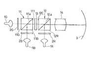
まず、図1に色合成を行うための光学系をプロジェクション装置に組み込むようにしたものの概略構成を示す。図中において、1Gは緑色の画像を出力する第1の受像管、1Bは青色の画像を出力する第2の受像管、1Rは赤色の画像を出力する第3の受像管をそれぞれ示す。また、これら各受像管1G,1B,1Rの出力側には、偏光板としての液晶板2G,2B,2Rが配置されている。3はスクリーンを示し、第1乃至第3の受像管1G,1B,1RからのRGBの各色の画像は光合成光学系10を介して合成されて、スクリーン3にカラー画像が投射される。
【0016】
色合成光学系10は、第1,第2の偏光ビームスプリッタ11,12と、これら2つの偏光ビームスプリッタ11,12間に配設した位相板13とから構成される。偏光ビームスプリッタ11,12は、それぞれ45°の角度をもって偏光分離膜11a,12aが設けられている。
【0017】
第1の受像管1Gからの緑色波長成分の光を液晶板2Gによって、P偏光となされて、第1の偏光ビームスプリッタ11の入射面11Gから入射されるようになっており、また第2の受像管1Bからの青色波長成分の光が液晶板2BによってS偏光となし、第1の偏光ビームスプリッタ11の入射面11Bに入射されるようになっている。そして、この第1の偏光ビームスプリッタ11の偏光分離膜11aは、P偏光は透過させ、S偏光を反射させるものである。従って、第1の偏光ビームスプリッタ11の出射面11Tから出射される光は緑色の波長成分と青色の波長成分とが合成されたものとなる。
【0018】
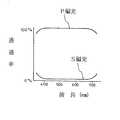
第1の偏光ビームスプリッタ11から出射される光のうち、緑色の波長成分はP偏光であり、青色の波長成分はS偏光である。そこで、これら相異なる偏光方向を一致させるために、位相板13が用いられる。この位相板13は後述するように、複数枚の1/2波長板からなり、波長選択性を持ったものである。即ち、位相板13は、図2に実線で示したように、400nm〜500nmの波長領域の光をS偏光からP偏光に偏光方向を変え、またP偏光である緑色の波長領域の光はそのまま透過する特性を有するものである。従って、この位相板13からの出力光は、共にP偏光となった緑色の波長成分と青色の波長成分とを含む一次合成光である。
【0019】
次に、位相板13からの緑色の波長成分の光と青色の波長成分の光とからなる一次合成光に、赤色の波長成分の光を合成させることによって、カラー画像の合成が行われる。このために、第2の偏光ビームスプリッタ12が設けられている。この第2の偏光ビームスプリッタ12の入射面12Cには、前述したP偏光からなる一次合成光が入射されるようになっており、またこの入射面12cとは90°の方向から、入射面12Rに対して第3の受像管1Rから液晶板2Rを経てS偏光となった赤色の波長成分光が入射されることになる。そして、このように2方向から入射された光のうち、P偏光の一次合成光は偏光分離膜12aを透過し、S偏光である赤色波長成分光はこの偏光分離膜12aで反射して、RGBの3原色の光が合成される。この第2の偏光ビームスプリッタ12からの出力光をプロジェクション用レンズ14を介してスクリーン3にカラー画像を映し出すことができる。
【0020】
ここで、偏光分離膜11a,12aは、図3に示したように、可視光領域(即ち、400nm〜700nmにおいて、P偏光をほぼ100%透過させ、またS偏光をほぼ100%反射させる機能を備え、かつ角度依存性を極力抑制するように構成する。偏光分離膜は、通常、TiO2 ,ZnO2 ,SiO2 ,MgF2 等の誘電体膜を多層に積層してなるものであり、これらの組成,積層数,膜厚等を適宜選択・設定することによって、所望の特性のものが得られる。例えば、偏光分離膜として、TiO2 とMgF2 とを用い、前者をH、後者をLとした時に、基板(45°)/(HL)5 H/接合/基板の11層膜とすれば良い。
【0021】
また、位相板13は、図2に示した特性を持ったものとするが、このためには、貼り合わせにより複数層の波長板で位相板13を構成する。そして、この貼り合わせ時には、これら各波長板の光学軸をそれぞれ所定の角度に設定する。これによって、所定の波長領域の光は偏光方向が変わり、それ以外の波長領域の光は偏光方向が不変の状態で透過するように制御することができる。例えば、青色の波長領域の光の偏光方向を90°回す位相板13を構成するには、中心波長600nmのλ/2波長板3枚を用い、それらの光軸を28.5°,55°,28.5°に配置させ、入射角の偏光方向の角度を0とすれば良い。
【0022】
以上のように、色合成を行うに当って、偏光ビームスプリッタを用いるように構成することによって、入射角による透過率及び反射率の変化が抑制されるので、収束光や発散光であっても、スクリーン3に映し出されるカラー画像の色再現性が良好となるので、この色合成を行う光学系を著しく小型化、コンパクト化できると共に、各受像管からの映像を平行光束化する必要がないので、プロジェクション装置の全体構成を小型化,簡略化できるようになる。
【0023】
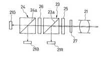
次に、図4に本発明の第2の実施例を示す。本実施例においては、被写体を撮像する固体撮像装置において、RGBの3色に色分解するための光学系として用いた場合を示す。
【0024】
図中において、21は結像レンズ、22R,22B,22Gはそれぞれ赤,青,緑の各色の画像を撮像する固体撮像素子である。結像レンズ21で撮影した被写体像は、色分解光学系によって3色に色分解されて、それぞれ固体撮像素子22R,22B,22Gによりそれぞれ電気信号に変換されるようになっている。而して、色分解光学系は、2個の偏光ビームスプリッタ23,24と2個の位相板25,26とから構成される。偏光ビームスプリッタ23,24は、前述した第1の実施例の偏光ビームスプリッタ11,12と同様の構成となっている。結像レンズ21に近い側の偏光ビームスプリッタを第1の偏光ビームスプリッタ23とし、また結像レンズ21から遠い側の偏光ビームスプリッタを第2の偏光ビームスプリッタ24とする。また、両偏光ビームスプリッタ23,24間に位置する位相板25は、前述した第1の実施例の位相板13と全く同様の構成を有するものであり、この位相板を第2の位相板26とする。また、第1の偏光ビームスプリッタ23における結像レンズ21側に位置する位相板は第1の位相板25とする。さらに、この第1の位相板25と結像レンズ21との間には、結像レンズ21から入射される光をP偏光となるように調整する偏光板としての液晶板27が介装されている。
【0025】
ここで、第1の位相板25は、結像レンズ21から入射される光が液晶板27でP偏光に整えられた状態で入射されると、この光の波長成分のうち、600nm〜700nm、即ち赤色の波長成分の光がS偏光に変えられ、他の波長成分は透過する、図2の点線で示した特性を持ったものを用いる。
【0026】
以上のように構成すると、被写体の像は結像レンズ21を介して撮像装置に取り込まれて、まず液晶板27により入射光の偏光方向がP偏光となる。そして、第1の位相板25において、赤色の波長成分だけが選択的にS偏光に変換され、他の波長成分はP偏光のままこの第1の位相板25を透過する。これが第1の偏光ビームスプリッタ23に入射されると、その偏光分離膜23aで赤色の波長成分が他から分離されて、固体撮像素子22Rに入射される。また、第1の偏光ビームスプリッタ23の偏光分離膜23aを透過した光は、第2の位相板26によって、青色の波長成分だけがS偏光され、緑色の波長成分はP偏光のまま透過する。そして、この光は第2の偏光ビームスプリッタ24の偏光分離膜24aによって青色の波長成分と緑色の波長成分とに分けられて、それぞれ固体撮像素子22B,22Gに入射される。従って、これら固体撮像素子22R,22B,22Gで光電変換されて、RGBの各色の画像信号が生成される。而して、このように、偏光ビームスプリッタを用いることによって、入射光が発散光や収束光であっても、正確に色分解することができる。
【0027】
なお、前述した第1の実施例である色合成を行う光学系において、第2の実施例で示した第2の位相板と同様の部材を設けるように構成すれば、RGBの出力光の偏光方向は全て同一となるように揃えられる。また、各実施例における偏光ビームスプリッタにおいては、P偏光を透過させ、S偏光を反射させるようにしたが、これとは逆にS偏光を透過させ、P偏光を反射させるように構成したものを用いることもできることは言うまでもない。
【0028】
【発明の効果】
本発明は、以上のように構成したので、小型でコンパクトな構成によって、RGBの各色の画像を合成してカラー画像を形成したり、また可視光をRGBの3色に分解したり等を行う際に、入射される光が発散光や収束光であっても、色再現性が良好となり、また色分解を極めて高精度に行うことができる等といった効果を奏する。
【図面の簡単な説明】
【図1】本発明の色合成・分解光学系を色合成光学系として構成し、この色合成光学系を備えたプロジェクション装置の構成説明図である。
【図2】位相板の偏光特性線図である。
【図3】偏光ビームスプリッタの特性線図である。
【図4】本発明の色合成・分解光学系を色分解光学系として構成し、この色分解光学系を備えた固体撮像装置の構成説明図である。
【符号の説明】
1B,1G,1R 受像管
2B,2G,2R,27 液晶板
3 スクリーン
11,12,23,24 偏光ビームスプリッタ
13,25,26 位相板
21 結像レンズ
22B,22G,22R 固体撮像素子[0001]
[Industrial application fields]
The present invention relates to a color synthesizing / separating optical system provided for color synthesis or color separation in a projector apparatus that displays a color video, an imaging apparatus that captures a color video, or the like.
[0002]
[Prior art]
For example, in a three-plate type solid-state imaging device, each of three solid-state imaging devices provided by decomposing light from a subject into wavelength components of three primary colors of R (red), G (green), and B (blue). The RGB color component signals are respectively received and photoelectrically converted to obtain RGB color image signals. A dichroic prism is generally used as an optical system for color-separating the light from the subject. Used. Further, in a projector device that synthesizes RGB images to create a color image and projects the image on a screen, a dichroic prism is also used as a color synthesis optical system for synthesizing the RGB three-color images. .
[0003]
As is well known, a dichroic prism is formed by laminating a dichroic film composed of a multilayer interference filter on a predetermined surface of a prism, for example,reflecting a red wavelength component light and transmitting another wavelength component light, and a green color. By forming a dichroic film that transmits the other wavelength component light and reflecting the other wavelength component light on the required prism surface of the cemented prism, when visible light is incident from a predetermined direction, it can be decomposed into three colors of RGB. Conversely, if the three primary colors of RGB are incident on the prism from predetermined directions, the respective wavelength component lights are sequentially synthesized and output as natural color light.
[0004]
[Problems to be solved by the invention]
By the way, the dichroic film in the dichroic prism described above has angle dependency, and light incident perpendicularly to the dichroic film accurately reflects or transmits, but when the incident angle changes, the reflection or transmission characteristics change. Resulting in. Therefore, when diverging light or convergent light is incident on the dichroic film, the transmittance or reflectance changes partially depending on the incident angle to the dichroic film, so that the color balance cannot be achieved partially, and color reproduction is achieved. There is a problem that the image quality of the video is deteriorated due to a decrease in the image quality and color separation. In particular, since the dichroic prism is made of a medium such as glass, the incident angle to the dichroic film is larger than the incident angle to the prism because of the refractive index of this medium, so the color reproducibility is extremely high. The inconvenience of getting worse occurs. Of course, it is theoretically possible to reduce the angle dependency of the dichroic film, but in order to eliminate the angle dependency to the extent that the intended purpose is achieved, the number of layers of the dichroic film can be 100 layers or more. For this reason, the angle dependency cannot be eliminated practically.
[0005]
Under such circumstances, in the prior art, the color reproducibility optical system is prevented from being deteriorated in color reproducibility by being incident in a substantially parallel light state. For this purpose, the dichroic prism is increased in size to some extent, and a lens for converting the incident angle of light to the parallel beam into a parallel light beam is required.
[0006]
SUMMARY OF THE INVENTION The present invention has been made in view of the problems in the prior art described above, and an object of the present invention is to provide a color synthesizing / separating optical system capable of preventing color change as much as possible with a compact and compact configuration.
[0007]
[Means for Solving the Problems]
In order to achieve the above-described object, in thepresent invention, the color synthesis optical system is characterized by changing the polarization direction of only a predetermined wavelengthregionout of linearly polarized light in eachof the R, G, and B wavelengthregions. The remaining wavelengthregion iscomposed of a wave plate bonded using three or more wave plates so that each optical axis is at a predetermined angle so as to exhibit the characteristic of transmitting without changing the polarization direction.A phase plate is disposed between a pair of polarization separation members spaced apart in the optical axis direction, and light of different wavelength regions is caused to take the same optical path by the polarization separation member, and the polarization direction is matched by the phase plate. Thus, the conversion is performed.In addition, when configured as a color separation optical system, a characteristic is that among the light in the R, G, and B wavelength regions that are linearly polarized, only the predetermined wavelength region is changed in its polarization direction, and the remaining wavelength regions are changed. Is a phase plate composed of a wave plate bonded with an optical axis of a predetermined angle using three or more wave plates so as to exhibit a characteristic of transmitting without changing the polarization direction, and an optical axis A polarization separation member disposed at least behind the phase plate in the direction, and converts the light in the different wavelength regions so that the polarization directions are orthogonal to each other by the phase plate. The optical path in the wavelength region is separated.
[0008]
Further, in the present invention, a combining optical system for combining light in the wavelengthregions of the three primary colors so as to become natural color light includes a polarizing beam splitter having a polarization separating film having an angle of 45 ° with respect to the optical path. Two are provided in the optical axis direction, and a phase plate is interposed between the first and second polarizing beam splitters, and the first polarizing beam splitter is selected from the wavelengthregions of the three primary colors R, G, and B. A polarization separation film that transmitslight of a first wavelengthregion composed of linearly polarized light having a predetermined polarization direction and reflects light of a second wavelength component that is linearly polarized light having a polarization direction different from that of the first linearly polarized light. The phase plate hasthree or more wavelengths so that only apredetermined wavelength region changes its polarization direction, and the remaining wavelength region transmits without changing the polarization direction. Each using a plate Optical axis consists wave plate bonded to a predetermined angle and said second polarization beam splitter, first, by transmitting or reflecting the light of the second wavelengthregion whose polarization direction is adjusted, This is characterized in that a polarization separation film for reflecting or transmitting a third wavelengthregion composed of linearly polarized light having different polarization directions is formed.
[0009]
Furthermore, in the case of a configuration for performing color separation of the three primary colors of RGB, first and second polarization beam splitters each having a polarization separation film having an angle of 45 ° with respect to the optical path, , and a second phase plate, in order from the light incident side, a first phase plate for changing the selectively polarized direction of the first wavelengthregion in the wavelengthrange of the three primary colors, thus the polarization direction first polarizing beam splitter, among other wavelengthregions separated by the first polarization beam splitter, selectively polarizing the second wavelengthregion separating the first wavelengthregion is changed from the other wavelengthregion A second phase plate that changes direction, a second polarization beam splitter that separates light in the second and third wavelengthregions having different polarization directions, are arranged, and the first and second phase plates are ,only a predetermined wavelength region, changing its polarization direction, In order to achieve the transmission characteristics without changing the polarization direction, each wavelength region is composed of three or more wavelength plates and bonded to each other so that their optical axes are at a predetermined angle. It is characterized by being
[0010]
[Action]
In the present invention, when performing color synthesis or color separation, for example, a polarization beam splitter is used as a polarization separation member having a polarization separation film without using a dichroic film. As is well known, a polarization beam splitter is formed by providing a prism with an angle of 45 ° and a polarization separation film, and this polarization separation film is generally P-polarized light among the light incident thereon. Of two linearly polarized light components orthogonal to each other called a component and an S-polarized light component, one linearly polarized light component, for example, a P-polarized light component is transmitted, and the other linearly polarized light component, for example, an S-polarized light component is reflected. Therefore, in order to synthesize two color component light components, one wavelength component light is P-polarized light and the other wavelength component light isS- polarized light. component is transmitted through the polarization separation film, since the S-polarized light component is reflected by the polarization splitting film, the two lightRu synthesized. Inhere, the incident on the polarization beam splitter, a must be a linearly polarized light component from the light such as the randomly polarized light and P-polarized light or linearly polarized light as the S polarized light, for example, a liquid crystal panel or the like A polarizing plate may be used.
[0011]
Then, in order to synthesize another third wavelength component light with this output light, another polarizing beam splitter is arranged in the optical axis direction. However, the output light from the first polarizing beam splitter described above is output from the first polarizing beam splitter because one wavelength component light is P-polarized light and the other wavelength component light is S-polarized light. If the light is incident on the second polarization beam splitter as it is, the light of both wavelength components is separated again by the polarization separation film. For this purpose, a phase plate is interposed between the first polarizing beam splitter and the second polarizing beam splitter. Here, the phase plateis composed of a plurality of wave plates, and is formed by bonding the optical axes of these wave plates to respective predetermined angles. The polarization direction is changed, and the remaining wavelength components are transmitted without changing the polarization direction. That is, the polarization direction of these two wavelength component lights is made to coincide by either S-polarizing one wavelength component light mentioned above or P-polarizing the other wavelength component light. Thus, in the second polarization beam splitter, as in the first polarization beam splitter as described above, the incident light of P polarized light and S polarized light from the two directions can be synthesized, forR GBThis ensuresthat Three primary colors can be combined.
[0012]
Here, the output light from the second polarizing beam splitter also contains a P-polarized component and an S-polarized component. In order to make these polarization directions coincide with each other, a configuration in which a second phase plate having wavelength selectivity is arranged on the output side of the second polarization beam splitter as in the case of the first phase plate.Thus, the phase plate also exhibits the function of matching the polarization direction.
[0013]
On the other hand, in order to separate the wavelength component in the visible light region of the natural light into the component light of each wavelength component of RGB, the wavelength component of one of the component light components of the component light is reversed by the second phase plate. After selectively changing the polarization direction of light, one element light whose polarization direction is changed by the second phase plate is separated from the other by the second polarization beam splitter. Then, by changing the polarization direction of the wavelength component of one element light with the first phase plate, the other light including the remaining two element lights is separated by the first polarization beam splitter. , And can be decomposed into element lights composed of RGB wavelength components.
[0014]
Thus, the polarization separation film has a smaller ratio of change in the reflection or transmission characteristics with respect to the incident angle as compared to the dichroic film, and the number of layers of the polarization separation film and the composition and thickness of each layer are changed to 20 layers. Even if the number of layers is less than that, the angle dependency can be reduced to a level that can be substantially ignored, and the reflection and transmission characteristics are hardly changed even when the incident angle is very large, such as convergent light or divergent light. Become. Therefore, the optical system itself can be miniaturized, and it is not necessary to provide a lens system for collimating light beams. When used as a projection device, an imaging device, etc., color reproducibility and color separation can be achieved with a simple configuration. The properties are very good.
[0015]
【Example】
Hereinafter, embodiments of the present invention will be described in detail with reference to the drawings.
First, FIG. 1 shows a schematic configuration of an optical system for color synthesis that is incorporated in a projection apparatus. In the figure, 1G denotes a first picture tube that outputs a green image, 1B denotes a second picture tube that outputs a blue image, and 1R denotes a third picture tube that outputs a red image. Further,
[0016]
The color synthesis optical system 10 includes first and second
[0017]
The light of the green wavelength component from the
[0018]
Of the light emitted from the first
[0019]
Next, the color image is synthesized by synthesizing the light of the red wavelength component with the primary synthesized light composed of the light of the green wavelength component and the light of the blue wavelength component from the
[0020]
Here, as shown in FIG. 3, the
[0021]
Further, although the
[0022]
As described above, when performing color synthesis, by using a polarization beam splitter, changes in transmittance and reflectance due to an incident angle are suppressed. Since the color reproducibility of the color image displayed on the screen 3 is improved, the optical system for performing this color composition can be remarkably reduced in size and size, and the image from each picture tube does not need to be converted into a parallel beam. Therefore, the overall configuration of the projection apparatus can be reduced in size and simplified.
[0023]
Next, FIG. 4 shows a second embodiment of the present invention. In this embodiment, a solid-state imaging device that captures an image of a subject is used as an optical system for color separation into three colors of RGB.
[0024]
In the figure,
[0025]
Here, when the light incident from the
[0026]
With the configuration described above, the image of the subject is taken into the image pickup device via the
[0027]
If the optical system that performs color composition according to the first embodiment is configured to have the same members as those of the second phase plate shown in the second embodiment, the polarization of RGB output light may be changed. All directions are aligned to be the same. In each of the embodiments, the polarization beam splitter transmits the P-polarized light and reflects the S-polarized light. On the contrary, the polarizing beam splitter transmits the S-polarized light and reflects the P-polarized light. it goeswithout saying that you can also beused.
[0028]
【The invention's effect】
Since the present invention is configured as described above, with a small and compact configuration, RGB color images are synthesized to form a color image, or visible light is decomposed into RGB three colors. In this case, even if the incident light is divergent light or convergent light, the color reproducibility is good and color separation can be performed with extremely high accuracy.
[Brief description of the drawings]
FIG. 1 is an explanatory diagram of a configuration of a projection apparatus that includes a color synthesizing optical system according to the present invention as a color synthesizing optical system.
FIG. 2 is a polarization characteristic diagram of a phase plate.
FIG. 3 is a characteristic diagram of a polarizing beam splitter.
FIG. 4 is a configuration explanatory diagram of a solid-state imaging device including the color combining / separating optical system of the present invention as a color separating optical system and including the color separating optical system.
[Explanation of symbols]
1B, 1G,
Claims (4)
Translated fromJapanesePriority Applications (1)
| Application Number | Priority Date | Filing Date | Title |
|---|---|---|---|
| JP25099793AJP3629556B2 (en) | 1993-09-14 | 1993-09-14 | Color synthesis / decomposition optics |
Applications Claiming Priority (1)
| Application Number | Priority Date | Filing Date | Title |
|---|---|---|---|
| JP25099793AJP3629556B2 (en) | 1993-09-14 | 1993-09-14 | Color synthesis / decomposition optics |
Publications (2)
| Publication Number | Publication Date |
|---|---|
| JPH0784218A JPH0784218A (en) | 1995-03-31 |
| JP3629556B2true JP3629556B2 (en) | 2005-03-16 |
Family
ID=17216120
Family Applications (1)
| Application Number | Title | Priority Date | Filing Date |
|---|---|---|---|
| JP25099793AExpired - LifetimeJP3629556B2 (en) | 1993-09-14 | 1993-09-14 | Color synthesis / decomposition optics |
Country Status (1)
| Country | Link |
|---|---|
| JP (1) | JP3629556B2 (en) |
Families Citing this family (15)
| Publication number | Priority date | Publication date | Assignee | Title |
|---|---|---|---|---|
| US5528393A (en)* | 1989-10-30 | 1996-06-18 | Regents Of The University Of Colorado | Split-element liquid crystal tunable optical filter |
| US6183091B1 (en) | 1995-04-07 | 2001-02-06 | Colorlink, Inc. | Color imaging systems and methods |
| US5751384A (en) | 1995-05-23 | 1998-05-12 | The Board Of Regents Of The University Of Colorado | Color polarizers for polarizing an additive color spectrum along a first axis and it's compliment along a second axis |
| US5999240A (en) | 1995-05-23 | 1999-12-07 | Colorlink, Inc. | Optical retarder stack pair for transforming input light into polarization states having saturated color spectra |
| US6882384B1 (en) | 1995-05-23 | 2005-04-19 | Colorlink, Inc. | Color filters and sequencers using color selective light modulators |
| US6380997B1 (en) | 1995-04-07 | 2002-04-30 | Colorlink, Inc. | Achromatic polarization inverters for displaying inverse frames in DC balanced liquid crystal displays |
| US6707516B1 (en) | 1995-05-23 | 2004-03-16 | Colorlink, Inc. | Single-panel field-sequential color display systems |
| US6417892B1 (en) | 1995-05-23 | 2002-07-09 | Colorlink, Inc. | Color filters, sequencers and displays using color selective light modulators |
| US6273571B1 (en) | 1995-05-23 | 2001-08-14 | Colorlink, Inc. | Display architectures using an electronically controlled optical retarder stack |
| US6141071A (en)* | 1995-10-30 | 2000-10-31 | Colorlink, Inc. | Switchable achromatic polarization rotator |
| US5892559A (en) | 1996-11-25 | 1999-04-06 | Colorlink, Inc. | Chromaticity compensating liquid crystal filter |
| JP4796250B2 (en)* | 2001-04-13 | 2011-10-19 | 株式会社リコー | Color separation / synthesis device and projection device |
| US6739724B2 (en) | 2001-06-22 | 2004-05-25 | Seiko Epson Corporation | Illumination optical system and projector |
| JP2011254265A (en)* | 2010-06-01 | 2011-12-15 | Sharp Corp | Multi-eye camera device and electronic information apparatus |
| AU2017228307B2 (en)* | 2016-02-29 | 2021-11-04 | Magic Leap, Inc. | Virtual and augmented reality systems and methods |
- 1993
- 1993-09-14JPJP25099793Apatent/JP3629556B2/ennot_activeExpired - Lifetime
Also Published As
| Publication number | Publication date |
|---|---|
| JPH0784218A (en) | 1995-03-31 |
Similar Documents
| Publication | Publication Date | Title |
|---|---|---|
| JPH0535383Y2 (en) | ||
| US8508676B2 (en) | Phase-compensated anti-reflective thin flim coating | |
| US6704065B1 (en) | Optical system for producing a modulated color image | |
| JP3629556B2 (en) | Color synthesis / decomposition optics | |
| CN100380173C (en) | projection display device | |
| US6678015B2 (en) | Color separating/synthesizing apparatus | |
| JPH03217814A (en) | Liquid crystal projector | |
| JP3417757B2 (en) | Liquid crystal display device and light beam separating method thereof | |
| US6698893B2 (en) | Optical device suitable for separating and synthesizing light | |
| JP2002544556A (en) | Optical system for forming a modulated color image | |
| TW200528907A (en) | High performance projection system with two reflective liquid crystal display panels | |
| JP4072452B2 (en) | Image display device | |
| EP1762882B1 (en) | Wavelength-selective polarization conversion element | |
| JPWO2009041038A1 (en) | Non-polarization cross dichroic prism, optical unit, and projection display device | |
| US6831706B2 (en) | Projection image display apparatus | |
| KR100370657B1 (en) | Device for color separation and combination | |
| TW200407560A (en) | Polarized light converting unit and projecting device using the same | |
| JP2013250322A (en) | Image display device | |
| JP4051665B2 (en) | Projection display device | |
| JP4568457B2 (en) | Projection device | |
| JP2003161916A (en) | Projection type image display device and image display system | |
| JPH04223456A (en) | Projection type display device | |
| JP5311790B2 (en) | Image display device | |
| JP2001209007A (en) | Color separation composition optical system and projection type display device | |
| US6831788B2 (en) | Polarization beam splitter and projection display apparatus using the same |
Legal Events
| Date | Code | Title | Description |
|---|---|---|---|
| A521 | Request for written amendment filed | Free format text:JAPANESE INTERMEDIATE CODE: A523 Effective date:20041020 | |
| A61 | First payment of annual fees (during grant procedure) | Free format text:JAPANESE INTERMEDIATE CODE: A61 Effective date:20041122 | |
| R150 | Certificate of patent or registration of utility model | Free format text:JAPANESE INTERMEDIATE CODE: R150 | |
| FPAY | Renewal fee payment (event date is renewal date of database) | Free format text:PAYMENT UNTIL: 20071224 Year of fee payment:3 | |
| FPAY | Renewal fee payment (event date is renewal date of database) | Free format text:PAYMENT UNTIL: 20081224 Year of fee payment:4 | |
| FPAY | Renewal fee payment (event date is renewal date of database) | Free format text:PAYMENT UNTIL: 20081224 Year of fee payment:4 | |
| FPAY | Renewal fee payment (event date is renewal date of database) | Free format text:PAYMENT UNTIL: 20091224 Year of fee payment:5 | |
| FPAY | Renewal fee payment (event date is renewal date of database) | Free format text:PAYMENT UNTIL: 20091224 Year of fee payment:5 | |
| FPAY | Renewal fee payment (event date is renewal date of database) | Free format text:PAYMENT UNTIL: 20101224 Year of fee payment:6 | |
| FPAY | Renewal fee payment (event date is renewal date of database) | Free format text:PAYMENT UNTIL: 20101224 Year of fee payment:6 | |
| S111 | Request for change of ownership or part of ownership | Free format text:JAPANESE INTERMEDIATE CODE: R313113 | |
| FPAY | Renewal fee payment (event date is renewal date of database) | Free format text:PAYMENT UNTIL: 20101224 Year of fee payment:6 | |
| R350 | Written notification of registration of transfer | Free format text:JAPANESE INTERMEDIATE CODE: R350 | |
| FPAY | Renewal fee payment (event date is renewal date of database) | Free format text:PAYMENT UNTIL: 20101224 Year of fee payment:6 | |
| FPAY | Renewal fee payment (event date is renewal date of database) | Free format text:PAYMENT UNTIL: 20111224 Year of fee payment:7 | |
| FPAY | Renewal fee payment (event date is renewal date of database) | Free format text:PAYMENT UNTIL: 20111224 Year of fee payment:7 | |
| FPAY | Renewal fee payment (event date is renewal date of database) | Free format text:PAYMENT UNTIL: 20121224 Year of fee payment:8 | |
| FPAY | Renewal fee payment (event date is renewal date of database) | Free format text:PAYMENT UNTIL: 20121224 Year of fee payment:8 | |
| FPAY | Renewal fee payment (event date is renewal date of database) | Free format text:PAYMENT UNTIL: 20131224 Year of fee payment:9 |