JP3628771B2 - Ultrasonic therapy device - Google Patents
Ultrasonic therapy deviceDownload PDFInfo
- Publication number
- JP3628771B2 JP3628771B2JP25999095AJP25999095AJP3628771B2JP 3628771 B2JP3628771 B2JP 3628771B2JP 25999095 AJP25999095 AJP 25999095AJP 25999095 AJP25999095 AJP 25999095AJP 3628771 B2JP3628771 B2JP 3628771B2
- Authority
- JP
- Japan
- Prior art keywords
- ultrasonic
- sheath
- treatment
- gripping
- distal end
- Prior art date
- Legal status (The legal status is an assumption and is not a legal conclusion. Google has not performed a legal analysis and makes no representation as to the accuracy of the status listed.)
- Expired - Fee Related
Links
- 238000002560therapeutic procedureMethods0.000titleclaimsdescription13
- 238000011282treatmentMethods0.000claimsdescription65
- 230000001681protective effectEffects0.000claimsdescription26
- 230000015271coagulationEffects0.000description31
- 238000005345coagulationMethods0.000description31
- 230000005540biological transmissionEffects0.000description23
- 239000000523sampleSubstances0.000description19
- 230000010355oscillationEffects0.000description12
- 238000003780insertionMethods0.000description6
- 230000037431insertionEffects0.000description6
- 238000012790confirmationMethods0.000description5
- 230000001112coagulating effectEffects0.000description3
- 238000001514detection methodMethods0.000description2
- 230000000694effectsEffects0.000description2
- 238000002357laparoscopic surgeryMethods0.000description2
- 238000000034methodMethods0.000description2
- 238000002360preparation methodMethods0.000description2
- 238000007711solidificationMethods0.000description2
- 230000008023solidificationEffects0.000description2
- 238000009210therapy by ultrasoundMethods0.000description2
- 230000006378damageEffects0.000description1
- 238000010586diagramMethods0.000description1
- 238000002224dissectionMethods0.000description1
- 210000003811fingerAnatomy0.000description1
- 210000000056organAnatomy0.000description1
- 238000002271resectionMethods0.000description1
- 210000003813thumbAnatomy0.000description1
- 230000000451tissue damageEffects0.000description1
- 231100000827tissue damageToxicity0.000description1
Images


Classifications
- A—HUMAN NECESSITIES
- A61—MEDICAL OR VETERINARY SCIENCE; HYGIENE
- A61B—DIAGNOSIS; SURGERY; IDENTIFICATION
- A61B17/00—Surgical instruments, devices or methods
- A61B17/32—Surgical cutting instruments
- A61B17/320068—Surgical cutting instruments using mechanical vibrations, e.g. ultrasonic
- A61B17/320092—Surgical cutting instruments using mechanical vibrations, e.g. ultrasonic with additional movable means for clamping or cutting tissue, e.g. with a pivoting jaw
Landscapes
- Surgical Instruments (AREA)
Description
Translated fromJapanese【0001】
【発明の属する技術分野】
本発明は、超音波振動を利用して切開あるいは凝固等の処置を行う超音波治療装置に関する。
【0002】
【従来の技術】
近年、内視鏡を体腔内に挿入して、体腔内臓器などを観察するのみならず、その内視鏡による観察下で各種治療の処置が行われるようになってきている。
内視鏡観察下で治療の処置を行う方法の一つとして生体組織を吸着あるいは把持し、この吸着あるいは把持している部材に超音波振動を加えて、生体組織を凝固させたり、あるいは切除するなどの処置を行うことが既に知られている。
【0003】
例えば、特開平1−232948号公報には切除鉗子の固定刃と可動刃を設けた先端切除部に超音波振動を加えることにより、生体組織の切除を効率的に行えるようにした外科用切除鉗子が示されている。
【0004】
しかし、前述した従来技術では、1つのハンドピースで、生体組織に対して切開あるいは凝固のどちらか一方の処置しか行うことができなかった。このため、例えば、生体組織を切開し、必要な部位を凝固するなどの複合処置を行う場合には異なるハンドピースを取り替えて行うことが必要であった。このような不具合を解決するため、USP第5,322,055号明細書には図10に示すような超音波外科器具が提案されている。
この超音波外科器具はハンドピースのシース90の先端部に把持部材91を枢着し、シース90内に挿通したバー92によって把持部材91を回動するようになっている。シース90内には超音波プローブ93が軸回りに回転自在に挿通され、超音波プローブ93はその先端部の一方の片面にナイフ状の切開部94を形成し、他方の片面には略円形状の凝固面95を形成してなり、超音波プローブ93を手元側で回転操作することにより、切開部94か凝固面95を選択する複合形態になっている。
【0005】
つまり、生体組織の超音波凝固を行う場合には図10で示すように凝固面95を把持部材91に向けた設定をし、その把持部材91と凝固面95との間に生体組織を把持して超音波凝固を行う。一方、生体組織を切開する場合には切開部94を把持部材91に向けた設定をし、把持部材91と凝固面95との間に生体組織を把持しながら超音波切開を行う。このように1本のハンドピースで、超音波凝固と超音波切開を選択して処理することができる。
【0006】
【発明が解決しようとする課題】
特開平1−23948公報にあっては先端切除部の両方の刃が振動するものの、実際の腹腔鏡下外科手術時、内視鏡で観察しており、その視野がかなり限定されているため、刃のどちらか一方は見ることができない。
この状態で超音波発振を行うと、見えない部分の刃が正常組織に接触し、超音波振動による摩擦熱で熱傷を起こす可能性があり、それが起きないようにするには多大で面倒な確認作業が必要で、操作性を低下させる原因となっている。
【0007】
一方、USP第5,322,055号明細書の超音波外科器具にあっては把持部材は直接に振動しないため、その把持部材が超音波振動による摩擦熱で熱傷を起こすような問題は起こらないが、その使用方法により前記同様の問題が発生する。
さらに、後者の超音波外科器具にあってはシース90の先端から露出する超音波プローブ93の先端部にはその一方の凝固面95は略円形状の鈍的な形状であるが、その反対側の片面には切開部94が設けられ、切開用の鋭利な形状となっている。従って、図10で示すように、特に凝固を行う時には対象組織とは逆の方向に鋭利な刃の部分が把持部材91とは逆の外側へ向いているため、凝固中に熱傷のみでなく、その刃の部分による組織損傷を起こす虞があり、それらが起きないようにするには多大で面倒な確認作業が必要で、一層、操作性を低下させる原因となっている。
【0008】
本発明は前記課題に着目してなされたもので、その目的とするところは、超音波振動をする処置部材が正常な生体組織に不要に接することを防止し、また、安全確認の確認作業を簡便化し、その処置の操作性を高め、一般的には安全な手術をすることができる超音波治療装置を提供することにある。
【0009】
【課題を解決するための手段】
請求項1に係る発明は、細長で保護部材としてのシースと、超音波振動を発生可能となるように前記シースの手元側に設けられた超音波振動子と、前記超音波振動子に接続され、生体組織に前記超音波振動を付与可能となるように、前記シースの先端部から外に露出する処置部材を備えた振動伝達部材と、前記処置部材に対して開閉可能となるように、前記処置部材に面して設けられた把持部材と、前記処置部材に対して前記把持部材とは反対側でその処置部材を覆うように、前記シースの先端部から突き出して設けられたガード部材と、を具備したことを特徴とする超音波治療装置である。
請求項2に係る発明は、細長で保護部材としての第1のシースと、超音波振動を発生可能となるように前記第1のシースの手元側に設けられた超音波振動子と、前記超音波振動子に接続され、生体組織に前記超音波振動を付与可能となるように、前記第1のシースの先端部から外に露出する処置部材を備えた振動伝達部材と、前記処置部材に対置して開閉可能となるように.前記処置部材に面して設けられた把持部材と、前記第1のシースを挿通可能な中空部を備え、前記第1のシースに対し着脱可能に設けられた第2のシースと、前記処置部材に対して前記把持部材とは反対側でその処置部材を覆うように、前記第2のシースの先端部に設けられ、前記第1のシースの先端部よりも先端方向に突き出して設けられたガード部材と、を具備したことを特徴とする超音波治療装置である。
【0010】
【発明の実施の形態】
<第1実施形態>
図1乃至図3を参照して本発明の第1実施形態を説明する。この実施形態は超音波振動を利用して切開と凝固を選択的に行う超音波切開凝固装置に係る超音波ハンドピースの例である。
【0011】
(構成)
図1はその超音波ハンドピースの全体の外観を示しており、同図中1は操作部であり、この操作部1には長尺な保護部材としてのシース2が接続されている。保護シース2の内部には超音波プローブ3の伝達ロッド(振動伝達部材)4を通す挿通孔5と把持操作棒6を通す挿通孔7が設けられている。超音波プローブ3の伝達ロッド4は保護シース2の挿通孔5に着脱自在に挿通されるとともに、その挿通孔5内で回転することもできるように組み込まれるようになっている。
【0012】
超音波プローブ3は伝達ロッド4の基端に連結した超音波発振素子を有した超音波発振器8を有しており、その超音波発振器8で発振させた超音波振動は伝達ロッド4を通じてその処置部9に伝達されるようになっている。
【0013】
前記保護シース2の先端には把持パット付の把持部材(ジョー)10が軸ピン11を支点として回動自在に取り付けられている。把持部材10は前記伝達ロッド4の先端部に隣接してその先端部の上側に対向位置する如く設置されている。把持部材10の基端付近部分には前記軸ピン11の支点から偏心して前記把持操作棒6の先端が枢着されている。そこで、把持操作棒6を前進させると、把持部材10は伝達ロッド4の先端部側に向かって回動して閉じ、把持操作棒6を後退させると把持部材10が逆に開くようになっている。図1及び図2は把持部材10が開いた状態を示している。前記操作部1には前記把持操作棒6を進退操作する開閉操作レバー(操作体)12が設けられている。
【0014】
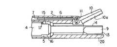
前記伝達ロッド4の先端部はこの部分以外の部分の径より僅かに小径に形成されており、その先端部の最先端部分は保護シース2の先端から突き出す部分として処置部(部材)9を構成している。この保護シース2の先端から突き出す処置部9は前記把持部材10の把持パット10aに対置する。さらに、保護シース2の先端から突き出す処置部はその片面に生体組織を凝固させるための凝固面13を形成し、それと反対側に片面には生体組織を切開するための切開部14が設けられている。すなわち、図2において上面側には鈍的な丸い形状で凝固面13が形成されており、下面側には切開部14がナイフ状の鋭利なエッジとして形成されている。
【0015】
前記伝達ロッド4において、小径の先端部から段差を介して連続する太径の部分の先端部分で、その上下各部分にはそれぞれ平坦に切り欠いた係合部15,16が設けられている。前記保護シース2の伝達ロッド用挿通孔5にはこれを左右に横切る状態で設けられた少なくとも1本の整位用ピン17がその挿通孔5の比較的上部に位置して設けられており、この整位用ピン17に対して前記係合部15,16を係合するようになっている。ここでは1本の整位用ピン17が上側に位置して設置されており、伝達ロッド4を回転させて上側に向けた係合部15,16のみが整位用ピン17に係合する。そして、整位用ピン17に係合する係合部15,16に対応する前記凝固面13または切開部14が上側に向き、把持部材10の把持パット10aに対置するようになる。
【0016】
さらに、前記保護シース2の先端部にはこれの下端部を延長して前記超音波プローブ3の処置部9と同程度に突出した片状のガード部材20が一体に連続して設けられている。このガード部材20は保護シース2から突き出す処置部9の下側の部分にのみ位置してこれに対置する切開部14の鋭利な刃の部分を覆うようになっている。つまり、前記シースから外部に露出する前記処置部9に対して前記把持部材10とは反対側に位置してその処置部9の、処置対象の生体組織に対面しない部分の面を覆う。
【0017】
一方、操作部1には保護シース2に超音波プローブ3の伝達ロッド4を挿入して装着したとき、その超音波プローブ3を係着する抜止めレバー21が設けられている。抜止めレバー21を図1(a)で示すように立ち上げると、超音波プローブ3の出し入れが可能となり、図1(b)で示すように倒すと、超音波プローブ3の抜き出しが不可能となる。
【0018】
(作用)
次に、超音波ハンドピースの使用上の作用について説明する。まず、その使用目的に応じて伝達ロッド4の処置部9の向きを選定する。図2は生体組織を凝固する場合の状態であり、伝達ロッド4の先端に構成した処置部9における凝固面13が上側に向き、把持部材10に対置している。生体組織を切開する場合には伝達ロッド4を180゜回転して処置部9の切開部14を上側へ向け、把持部材10に対置する状態にする。
【0019】
これらの状態の切り換えは次のようにして行うことができる。すなわち、抜止めレバー21を図1(a)で示すように立ち上げて、伝達ロッド4を後退させ、整位用ピン17に係合していた係合部15,16の一方をその整位用ピン17から退避させる。すると、伝達ロッド4が自由に回転できるようになり、そこで、図1(a)で示すように超音波プローブ3の全体を180゜回転すれば、処置部9の向きが反転し、凝固面13と切開部14の向きが入れ替る。この後、伝達ロッド4を前進させて上側の係合部15を整位用ピン17に係合し、伝達ロッド4の向きを整位してその位置に固定する。抜止めレバー21を図1(b)で示すように倒して操作部1に超音波プローブ3を固定する。
【0020】
次に、生体組織を凝固する場合についての作用を説明する。直接または腹腔鏡下手術のときはトラカールや内視鏡等を利用して体腔内に導入し、図3に示すように把持部材10と凝固面13との間で処置対象の生体組織25を挟み込む。その後、超音波を発振させ、その振動を伝達ロッド4を通じて処置部9へ伝達する。把持部材10と超音波振動をしている処置部9における凝固面13で挟まれた処置対象の生体組織25の部分は振動による摩擦熱で焼灼され、凝固処理がなされる。
【0021】
この凝固処理の際、凝固面13とは反対側にある切開部14はガード部材20によって覆われ、正常な生体組織26には接触しないように保護される。
以上により術者の見えないところで、正常な生体組織26が焼灼されてしまうことがなく、また、超音波発振していないときでも、鋭利な切開部14が生体組織に触れてその生体組織を傷付ける虞はない。従って、使い易い超音波ハンドピースを提供できる。
【0022】
<第2実施形態>
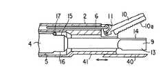
図4を参照して本発明の第2実施形態を説明する。この第2実施形態は前述した第1実施形態と基本的には同じであるが、保護シース2の先端はこれに前述したガード部材20を設けることなく端面がカットされており、その先端は超音波プローブ3の処置部9の根元部分くらいまでの長さしかない。
【0023】
一方、前記保護シース2とは別にその保護シース2の周囲には外シース30が被嵌して設けられており、その外シース30の先端部には超音波プローブ3の先端部9における処置部の先端面まで突出した前記同様の機能を持つガード部材31が前記同様に設けられている。
【0024】
ここで、外シース30と保護シース2とは嵌合されているため、互いに分離することができる。つまり、保護シース2から外シース30を取り外すことができる。これによりガード部材31が必要な観察困難な個所で使用する場合には外シース30を取り付けた状態で使用し、視野が良好で特にガード部材31が不要な場合にはその外シース30を取り外した状態で処置することができる。ガード部材31の使用の有無を術者が選択し、それぞれ必要最小限の最適な状態で作業を行うことができる。
【0025】
<第3実施形態>
図5を参照して、本発明の第3実施形態を説明する。この実施形態では保護シース2の先端部の下面部分に、前記同様の機能を持つガード部材40を保護シース2の長手軸方向に沿ってスライド自在に取着したものである。そのスライド機構としては例えばガード部材40に設けられた凸部がスライド自在に係合する凹部41を有したスライド係合部を設ける。
【0026】
ガード部材40は図5中の矢印で示すように保護シース2上をその後前後方向へスライド自在であり、使用する場合には前進させて突き出し、使用しない場合には後退させて保護シース2の下面領域に退避させておく。また、各位置に仮固定はガード部材40とこれが係合する凹部41との間の摩擦力やクリック係合等であってもよいが、他の固定手段を設けてもよい。
【0027】
従って、術者の好みに応じてガード部材40を付けたり付けなくしたりすることができる。しかも、スライドするだけなので、第2実施形態のように外シースを外したりする手間がなく、その切換えの作業が容易である。
【0028】
なお、スライドだけでなく、ガード部材40を保護シース2から取り外してしまうことも勿論可能である。
<第4実施形態>
図6を参照して、本発明の第4実施形態を説明する。この実施形態は超音波切開凝固装置のシステムにおいて、超音波ハンドピースの超音波発振動作を、超音波ハンドピースの操作部1に設けたハンドスイッチ51と、これとは別に設けたフットスイッチ52の両方で操作できるようにしたものである。超音波発振信号源を含む装置本体53には超音波プローブ3の超音波発振器が接続され、さらにハンドスイッチ51とフットスイッチ52が接続されている。ハンドスイッチ51とフットスイッチ52のいずれを用いても超音波発振動作のオンオフ操作を行うことができる。ハンドスイッチ51にすると、操作部1による鉗子操作と並列して行うことができる。超音波ハンドピースは他の各実施形態で述べるものと同様な構成になっている。
【0029】
<第5実施形態>
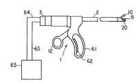
図7を参照して本発明の第5実施形態を説明する。この実施形態は超音波切開凝固装置のシステムにおいて、超音波発振動作のオンオフ操作を生体組織の凝固/切開の動作に対応させて的確に行おうとするものである。
【0030】
すなわち、超音波ハンドピースの操作部1には固定的に設けられた前ハンドル61と前述した開閉操作レバー12の一対の操作ハンドルが設けられている。後ハンドルとなる開閉操作レバー12には親指を掛けるようになっており、前ハンドル61には他の指を掛けてそれを握るようになっている。前ハンドル61において手で握られる部分にはある程度の圧力が掛かると導通する圧力スイッチ(センサ)62が設けられている。圧力スイッチ62からの信号は電源ケーブル63に一体的に包括された信号線64を通って超音波発振信号源を含む装置本体65に信号が送られ、その装置本体65においての振動発生制御手段により超音波発振動作のオンオフを行うようになっている。
【0031】
すなわち、前ハンドル61と開閉操作レバー12の一対の操作ハンドルでの操作で超音波ハンドピースの処置部9に対象組織を把持すると、ある程度の圧力が圧力スイッチ62に加わる。生体組織を把持後さらに握り込むことにより圧力スイッチ62がオン信号を発し、これにより超音波が発振され組織を凝固/切開することができる。処置後は手を離すか、または力をゆるめることにより自動的に発振動作がオフされる。これにより、より正確な力量を得ることができる。
【0032】
この実施形態によれば、必要なときのみ発振させることができ、フットスイッチやハンドスイッチ等を一々押す操作が不要となり、また、踏み間違い等もなくなり、より安全で確実に手術を行うことができる。また、余分なコード類がなくなるので、準備、片付けが容易になる。
【0033】
<第6実施形態>
図8(a)(b)を参照して、本発明の第6実施形態を説明する。この実施形態も超音波切開凝固装置のシステムにおいて、超音波発振動作のオンオフ操作を生体組織の凝固/切開の動作に対応させて的確に行おうとするものである。
【0034】
図8(a)(b)は前述したような超音波ハンドピースに組み込まれたスイッチ機構を模式的に示した説明図である。
すなわち、前述したように把持部材10は操作部1のハンドル操作によって開閉させられる。把持操作棒(操作部材)6は操作部1内において枢支ポイント71で、後ハンドルとしての開閉操作レバー12に接続される。開閉操作レバー12のアーム途中には枢支点72が設けられており、この枢支点72はスライド部材73に設けられている。スライド部材73は操作部1に設けられたガイド部74にスライド自在に収納され、通常はコイルばね75や板ばね等の弾性付勢手段によってガイド部74の末端まで押し付けられている。また、スライド部材73にはスイッチのオンオフ操作ボタン76がスライド部材73に対して枢支点72の反対側に位置して対向して設置されている。
【0035】
そこで、図8(a)で示すように、後ハンドルの開閉操作レバー12を前方の方向へ移動させると、操作棒6が前方へ移動し、把持部材10が閉じ、対象の生体組織77を超音波プローブ3の処置部9との間で把持し、その後、さらに力を入れていくと、図8(b)に示すように枢支点72がガイド部材73に沿ってコイルばね75を縮める方向に動き、スイッチのオンオフ操作ボタン76を押すことになる。これによりスイッチが操作され、超音波が発振し、対象組織を処置することができる。力をゆるめると、再び枢支点72が元に戻り、オンオフ操作ボタン76がオフの状態になる。
【0036】
これにより、必要なときのみ発振させることができ、フットスイッチやハンドスイッチ等を一々押す操作が不要となり、また、踏み間違い等もなくなり、より安全で確実に手術を行うことができる。また、余分なコード類がなくなるので、準備、片付けが容易になる。
【0037】
<第7実施形態>
図9を参照して、本発明の第7実施形態を説明する。この実施形態も超音波切開凝固装置のシステムにおいて、超音波発振動作のオンオフ操作を生体組織の凝固/切開の動作に対応させて的確に行おうとするものである。
【0038】
すなわち、この実施形態では前述したような超音波ハンドピースにおいての把持部材10に圧力センサ、例えば歪みゲージ81を貼り付けたものである。これによれば、把持力をより正確に検出することができる。把持力が加わると、その把持部材10が歪むため、その歪み量がある一定に達すると、その信号を受けて超音波を発振させる。
【0039】
また、把持部材10の把持パッド10a内またはその把持面10bに圧力センサを付けておくようにしてもよい。また、把持面10bに圧電部材を設けて圧力検知することも可能であり、このように直接に圧力を検知する構成にすれば、他の実施形態に比較して確実に把持状態を検出することができる。
【0040】
[付記]
(1)操作部と、この操作部に連結されたシースと、前記操作部側に設置された超音波振動子と、前記シースの先端部において外部に露出して設けられ生体組織に対して超音波振動を与えて処置を行う処置部材と、前記シース内に挿通され前記処置部材に前記超音波振動子からの超音波振動を伝達する振動伝達部材と、前記処置部材に対置してその処置部材との間で生体組織の把持及び開放を行う把持部材と、前記シース内に挿通され前記操作部の操作による動きを前記把持部材に伝達して把持部材に把持及び開放の動きを行わせる操作部材と、前記シースから外部に露出する前記処置部材に対して前記把持部材とは反対側に位置してその処置部材の処置対象の生体組織に対面しない部分の面を覆うガード部材とを具備したことを特徴とする超音波治療装置。
【0041】
(2)付記第1項において、前記処置部材は前記シース側に対して固定的に設置されていることを特徴とする超音波治療装置。
(3)付記第1項において、前記ガード部材は前記シースの先端部分を延長して一体的に形成したことを特徴とする超音波治療装置。
(4)付記第1項において、前記ガード部材は前記シースとは別体の部材で形成されていることを特徴とする超音波治療装置。
【0042】
(5)付記第1項において、前記ガード部材は前記シースとは別体の部材で形成され、前記シースの先端から選択的に必要な位置に設置されることを特徴とする超音波治療装置。
(6)付記第5項において、前記ガード部材は前記シースにスライド機構によりスライド自在に設けられていることを特徴とする超音波治療装置。
(7)付記第5項において、前記ガード部材は前記シースに対して着脱自在で、必要なときに前記シースの先端から選択的に必要な位置に設置されることを特徴とする超音波治療装置。
【0043】
(8)操作部と、この操作部に連結されたシースと、前記操作部側に設けられた超音波振動子と、前記シースの先端部において外部に露出して固定的に設けられ生体組織に対して超音波振動を与えて処置を行う処置部材と、前記シース内に挿通され前記処置部材に前記超音波振動子からの超音波振動を伝達する振動伝達部材と、前記処置部材に対置してこの処置部材との間で生体組織の把持及び開放を行う動きをする把持部材と、前記シース内に挿通され前記操作部の操作による動きを前記把持部材に伝達して把持部材に把持及び開放の動きを行わせる操作部材と、前記把持部材が生体組織を把持する際の把持力量が、所定の力量に達したことを検知する把持力量検知手段と、この把持力量検知手段からの出力結果に基づいて前記超音波振動子に振動を発生させる制御を行う振動発生制御手段とを具備したことを特徴とする超音波切開凝固装置。
【0044】
(9)付記第8項において、前記把持力量検知手段は前記操作部材に掛かる力量を検出することを特徴とする超音波切開凝固装置。
(10)付記第8項において、前記把持力量検知手段は前記操作部材を操作する操作レバーのグリップ部にグリップ力を検知するセンサを設けてなることを特徴とする超音波切開凝固装置。
(11)付記第8項において、前記把持力量検知手段は、前記操作部材に移動する支点を有し、この支点の移動量により前記把持部材が生体組織を把持する際の把持力量が、所定の力量に達したことを検知するスイッチ手段を設けたことを特徴とする超音波切開凝固装置。
【0045】
(12)請求項8において、前記把持力量検知手段は、前記把持部材に歪みセンサを設け、歪みセンサの歪み量によって生体組織を把持する際の把持力量が、所定の力量に達したことを検知する手段を構成したことを特徴とする超音波切開凝固装置。
(13)請求項8において、把持部材に圧力センサが設けられていることを特徴とする。
【0046】
【発明の効果】
以上説明したように本発明によれば、超音波振動をする処置部材が正常な生体組織に不要に接することを防止し、また、安全確認の確認作業が簡便化し、処置の操作性が高まり、一般的には安全な手術することができる超音波治療装置を提供することができる。
【図面の簡単な説明】
【図1】(a)(b)はそれぞれ第1実施形態に係る超音波ハンドピースの側面図。
【図2】第1実施形態に係る超音波ハンドピースの先端部付近の断面図。
【図3】第1実施形態に係る超音波ハンドピースの使用状態の説明図。
【図4】第2実施形態に係る超音波ハンドピースの先端部付近の断面図。
【図5】第3実施形態に係る超音波ハンドピースの先端部付近の断面図。
【図6】第4実施形態に係る超音波ハンドピースの概略的な説明図。
【図7】第5実施形態に係る超音波ハンドピースの概略的な説明図。
【図8】第6実施形態に係る超音波ハンドピースの概略的な説明図。
【図9】第7実施形態に係る超音波ハンドピースの先端部付近の断面図。
【図10】従来の超音波ハンドピースの先端部付近の断面図。
【符号の説明】
1…操作部、2…シース、3…超音波プローブ、4…伝達ロッド、6…把持操作棒、8…超音波発振器、9…処置部、10…把持部材、12…開閉操作レバー、20…ガード部材、25…生体組織、31…ガード部材、40…ガード部材。[0001]
BACKGROUND OF THE INVENTION
The present invention relates to an ultrasonic therapy apparatus that performs treatment such as incision or coagulation using ultrasonic vibration.
[0002]
[Prior art]
In recent years, endoscopes have been inserted into body cavities to observe organs in the body cavity and the like, and various treatments have been performed under observation with the endoscope.
As a method of performing treatment under endoscopic observation, living tissue is adsorbed or grasped, and ultrasonic vibration is applied to the adsorbed or grasped member to coagulate or excise the living tissue. It is already known to perform such treatment.
[0003]
For example, JP-A-1-232948 discloses a surgical excision forceps in which excision forceps can be efficiently excised by applying ultrasonic vibration to a tip excision portion provided with a fixed blade and a movable blade. It is shown.
[0004]
However, in the above-described prior art, only one of incision or coagulation treatment can be performed on a living tissue with one hand piece. For this reason, for example, when performing a combined treatment such as incising a living tissue and coagulating a necessary site, it is necessary to replace different handpieces. In order to solve such a problem, US Pat. No. 5,322,055 proposes an ultrasonic surgical instrument as shown in FIG.
In this ultrasonic surgical instrument, a gripping
[0005]
That is, when ultrasonically coagulating a living tissue, the
[0006]
[Problems to be solved by the invention]
In JP-A-1-23948, although both blades of the tip resection part vibrate, during actual laparoscopic surgery, they are observed with an endoscope, and the field of view is considerably limited. One of the blades cannot be seen.
If ultrasonic oscillation is performed in this state, the invisible part of the blade may come into contact with normal tissue and may cause burns due to frictional heat generated by ultrasonic vibration, and it is very troublesome to prevent this from occurring. Confirmation work is necessary, which is a cause of lowering operability.
[0007]
On the other hand, in the ultrasonic surgical instrument of US Pat. No. 5,322,055, since the gripping member does not vibrate directly, there is no problem that the gripping member is burned by frictional heat due to ultrasonic vibration. However, the same problem as described above occurs depending on the method of use.
Further, in the latter ultrasonic surgical instrument, one of the
[0008]
The present invention has been made paying attention to the above-mentioned problems, and the purpose thereof is to prevent the treatment member that performs ultrasonic vibration from unnecessarily coming into contact with a normal living tissue, and to confirm the safety confirmation. An object of the present invention is to provide an ultrasonic therapy apparatus which can be simplified, enhance the operability of the treatment, and can generally perform a safe operation.
[0009]
[Means for Solving the Problems]
The invention according to claim 1 is connected to the ultrasonic transducer, an elongated sheath as a protective member, an ultrasonic transducer provided on the proximal side of the sheath so as to be capable of generating ultrasonic vibrations, and A vibration transmitting member having a treatment member exposed to the outside from the distal end portion of the sheath so that the ultrasonic vibration can be applied to the living tissue, and the opening and closing of the treatment member so that the treatment member can be opened and closed. A gripping member provided facing the treatment member, and a guard member provided so as to protrude from the distal end of the sheath so as to cover the treatment member on the side opposite to the gripping member with respect to the treatment member, An ultrasonic therapy apparatus characterized by comprising:
According to a second aspect of the present invention, there is provided an elongated first sheath as a protective member, an ultrasonic transducer provided on the proximal side of the first sheath so as to be capable of generating ultrasonic vibration, A vibration transmitting member provided with a treatment member that is connected to a sound wave oscillator and is exposed to the outside from a distal end portion of the first sheath so that the ultrasonic vibration can be applied to a living tissue; So that it can be opened and closed. A gripping member provided facing the treatment member; a second sheath provided detachably with respect to the first sheath; and a treatment member comprising a hollow portion through which the first sheath can be inserted. The guard is provided at the distal end of the second sheath so as to cover the treatment member on the opposite side of the gripping member, and protrudes in the distal direction from the distal end of the first sheath. And an ultrasonic therapy apparatus.
[0010]
DETAILED DESCRIPTION OF THE INVENTION
<First Embodiment>
A first embodiment of the present invention will be described with reference to FIGS. This embodiment is an example of an ultrasonic handpiece according to an ultrasonic incision and coagulation apparatus that selectively performs incision and coagulation using ultrasonic vibration.
[0011]
(Constitution)
FIG. 1 shows the overall appearance of the ultrasonic handpiece. In FIG. 1, reference numeral 1 denotes an operating portion, and a
[0012]
The
[0013]
A gripping member (jaw) 10 with a gripping pad is rotatably attached to the tip of the
[0014]
The distal end portion of the
[0015]
In the
[0016]
Further, a piece-
[0017]
On the other hand, when the
[0018]
(Function)
Next, the operation of the ultrasonic handpiece will be described. First, the direction of the
[0019]
Switching between these states can be performed as follows. That is, the retaining
[0020]
Next, the effect | action about the case where a biological tissue is coagulated is demonstrated. In direct or laparoscopic surgery, the body is introduced into the body cavity using a trocar or endoscope, and the
[0021]
During this coagulation treatment, the
As described above, the
[0022]
Second Embodiment
A second embodiment of the present invention will be described with reference to FIG. The second embodiment is basically the same as the first embodiment described above, but the end of the
[0023]
On the other hand, apart from the
[0024]
Here, since the
[0025]
<Third Embodiment>
A third embodiment of the present invention will be described with reference to FIG. In this embodiment, a
[0026]
The
[0027]
Therefore, the
[0028]
Of course, it is possible to remove the
<Fourth embodiment>
A fourth embodiment of the present invention will be described with reference to FIG. In the ultrasonic incision coagulation apparatus system according to this embodiment, an ultrasonic oscillation operation of an ultrasonic handpiece is performed by a
[0029]
<Fifth Embodiment>
A fifth embodiment of the present invention will be described with reference to FIG. In this embodiment, in an ultrasonic incision and coagulation apparatus system, an on / off operation of an ultrasonic oscillation operation is accurately performed in accordance with a coagulation / incision operation of a living tissue.
[0030]
That is, the operation unit 1 of the ultrasonic handpiece is provided with a
[0031]
That is, when the target tissue is grasped by the
[0032]
According to this embodiment, it is possible to oscillate only when necessary, and there is no need to press a foot switch or a hand switch one by one, and there is no mistake in stepping, so that a safer and more reliable operation can be performed. . Also, since there are no extra codes, preparation and cleanup are easy.
[0033]
<Sixth Embodiment>
With reference to FIGS. 8A and 8B, a sixth embodiment of the present invention will be described. This embodiment is also intended to accurately perform an on / off operation of the ultrasonic oscillation operation corresponding to the coagulation / incision operation of the living tissue in the system of the ultrasonic incision coagulation apparatus.
[0034]
FIGS. 8A and 8B are explanatory views schematically showing a switch mechanism incorporated in the ultrasonic handpiece as described above.
That is, as described above, the gripping
[0035]
Therefore, as shown in FIG. 8A, when the opening /
[0036]
As a result, it is possible to oscillate only when necessary, eliminating the need to press a foot switch, a hand switch or the like one by one, eliminating mistakes in stepping, etc., and performing a safer and more reliable operation. Also, since there are no extra codes, preparation and cleanup are easy.
[0037]
<Seventh embodiment>
A seventh embodiment of the present invention will be described with reference to FIG. This embodiment is also intended to accurately perform an on / off operation of the ultrasonic oscillation operation corresponding to the coagulation / incision operation of the living tissue in the system of the ultrasonic incision coagulation apparatus.
[0038]
That is, in this embodiment, a pressure sensor such as a strain gauge 81 is attached to the gripping
[0039]
Further, a pressure sensor may be attached in the
[0040]
[Appendix]
(1) An operation unit, a sheath connected to the operation unit, an ultrasonic transducer installed on the operation unit side, and exposed to the outside at the distal end portion of the sheath. A treatment member that performs treatment by applying sonic vibration, a vibration transmission member that is inserted into the sheath and transmits ultrasonic vibration from the ultrasonic transducer to the treatment member, and a treatment member that faces the treatment member A gripping member that grips and releases the living tissue between the control member and an operation member that is inserted into the sheath and that transmits the movement caused by the operation of the operation unit to the gripping member to cause the gripping member to perform the gripping and opening movement And a guard member that covers the surface of the treatment member that is exposed to the outside from the sheath and that is located on the opposite side of the grasping member and does not face the treatment target living tissue of the treatment member. Characterized by Sound wave therapy device.
[0041]
(2) The ultrasonic treatment apparatus according to item 1, wherein the treatment member is fixedly installed on the sheath side.
(3) The ultrasonic therapy apparatus according to item 1, wherein the guard member is integrally formed by extending a distal end portion of the sheath.
(4) The ultrasonic therapy apparatus according to item 1, wherein the guard member is formed of a member separate from the sheath.
[0042]
(5) The ultrasonic therapy apparatus according to item 1, wherein the guard member is formed of a member separate from the sheath and is selectively installed at a necessary position from the distal end of the sheath.
(6) The ultrasonic therapy apparatus according to
(7) The ultrasonic therapy apparatus according to
[0043]
(8) An operation unit, a sheath connected to the operation unit, an ultrasonic transducer provided on the operation unit side, and exposed to the outside at a distal end portion of the sheath and fixedly provided on a living tissue A treatment member that performs treatment by applying ultrasonic vibration to the treatment, a vibration transmission member that is inserted into the sheath and transmits ultrasonic vibration from the ultrasonic transducer to the treatment member, and a treatment member A grasping member that moves to grasp and release a living tissue with the treatment member, and a movement that is inserted into the sheath and is operated by the operation unit is transmitted to the grasping member to be grasped and released by the grasping member. Based on an operation member that causes movement, a gripping force amount detection unit that detects that a gripping force amount when the gripping member grips a living tissue has reached a predetermined force amount, and an output result from the gripping force amount detection unit The ultrasonic vibration Ultrasonic dissection coagulation apparatus characterized by comprising a vibration generation control means for controlling to generate a vibration to.
[0044]
(9) The ultrasonic incision and coagulation apparatus according to
(10) The ultrasonic incision and coagulation apparatus according to
(11) In the
[0045]
(12) In
(13) In
[0046]
【The invention's effect】
As described above, according to the present invention, it is possible to prevent the treatment member that performs ultrasonic vibration from coming into unnecessary contact with normal living tissue, simplify the confirmation work of safety confirmation, and improve the operability of the treatment. In general, it is possible to provide an ultrasonic treatment apparatus capable of performing a safe operation.
[Brief description of the drawings]
1A and 1B are side views of an ultrasonic handpiece according to a first embodiment, respectively.
FIG. 2 is a cross-sectional view of the vicinity of the distal end portion of the ultrasonic handpiece according to the first embodiment.
FIG. 3 is an explanatory diagram of a usage state of the ultrasonic handpiece according to the first embodiment.
FIG. 4 is a cross-sectional view of the vicinity of a distal end portion of an ultrasonic handpiece according to a second embodiment.
FIG. 5 is a cross-sectional view of the vicinity of the tip of an ultrasonic handpiece according to a third embodiment.
FIG. 6 is a schematic explanatory view of an ultrasonic handpiece according to a fourth embodiment.
FIG. 7 is a schematic explanatory view of an ultrasonic handpiece according to a fifth embodiment.
FIG. 8 is a schematic explanatory view of an ultrasonic handpiece according to a sixth embodiment.
FIG. 9 is a cross-sectional view of the vicinity of the tip of an ultrasonic handpiece according to a seventh embodiment.
FIG. 10 is a cross-sectional view of the vicinity of the tip of a conventional ultrasonic handpiece.
[Explanation of symbols]
DESCRIPTION OF SYMBOLS 1 ... Operation part, 2 ... Sheath, 3 ... Ultrasonic probe, 4 ... Transmission rod, 6 ... Gripping operation rod, 8 ... Ultrasonic oscillator, 9 ... Treatment part, 10 ... Gripping member, 12 ... Opening / closing operation lever, 20 ... Guard member, 25 ... living tissue, 31 ... guard member, 40 ... guard member.
Claims (2)
Translated fromJapanese超音波振動を発生可能となるように前記シースの手元側に設けられた超音波振動子と、
前記超音波振動子に接続され、生体組織に前記超音波振動を付与可能となるように、前記シースの先端部から外に露出する処置部材を備えた振動伝達部材と、
前記処置部材に対して開閉可能となるように、前記処置部材に面して設けられた把持部材と、
前記処置部材に対して前記把持部材とは反対側でその処置部材を覆うように、前記シースの先端部から突き出して設けられたガード部材と、
を具備したことを特徴とする超音波治療装置。An elongated sheath as a protective member;
An ultrasonic transducer provided on the proximal side of the sheath so that ultrasonic vibration can be generated;
A vibration transmitting member that is connected to the ultrasonic transducer and includes a treatment member exposed to the outside from the distal end portion of the sheath so that the ultrasonic vibration can be applied to the living tissue;
A gripping member provided facing the treatment member so as to be openable and closable with respect to the treatment member;
A guard member protruding from the distal end of the sheath so as to cover the treatment member on the opposite side of the grasping member with respect to the treatment member;
An ultrasonic therapy apparatus comprising:
超音波振動を発生可能となるように前記第1のシースの手元側に設けられた超音波振動子と、
前記超音波振動子に接続され、生体組織に前記超音波振動を付与可能となるように、前記第1のシースの先端部から外に露出する処置部材を備えた振動伝達部材と、
前記処置部材に対置して開閉可能となるように.前記処置部材に面して設けられた把持部材と、
前記第1のシースを挿通可能な中空部を備え、前記第1のシースに対し着脱可能に設けられた第2のシースと、
前記処置部材に対して前記把持部材とは反対側でその処置部材を覆うように、前記第2のシースの先端部に設けられ、前記第1のシースの先端部よりも先端方向に突き出して設けられたガード部材と、
を具備したことを特徴とする超音波治療装置。A slender first sheath as a protective member;
An ultrasonic vibrator provided on the proximal side of the first sheath so as to be able to generate ultrasonic vibrations;
A vibration transmitting member that is connected to the ultrasonic transducer and includes a treatment member that is exposed from a distal end portion of the first sheath so that the ultrasonic vibration can be applied to a living tissue;
It can be opened and closed facing the treatment member. A gripping member provided facing the treatment member;
A second sheath provided with a hollow portion through which the first sheath can be inserted, and detachably provided with respect to the first sheath;
Provided at the distal end of the second sheath so as to cover the treatment member on the opposite side of the grasping member with respect to the treatment member, and projecting in the distal direction from the distal end of the first sheath Guard member made,
An ultrasonic therapy apparatus comprising:
Priority Applications (5)
| Application Number | Priority Date | Filing Date | Title |
|---|---|---|---|
| JP25999095AJP3628771B2 (en) | 1995-10-06 | 1995-10-06 | Ultrasonic therapy device |
| US09/353,652US6669690B1 (en) | 1995-04-06 | 1999-07-15 | Ultrasound treatment system |
| US10/650,759US7780659B2 (en) | 1995-04-06 | 2003-08-29 | Ultrasound treatment system |
| US12/801,887US8672935B2 (en) | 1995-04-06 | 2010-06-30 | Ultrasound treatment system |
| US12/801,886US8574228B2 (en) | 1995-04-06 | 2010-06-30 | Ultrasound treatment system |
Applications Claiming Priority (1)
| Application Number | Priority Date | Filing Date | Title |
|---|---|---|---|
| JP25999095AJP3628771B2 (en) | 1995-10-06 | 1995-10-06 | Ultrasonic therapy device |
Publications (2)
| Publication Number | Publication Date |
|---|---|
| JPH0998979A JPH0998979A (en) | 1997-04-15 |
| JP3628771B2true JP3628771B2 (en) | 2005-03-16 |
Family
ID=17341761
Family Applications (1)
| Application Number | Title | Priority Date | Filing Date |
|---|---|---|---|
| JP25999095AExpired - Fee RelatedJP3628771B2 (en) | 1995-04-06 | 1995-10-06 | Ultrasonic therapy device |
Country Status (1)
| Country | Link |
|---|---|
| JP (1) | JP3628771B2 (en) |
Families Citing this family (12)
| Publication number | Priority date | Publication date | Assignee | Title |
|---|---|---|---|---|
| JPH11178833A (en)* | 1997-12-24 | 1999-07-06 | Olympus Optical Co Ltd | Ultrasonic treatment implement |
| US6569178B1 (en) | 1999-03-09 | 2003-05-27 | Olympus Optical Co., Ltd. | Ultrasonic coagulating/cutting apparatus |
| JP3270413B2 (en)* | 1999-03-09 | 2002-04-02 | オリンパス光学工業株式会社 | Ultrasonic coagulation incision device |
| JP3270415B2 (en)* | 1999-03-11 | 2002-04-02 | オリンパス光学工業株式会社 | Ultrasonic coagulation incision device |
| JP4285841B2 (en)* | 1999-07-09 | 2009-06-24 | オリンパス株式会社 | Ultrasonic treatment device |
| JP4109096B2 (en) | 2002-01-11 | 2008-06-25 | オリンパス株式会社 | Ultrasonic treatment device |
| JP2006288431A (en)* | 2005-04-05 | 2006-10-26 | Olympus Medical Systems Corp | Ultrasonic surgical device |
| US9782214B2 (en)* | 2010-11-05 | 2017-10-10 | Ethicon Llc | Surgical instrument with sensor and powered control |
| JP6419847B2 (en)* | 2014-12-26 | 2018-11-07 | オリンパス株式会社 | Treatment instrument with detector |
| WO2016163450A1 (en) | 2015-04-10 | 2016-10-13 | オリンパス株式会社 | Medical device |
| KR102143070B1 (en)* | 2018-09-20 | 2020-08-10 | 연세대학교 산학협력단 | Endoscope surgery device |
| EP4595906A1 (en)* | 2022-09-30 | 2025-08-06 | FUJIFILM Corporation | Surgical treatment device |
- 1995
- 1995-10-06JPJP25999095Apatent/JP3628771B2/ennot_activeExpired - Fee Related
Also Published As
| Publication number | Publication date |
|---|---|
| JPH0998979A (en) | 1997-04-15 |
Similar Documents
| Publication | Publication Date | Title |
|---|---|---|
| JP3686117B2 (en) | Ultrasonic incision coagulator | |
| JP4700715B2 (en) | Energy treatment tool | |
| EP3364896B1 (en) | Surgical instrument with dual mode end effector and modular clamp arm assembly | |
| EP2583633B1 (en) | Ultrasonic device for cutting and coagulating | |
| JP5583637B2 (en) | Manual ultrasonic instrument | |
| JP4489281B2 (en) | Active load control of ultrasonic surgical devices | |
| JP4402629B2 (en) | Ultrasonic coagulation and incision device | |
| JP4879966B2 (en) | Coagulation and incision device | |
| US20070055228A1 (en) | Ultrasonic scalpel device | |
| US20070173872A1 (en) | Surgical instrument for cutting and coagulating patient tissue | |
| JP2009525106A (en) | Ultrasonic cutting equipment | |
| JP3628771B2 (en) | Ultrasonic therapy device | |
| JP2001029353A (en) | Ultrasonic treating device | |
| JP2001190564A (en) | Medical treatment instrument | |
| JP2000312682A (en) | Ultrasonic treatment tool | |
| JP3354032B2 (en) | Surgical forceps and ultrasonic coagulation and incision device | |
| KR20210023786A (en) | laparoscopic instrument | |
| JP2592487B2 (en) | Surgical resection forceps | |
| JPH08275949A (en) | Ultrasonic dissecting and coagulating device | |
| JP3270413B2 (en) | Ultrasonic coagulation incision device | |
| JP3709226B2 (en) | Ultrasonic coagulation and incision device | |
| JPH0938099A (en) | Ultrasonic incision/tissu coagulation device | |
| JP2001170070A (en) | Medical treatment instrument | |
| JP3270415B2 (en) | Ultrasonic coagulation incision device | |
| EP3838190B1 (en) | Passive dissection features for ultrasonic surgical instrument |
Legal Events
| Date | Code | Title | Description |
|---|---|---|---|
| A131 | Notification of reasons for refusal | Free format text:JAPANESE INTERMEDIATE CODE: A131 Effective date:20040713 | |
| A521 | Written amendment | Free format text:JAPANESE INTERMEDIATE CODE: A523 Effective date:20040908 | |
| TRDD | Decision of grant or rejection written | ||
| A01 | Written decision to grant a patent or to grant a registration (utility model) | Free format text:JAPANESE INTERMEDIATE CODE: A01 Effective date:20041124 | |
| A61 | First payment of annual fees (during grant procedure) | Free format text:JAPANESE INTERMEDIATE CODE: A61 Effective date:20041209 | |
| FPAY | Renewal fee payment (event date is renewal date of database) | Free format text:PAYMENT UNTIL: 20081217 Year of fee payment:4 | |
| FPAY | Renewal fee payment (event date is renewal date of database) | Free format text:PAYMENT UNTIL: 20081217 Year of fee payment:4 | |
| FPAY | Renewal fee payment (event date is renewal date of database) | Free format text:PAYMENT UNTIL: 20091217 Year of fee payment:5 | |
| FPAY | Renewal fee payment (event date is renewal date of database) | Free format text:PAYMENT UNTIL: 20101217 Year of fee payment:6 | |
| FPAY | Renewal fee payment (event date is renewal date of database) | Free format text:PAYMENT UNTIL: 20111217 Year of fee payment:7 | |
| FPAY | Renewal fee payment (event date is renewal date of database) | Free format text:PAYMENT UNTIL: 20111217 Year of fee payment:7 | |
| FPAY | Renewal fee payment (event date is renewal date of database) | Free format text:PAYMENT UNTIL: 20121217 Year of fee payment:8 | |
| LAPS | Cancellation because of no payment of annual fees |