JP3628742B2 - Medical manipulator - Google Patents
Medical manipulatorDownload PDFInfo
- Publication number
- JP3628742B2 JP3628742B2JP03388295AJP3388295AJP3628742B2JP 3628742 B2JP3628742 B2JP 3628742B2JP 03388295 AJP03388295 AJP 03388295AJP 3388295 AJP3388295 AJP 3388295AJP 3628742 B2JP3628742 B2JP 3628742B2
- Authority
- JP
- Japan
- Prior art keywords
- bending
- endoscope
- arm
- manipulator
- treatment
- Prior art date
- Legal status (The legal status is an assumption and is not a legal conclusion. Google has not performed a legal analysis and makes no representation as to the accuracy of the status listed.)
- Expired - Fee Related
Links
- 238000005452bendingMethods0.000claimsdescription98
- 238000003780insertionMethods0.000claimsdescription25
- 230000037431insertionEffects0.000claimsdescription25
- WABPQHHGFIMREM-UHFFFAOYSA-Nlead(0)Chemical compound[Pb]WABPQHHGFIMREM-UHFFFAOYSA-N0.000description6
- 230000000007visual effectEffects0.000description6
- 230000000694effectsEffects0.000description5
- 230000007935neutral effectEffects0.000description4
- 238000010586diagramMethods0.000description3
- 238000005286illuminationMethods0.000description3
- 238000002674endoscopic surgeryMethods0.000description2
- 238000000034methodMethods0.000description2
- 210000003815abdominal wallAnatomy0.000description1
- 230000004323axial lengthEffects0.000description1
- 239000003638chemical reducing agentSubstances0.000description1
- 238000002192cholecystectomyMethods0.000description1
- 210000004072lungAnatomy0.000description1
- 238000001356surgical procedureMethods0.000description1
- 210000000707wristAnatomy0.000description1
Images


Landscapes
- Surgical Instruments (AREA)
- Endoscopes (AREA)
Description
Translated fromJapanese【0001】
【産業上の利用分野】
本発明は、例えば、腹壁等の体壁に挿入孔を開け、この挿入孔を通じて内視鏡や処置具等の手術器械を体腔内に挿入することにより体腔内での様々な処置をマニピュレータ操作で行う経皮的内視鏡下外科手術において用いられる医療用マニピュレータに関する。
【0002】
【従来の技術】
この種の経皮的内視鏡下外科手術は大きな切開を要しない低侵襲な術式として、胆のう摘出手術や肺の一部を摘出除去する手術等で実際に行われている。この場合、内視鏡や処置具等の手術器械は経皮的に体腔内へ挿入されるのが普通であるが、別々のマニピュレータにそれらを個別的に搭載してその各マニピュレータに手術器械を操作し、体内部位の手術を術者に代って自由度の高い手術処置を行う手術用マニピュレータ装置が、特開昭6−30896号公報で提案されている。この手術用マニピュレータ装置は内視鏡を搭載した観察用マニピュレータと処置具を搭載した処置具用マニピュレータとが別々のものとして個別的に独立して設けられている。
【0003】
【発明が解決しようとする課題】
しかしながら、観察用マニピュレータや処置具用マニピュレータが別々のものとして個別的に独立して設けると、それらのマニピュレータのための経皮挿入孔を個々に多数開けなければならない。また、これらのスレーブマニピュレータを配置する向きの状態が異なることになるため、それらを操作するマスターアーム等の操作手段との整合させる調整が難しくなる等の問題が生じる。
【0004】
そこで、内視鏡や処置具等の手術器械を纏めて同じ挿入孔から体腔内に導入する方式が考えられる。すなわち、観察用の内視鏡の挿入部に隣接して処置具を並べて配置し、その内視鏡と処置具を湾曲操作することによって観察しながら自由度の高い手術の処置を行おうとするものである。
【0005】
しかし、内視鏡挿入部の湾曲部とこれに隣接する処置具の湾曲部をそれぞれ独立に動作させた場合において、内視鏡と処置具が干渉し、各動作を妨げるおそれがあり、それの操作性に問題があった。
【0006】
本発明は前記課題に着目してなされたもので、その目的とするところは内視鏡とマニピュレータとの干渉をなるべく避けるように動作可能でそれらの操作性を向上させることができる医療用マニピュレータを提供することにある。
【0007】
【課題を解決する手段および作用】
本発明は、挿入部に湾曲部を有した内視鏡と、この内視鏡の挿入部に沿って隣接され少なくとも1か所以上に湾曲部を有するアーム部を有した処置具とを備え、内視鏡の湾曲部と処置具の湾曲部を湾曲操作するようにした医療用マニピュレータにおいて、前記アーム部の最も基端部側の湾曲部の湾曲開始位置が、内視鏡の湾曲部の湾曲開始位置よりも基端部側にあることを特徴とする。
内視鏡挿入部に沿って配置された処置具のアーム部における最も基端部側の湾曲部の湾曲開始位置が、内視鏡の湾曲部の湾曲開始位置よりも基端部側に位置しているために、相互の干渉が起きにくい。また、例えば内視鏡の湾曲部を処置具のアーム部側に湾曲させる場合にも、そのアーム部の最も基端部側の湾曲部を内視鏡と同一方向に湾曲させることによって内視鏡の湾曲動作を阻害することがない。
【0008】
【実施例】
<第1の実施例>
図1ないし図3を参照して、本発明の第1の実施例を説明する。
(構成)
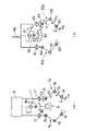
図1は医療用マニピュレータシステムの全体的な構成を概略的に示し、この医療用マニピュレータシステムはスレーブマニピュレータ1とマスターマニピュレータ2と両マニピュレータ1,2の関連動作を制御するための制御装置3とを備えている。
【0009】
前記スレーブマニピュレータ1は手術器械4とこれを支持する移動用マニピュレータ(ロボット)5を備える。手術器械4は移動用マニピュレータ5のアーム先端に対して着脱自在に搭載される。ここでの手術器械4としては立体式内視鏡6と一対の処置具(手段)としての一対の把持鉗子7a,7bとからなる。内視鏡6における挿入部8と一対の把持鉗子7a,7bは共通のシース9の内部に挿通されて同じ向きで配置されることにより一体的なユニットとして構成されている。すなわち一対の処置具7a,7bのアーム部10は内視鏡6の挿入部8に沿うとともにその挿入部8の左右位置に隣接して並んで配置されている。図1で示すように手術器械4のシース9は患者の体壁aに形成した挿通孔bを通じて体腔cの内部に挿入される。そして、前記手術器械4においての内視鏡6と把持鉗子7a,7bの先端部分は略同じ向きで体腔c内に突き出すように設置されるようになっている。
【0010】
ところで、前記内視鏡6はシース9の先端から突き出す挿入部8の先端側途中部分に自由度が2の湾曲部11を設けてなり、この湾曲部11は上下方向B1と左右方向B2の2方向に湾曲することによりその先端部12の向きを上下左右に変向するようになっている。
【0011】
前記内視鏡6の先端部12には左右一対の照明窓13と左右一対の観察窓14が設けられていて、この照明窓13から体腔c内の視野に照明光を照射する。そして、視野内を左右一対の観察窓14を通じて観察する。各観察窓14の内側にはCCD等の固体撮像素子がそれぞれ設置されており、各固体撮像素子は図示しないカメラコントロール回路によって駆動制御され、各観察窓14を通じて得られるそれぞれの視野を撮像する。
【0012】
また、左右の各把持鉗子7a,7bにおいて、シース9から突き出すアーム部10の途中でその長手方向の2箇所には湾曲部15,16を設けられ、基端側の第1の湾曲部15はC1方向に湾曲し、先端側の第2の湾曲部16はC2方向の湾曲が行われる。第1の湾曲部15が湾曲するC1方向と第2の湾曲部16が湾曲するC2方向とは通常の動作において同一の面内で互いに異なる向き、例えば直角な向きに湾曲するようになっている。また、シース9から突き出すアーム部10はその基端側に設けた回転部17によって自軸まわりのC3方向の回転も可能である。把持鉗子7a,7bのアーム部10の先端には処置作業用の一対の把持部材を回動可能に設けてなるグリッパ18が設けられている。各把持鉗子7a,7bは内視鏡6の挿入部8の軸に対して左右対称の構造をとり、同様の自由度を有している。
【0013】
処置用内視鏡6はその後端に駆動部19が設けられており、この駆動部19にはエンコーダ付き電磁モータ(図示しない)を備え、この駆動力を例えばワイヤー(図示しない)等によって、前記内視鏡6の湾曲部11の湾曲と把持鉗子7a,7bの湾曲部15,16の湾曲やそのアーム部10の回転、グリッパ18の開閉などの動作を駆動可能となっている。図2(a)はこのような手術器械4の各部における対偶関係を概略的に示すものである。
【0014】
図3は前記手術器械4において、シース9の先端から突き出す内視鏡6の挿入部8と把持鉗子7a,7bのアーム部10の部分をその上面側から見た図である。左右の各把持鉗子7a,7bにおいて、シース9から突き出すアーム部10の途中に設けられた湾曲部15,16のうち最も基端側に位置する湾曲部、ここでは湾曲部15の湾曲開始基端E1が内視鏡6における湾曲部11の湾曲開始基端E2よりも基端側にある。
【0015】
一方、前記移動用マニピュレータ5はベッドサイドに設置される支持機構であり、次に述べる如く、直動および回転の自由度を有する複数の軸を備えた多関節アーム構造で構成されている。つまり、これは基部20、水平旋回方向A1と垂直移動方向A2に動作する第1の動作軸21、この第1の動作軸21に対して水平方向A3に移動しかつ自軸周りの旋回方向A4に回転可能な第2の動作軸22とを備えてなり、さらに第2の動作軸22の先端にはその軸方向に直交した旋回方向A5とその旋回方向A5の軸に直交する軸まわりの旋回方向A6に回転可能ないわゆる手首機能を有する器具装着部材23が取り付けられている。この器具装着部材23に対して前記手術器械4のシース9を挿通し、その状態で手術器械4が支持されるようになっている。また、内視鏡6と一対の把持鉗子7a,7bからなる手術器械4のユニットは、移動用マニピュレータ5の先端に設けられた器具装着部材23に対して着脱可能に取り付けられている。この移動用マニピュレータ5の各軸には各方向に駆動する電磁モータ等のアクチュエータ(図示せず)とその回転角を検出するアブソリュート型エンコーダ(図示せず)および減速機(図示せず)がそれぞれ設けられている。
【0016】
一方、操作手段のマスターマニピュレータ2は移動用マスターアーム31と、これの先端に設けられたHMD用アーム32及び一対の処置手段操作用アーム33a,33bとによって構成されている。前記移動用マスターアーム31はリンク機構から構成されており、これは手術室の壁部や架台等の基台34に取り付けられ、その軸まわりのD1方向に回転する第1の軸部材36と、この第1の軸部材36の先端に関節37を介してD2方向に回転するように連結された第2の軸部材38と、この第2の軸部材38の先端に関節39を介してD3方向に回転するように連結された第3の軸部材40と、この第3の軸部材40の先端にD4方向に回転するように連結された装着用先端部材41を連結してなる。また、これらの各回転軸部分にはその回転角度を検出可能なようにエンコーダ42がそれぞれ取り付けられていて、これの検出データによって移動用マスターアーム31の先端の位置と向きとを検出可能になっている。
【0017】
前記HMD用アーム32は図2(b)で示すように2つの回転関節51,52を持つアーム53とこのアーム53の先端に固定された表示手段としてのHMD(ヘッドマウントディスプレイ)54とによって構成されている。このアーム53の回転関節51,52の回転方向E1,E2は互いに直交する向きにあり、それぞれにはエンコーダ55,56が設けられ、これによってHMD54の各回転方向E1,E2の回転量をそれぞれ検出可能になっている。
【0018】
また、一方の処置手段操作用アーム33aは3つの回転関節61,62,63を持つアーム64と、そのアーム64の先端に設けられた開閉可能な操作用グリッパ65によって構成されている。各回転関節61,62,63によってそれぞれF3,F1,F2の3つの方向への動きが可能になっている。また、3つの回転関節61,62,63と操作用グリッパ65にはそれぞれエンコーダが設けられ、その各回転関節61,62,63の回転角度やグリッパ65の開き角度がそれぞれ検出可能になっている。他方の処置手段操作用アーム33bは一方の処置手段用アーム33aに対して前記回転方向D4の回転軸に対して左右対称の構造をとり、これら両者の構成は同様であるため、この他方の処置手段操作用アーム33bについての説明を省略する。
【0019】
次に、前記スレーブマニピュレータ1とマスターマニピュレータ2の関連動作を制御するための制御装置3の構成について説明する。図1で示すように制御装置3は第1の制御装置71、第2の制御装置72、第3の制御装置73の部分からなり、制御対象の役割分担がなされている。まず、第1の制御装置71は移動用マスターアーム31の各エンコーダ42と電気的に接続され、そのエンコーダ42により回転角を検出することにより、移動用マスターアーム31の先端の位置を検出することができる。さらに第1の制御装置71は移動用マニピュレータ5の各電磁モータとこのモータに付いているエンコーダとも電気的に接続され、そのエンコーダで移動量を検出しながらそのモータを駆動し、移動用マニピュレータ5の先端の位置を決める。
【0020】
第2の制御装置72は、HMD用アーム32の各エンコーダ55,56と電気的に接続され、そのエンコーダ55,56の回転角を検出することにより、HMD54の向きを検出することができる。さらに第2の制御装置72は駆動部19内に設けられたモータと、このモータに付いているエンコーダと電気的に接続され、エンコーダで移動量を検出しながらそのモータを駆動できるので、指定された方向に処置用内視鏡6の挿入部8における湾曲部11を湾曲させることが可能である。
【0021】
また、第3の制御装置73は処置手段操作用アーム33a,33bの各エンコーダ74と電気的に接続され、このエンコーダ74により回転関節61,62,63と操作用グリッパ65の回転角を検出することにより、そのグリッパ65の向きと位置および開閉角度を検出することができる。さらに第3の制御装置73は駆動部19内に設けられた処置手段駆動用の各電磁モータと、このモータに付いているエンコーダと電気的に接続され、エンコーダで移動量を検出しながらそのモータを駆動できるので、処置手段としての把持鉗子7a,7bの位置と方向を決めることが可能である。
【0022】
また、前記内視鏡6の左のCCDの出力は図示しないビデオプロセッサによりTV信号に変換され、HMD54の左目の表示部の例えばLCDにその映像を表示することが可能になっている。また、右のCCDの出力は図示しないビデオプロセッサによりTV信号に変換され、HMD54の右目の表示部の例えばLCDにその映像を表示することが可能になっている。したがって、HMD54を装着した術者80は3次元的(立体的)に観察することが可能である。
(作用)
前述した医療用マニピュレータシステムを使用する際、まず、術者80はHMD54を頭にかぶり、左手で左のグリッパ65を持ち、右手で右のグリッパ65を持つ。このとき、術者80はHMD54により内視鏡6により得られた体腔内の映像を立体視することができる。
【0023】
ついで、術者80がその頭部の位置を変えると、その位置の変化を移動用マスターアーム31の各軸のエンコーダ42が検知し、第1の制御装置71はこれにより移動用マスターアーム31の先端位置を計算し、これに対応して内視鏡6における挿入部8の先端の位置が動くようにスレーブ側の移動用マニピュレータ5の各電磁モータを制御する。このとき、先端同士の座標系がそれぞれ対応するように制御を行う。
【0024】
また、術者80が首の向きを変えると、HMD用アーム32のエンコーダ55,56がこの動きを検出し、第2の制御装置72はHMD54の回転E1,E2と、内視鏡6の湾曲B1,B2が1対1に対応して動くように駆動部19内の図示しないエンコーダ付きモータを制御する。これらにより、処置用内視鏡6の位置及び向きが、術者80の頭の位置及び向きに対応して動くので、術者80はその頭の位置や向きを変えることによって患部に処置用内視鏡6を誘導し、様々な角度から患部を立体的に観察することが可能になる。
【0025】
次に、術者80が処置するときの動作を説明する。術者80が、例えば右の操作用グリッパ65の位置を変えたり、そのグリッパ65を開閉させたときの動きを処置手段操作用アーム33aの各関節61,62,63等に設けられたエンコーダ74が検知し、第3の制御装置73は右の処置手段操作用アーム33aの回転F1,F2,F3と、右の把持鉗子7aの回転C1、C2、C3が1対1に対応し、さらに操作用グリッパ65の開閉F4が、右の処置用グリッパ18の開閉C4の開閉量と一致して動作するように駆動部19内の図示しないエンコーダ付きモータを制御する。また、第3の制御装置73は左の処置手段操作用アーム33bと右の処置用把持鉗子7bも同様に1対1に対応して動くように、駆動部19内の図示しないエンコーダ付きモータを制御するが、右側と同様のため、これの説明は省略する。このように術者80の手の動きと処置具の動きが1対1に対応するので、術者80はHMD54の立体映像を観察しながら、例えば左の把持鉗子7bで患部を押さえ、右の把持鉗子7aで患部の剥離を行うなどの動作が可能である。
【0026】
次に、内視鏡6を湾曲するときの把持鉗子7a,7bのアーム部10の湾曲動作について図3を参照して説明する。3次元(立体)内視鏡6の湾曲部11が真直な同図3(a)の状態から同図3(b)の状態に左側に湾曲した場合、その湾曲向きにある把持鉗子7aのアーム部10における最も基端部側にある湾曲部15が同方向に湾曲するように制御される。このように内視鏡6を湾曲したとき、同時あるいは事前にその湾曲側に位置する把持鉗子7aのアーム部10が退避動作を行うため、内視鏡6の湾曲動作を把持鉗子7a,7bのアーム部10が妨げることがない。
(効果)
(1)このように3次元(立体)内視鏡6と把持鉗子7aのアーム部10との動作の干渉をなるべく避けることによって、操作性の良い医療用マニピュレータとすることができる。把持鉗子7a,7bの湾曲部15,16のうち最も基端側に位置するものの湾曲開始基端が内視鏡6における湾曲部11の湾曲開始基端よりも基端側にあるため、その退避動作が確実に行われる。
【0027】
(2)処置手段の把持鉗子7a,7bのアーム部10が、内視鏡6に沿って配設され、そのアーム部10の湾曲部15,16が内視鏡6を含む同一平面内において互いに異なるために、マニピュレータの動作範囲を内視鏡先端部近傍に展開することができ、内視鏡の視野範囲を広くカバーすることができる。
<第2の実施例>
図4を参照して、本発明の第2の実施例を説明する。
(構成)
この第2の実施例は前述した第1の実施例の医療用マニピュレータにおいての把持鉗子7a,7bのアーム部10の湾曲構造が相違し、これに関連しないものについては前述した第1の実施例のものと同様である。すなわち、各把持鉗子7a,7bはそのアーム部10の部分にそれぞれ3か所の湾曲部81,82,83を設けたものである。そして、最も基端部側にある湾曲部81の湾曲開始位置E1は内視鏡6の湾曲部11の湾曲開始位置E2よりも基端側に位置させてある。これによる作用効果は第1の実施例と略同じある。
<第3の実施例>
図5を参照して、本発明の第3の実施例を説明する。
(構成)
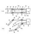
図5(a)はこの第3の実施例の構成をモデル化した図である。これは前述した第1の実施例の医療用マニピュレータにおいての把持鉗子7a,7bのアーム部10の湾曲構造が相違し、これに関連しないものについては前述した第1の実施例のものと同様である。すなわち、把持鉗子7a,7bの各アーム部10は第1の実施例と同様、2か所の湾曲部15,16を有するが、その湾曲部15,16によって区画されるアーム長L1より第2の湾曲部16よりグリッパ18までのアーム長L2を長くしたものである(L1 <L2 )。
【0028】
また、図5(a)において第1の湾曲部15は反時計まわり(同図中矢印A)、先端側の第2の湾曲部16は時計まわり(図中矢印B)に同一平面内で湾曲する制御が可能なようになっている。図5(b)は比較のためにL1 =L2 の場合の構成を示している。
(作用)
2つの湾曲部15,16が同一平面内で互いに異なる方向に湾曲動作を行うことによって、その把持鉗子7a,7bの動作範囲を内視鏡6の先端部近傍の視野領域内に大きく展開することができる。
また、L1 <L2 とすることによって、L1 ≧L2 である場合よりも把持鉗子7a,7bの動作範囲を広げることができる。
(効果)
処置手段としての把持鉗子7a,7bの動作範囲は内視鏡6の先端近傍に大きく展開させることによって、その内視鏡6の視野内を広くカバーすることができ、また広い動作範囲によって、操作性を向上させることができる。
<第4の実施例>
図6ないし図7を参照して、本発明の第4の実施例を説明する。
(構成)
この第4の実施例は前述した把持鉗子の一例を具体的に示すものである。この把持鉗子100はアーム部101の先端にグリップ部102を設けてなり、グリップ部102は回転軸103を中心に回転する2つの刃部(処置部材)104a,104bによって構成されている。2つの刃部104a,104bはその基端側に構成された図示しないリンク機構を介して同じく図示しない操作ワイヤに連結されている。そして、操作ワイヤを押し引きすることによりグリップ部102を開閉するようになっている。片側の刃部104aの背面にはその刃部104aに受ける力を検知するための触覚センサ105が取り付けられている。この触覚センサ105にはリード線106が接続されており、このリード線106を通じて触覚センサ105への電源の供給、触覚センサ105からの電気信号の取り出しを行うようになっている。
【0029】
前記把持鉗子100のアーム部101の途中に設けられる湾曲部107は次のように構成されている。すなわち、湾曲部107は複数の節輪108をアーム部101の軸方向に配列し、その隣接するもの同士をピン109で回転可能に接続し、全体的に湾曲するようになっている。隣接する各節輪108を枢支するピン109はアーム部101の中心軸から側方へ僅かに偏って配列されている。また、各節輪108は各ピン109を通る面より上面側の突当て端面は湾曲部107が真っ直ぐなとき互いに当たり、各ピン109を通る面より下側の突当て端面は湾曲部107が中心Pを中心として湾曲したときに互いに当たる。
【0030】
さらに節輪108の最先端のものにはその上下位置で上下の湾曲操作ワイヤ110a,110bの先端がそれぞれ固定されており、把持鉗子100の基端部側で、その湾曲操作ワイヤ110a,110bのどちらか一方を引くことによって、その引いた方へ節輪108に回転モーメントを与え、湾曲部107を湾曲するようになっている。図6(b)では下側の湾曲操作ワイヤ110bを引いたときの湾曲形状を示している。
【0031】
湾曲部107において各ピン109を通る面は軸方向長さの変化しない中立面112となるが、この中立面112上に前記リード線106が挿通されている。リード線106はアーム部101内を通って基端部側の図示しない制御装置へと結線されている。また、湾曲部107の湾曲回転中心Pは前記グリップ部102の回転軸103に直交するように配置して構成されている。
(作用)
触覚センサ105のリード線106が把持鉗子100のアーム部101内を通じて導かれる際、湾曲部107では中立面112を通っているため、湾曲部107が湾曲動作しても引張られて切れることがない。触覚センサ用配線の断線の可能性を低くすることによって、故障の少い安全性、経済性の高い医療用マニピュレータを提供できる。
【0032】
また、前述した実施例で示した場合と同様、例えば図7で示すように内視鏡115の隣りに把持鉗子100を配設して使用する場合、これの作用を説明する。図7(a)はその把持鉗子100にて、内視鏡115の観察下に生体組織116を把持している場面を後方上部から見た図である。この医療用マニピュレータでは湾曲部107の回転中心Pとグリップ部102の回転軸103とが直交しているために、生体組織116のまさに把持している部分を刃部104a,104bの間を通して観察可能である。なお、これとの比較のために示す図7(b)は湾曲部107の回転中心Pとグリップ部102の回転軸103とが平行になっている場合であるが、この場合、手前の刃部104aによってスコープ視野Sは妨げられ生体組織116の把持されている部分は見ることができず、把持状況を直接に把握しにくい。
(効果)
リード線106が断線することを予防しているために故障の少ない医療用マニピュレータとすることができる。また、グリップ部102によって把持されている部分がそのグリップ部102の部材の裏にならず、把持状態を常に見える観察能の高い医療用マニピュレータとすることができる。
[付記]
(1)挿入部に湾曲部を有した内視鏡と、この内視鏡の挿入部に沿って隣接され少なくとも1または2か所以上に湾曲部を有するアーム部を有した処置具とを備え、内視鏡の湾曲部と処置具の湾曲部を湾曲操作するようにした医療用マニピュレータにおいて、前記アーム部の最も基端部側の湾曲部の湾曲開始位置が、内視鏡の湾曲部の湾曲開始位置よりも基端部側にあることを特徴とする医療用マニピュレータ。
(2)第1項の医療用マニピュレータにおいて、内視鏡の湾曲部と処置具のアーム部における湾曲部がそれぞれ独立に動作が可能であることを特徴とする医療用マニピュレータ。
(3)第1項または第2項の医療用マニピュレータにおいて、処置具のアーム部における少なくとも2つの湾曲部が同一平面内において、互いに異なる方向に湾曲することを特徴とする医療用マニピュレータ。
(4)第1項、第2項または第3項の医療用マニピュレータにおいて、処置具が2つの、互いに同一の回転軸を中心に回転し、かみ合う複数の処置部材を持ち、前記処置部材の回転軸とその処置部材を支持するアーム部の複数の湾曲部の湾曲中心軸とが平行ではないことを特徴とする医療用マニピュレータ。
【0033】
(5)第1項ないし第4項のいずれかの医療用マニピュレータにおいて、処置具のアーム部における2つの湾曲部間のアーム部分の長さよりも、その湾曲部間よりも先端側に位置する湾曲部間のアーム部分の長さ及び最先端に位置する湾曲部とアーム部先端までのアーム部分の長さの少なくとも一方が長いことを特徴とする医療用マニピュレータ。
【0034】
(6)第1項ないし第5項のいずれかの医療用マニピュレータにおいて、処置具に配設された触覚センサへ電源を供給するための電源線と触覚センサからの電気信号を取出すための信号線を有し、電源線と信号線の少なくとも一方が、アーム部の湾曲部における湾曲中立面内に挿通されていることを特徴とする医療用マニピュレータ。
【0035】
【発明の効果】
以上説明したように本発明によれば、内視鏡挿入部の湾曲部とこれに隣接する処置具の湾曲部をそれぞれ湾曲させる場合において、その内視鏡と処置具が干渉を極力少なくでき、それらを動作させる際の操作性を向上させることができる。
【図面の簡単な説明】
【図1】本発明の第1の実施例に係る医療用マニピュレータシステムの全体的な構成の概略的説明図。
【図2】(a)は前記医療用マニピュレータシステムにおけるマスターマニピュレータの手術器械の対偶関係を示す説明図、(b)は前記医療用マニピュレータシステムにおけるHMD用アームと処置手段用アームの対偶関係を示す説明図。
【図3】前記医療用マニピュレータシステムにおけるマスターマニピュレータの手術器械の湾曲動作の説明図。
【図4】本発明の第2の実施例に係る医療用マニピュレータシステムにおけるマスターマニピュレータの手術器械の湾曲動作の説明図。
【図5】本発明の第3の実施例に係る医療用マニピュレータシステムにおけるマスターマニピュレータの手術器械の湾曲動作の説明図。
【図6】(a)は本発明の第4の実施例に係る医療用マニピュレータシステムにおける把持鉗子の上面図、(b)は同じくその側面から見た断面図。
【図7】前記本発明の第4の実施例に係る前記把持鉗子の使用状態の説明図。
【符号の説明】
1…スレーブマニピュレータ、2…マスターマニピュレータ、3…制御装置、4…手術器械、5…移動用マニピュレータ、6…内視鏡、7a,7b…把持鉗子、8…挿入部、10…アーム部、11…湾曲部、15,16…湾曲部、E1…湾曲開始基端、E2…湾曲開始基端。[0001]
[Industrial application fields]
In the present invention, for example, an insertion hole is formed in a body wall such as an abdominal wall, and a surgical instrument such as an endoscope or a treatment tool is inserted into the body cavity through the insertion hole. The present invention relates to a medical manipulator used in percutaneous endoscopic surgery.
[0002]
[Prior art]
This type of percutaneous endoscopic surgery is actually performed as a minimally invasive technique that does not require a large incision, such as a cholecystectomy or a surgery to remove and remove part of the lung. In this case, it is common for surgical instruments such as endoscopes and treatment tools to be inserted into the body cavity percutaneously. However, they are individually mounted on separate manipulators, and the surgical instruments are attached to the respective manipulators. Japanese Laid-Open Patent Publication No. 6-30896 proposes a surgical manipulator device that operates and performs a surgical operation on a body part with a high degree of freedom on behalf of an operator. In this surgical manipulator device, an observation manipulator equipped with an endoscope and a treatment tool manipulator equipped with a treatment tool are individually provided independently.
[0003]
[Problems to be solved by the invention]
However, if the observation manipulator and the treatment tool manipulator are individually provided independently, a large number of percutaneous insertion holes for these manipulators must be opened individually. In addition, since the orientation directions of the slave manipulators are different, there arises a problem that it is difficult to make adjustments with the operation means such as a master arm for operating them.
[0004]
Therefore, a method is considered in which surgical instruments such as an endoscope and a treatment tool are collectively introduced into the body cavity from the same insertion hole. That is, a treatment tool is arranged adjacent to the insertion portion of the observation endoscope, and a surgical operation with a high degree of freedom is performed while observing by bending the endoscope and the treatment tool. It is.
[0005]
However, when the bending portion of the endoscope insertion portion and the bending portion of the treatment tool adjacent to the endoscope insertion portion are operated independently, the endoscope and the treatment tool may interfere with each other, and each operation may be hindered. There was a problem with operability.
[0006]
The present invention has been made paying attention to the above-mentioned problems, and the purpose of the present invention is to provide a medical manipulator capable of operating so as to avoid interference between the endoscope and the manipulator as much as possible and improving the operability thereof. It is to provide.
[0007]
[Means and Actions to Solve the Problems]
The present invention includes an endoscope having a curved portion in an insertion portion, and a treatment instrument having an arm portion adjacent to the insertion portion of the endoscope and having a curved portion in at least one place, In the medical manipulator configured to bend the bending portion of the endoscope and the bending portion of the treatment instrument, the bending start position of the bending portion on the most proximal side of the arm portion is the bending of the bending portion of the endoscope. It is characterized in that it is on the base end side with respect to the starting position.
The bending start position of the bending portion on the most proximal end side in the arm portion of the treatment instrument arranged along the endoscope insertion portion is located closer to the proximal end portion than the bending start position of the bending portion of the endoscope. Therefore, mutual interference is difficult to occur. Further, for example, when the bending portion of the endoscope is bent toward the arm portion side of the treatment instrument, the bending portion on the most proximal end side of the arm portion is bent in the same direction as the endoscope. The bending movement is not hindered.
[0008]
【Example】
<First embodiment>
A first embodiment of the present invention will be described with reference to FIGS.
(Constitution)
FIG. 1 schematically shows an overall configuration of a medical manipulator system. This medical manipulator system includes a slave manipulator 1, a
[0009]
The slave manipulator 1 includes a surgical instrument 4 and a moving manipulator (robot) 5 that supports the surgical instrument 4. The surgical instrument 4 is detachably mounted on the arm tip of the moving
[0010]
By the way, the
[0011]
The
[0012]
Further, in each of the left and
[0013]
The
[0014]
FIG. 3 is a view of the surgical instrument 4 as seen from the upper surface side of the
[0015]
On the other hand, the moving
[0016]
On the other hand, the
[0017]
As shown in FIG. 2B, the
[0018]
One treatment means operation arm 33 a is constituted by an
[0019]
Next, the configuration of the
[0020]
The second control device 72 is electrically connected to the
[0021]
The
[0022]
The output of the left CCD of the
(Function)
When using the medical manipulator system described above, first, the
[0023]
Next, when the
[0024]
When the
[0025]
Next, the operation when the
[0026]
Next, the bending operation of the
(effect)
(1) Thus, it is possible to obtain a medical manipulator with good operability by avoiding interference between the operations of the three-dimensional (stereoscopic)
[0027]
(2) The
<Second embodiment>
A second embodiment of the present invention will be described with reference to FIG.
(Constitution)
This second embodiment is different in the bending structure of the
<Third embodiment>
A third embodiment of the present invention will be described with reference to FIG.
(Constitution)
FIG. 5A is a diagram modeling the configuration of the third embodiment. This is different in the bending structure of the
[0028]
In FIG. 5A, the
(Function)
By causing the two bending
L1 <L2 L1 ≧ L2 Therefore, the operating range of the grasping
(effect)
The operating range of the grasping
<Fourth embodiment>
A fourth embodiment of the present invention will be described with reference to FIGS.
(Constitution)
The fourth embodiment specifically shows an example of the aforementioned grasping forceps. This gripping
[0029]
The bending
[0030]
Further, the distal ends of the upper and lower bending operation wires 110a and 110b are fixed to the most advanced one of the node rings 108 at the upper and lower positions, respectively, and the bending operation wires 110a and 110b of the
[0031]
A surface passing through each
(Function)
When the
[0032]
Similar to the case shown in the above-described embodiment, for example, when the grasping
(effect)
Since the
[Appendix]
(1) An endoscope having a curved portion in the insertion portion, and a treatment instrument having an arm portion adjacent to the insertion portion of the endoscope and having a curved portion in at least one or more places. In the medical manipulator in which the bending portion of the endoscope and the bending portion of the treatment tool are bent, the bending start position of the bending portion closest to the proximal end of the arm portion is the position of the bending portion of the endoscope. A medical manipulator characterized by being on a proximal end side with respect to a bending start position.
(2) The medical manipulator according to the first item, wherein the bending portion of the endoscope and the bending portion of the arm portion of the treatment instrument can operate independently.
(3) The medical manipulator according to
(4) In the medical manipulator according to the first, second, or third item, the treatment instrument has two treatment members that rotate around the same rotation axis and mesh with each other, and the treatment member rotates. A medical manipulator characterized in that an axis and a bending central axis of a plurality of bending portions of an arm portion supporting the treatment member are not parallel.
[0033]
(5) In the medical manipulator according to any one of Items 1 to 4, the curvature is located on the distal side of the arm portion between the two bending portions in the arm portion of the treatment instrument, rather than between the bending portions. A medical manipulator characterized in that at least one of the length of the arm part between the parts and the length of the bending part located at the forefront and the length of the arm part up to the tip of the arm part are long.
[0034]
(6) In the medical manipulator according to any one of items 1 to 5, a power supply line for supplying power to a tactile sensor disposed in a treatment instrument and a signal line for taking out an electrical signal from the tactile sensor And at least one of the power line and the signal line is inserted into a curved neutral plane in the curved portion of the arm portion.
[0035]
【The invention's effect】
As described above, according to the present invention, when bending the bending portion of the endoscope insertion portion and the bending portion of the treatment tool adjacent thereto, the endoscope and the treatment tool can reduce interference as much as possible, The operability when operating them can be improved.
[Brief description of the drawings]
FIG. 1 is a schematic explanatory diagram of an overall configuration of a medical manipulator system according to a first embodiment of the present invention.
FIGS. 2A and 2B are explanatory views showing the even relationship between surgical instruments of a master manipulator in the medical manipulator system, and FIG. 2B shows the even relationship between an arm for HMD and an arm for treatment means in the medical manipulator system. Illustration.
FIG. 3 is an explanatory view of a bending operation of a surgical instrument of a master manipulator in the medical manipulator system.
FIG. 4 is an explanatory view of a bending operation of a surgical instrument of a master manipulator in a medical manipulator system according to a second embodiment of the present invention.
FIG. 5 is an explanatory view of a bending operation of a surgical instrument of a master manipulator in a medical manipulator system according to a third embodiment of the present invention.
6A is a top view of a grasping forceps in a medical manipulator system according to a fourth embodiment of the present invention, and FIG. 6B is a cross-sectional view seen from the side thereof.
FIG. 7 is an explanatory diagram of a usage state of the grasping forceps according to the fourth embodiment of the present invention.
[Explanation of symbols]
DESCRIPTION OF SYMBOLS 1 ... Slave manipulator, 2 ... Master manipulator, 3 ... Control apparatus, 4 ... Surgical instrument, 5 ... Movement manipulator, 6 ... Endoscope, 7a, 7b ... Grasping forceps, 8 ... Insertion part, 10 ... Arm part, 11 ... bending part, 15, 16 ... bending part, E1 ... bending start proximal end, E2 ... bending start proximal end.
Claims (1)
Translated fromJapanesePriority Applications (1)
| Application Number | Priority Date | Filing Date | Title |
|---|---|---|---|
| JP03388295AJP3628742B2 (en) | 1995-02-22 | 1995-02-22 | Medical manipulator |
Applications Claiming Priority (1)
| Application Number | Priority Date | Filing Date | Title |
|---|---|---|---|
| JP03388295AJP3628742B2 (en) | 1995-02-22 | 1995-02-22 | Medical manipulator |
Publications (2)
| Publication Number | Publication Date |
|---|---|
| JPH08224244A JPH08224244A (en) | 1996-09-03 |
| JP3628742B2true JP3628742B2 (en) | 2005-03-16 |
Family
ID=12398901
Family Applications (1)
| Application Number | Title | Priority Date | Filing Date |
|---|---|---|---|
| JP03388295AExpired - Fee RelatedJP3628742B2 (en) | 1995-02-22 | 1995-02-22 | Medical manipulator |
Country Status (1)
| Country | Link |
|---|---|
| JP (1) | JP3628742B2 (en) |
Cited By (3)
| Publication number | Priority date | Publication date | Assignee | Title |
|---|---|---|---|---|
| US9289111B2 (en) | 1999-03-12 | 2016-03-22 | Boston Scientific Scimed, Inc. | Controllable endoscopic sheath apparatus and related method of use |
| US9737196B2 (en) | 2008-07-18 | 2017-08-22 | Boston Scientific Scimed, Inc. | Endoscope with guide |
| US10307212B2 (en) | 2013-01-28 | 2019-06-04 | Olympus Corporation | Medical manipulator and control method of medical manipulator |
Families Citing this family (10)
| Publication number | Priority date | Publication date | Assignee | Title |
|---|---|---|---|---|
| JP4503725B2 (en)* | 1999-05-17 | 2010-07-14 | オリンパス株式会社 | Endoscopic treatment device |
| US7763015B2 (en)* | 2005-01-24 | 2010-07-27 | Intuitive Surgical Operations, Inc. | Modular manipulator support for robotic surgery |
| JP2008536552A (en)* | 2005-04-11 | 2008-09-11 | ユーエスジーアイ メディカル インク. | Method and apparatus for off-axis visualization |
| KR101477133B1 (en)* | 2006-06-13 | 2014-12-29 | 인튜어티브 서지컬 인코포레이티드 | Minimally invasive surgical system |
| JP5336760B2 (en)* | 2008-05-01 | 2013-11-06 | オリンパスメディカルシステムズ株式会社 | Endoscope system |
| CN102469927A (en)* | 2009-10-09 | 2012-05-23 | 奥林巴斯医疗株式会社 | Endoscope device |
| WO2011104960A1 (en)* | 2010-02-26 | 2011-09-01 | オリンパスメディカルシステムズ株式会社 | Endoscope apparatus |
| JP6419847B2 (en)* | 2014-12-26 | 2018-11-07 | オリンパス株式会社 | Treatment instrument with detector |
| US11730551B2 (en)* | 2020-02-24 | 2023-08-22 | Canon U.S.A., Inc. | Steerable medical device with strain relief elements |
| CN116473679A (en)* | 2023-02-20 | 2023-07-25 | 深圳康诺思腾科技有限公司 | Surgical Instruments and Surgical Robots |
- 1995
- 1995-02-22JPJP03388295Apatent/JP3628742B2/ennot_activeExpired - Fee Related
Cited By (7)
| Publication number | Priority date | Publication date | Assignee | Title |
|---|---|---|---|---|
| US9289111B2 (en) | 1999-03-12 | 2016-03-22 | Boston Scientific Scimed, Inc. | Controllable endoscopic sheath apparatus and related method of use |
| US9737196B2 (en) | 2008-07-18 | 2017-08-22 | Boston Scientific Scimed, Inc. | Endoscope with guide |
| US10178944B2 (en) | 2008-07-18 | 2019-01-15 | Boston Scientific Scimed, Inc. | Endoscope with guide |
| US10492666B2 (en) | 2008-07-18 | 2019-12-03 | Boston Scientific Scimed, Inc. | Endoscope with guide |
| US10881279B2 (en) | 2008-07-18 | 2021-01-05 | Boston Scientific Scimed, Inc. | Endoscope with guide |
| US12295551B2 (en) | 2008-07-18 | 2025-05-13 | Boston Scientific Scimed, Inc. | Endoscope with guide |
| US10307212B2 (en) | 2013-01-28 | 2019-06-04 | Olympus Corporation | Medical manipulator and control method of medical manipulator |
Also Published As
| Publication number | Publication date |
|---|---|
| JPH08224244A (en) | 1996-09-03 |
Similar Documents
| Publication | Publication Date | Title |
|---|---|---|
| JP3610110B2 (en) | Medical manipulator | |
| JP7405432B2 (en) | Robotic surgical device with tracking camera technology and related systems and methods | |
| JP6312907B2 (en) | End effector with redundant closure mechanism | |
| JP6853346B2 (en) | Surgical instruments that maintain length | |
| JP3339953B2 (en) | Medical master-slave manipulator | |
| CN102341057B (en) | Multi-joint manipulator device and endoscope system with the device | |
| EP1176921B1 (en) | Surgical instrument | |
| US6963792B1 (en) | Surgical method | |
| JP4058113B2 (en) | Multi-configuration telepresence system | |
| US20210196413A1 (en) | Manual actuator for robotic medical system | |
| JP5696158B2 (en) | Motor interface for parallel drive shaft in independent rotating member | |
| EP2259743B1 (en) | Coupler to transfer controller motion from a robotic manipulator to an attached instrument | |
| JP3628742B2 (en) | Medical manipulator | |
| CN116098713B (en) | Main wrist, main operating equipment and surgical robot | |
| US12383353B2 (en) | System and method for exchanging surgical tools in an implantable surgical robotic system | |
| CN113180836B (en) | Input devices, main operating equipment and surgical robots | |
| JP3628743B2 (en) | Medical manipulator | |
| JP3679440B2 (en) | Medical manipulator | |
| KR20200030209A (en) | Multi degree-of-freedom laparoscopic apparatus using disposable surgical robot tool | |
| JPH08280697A (en) | Manipulator device for operation | |
| JP2020115968A (en) | Surgical system and support equipment | |
| CN217566311U (en) | Main operation device and surgical robot | |
| JPH07328015A (en) | Surgical manipulator system | |
| WO2023120526A1 (en) | Surgery assisting system and surgery assisting robot | |
| JPH06105806A (en) | Endoscope apparatus |
Legal Events
| Date | Code | Title | Description |
|---|---|---|---|
| TRDD | Decision of grant or rejection written | ||
| A01 | Written decision to grant a patent or to grant a registration (utility model) | Free format text:JAPANESE INTERMEDIATE CODE: A01 Effective date:20041124 | |
| A61 | First payment of annual fees (during grant procedure) | Free format text:JAPANESE INTERMEDIATE CODE: A61 Effective date:20041209 | |
| FPAY | Renewal fee payment (event date is renewal date of database) | Free format text:PAYMENT UNTIL: 20081217 Year of fee payment:4 | |
| FPAY | Renewal fee payment (event date is renewal date of database) | Free format text:PAYMENT UNTIL: 20081217 Year of fee payment:4 | |
| FPAY | Renewal fee payment (event date is renewal date of database) | Free format text:PAYMENT UNTIL: 20091217 Year of fee payment:5 | |
| FPAY | Renewal fee payment (event date is renewal date of database) | Free format text:PAYMENT UNTIL: 20101217 Year of fee payment:6 | |
| FPAY | Renewal fee payment (event date is renewal date of database) | Free format text:PAYMENT UNTIL: 20111217 Year of fee payment:7 | |
| FPAY | Renewal fee payment (event date is renewal date of database) | Free format text:PAYMENT UNTIL: 20111217 Year of fee payment:7 | |
| FPAY | Renewal fee payment (event date is renewal date of database) | Free format text:PAYMENT UNTIL: 20121217 Year of fee payment:8 | |
| LAPS | Cancellation because of no payment of annual fees |