JP3627384B2 - Information processing apparatus with software protection function and information processing method with software protection function - Google Patents
Information processing apparatus with software protection function and information processing method with software protection functionDownload PDFInfo
- Publication number
- JP3627384B2 JP3627384B2JP16563796AJP16563796AJP3627384B2JP 3627384 B2JP3627384 B2JP 3627384B2JP 16563796 AJP16563796 AJP 16563796AJP 16563796 AJP16563796 AJP 16563796AJP 3627384 B2JP3627384 B2JP 3627384B2
- Authority
- JP
- Japan
- Prior art keywords
- encryption
- key
- data
- encrypted
- decryption
- Prior art date
- Legal status (The legal status is an assumption and is not a legal conclusion. Google has not performed a legal analysis and makes no representation as to the accuracy of the status listed.)
- Expired - Fee Related
Links
Images


Classifications
- G—PHYSICS
- G06—COMPUTING OR CALCULATING; COUNTING
- G06F—ELECTRIC DIGITAL DATA PROCESSING
- G06F12/00—Accessing, addressing or allocating within memory systems or architectures
- G06F12/14—Protection against unauthorised use of memory or access to memory
- G06F12/1416—Protection against unauthorised use of memory or access to memory by checking the object accessibility, e.g. type of access defined by the memory independently of subject rights
- G06F12/145—Protection against unauthorised use of memory or access to memory by checking the object accessibility, e.g. type of access defined by the memory independently of subject rights the protection being virtual, e.g. for virtual blocks or segments before a translation mechanism
- G—PHYSICS
- G06—COMPUTING OR CALCULATING; COUNTING
- G06F—ELECTRIC DIGITAL DATA PROCESSING
- G06F21/00—Security arrangements for protecting computers, components thereof, programs or data against unauthorised activity
- G06F21/10—Protecting distributed programs or content, e.g. vending or licensing of copyrighted material ; Digital rights management [DRM]
- G06F21/12—Protecting executable software
- G06F21/14—Protecting executable software against software analysis or reverse engineering, e.g. by obfuscation
- G—PHYSICS
- G06—COMPUTING OR CALCULATING; COUNTING
- G06F—ELECTRIC DIGITAL DATA PROCESSING
- G06F21/00—Security arrangements for protecting computers, components thereof, programs or data against unauthorised activity
- G06F21/60—Protecting data
- G06F21/602—Providing cryptographic facilities or services
- G—PHYSICS
- G06—COMPUTING OR CALCULATING; COUNTING
- G06F—ELECTRIC DIGITAL DATA PROCESSING
- G06F21/00—Security arrangements for protecting computers, components thereof, programs or data against unauthorised activity
- G06F21/70—Protecting specific internal or peripheral components, in which the protection of a component leads to protection of the entire computer
- G06F21/71—Protecting specific internal or peripheral components, in which the protection of a component leads to protection of the entire computer to assure secure computing or processing of information
- G06F21/72—Protecting specific internal or peripheral components, in which the protection of a component leads to protection of the entire computer to assure secure computing or processing of information in cryptographic circuits
- H—ELECTRICITY
- H04—ELECTRIC COMMUNICATION TECHNIQUE
- H04L—TRANSMISSION OF DIGITAL INFORMATION, e.g. TELEGRAPHIC COMMUNICATION
- H04L9/00—Cryptographic mechanisms or cryptographic arrangements for secret or secure communications; Network security protocols
- H04L9/08—Key distribution or management, e.g. generation, sharing or updating, of cryptographic keys or passwords
- H04L9/088—Usage controlling of secret information, e.g. techniques for restricting cryptographic keys to pre-authorized uses, different access levels, validity of crypto-period, different key- or password length, or different strong and weak cryptographic algorithms
- H—ELECTRICITY
- H04—ELECTRIC COMMUNICATION TECHNIQUE
- H04L—TRANSMISSION OF DIGITAL INFORMATION, e.g. TELEGRAPHIC COMMUNICATION
- H04L9/00—Cryptographic mechanisms or cryptographic arrangements for secret or secure communications; Network security protocols
- H04L9/14—Cryptographic mechanisms or cryptographic arrangements for secret or secure communications; Network security protocols using a plurality of keys or algorithms
- H04L9/16—Cryptographic mechanisms or cryptographic arrangements for secret or secure communications; Network security protocols using a plurality of keys or algorithms the keys or algorithms being changed during operation
- G—PHYSICS
- G06—COMPUTING OR CALCULATING; COUNTING
- G06F—ELECTRIC DIGITAL DATA PROCESSING
- G06F2207/00—Indexing scheme relating to methods or arrangements for processing data by operating upon the order or content of the data handled
- G06F2207/72—Indexing scheme relating to groups G06F7/72 - G06F7/729
- G06F2207/7219—Countermeasures against side channel or fault attacks
- G—PHYSICS
- G06—COMPUTING OR CALCULATING; COUNTING
- G06F—ELECTRIC DIGITAL DATA PROCESSING
- G06F2211/00—Indexing scheme relating to details of data-processing equipment not covered by groups G06F3/00 - G06F13/00
- G06F2211/007—Encryption, En-/decode, En-/decipher, En-/decypher, Scramble, (De-)compress
Landscapes
- Engineering & Computer Science (AREA)
- Theoretical Computer Science (AREA)
- Computer Security & Cryptography (AREA)
- Physics & Mathematics (AREA)
- General Physics & Mathematics (AREA)
- Computer Hardware Design (AREA)
- General Engineering & Computer Science (AREA)
- Software Systems (AREA)
- Computer Networks & Wireless Communication (AREA)
- Signal Processing (AREA)
- Technology Law (AREA)
- Multimedia (AREA)
- Mathematical Physics (AREA)
- Health & Medical Sciences (AREA)
- Bioethics (AREA)
- General Health & Medical Sciences (AREA)
- Storage Device Security (AREA)
Description
Translated fromJapanese【0001】
【発明の属する技術分野】
本発明は、コンピュータ等で取り扱うプログラム及びデータを盗用や改ざん及び不正使用から保護するソフトウェアの保護機能付き情報処理装置及びソフトウェアの保護機能付き情報処理方法に関し、特に汎用性の高いソフトウェアの保護機能付き情報処理装置及びソフトウェアの保護機能付き情報処理方法に関する。
【0002】
【従来の技術】
作成したプログラムやデータ(以下、特にことわりのない限りプログラムとデータとを含めて単に「データ」と呼ぶ)を流通させる場合、データを盗用や改ざんあるいは不正使用から保護する必要がある。これまで保護手段としては、データをロム化したり、フロッピー等に記憶しコピープロテクトをかける等の方法がとられてきた。しかし、このような方法ではデータの内容を読み出そうと思えば容易に読み出すことが可能であるためデータはほとんど保護されていない。
【0003】
また、他のデータの保護方法としてデータを暗号化して供給し、復号鍵を持ったユーザのみがデータを復号して使用できるようにする技術がある。この方法では、復号された後のデータがメモリや固定ディスク装置などに蓄えられるため、盗用や改ざん及び不正使用の危険を払拭することはできない。
【0004】
これらを解決する技術として、復号された後のデータを不正に入手できないようにするために、データを暗号化してメモリ等に格納しておき、それを中央処理装置で実行する時に復号する方式が、特開平2−155034号の「セキュリティ機能付き情報処理装置」に示されている。この方式では、データを保護するために、情報処理装置内部に暗号化装置と復号装置とが設けられており、これにより、ソフトウェアの保護を図っている。以下に、このような情報処理装置について具体的に説明する。
【0005】
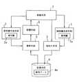
図32は従来のソフトウェアの保護を図った情報処理装置のブロック図である。図32に示した情報処理装置は、中央処理装置210、記憶装置240、入力装置220、出力装置230、及び鍵入力装置250を備えている。さらに、中央処理装置210は、内部に演算部212、制御部211、暗号化・復号部213、及び鍵格納部214を備えている。
【0006】
中央処理装置210は、情報処理装置の中心部分として機能し、データの演算や他の装置の制御等を行う。記憶装置240は、データが格納される装置であり、中央処理装置210からの制御によって中央処理装置210内の暗号化・復号部213とデータの授受を行う。
【0007】
入力装置220は、中央処理装置210からの制御で情報処理装置の外部からのデータを受け取る。出力装置230は、中央処理装置210からの制御で情報処理装置のデータを外部に出力する。鍵入力装置250は、中央処理装置210の暗号化や復号を行うのに必要な鍵をセットする。記憶装置240は、データが格納される装置であり、中央処理装置210からの制御によって中央処理装置210内の暗号化・復号部213とデータの授受を行う。
【0008】
中央処理装置210内の演算部212は入力装置220や記憶装置240から与えられたデータに対して算術演算や論理演算を行う。制御部211は記憶装置240からの命令を解釈し情報処理装置全体の制御を行う。鍵格納部214は、鍵入力装置250がセットした鍵を格納する。暗号化・復号部213は記憶装置240と演算部212との間にあり、暗号化されている記憶装置240上の命令及びデータを、鍵格納部214内の鍵を用いて演算部212が解釈できるように復号するとともに、演算部212で演算された結果を記憶装置240に書き込む際に、鍵格納部214内の鍵を用いて暗号化し記憶装置240に格納する。
【0009】
このような構成により、記憶装置240に格納されるデータを常に暗号化しておくことができる。そのため、記憶装置240内のデータを盗用してもその内容を解釈することは困難となり、データの秘匿性を高めることができる。
【0010】
ところで、この様なソフトウェアの保護機能が付いた情報処理装置においては、暗号化して格納されたデータを実行時に逐次復号して実行しなければならない。そのため、復号する際のオーバーヘッドを考慮して計算量が少ない比較的簡単なアルゴリズムの暗号化方式(例えばXOR等)を用いなければならず、結果として暗号強度が低くなるという問題がある。従って、比較的簡単なアルゴリズムの暗号化方式でも暗号強度を出来るだけ高める必要がある。
【0011】
そのため、情報処理装置ごとに暗号化の方法を変えて非公開にする努力がなされている。ただし、このような方法を用いるとデータの互換性が大きく失われてしまうという新たな問題が発生する。しかも、プログラム内の命令コードの出現頻度や暗号化されたプログラムと装置の動作の対応などから、暗号化アルゴリズムや暗号鍵が類推できるので、装置単位で見ると必ずしも暗号強度が高くなったとは言えない。
【0012】
そこで、少ない計算量で高い暗号強度を得られるような、他の手法がいくつか考えられている。例えば、プロセスまたはセグメント毎に暗号鍵を設定する情報処理装置が特開平4−102920号公報「情報処理装置」に示されている。この例は、図32の例と同様にデータを暗号化しメモリ等に格納しておきそれを中央処理装置で実行する時に復号するのに加えて、プロセスまたはセグメント毎に変換(暗号復号)回路を選択する選択回路を有してる。選択回路は一般の暗号化されていないプログラムやユーザが作成したプログラムを実行する際に、中央処理装置が変換回路を介さずにプログラムを実行するように構成されている。これにより、オペレーションシステムが管理する論理単位であるプロセスまたはセグメント毎に異なる暗号鍵を使用することができ、暗号鍵の管理をオペレーションシステムで、フレキシブルに行うので暗号強度が高くなる。
【0013】
また、近年の情報処理装置とくにマイクロプロセッサでは、キャッシュ・メモリの使用が広く行われている。そこで、上記の変換回路をキャッシュ・メモリと実メモリの間に配置して、復号されたプログラムやデータをキャッシュ・メモリ内に保持することにより、キャッシュ・メモリを効率よく使用し、暗号化/復号の処理を高速に行うことができる。
【0014】
【発明が解決しようとする課題】
しかし、上記に示したプロセスまたはセグメント毎に暗号鍵を設定する情報処理装置では、選択回路の制御を論理単位であるプロセスまたはセグメント毎に行うために、選択回路の制御はプロセスまたはセグメントを管理しているオペレーション・システム(以下OSと呼ぶ)で行わなければならない。一般にOSはソフトウェアであるので、特に比較的簡単なアルゴリズムの暗号化方式を用いるこのようなシステムでは、OSの暗号切り替え制御部分を集中して解読することにより、容易に改ざん可能である。その結果、一旦装置内部で復号したデータをそのまま外部に出力するような改ざんが可能であり、OSの一部を改ざんしただけで、すべてのプログラムやデータが解読されてしまうという問題点がある。つまり、ソフトウェアによる暗号化/復号手段の制御は装置におけるセキュリティ上の弱点になる。
【0015】
また、OSで選択回路を制御し、かつ処理の高速化を図るために、復号されたデータをキャッシュ・メモリ内に保持しようとした場合、次のような問題点を伴う。
【0016】
キャッシュ・メモリ制御方法には大きく分けて、キャッシュ・メモリ内のデータを書き換えるタイミングと実メモリのデータを書き換えるタイミングが一致しているライト・スルー方式と、タイミングが一致していないライト・バック方式がある。一般に高性能なのはライト・バック方式であるため、情報処理装置の性能を落とさずに暗号化/復号を行うには、ライト・バック方式のキャッシュ・メモリ制御方式が望ましい。
【0017】
ところが、ライト・バック方式のキャッシュを使用した場合、キャッシュ・メモリ内のデータを書き換えるタイミングと実メモリのデータを書き換えるタイミングが一致していない。そのため、ソフトウェアではキャッシュ・メモリ内に対するデータの書き込みのタイミングしか制御できない。その結果、ソフトウェアによる選択回路の制御は不可能となってしまう。つまり、OSによって選択回路を制御すると、復号されたデータをライト・バック方式のキャッシュに保持させることができない。従って、処理機能を低下させずに暗号強度を高くするには、キャッシュ・メモリ方式や仮想記憶方式のような、様々なメモリの管理方法に対応した暗号/復号鍵の管理方法が必要である。
【0018】
さらに、従来の技術は、あらかじめ決まった暗号化方式または暗号鍵で暗号化されたプログラムやデータをソフトウェアの保護機能付き情報処理装置内であらかじめ決まった復号方式または復号鍵で復号して利用し、かつ復号する際のオーバーヘッドを考慮して計算量が少ない比較的簡単な暗号化方式を用いなければならない。そのため、暗号化/復号方式または暗号/復号鍵は非公開または装置固有のものとなる。従って、装置の暗号化/復号方式または暗号/復号鍵を知りえない第三者が、装置のセキュリティ機能に守られるソフトウェアを自由に開発できないという問題点がある。
【0019】
本発明はこのような点に鑑みてなされたものであり、システムのメモリの管理方法に依存せずに高い暗号強度を得ることができるソフトウェアの保護機能付き情報処理装置及びソフトウェアの保護機能付き情報処理方法を提供することを目的とする。
【0020】
【課題を解決するための手段】
本発明では上記課題を解決するために、命令およびデータの暗号化と復号とを行いながら動作するソフトウェアの保護機能付き情報処理装置において、命令とデータを含む暗号化対象データまたはデータのみの暗号化対象データが入力されると、入力された暗号化対象データの第1の所定位置からビットを抜き出してビット情報を構成し、ビット情報に応じて暗号鍵を生成する暗号鍵生成手段と、前記暗号鍵生成手段が生成した暗号鍵を用いて、入力された暗号化対象データのうち抜き出されたビット以外の部分を暗号化し、暗号化された暗号データの第2の所定位置にビット情報を構成するビットを埋め込む暗号化手段と、前記暗号化手段で暗号化され、ビット情報を構成するビットが埋め込まれたビット情報付き暗号データを格納する記憶手段と、前記記憶手段に記憶されているビット情報付き暗号データが入力されると、入力されたビット情報付き暗号データの第2の所定位置からビットを抜き出してビット情報を構成し、ビット情報に応じて復号鍵を生成する復号鍵生成手段と、前記復号鍵生成手段が生成した復号鍵を用いて、所定の位置のビットが抜き出された暗号データを復号し、復号されたデータの第1の所定位置にビット情報を構成するビットを埋め込み暗号化対象データを生成する復号手段と、前記復号手段が生成した暗号化対象データに含まれる命令に従って、前記復号手段が生成した暗号化対象データに含まれるデータを処理する処理手段と、前記処理手段の処理終了後のデータを暗号化対象データとして前記暗号鍵生成手段へ出力する制御手段と、を有することを特徴とするソフトウェアの保護機能付き情報処理装置が提供される。
【0021】
このような構成によれば、命令とデータを含む暗号化対象データまたはデータのみの暗号化対象データが入力されると、暗号鍵生成手段により、入力された暗号化対象データの第1の所定位置からビットが抜き出されビット情報が構成され、ビット情報に応じて暗号鍵が生成される。すると、暗号化手段により、暗号鍵生成手段が生成した暗号鍵を用いて、入力された暗号化対象データのうち抜き出されたビット以外の部分が暗号化され、暗号化された暗号データの第2の所定位置にビット情報を構成するビットが埋め込まれる。そして、記憶手段により、暗号化手段で暗号化され、ビット情報を構成するビットが埋め込まれたビット情報付き暗号データが格納される。その後、記憶手段に記憶されているビット情報付き暗号データが入力されると、復号鍵生成手段により、入力されたビット情報付き暗号データの第2の所定位置からビットが抜き出され、ビット情報が構成され、ビット情報に応じて復号鍵が生成される。次に、復号手段により、復号鍵生成手段が生成した復号鍵を用いて、所定の位置のビットが抜き出された暗号データが復号され、復号されたデータの第1の所定位置にビット情報を構成するビットが埋め込まれ、暗号化対象データが生成される。さらに、処理手段により、復号手段が生成した暗号化対象データに含まれる命令に従って、復号手段が生成した暗号化対象データに含まれるデータが処理される。そして、制御手段により、処理手段の処理終了後のデータが、暗号化対象データとして暗号鍵生成手段へ出力される。
【0026】
【発明の実施の形態】
以下、本発明の実施の形態を図面に基づいて説明する。
図1は本実施の形態の関連技術を示す図である。本発明のソフトウェアの保護機能付き情報処理装置は、暗号化対象データ(命令とデータとを含む)の属性に応じて暗号鍵1aを生成する暗号鍵生成手段1と、暗号データの属性に応じて復号鍵2aを生成する復号鍵生成手段2と、暗号鍵生成手段1が生成した暗号鍵1aを用いて、暗号化対象データを暗号化する暗号化手段3と、暗号化手段3が暗号化した暗号データ4aを格納する記憶手段4と、記憶手段4に記憶されている暗号データ4aを、復号鍵生成手段2が生成した復号鍵2aを用いて復号する復号手段5と、復号手段5が復号したデータに含まれる命令に従って、復号したデータを処理する処理手段6と、処理手段6の処理終了後のデータを、暗号化対象データとして暗号化手段3へ出力する制御手段7と、で構成されている。
【0027】
このような構成によれば、暗号化対象データが入力されると、暗号鍵生成手段1が、その暗号化対象データの属性に応じて暗号鍵1aを生成する。この暗号鍵1aを用いて、暗号化手段3が暗号化対象データを暗号化し、暗号データ4aが記憶手段4に格納される。そして、制御手段7より、暗号データ4aの処理要求があると、復号鍵生成手段2が暗号データ4aの属性に応じて復号鍵2aを生成する。復号手段5は、その復号鍵2aを用いて、暗号データ4aを復号する。復号されたデータは、処理手段6により処理される。制御手段7は、処理手段6により処理されたデータを暗号化対象データとして暗号化手段3に対して出力する。
【0028】
これにより、暗号鍵と復号鍵とが暗号化対象データと暗号データとの属性によって定まるため、属性の異なるデータは異なる鍵で暗号化/復号され、暗号強度の高い暗号データを得ることができる。なお、上記の説明における属性とは、データのアドレス、アドレス領域、仮想アドレス、あるいはセグメントなどの、対象となるデータと何等かの関連性を有する各種情報を指す。
【0029】
以下に本発明のソフトウェアの保護機能付き情報処理装置の具体的な構成について説明する。図2はソフトウェアの保護機能付き情報処理装置のハードウェア構成例を示すブロック図である。この情報処理装置は、まずメインの構成として、データの演算やメモリアクセス等の制御を行うMPU(Micro Processing Unit )である情報処理手段11、情報処理手段11が出力したデータを暗号化する暗号化手段12、情報処理手段11へ入力すべき暗号データを復号する復号手段13、暗号化/復号の際の暗号鍵と復号鍵とを選択する鍵選択手段14、及び鍵選択手段14が選択した鍵を暗号化手段12と復号手段13とに供給する鍵供給手段15が設けられている。これらの要素は、安全保護容器10に収められている。また、暗号化手段12と復号手段13とは、システムバス20を介してRAM(Random Access Memory)である記憶手段21と、I/Oインタフェース(I/O)22に接続されている。
【0030】
I/O22は、システムバス20とペリフェラルバス23との間のデータ伝送を制御する。ペリフェラルバス23には、イーサネットを介したデータ通信を行うイーサネット・コントローラ24、CD−ROMのデータを読み取るCD−ROMドライブ25、及び大容量のデータの磁気的なリード/ライトをするハードディスク26が接続されている。
【0031】
以上の構成において、まず、予め決められた暗号化方式と暗号鍵で暗号化されたデータがネットワークやハードディスク26から供給される。暗号化されたデータを情報処理手段11で実行するためには、そのデータを記憶手段21にロードする必要がある。この時、暗号化されたデータの復号に使用する鍵の情報を、鍵選択手段14に送っておく。鍵選択手段14は鍵供給手段15に指示して復号手段13に復号鍵を渡すとともに、データの格納先アドレスに対応した暗号鍵を選択し、鍵供給手段15に指示して暗号化手段12に渡す。すなわち、暗号化されたプログラムまたはデータは復号手段13で一旦復号され、さらに暗号化手段12において格納先アドレスに対応した暗号鍵で暗号化され、記憶手段21にロードされる。プログラム実行時は、鍵選択手段14が鍵供給手段15にデータの格納先アドレスに対応した復号鍵を選択指示して復号手段13に渡すことで復号が行われる。
【0032】
また、この情報処理装置の情報処理手段11、暗号化手段12、復号手段13、鍵選択手段14、及び鍵供給手段15は保護容器10内に格納されている。保護容器10は、内部の装置が外部からのプロービングに対して保護されるような仕組みを備えている。保護容器10はそれが取り外されたり穴を開けられたりした時に内部の装置の動作を停止させたり秘匿データが読み出されないように消去する機能を有しており、これにより暗号化/復号方式や暗号/復号鍵および復号されたデータの盗用や改ざんを完全に防ぐことができる。したがって、復号されたデータが存在する部分はすべて保護容器内に格納しなければならない。保護容器は攻撃対抗容器(Tamper Resistant Module )とも呼ばれ、その例としては、米国特許4,593,384号や特開昭63ー124153号公報、特開平2−44447号公報などがある。
【0033】
このような安全保護容器は、複雑な経路をたどる導体路や論理素子が表面に形成された包囲体で秘密情報を取り扱う回路を囲み、内部の秘密情報を不正に解析しようとして包囲体を破壊した場合に導体路の切断や短絡または論理素子の動作不良が生じ、それをトリガーとして暗号鍵などの秘密情報を消去するという構造になっている。したがって暗号鍵、復号鍵及び暗号化されていないデータ等を取り扱うMPU、暗号化装置及び復号装置を安全保護容器内に格納すれば、不正を行おうとする者は暗号を解読する手掛かりをほとんど失うことになる。暗号鍵、復号鍵及び暗号化されていないデータ等を取り扱うこれらの装置は1つのLSIに集積して実現するのが望ましいが、複数のLSIで構成した場合にはMCM(マルチ・チップ・モジュール)パッケージなどに封止して、外部にチップ間の配線が露出しないようにしてもよい。また、秘密情報の保持にはバッテリーバックアップされたSRAM(Static RAM)を用いて、容器が開けられると同時に電力の供給が断たれ、SRAMの内容が失われるような構造にしてもよい。
【0034】
以上の例は、ネットワーク等を経由して入力された暗号データも、内部の暗号データと同じアルゴリズムで復号する場合の例である。ところが、この方式では、外部からこの情報処理装置に提供するソフトウェアも、内部の暗号データと同様に計算量の少ないアルゴリズムで暗号化しなければならない。そこで、複雑なアルゴリズムの復号を行う復号手段を別に設けることによって、この情報処理装置に提供するソフトウェアの暗号強度の強化を図ることができる。以下に、その例を示す。
【0035】
図3は複数の復号手段を有するソフトウェアの保護機能付き情報処理装置のハードウェア構成を示すブロック図である。この情報処理装置には、MPUである情報処理手段31と、流通ソフト復号手段32と、暗号化手段33と、復号手段34と、RAMである記憶手段41が設けられている。さらに、I/Oインタフェース(I/O)42を介してハードディスク46と、CD−ROMドライブ45と、イーサネット・コントローラ44とが接続されている。また、情報処理手段31、流通ソフト復号手段32、暗号化手段33、及び復号手段34は、安全保護容器30に収められている。安全保護容器30内の各構成要素と、記憶装置41と、I/O42とはシステムバス40で接続されている。I/O42と、イーサネット・コントローラ44と、ハードディスク46と、CD−ROMドライブ45とは、ペリフェラルバス43で接続されている。
【0036】
以上の構成において、データはまず、暗号化され、ネットワークやCD−ROM等によってソフトウェア提供者からユーザに提供される。この時用いられる暗号化方式は汎用的で暗号強度の高いものを用いる。例えば、ソフトウェア提供者は暗号化方式としてDES(Data Encryption Standard: 米商務省標準局〔現在の米国標準技術協会〕が1977年に公表した暗号アルゴリズム)等を用いて、ユーザに提供するデータを暗号化する。そして復号鍵は例えばRSA(Rivest,Shamir,Adleman :Ronald Rivest,Adi Shamir,leonard Adlemanの3氏が考案したアルゴリズム)暗号によってソフトウェアの保護機能付き情報処理装置の公開鍵で暗号化し、暗号化されたデータとペアにしてユーザに提供する。ユーザは暗号化されたデータと装置の公開鍵で暗号化された復号鍵をI/O42から流通ソフト復号手段32に送って復号する。復号されたデータは直接暗号化手段33に送られ非公開の暗号方法または暗号鍵で暗号化される。そのため、ユーザは復号されたデータにアクセスすることはできない。暗号化手段33で暗号化されたデータは記憶手段41に格納される。情報処理手段31は、記憶手段41に格納されている暗号化されたデータを復号手段34で復号して受けとり、そのデータに含まれる命令を実行する。情報処理手段31が出力するデータの中で暗号化が必要なものは暗号化手段33で暗号化して記憶手段41に格納する。
【0037】
このように公開された暗号化方式と暗号鍵を用いて暗号化されたデータをソフトウェアの保護機能付き情報処理装置内に取り込んで流通ソフト復号手段32で復号できるので、ソフトウェア提供者は暗号化手段33及び復号手段34で使用する暗号化/復号方式または暗号/復号鍵を知る必要はなく、ただ情報処理手段31用にソフトウェアを開発すればよい。つまり、ソフトウェアの保護機能付き情報処理装置内の暗号化/復号方式または暗号/復号鍵を知りえない第三者が、ソフトウェアの保護機能付き情報処理装置に守られるソフトウェアを自由に開発できる。
【0038】
また、この情報処理装置も図2に示した例と同様に安全保護容器30で重要な構成要素が保護されているため、内部の装置が外部からのプロービングに対して保護されている。
【0039】
ここで、図2に示した情報処理装置と図3に示した情報処理装置とを融合させることにより、さらにデータの保護を強化することができる。この例を図4に示す。
【0040】
図4の情報処理装置は、情報処理手段51、流通ソフト復号手段52、暗号化手段53、復号手段54、鍵供給手段56、鍵選択手段55、記憶手段61、I/O62、ハードディスク66、CD−ROMドライブ65、イーサネット・コントローラ64、保護容器50、システムバス60、ペリフェラルバス63からなる。なお、この情報処理装置は、仮想記憶方式を採用しており、ページ単位でデータを取り扱うものとする。
【0041】
このような構成において、暗号化されたデータと復号鍵は、ネットワークやCD−ROM等によってソフトウェア提供者からユーザに提供される。この暗号化されたデータを実行するためにロードするには、まず装置の公開鍵で暗号化された復号鍵をI/O62を介して流通ソフト復号手段52に送って復号する。次に、復号されたデータは直接暗号化手段53に送られる。同時に鍵選択手段55は、データの格納先ページ番号に対応した暗号鍵群を選択する。選択された暗号鍵群は、鍵供給手段56により暗号化手段53に供給される。そして、暗号化手段53に送られたデータは、鍵供給手段56から供給された鍵群によって暗号化される。このときの暗号化方法または暗号鍵は非公開であるので、ユーザは復号されたデータにアクセスすることはできない。そして暗号化手段53でページ毎に異なる暗号鍵で暗号化されたデータは、記憶手段61に格納される。また記憶手段61に格納しきれないページはハードディスク66にスワップアウトされる。情報処理手段51が記憶手段61に格納されている暗号化されたプログラムを実行するには、鍵選択手段55がデータの格納先ページに対応した復号鍵群を鍵供給手段56から選択し、選択された復号鍵群で復号手段54がデータを復号して、復号されたプログラムを情報処理手段51が実行する。情報処理手段51が出力するデータの中で暗号化が必要なものは暗号化手段53で暗号化して記憶手段61に格納する。
【0042】
図5は鍵選択手段で鍵群を選択する例の詳細を示す図である。鍵選択手段55はページ内のデータに対応する鍵を特定する鍵特定手段55aを有する。鍵供給手段56には、複数の鍵群(A群561、B群562、C群563)が格納されている。鍵群の内の各鍵は、ページオフセットと対応している。そして、情報処理手段51から暗号化/復号すべきページのページ番号が出力されると、鍵選択手段55がページ番号に応じて鍵群を指定する。この際、鍵特定手段551が、ページ内の各ブロックに対応する鍵群内の鍵を特定する。この例では、鍵選択手段55はC群563を指定している。鍵供給手段56は、指定されたC群563の鍵群を、暗号化手段53と復号手段54とに供給する。暗号化手段53と復号手段54とは、暗号化あるいは復号すべきページの各ブロックを供給された鍵群の個々の鍵で暗号化あるいは復号する。
【0043】
ここでページの大きさを256バイト、1つの鍵で暗号化する暗号ブロックを16バイトとすると、鍵群はそれぞれ16個までの鍵で構成される。いま1バイト毎にページ内のオフセットアドレスが与えられ、鍵群が16個の鍵からなるとすると、鍵特定手段はオフセットアドレスの任意の4ビットでどの鍵を使用するか特定する。また、暗号ブロック内の任意の4ビット(プログラムまたはデータそのものの任意の4ビットで、この4ビットは暗号化されない)でどの暗号/復号鍵を使用するか特定してもよい。
【0044】
以上のようにして、ソフトウェアの保護機能付き情報処理装置内の暗号化/復号方式または暗号/復号鍵を知りえない第三者が、ソフトウェアの保護機能付き情報処理装置に守られるソフトウェアを自由に開発でき、暗号強度を高くすることができる。
【0045】
ここで、所定タイミングで暗号データの鍵を変更することにより、さらに暗号強度を高くすることができる。以下にその例を示す。
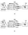
図6は再暗号化手段による鍵の変更方法の第1の例を示す図である。この例では暗号化と復号に同一の鍵を用いることとする。(A)は鍵の変更前の状態を示している。この例では、鍵供給手段56a内には「A」、「B」、「C」の3つの鍵56aa,56ab,56acが設けられている。そして、鍵選択手段55aは暗号鍵、復号鍵共に、「C」の鍵56acを選択している。従って、暗号化手段53aと復号手段54aとには、鍵「C」が供給されている。この状態で、鍵選択手段55aに対して、再暗号化手段57から鍵の変更指令が出力される。ここでは、ある期間ごとに鍵の変更指令を出力するものとする。なお、再暗号化手段57は、実際には、メインメモリにロードしたプログラムを情報処理手段が実行することにより実施される機能である。また、情報処理手段がプログラムに従ってDMAC(Direct Memory Access Controller) に命令して実行させてもよい。
【0046】
(B)は鍵の変更指令出力後の状態を示す図である。ある期間が過ぎて鍵の変更指令が出力されると、再暗号化手段57の制御に従って、鍵選択手段55aは選択する暗号鍵を「C」から「A」に変更する。これにより、鍵「A」が、鍵供給手段56aから暗号化手段53aに渡される。この状態で記憶装置内の鍵「C」で暗号化されているデータを復号して、さらに鍵「A」で暗号化して記憶装置内に戻す。これにより、暗号鍵を鍵「C」から鍵「A」に変更しデータを再暗号化できる。
【0047】
(C)は再暗号化が必要な全てのデータの再暗号化が終了した後の状態を示す図である。再暗号化手段57は、鍵「C」で暗号化されているデータの全てを鍵「A」で暗号化し終わった時点で、復号鍵を鍵「A」にするように鍵選択手段55aに指令する。鍵選択手段55aが、指示に従って復号鍵を変更した結果、鍵供給手段56aから復号手段54aに鍵「A」が渡される。
【0048】
このように再暗号化手段57によって鍵選択手段55は鍵をダイナミックに変更することができるので、暗号強度を高くすることができる。また、一度に用いる暗号/復号鍵または暗号/復号鍵群は、鍵供給手段56から供給される鍵または鍵群の1つに限る必要はなく、複数の鍵または複数の鍵群を一度に使用してもよい。 図7は再暗号化手段による鍵の変更方法の第2の例を示す図である。この例でも暗号化と復号に同一の鍵を用いるものとする。(A)は鍵の変更前の状態を示している。鍵供給手段56bは「A」,「B」,「C」の3つの鍵56ba,56bb,56bcが供給可能である。鍵選択手段55bは、アドレス55ba、暗号鍵55bb、及び復号鍵55bcの項目が設けられた鍵管理テーブルを有している。この対応表によって、アドレスと鍵との対応関係を管理している。この例では、アドレス「0」には、暗号鍵「A」,復号鍵「A」が対応しており、アドレス「1」には、暗号鍵「B」,復号鍵「B」が対応しており、アドレス「2」には、暗号鍵「C」,復号鍵「C」が対応している。そして、再暗号化手段57aは、鍵選択手段55bに対して、アドレス「2」のデータの鍵変更指令を出力するものとする。
(B)は鍵の変更指令出力後の状態を示す図である。一定時間が過ぎてアドレス「2」の鍵を「C」から「A」に変更する場合、再暗号化手段57aは鍵選択手段55b内の鍵管理テーブルのアドレス「2」の暗号鍵を「A」に変更する。従って、鍵選択手段55bは鍵供給手段56bに指示して暗号鍵「A」を暗号化手段に渡し、復号手段には引き続き復号鍵「C」を渡す。この状態で記憶装置内の復号鍵「C」で暗号化されているアドレス「2」のデータを復号して、さらに暗号鍵「A」で暗号化して記憶装置内に戻す。これにより、暗号鍵を「C」から「A」に変更し、アドレス2のデータを再暗号化できる。
【0049】
(C)は再暗号化が必要な全てのデータの再暗号化が終了した後の状態を示す図である。再暗号化手段57aは、再暗号化が終わった時点で、鍵選択手段55b内の鍵管理テーブルのアドレス「2」の復号鍵を「C」から「A」に変更する。この例でも、アドレスをアドレス領域に、鍵を鍵群にすることもできる。
【0050】
上記の例では、鍵供給手段内には複数の鍵が予め登録されているが、この登録されている鍵を変更することもできる。以下にその例を示す。
図8は鍵供給手段内の鍵を変更する場合の例を示す図である。この例では暗号化と復号に同一の鍵を用いることとする。鍵供給手段内の鍵を変更するには、図6に示したような再暗号化の手順が必要になる。
【0051】
(A)は鍵の変更前の状態を示している。この例では、鍵供給手段56c内には「A」、「B」、「C」の3つの鍵56ca,56cb,56ccが設けられている。そして、鍵選択手段55cは暗号鍵、復号鍵共に、「C」の鍵56ccを選択している。従って、暗号化手段53cと復号手段54cとには、鍵「C」が供給されている。この状態で、鍵選択手段55cに対して、再暗号化手段57bから鍵の変更指令が出力される。ここでは、ある期間ごとに鍵の変更指令を出力するものとする。
【0052】
(B)は鍵の変更指令出力後の状態を示す図である。ある期間が過ぎて鍵の変更指令が出力されると、再暗号化手段57bの制御に従って、鍵選択手段55cは選択する暗号鍵を「C」から「A」に変更する。鍵「A」が、鍵供給手段56cから暗号化手段53cに渡される。この状態で記憶装置内の鍵「C」で暗号化されているデータを復号して、さらに鍵「A」で暗号化して記憶装置内に戻す。
【0053】
(C)は再暗号化が必要な全てのデータの再暗号化が終了した後の状態を示す図である。再暗号化手段57bは、鍵「C」で暗号化されているデータの全てを鍵「A」で暗号化し終わった時点で、復号鍵を鍵「A」にするように鍵選択手段55cに指令する。鍵選択手段55cが、指示に従って復号鍵を変更した結果、鍵供給手段56cから復号手段54cに鍵「A」が渡される。そして、「C」の鍵56ccを、「D」の鍵56cdに変更する。このようにして、鍵供給手段56c内の鍵「C」が廃棄され鍵「D」の供給が開始される。
【0054】
ここで鍵Dの生成手段としては、新たに鍵を作成する方法と多数の鍵が登録された鍵のテーブルから選択する方法とがある。図9は、鍵の生成方式を示す図である。ここで、以下に示す2つの例は、鍵供給手段56cに関しては、図8に示したものと変わるところがないため、同じ符号を付して説明を省略する。
【0055】
(A)は新たな鍵を作成する方式を示す図である。鍵生成手段58aは、内部に原型となる鍵58aaを有しており、この鍵58aaを変形させ新たな「D」の鍵56abを生成する。鍵生成手段58aとしては、シリアル・シフト・レジスタを用いた疑似乱数発生装置や、装置固有の係数と時刻を変数とした関数を用いることができる。(B)は鍵テーブルを利用する方式を示す図である。鍵生成手段58b内には、多数の鍵58ba〜58beが登録されている。そして、この中の任意の鍵58bdを選択し、「D」の鍵とする。
【0056】
このように2通りの方法が考えられるが、もちろん鍵生成手段と鍵テーブルを組み合せてもよい。また、鍵選択手段からの鍵の指定を、名前ではなく識別子で行うことにより、鍵供給手段内の鍵が変更されたことを鍵選択手段が認識する必要がなくなる。
【0057】
図10は識別子を用いた鍵の選択方式を示す図である。(A)は鍵の変更前の状態を示す図である。鍵供給手段56dは「A」、「B」、「C」の3つの鍵56da,56db,56dcが登録されており、各鍵56da,56db,56dcには、0〜2の識別子が付けられている。鍵選択手段55dは、暗号鍵識別子を「2」、復号鍵識別子を「2」として出力している。従って、暗号化手段53dと復号手段54dとには、鍵「C」が供給されている。この状態で、鍵「C」が鍵「D」に変更される。
【0058】
(B)は鍵の変更後の状態を示す図である。鍵選択手段55dは、同じように暗号鍵識別子を「2」、復号鍵識別子を「2」として出力しているが、鍵供給手段56d内の「2」の識別子には、鍵「D」が登録されている。従って、暗号化手段53dと復号手段54dとには、鍵「D」が供給されている。このようにして、鍵選択手段55dは、鍵Cが鍵Dに置き換わってしまった事を認識する必要がなくなる。
【0059】
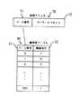
次に、鍵を書き換えるタイミングを時間管理手段で管理し、再暗号化手段で異なる鍵でデータを再暗号化して鍵を更新する例を示す。時間管理手段は、時間管理テーブルを用いて、再暗号化のタイミンングを管理することができる。図11は時間管理テーブルを示す図である。時間管理テーブル59は、鍵識別子59a、鍵寿命59b、経過時間59c、書き換えフラグ59dの項目を有している。そして、鍵識別子59aの「0〜2」は、それぞれ鍵「A」〜「C」と対応している。鍵寿命59bには、その鍵を書き換える周期が設定されている。経過時間59cは、現在の鍵の使用開始からの経過時間を示している。書き換えフラグ59dは、値が「0」で、経過時間が鍵寿命を超えていないことを示し、値が「1」で、経過時間が鍵寿命を超えたことを示す。
【0060】
この時間管理テーブル59を用いて、時間管理手段はそれぞれの鍵の寿命と、鍵を書き換えてからの経過時間を管理する。ここで経過時間が鍵寿命を超えた鍵の有効鍵通知手段である書き換えフラグを立てて、鍵の書き換えおよび使用している鍵の変更が必要な事を再暗号化手段に知らせる。
【0061】
図では、識別子「0」の寿命は「10分」、経過時間は「1分」、書き換えフラグは「0」である。識別子「1」の寿命は「60分」、経過時間は「30分」、書き換えフラグは「0」である。識別子「2」の寿命は「60分」、経過時間は「61分」、書き換えフラグは「1」である。つまり、識別子「2」は、経過時間が寿命を超えている。
【0062】
図12は時間管理手段の処理手順を示すフローチャートである。
〔S1〕寿命となった鍵識別子があるか否かを判断し、寿命となった鍵識別子があればステップS2に進み、無ければこのステップを繰り返す。
〔S2〕寿命となった鍵識別子の書き換えフラグを立てる。
〔S3〕フラグが立っている鍵識別子の鍵が使用されているか否かを判断し、使用されていればこのステップを繰り返し、使用されていなければステップS4に進む。なお、フラグが立っている鍵識別子の鍵が使用されているか否かの情報は、再暗号化手段から与えられる。
〔S4〕寿命となった鍵識別子の鍵の書き換えを行い、ステップS1に進む。
【0063】
図13は再暗号化手段の処理手順を示すフローチャートである。
〔S5〕書き換えフラグを読む。
〔S6〕書き換えフラグが立っているか否かを判断し、書き換えフラグが立っていればステップS7に進み、書き換えフラグが立っていなければステップS5へ進む。
〔S7〕フラグが立っている鍵識別子の鍵で暗号化されているデータを、フラグが立っていない鍵識別子の鍵で暗号化し直す。
〔S8〕フラグが立っている鍵識別子を使用していないことを、時間管理手段に知らせ、ステップS5に進む。
【0064】
図12、図13に示したように時間管理手段と再暗号化手段が動作することにより、まず、寿命となった鍵があったなら、時間管理手段がその鍵の鍵アドレスに書き換えフラグを立てる。すると、再暗号化手段は、書き換えフラグが立っていることを検出し、フラグが立っている鍵識別子の鍵をフラグが立っていない鍵識別子の鍵に鍵変更をして、時間管理手段に知らせる。時間管理手段はフラグが立っている鍵アドレスの鍵が使用されていない事を確認して、寿命となった鍵アドレスの鍵を書き換えることを鍵供給手段に要求する。このようにして安全に鍵の書き換えを行うことができる。
【0065】
図14は、時間管理手段の鍵書き換えに関する他の動作例を示すフローチャートである。この例では、書き換えフラグを立てて10分の間に必ず鍵の書き換えを行う。
〔S11〕寿命となった鍵識別子があるか否かを判断し、寿命となった鍵識別子があればステップS12へ進み、なければこのステップを繰り返す。
〔S12〕寿命となった鍵識別子の書き換えフラグを立てる。
〔S13〕フラグが立っている鍵識別子の鍵が使用されているか否かを判断し、使用されていればステップS14に進み、使用されていなければステップS15に進む。
〔S14〕フラグが立てられてから10分が経過したか否かを判断し、経過していればステップS15に進み、経過していなければステップS13に進む。
〔S15〕寿命となった鍵識別子の鍵の書き換えを要求し、ステップS11に進む。
【0066】
このようにすることで、再暗号化手段が改ざんされて、鍵の変更を行わなくなってしまった場合でも、鍵は強制的に書き換えられ、その結果情報処理手段が正常動作しなくなることで、自己破壊的にデータの秘匿性を保つことができる。この例では10分の間に必ず鍵の書き換えを行うようにしたが、実際は、システムの使用状況や情報処理手段1の処理能力を勘案して決定するとよい。また、鍵を強制的に書き換える代わりにNMI(Non Maskable Interrupt)を発生させて、システムをリセットしてもよい。
【0067】
次に、図4の例に示す鍵選択手段55の鍵管理方式の幾つかの例を説明する。どのデータをどの暗号化方式及びどの鍵で暗号化したかを管理する方法としては、記憶手段61のアドレスを用いるのが簡単である。特に仮想記憶方式を使わないシステムでは、記憶手段61のアドレスを直接用いるか、あるいは何等かの単位毎に管理すればよい。例えばアドレスと暗号鍵の対応を管理する鍵管理テーブルを用いるとよい。
【0068】
仮想記憶方式で記憶を管理するシステムでは、記憶手段61に格納しきれないページまたはセグメントは記憶手段61からハードディスク66に移される。ハードディスク66に移されたページまたはセグメントは記憶手段61の同じアドレスに戻されるとは限らないので、記憶手段61のアドレスを直接用いて鍵の管理を行うことはできない。そこで仮想アドレスによる鍵の管理が必要になる。仮想アドレスによる鍵の管理の方法としては、仮想アドレスを直接用いる方法と、ハードディスク66と記憶装置61の間でやり取りされる物理単位で固定長のページを用いる方法と、ハードディスク66と記憶装置61の間でやり取りされる論理単位で可変長のセグメントを用いる方法と、仮想記憶空間を複数持つような多重仮想記憶方式をとる場合は仮想記憶空間毎に鍵を管理する方法がある。
【0069】
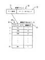
ページによって仮想記憶を管理する場合、一般に仮想アドレスはページ番号とページオフセットから成っているので、例えばページ番号と鍵識別子の対応を管理する鍵管理テーブルを用いるとよい。図15はページ番号と鍵識別子の対応を管理する鍵管理テーブルの例を示す図である。通常、仮想アドレス70はページ番号71とページ・オフセット72で構成されている。そこで、鍵管理テーブル80には、ページ番号81に対応して鍵識別子82を登録しておく。従って、ある仮想アドレスへのアクセスが発生すると、その仮想アドレスのページ番号を抽出する。そして、鍵管理テーブル80から、抽出したページ番号に対応する鍵識別子を選択することができる。
【0070】
また、鍵管理テーブルが大きくなる場合には、鍵管理テーブルを記憶装置61に置き、頻繁に使用する鍵管理テーブルの一部を鍵選択手段内のTLB(Table Lookaside Buffer)に保持して使用し、TLBにないものは記憶装置61から取り出して、TLBを更新するようにしてもよい。図16は鍵選択手段内のTLBを示す図である。鍵選択手段内のTLB90は、アドレス・タグ91と鍵識別子92との格納部で構成されている。アドレス・タグ91には、仮想アドレス70のページ番号71が格納され、格納されたページ番号71に対応する鍵識別子が鍵識別子92の格納部に格納される。これにより、鍵管理テーブルを保持するためのメモリサイズを縮小することができる。
【0071】
しかし、一般にページによって仮想記憶を管理するシステムの場合、仮想記憶を管理するためのページテーブルを持ち、仮想アドレスから物理アドレスへの変換と、各ページが主記憶内に存在するか否かを管理し、またそのためのハードウエアであるMMU(Memory Management Unit)を有している。そこで、鍵識別子の情報をページテーブルに追加することで、MMUと鍵管理テーブルの機能を融合させることができる。図17はMMU内のTLBを示す図である。MMU内のTLB100には、アドレス・タグ101、主記憶内に存在するか否かを示すビット102、鍵識別子103、及びページ・アドレス104の格納部で構成されている。アドレス・タグ101には仮想アドレス70のページ番号71が格納されており、主記憶内に存在するか否かを示すビット102により、そのページがメモリ内にあるか否かが示されている。そして、鍵識別子103により、そのページの鍵が示されており、ページ・アドレス104により、そのページのアドレスが示されている。また、セグメントによって管理する場合もページと同様に鍵の管理ができる。
【0072】
仮想記憶とライトバック方式のキャッシュ・メモリを使用して、アドレスによる暗号鍵管理を行った場合ソフトウェアによる鍵の選択は不可能である。そこで、図17のようにMMUを利用することで、ハードウェアによる鍵の選択が可能になる。つまり、MMU内ではページ番号およびセグメント番号に対応したアドレスタグをアドレスとした連想記憶方式でページテーブルおよびセグメントテーブルの一部を保持しており、通常キャッシュ・メモリ内に存在するデータが属するページまたはセグメントは、MMU内に存在する。ページテーブルまたはセグメントテーブルがMMU内に存在するので、MMUから鍵アドレスを取得することで、ハードウェアによる鍵の選択が可能になる。
【0073】
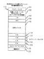
図18はインテル社製のMPUであるi80286のタスク状態セグメントに鍵アドレスの情報を付加した例を示す図である。タスク状態セグメント110は、バック・リンク111、特権レベル0,1,2に対するスタック・ポインタSP,SSの初期値112、IP113、SR114、汎用レジスタ115、ES116、SS117、CS118、DS119、タスクLDTセレクタ120、及び鍵識別子121の格納領域がある。このタスク状態セグメント110はタスク毎に生成されるため、このようにする事で、タスク(プロセス)毎に暗号鍵を管理する事ができる。またi80286ではタスク毎に仮想記憶空間を有する多重仮想記憶方式を採用しているので、仮想記憶空間毎の鍵管理の例でもある。
【0074】
暗号化されていないデータを図4に示したような本発明の装置で実行する方法は2種類ある。1つは暗号化されていないデータも暗号化手段53で暗号化して、暗号化されて供給されたデータと同様に取り扱う方法である。2つ目は暗号化されて供給されたデータが必ず流通ソフト復号手段52で復号される場合、このことを利用して、流通ソフト復号手段52で復号されたデータのみに有効な鍵アドレスを与えるようにする方法である。このようにして、暗号化されたデータの秘匿性を保ったままで暗号化されていないデータも扱うようにすることができる。
【0075】
以上の例は、暗号化/復号の対象となるデータに関連性のあるアドレス等の情報を用いて鍵管理をするものであるが、データに関連性のある情報ではなく、データの内容による鍵管理も可能である。例えば、プログラムおよびデータの内容の一部分で暗号鍵を選んで、残りの部分を暗号化する方法が考えられる。以下に、その例を説明する。
【0076】
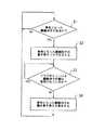
図19はデータの内容による鍵管理の暗号化の処理手順を示すフローチャートである。これは、暗号化手段が行う処理である。
[S21]暗号化されるべきデータを暗号化手段へ読み込む。
[S22]読み込んだデータから特定の数ビットを抜き出す。
[S23]ステップS22において抜き出した数ビットに対応する暗号鍵を、鍵テーブルより選択する。
[S24]ステップS23において選択した暗号鍵を用いて、暗号化されるべきデータの、抜き出した数ビット以外の部分を暗号化する。
[S25]暗号化したデータに、ステップS22において抜き出した数ビットを埋め込む。
【0077】
以上の各ステップにおいて、暗号化されるデータの状態がどのように変化するかを、図20の状態遷移図に従って説明する。
(A)は、ステップS21の状態を示す図である。暗号化すべきデータ130が読み込まれる。暗号化される前のデータ130は32ビットからなり、情報処理手段で直接処理を行うことのできる状態にある。
【0078】
(B)は、ステップS22の状態を示す図である。暗号化される前のデータ130から、ある規定に従った特定の数ビットを抜き出す。例では7、11、15及び23ビット目の4ビットのデータを抜き出している。従って、28ビットのデータ131が残ることとなる。抜き出したビットは、所定の配列に並べられビット情報132となる。
【0079】
(C)は、ステップS23の状態を示す図である。4ビットのビット情報132に対応する暗号鍵を、予め用意された鍵テーブル140から選択する。鍵テーブル140は、抜き出したビットによるビット情報140aに対応する鍵140bが一意に選択できるようになっている。例では抜き出すビット数が4ビットであることから鍵も4ビットで分類されており、16種類のビット情報「0000」,「0001」,「0010」・・・のそれぞれに対応する16個の鍵141,142,143・・・が存在する。この例では、抜き出したビットによるビット情報132の値が「0010」であるため、鍵143が暗号鍵として選択されている。
【0080】
(D)は、ステップS24の状態を示す図である。選択された鍵143を暗号鍵に用いて、抜き出した4ビットのビット情報132以外の28ビットのデータ131を暗号化し、28ビットの暗号データ133を生成する。
【0081】
(E)は、ステップS25の状態を示す図である。(B)において抜き出した4ビットのビット情報132を、28ビットの暗号データ133に埋め込み、32ビットの暗号データ134として記憶手段に格納する。
【0082】
抜き出した4ビットのビット情報132を埋め込む方法は、復号の際にビット情報132を分離するための方法とセットで決定されている。この2つの方法が一意に決定できるのであれば、埋め込む位置を最初に抜き出したビット位置と同じにする必要はない。また、最後にスクランブル等を行い、第三者に暗号鍵の選択に用いたビットの位置を容易に見つけられないようにすることも可能である。なお、最後にスクランブルを行う場合には、ステップ24で行う暗号化はスクランブル以外の方法である必要がある。更に、抜き出した4ビットのビット情報132を暗号化した28ビットの暗号データ133に埋めこむ際、XOR等の暗号化方法で暗号化して埋めこんでもよい。
【0083】
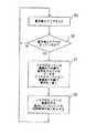
図21は、データの内容による鍵管理の復号の処理手順を示すフローチャートである。
[S31]暗号化されているデータを復号手段へ読み込む。
[S32]復号手段において、読み込んだデータから特定の数ビットを抜き出す。
[S33]ステップS32において抜き出した数ビットに対応する復号鍵を、鍵テーブルより選択する。
[S34]ステップS33において選択した復号鍵を用いて、復号されるべきデータの、抜き出した数ビット以外の部分を復号する。
[S35]復号したデータに、ステップ32において抜き出した数ビットを埋め込む。
【0084】
復号されるデータの状態がどのように変化するかを、図22の状態遷移図に従って説明する。32ビットのデータを復号する場合を考える。但しこの32ビットは、図19及び図20に示した暗号化方法に従って暗号化された後、記憶手段に格納されていたものとする。なお、この例は暗号鍵と同じ鍵を復号鍵とする場合である。
【0085】
(A)は、ステップS31の状態を示す図である。暗号データ134を記憶装置から読み込む。暗号データ134は32ビットからなり、情報処理手段で直接処理を行うことのできない状態にある。
【0086】
(B)は、ステップS32の状態を示す図である。暗号データ134から、特定の数ビットを抜き出し、ビット情報132を得る。例では6、13、27及び30ビット目の4ビットを抜き出している。この4ビットのデータを抜き出す位置は、暗号化の際に、ビット情報132の各ビットを埋め込んだ位置である。この結果、28ビットの暗号データ133が残ることとなる。
【0087】
(C)は、ステップS33の状態を示す図である。抜き出した4ビットのビット情報132に対応する鍵143を、予め用意された鍵テーブル140から選択する。暗号化の際に用いられたビット情報の値が「0010」であるため、鍵テーブル140を用いて、暗号化の際の鍵143と同一の鍵を選択することができる。この選択された鍵143が復号鍵となる。
【0088】
(D)は、ステップS34の状態を示す図である。選択した鍵143を復号鍵として、抜き出した4ビットのデータ132以外の28ビットの暗号データ133を復号し、28ビットのデータ131を生成する。
【0089】
(E)は、ステップS35の状態を示す図である。(B)において抜き出した4ビットのデータ132を、28ビットのデータ131に埋め込み、32ビットのデータ130を得る。埋め込む位置は、暗号化の際に4ビットのデータを抜き出した位置と同じ位置である。この結果、暗号化する前のデータと同一のデータ130が得られる。
【0090】
以上のような方法により、復号鍵の抽出に用いるデータが復号の対象となる暗号化されたデータの一部で構成される。そのため、余分な情報をデータに付加する必要がなく、メモリを有効に使用できる。上記の例では具体的なビット数を示して説明を行ったが、これは説明を解りやすくするためであり、ビット数はソフトウェアの保護機能付き情報処理装置の各々で任意に選ぶことができる。従ってある単位、例えばバスで取り扱うビット単位(8ビット、16ビット、32ビット、64ビット、128ビット等)や仮想記憶で用いられるページ単位、キャッシュメモリのデータを交換するビット単位等に関連させて暗号化のブロックを選択することで効率的な暗号化及び復号を行うことができる。
【0091】
上記の例では、暗号化の鍵と復号の鍵とを選択する際に、同じ鍵テーブルを用いたため、暗号鍵と復号鍵が同一となっているが、暗号化の鍵テーブルと復号の鍵テーブルとを個別に設けることにより、暗号鍵と復号鍵とを個別のものにすることができる。これにより、暗号化の際に用いた暗号鍵と異なる復号鍵により復号するような暗号化/復号アルゴリズムを利用することもできる。
【0092】
また、上記の例では抜き出した数ビットから暗号鍵を選択する時に鍵テーブルを用いたが、抜き出した数ビットをある特定の関数に入力し、その出力値を暗号鍵として用いてもよく、そのようにすれば鍵テーブルを持つ必要がなくなる。勿論抜き出した特定の数ビットそのものを暗号鍵としてもよい。
【0093】
以上のような方法により、暗号鍵及び復号鍵の選択がデータのみに依存しており、保護の対象であるデータの一部あるいは全部から暗号鍵を導出することができるため、特にアドレスに依存せずに、複数の暗号鍵でデータを暗号化することができる。その為、OSによる複雑なアドレス管理が行われている場合でも、OSに依存することなく複数の暗号鍵を管理することができる。つまり、OSを改ざんすることにより秘匿データを盗用するという攻撃に対して、有効な防御を実現することができる。
【0094】
また、暗号化に複数の暗号鍵を使用しているので、計算量の少ない暗号化方法(例えばXORなど)を用いても十分な暗号強度を得ることができ、暗号化及び復号のプロセスがデータの処理速度に及ぼす影響を少なくすることができる。従って、メモリ中のデータを逐次復号しながらプログラムを実行する場合でも十分な実行速度と暗号強度を実現することができる。これにより、常にメインメモリ中に常駐するようなOS自身を防御することも可能である。
【0095】
なお、上記で説明した本発明の各構成要素は、ハードウェアの回路で構成することができる。その場合、暗号鍵生成手段は暗号鍵生成回路であり、復号鍵生成手段は復号鍵生成回路であり、暗号化手段は暗号化回路であり、記憶手段はメモリであり、復号手段は復号回路であり、処理手段はALU(Arithmetic and Logic Unit)であり、制御手段はMPU(Micro Processing Unit )である。
【0096】
ところで、以上の例は、データの属性ごとに異なる暗号/復号鍵を使用することにより暗号の強度を高めているが、プログラムの実行中に鍵と暗号化/復号アルゴリズムとを随時変更することにより、暗号強度を高めることもできる。このような例を以下に示す。
【0097】
図23は暗号化/復号アルゴリズムを随時変更するソフトウェア保護機能付き情報処理装置のハードウェア構成例を示すブロック図である。この情報処理装置は、図4に示したソフトウェア保護機能付き情報処理装置と同様の構成として、情報処理手段151、流通ソフト復号手段152、暗号化手段153、復号手段154、及び鍵供給手段155を有している。但し、この例における暗号化手段153と復号手段154とは、暗号化又は復号のアルゴリズムを切り換えることができる点で、図4に示した暗号化手段53と復号手段54と異なる。
【0098】
この例では、さらに、暗号化/復号アルゴリズムのプログラムを供給するアルゴリズム供給手段156が設けられている。そして、図4で示した鍵選択手段55に代わり、暗号化手段153と復号手段154とに供給すべき鍵とアルゴリズムとを選択する暗号化方式選択手段157が設けられている。
【0099】
システムバス160、記憶手段161、I/Oインタフェース(I/O)162、ペリフェラルバス163、イーサネット・コントローラ164、CD−ROMドライブ165、及びハードディスク166の構成は、図4の例と同じである。
【0100】
以上の構成において、まず、予め決められた暗号化方式で暗号化されたデータがネットワークやCD−ROM等によってソフトウェア提供者から提供される。この時の暗号化方式には、汎用的で暗号強度の高いものを用いる。例えば、DES等を用いる。一方、このデータを暗号化した際の暗号鍵(この例では、同一の鍵で暗号化/復号が行われる)は、RSAのような暗号によってこの情報処理装置の公開鍵で暗号化する。従って、ユーザには、暗号強度の高い暗号化方式で暗号化されたデータと、公開鍵で暗号化された暗号鍵とのペアが提供される。
【0101】
ユーザは、暗号化されたデータと公開鍵で暗号化された暗号鍵とを、I/O162を解して流通ソフト復号手段152に送る。流通ソフト復号手段152は、先ず、公開鍵で暗号化された暗号鍵を、自己の持っている秘密鍵で復号する。そして、復号された暗号鍵を用いてデータを復号する。復号されたデータは、直接暗号化手段153に送られる。暗号化手段153は、暗号化方式選択手段157が選択した暗号化アルゴリズム及び暗号鍵により、データを暗号化する。暗号化されたデータは記憶手段161に格納される。記憶手段161に格納されたデータは、非公開の暗号化アルゴリズム及び暗号鍵で暗号化されているため、ユーザ自信も、この装置での実行以外の目的で記憶手段161内のデータにアクセスすることはできない。
【0102】
記憶手段161に格納したデータ内の命令を実行する際には、先ず、復号手段154が暗号化方式選択手段157から供給された復号アルゴリズム及び復号鍵で、データを復号する。復号されたデータが情報処理手段151に送られ、情報処理手段151がそのデータを実行する。なお、情報処理手段151が実行した結果を記憶手段161に書き出す際には、そのデータは、暗号化手段153により暗号化された後、記憶手段161に格納される。この時、情報処理手段151が実行した後のデータを、別の暗号化方式で暗号化して記憶手段161に格納することができる。暗号化方式の変更処理は、暗号化方式選択手段157が行う。
【0103】
以下に、暗号化方式選択手段157における暗号化方式の変更方法の一例を説明する。
図24は暗号化方式の変更例を示す図である。図6では再暗号化手段によって再暗号化が行われたが、この例では、暗号化方式選択手段が同様の働きをすることとする。また、簡単にするために暗号化と復号に同一のアルゴリズムと鍵を用いるものとする。
【0104】
(A)はアルゴリズムの変更前の状態を示す図である。この図において、鍵供給手段155は、「KA」、「KB」、「KC」の3つの鍵155a〜155cを供給している。アルゴリズム供給手段156は、「A」、「B」、「C」の3つのアルゴリズム156a〜156cを供給している。暗号化方式選択手段157は、暗号化あるいは復号を行う際に、鍵供給手段155とアルゴリズム供給手段156との中の鍵とアルゴリズムとから、その都度必要なのものを選択し、暗号化手段153と復号手段154とに供給する。この図では、暗号化手段153と復号手段154との双方に、アルゴリズム「C」と鍵「KC」とが供給されている(以下、このような組み合わせの暗号化方式を、「暗号化方式CC」と呼ぶ)。
【0105】
この状態において装置が動作している場合に、所定のタイミングで暗号化方式の変更が行われる。変更のタイミングとしては、例えば、その暗号化方式が使われだしてから一定の時間が経過した時などである。ここでは、アルゴリズムを「A」(暗号化方式AC)に変更するものとする。
【0106】
(B)はアルゴリズムの変更指令出力後の状態を示す図である。変更指令が出力されると、暗号化方式選択手段157は、アルゴリズム「A」を暗号化手段153に渡す。復号手段154には、引き続きアルゴリズム「C」を渡す。この状態で、記憶手段161内に暗号化方式CCで暗号化されているプログラムを、復号手段154が復号する。復号されたプログラムは暗号化手段153に送られる。暗号化手段153は、暗号化方式ACにより、受け取ったプログラムを暗号化する。このような処理を、記憶手段161内の暗号化方式CCで暗号化されているプログラム全てについて実行する。再暗号化が終了したら、暗号化方式選択手段157は、復号手段154に供給するアルゴリズムを「A」に変更する。
【0107】
(C)は再暗号化が必要な全てのデータの再暗号化が終了した後の状態を示す図である。この状態では、暗号化手段153と復号手段154とには、共に、アルゴリズム「A」と鍵「C」とが供給されている。以後は、暗号化方式ACにより暗号化されたプログラムの実行と、暗号化方式ACよる暗号化が可能となる。
【0108】
これにより、暗号化方式選択手段157により暗号化方式と復号方式とをダイナミックに変更することができるため、暗号強度を高くすることができる。
このようなアルゴリズムの変更を可能とするハードウェア構成としては、例えば、暗号化手段153及び復号手段154をCPUやプログラマブル・ロジックで構成し、アルゴリズム供給手段156は、これらの動作(アルゴリズム)を表現する情報であるプログラムで供給することができる。また、暗号化手段153と復号手段154とをFPGA(Field Programable Gate Array)を用いて構成し、アルゴリズム供給手段は、これらの動作(アルゴリズム)を表現する情報としてFPGAの配線情報を供給することもできる。動作中にでも配線情報を変更することができるFPGAとしては、米国Atmel社のキャッシュ・ロジックがある。このキャッシュ・ロジックは、内部にプログラムを格納するための領域を複数有するSRAMを備えており、外部からの信号入力により、動作させる領域を切り換えることができる。そのため、高速に配線情報の切り換えが可能である。従って、頻繁に暗号方式の変更を行っても、システムの処理能力を低下させずにすむ。
【0109】
また、アルゴリズムに対応させる鍵を、複数の鍵からなる鍵群とすることもできる。図25は暗号化方式を変更する際に鍵群を選択する例を示す図である。この例では、鍵供給手段1550は、「A群」、「B群」、「C群」の3つの鍵群1551〜1553を有している。一方、アルゴリズム供給手段1560は、図23の例と同様に「A」、「B」、「B」の3つのアルゴリズム1561〜1563を有している。暗号化方式選択手段157aは、これらの鍵とアルゴリズムとの中から任意のものを選択し、暗号化手段153aと復号手段154aとに供給している。この図では、暗号化手段153aと復号手段154aとの双方に、アルゴリズム「C」と「C群」の鍵群1553とが供給されている。
【0110】
この場合、1つの鍵群は、ある特定のアドレス領域に適用され、このアドレス領域をさらに細分化したアドレス領域に、個々の鍵を適用する。
次に、アルゴリズム供給手段1560が供給するアルゴリズムの内容を変更する場合について説明する。
【0111】
図26は供給するアルゴリズムを変更する際の処理手順を示す図である。(A)はアルゴリズムの変更前の状態を示す図である。この状態は、図24の(A)の状態と同じである。この例では、「C」のアルゴリズム156cの使用を停止して、代わりに「D」のアルゴリズムを供給する場合について説明する。その場合、「C」のアルゴリズム156cの使用を停止する為に、「C」のアルゴリズム156cで暗号化されて記憶手段に格納されているプログラムを、他のアルゴリズムにより再暗号化しなければならない。そこで、まず、暗号化方式CCで暗号化されているプログラムを、暗号化方式ACで再暗号化する。
【0112】
(B)はアルゴリズムの変更指令出力後の状態を示す図である。暗号化手段153には、「A」のアルゴリズムが供給されている。この状態は、図24の(B)と同じである。この状態で、暗号化方式CCで暗号化されているプログラムを、暗号化方式ACで暗号化し直して、記憶手段に格納する。これにより、「C」のアルゴリズムを別のアルゴリズムに変更することが可能となる。
【0113】
(C)はアルゴリズムを変更後の状態を示す図である。「C」のアルゴリズムが格納されていた領域には、「D」のアルゴリズム156dが格納されている。以後、このアルゴリズム156dが暗号化手段153や復号手段154に供給される。
【0114】
このようなアルゴリズムの変更は、アルゴリズム登録テーブルを用意しておくことにより容易に実現できる。また、各アルゴリズムに使用期限を設け、期限の超えたアルゴリズムを別のアルゴリズムに変更するように、制御することができる。
【0115】
図27はアルゴリズムの使用時間の経過時にアルゴリズムの変更を行う例を示す図である。アルゴリズム供給手段154には、「A」、「B」、「C」の3つのアルゴリズムが供給されている。これらのアルゴリズムは、それぞれアルゴリズム・アドレス「0」〜「2」に対応している。アルゴリズム登録テーブル158には、「A」〜「Z」のアルゴリズムが登録されている。アルゴリズムを変更する際には、アルゴリズム登録テーブル158内のアルゴリズムが、アルゴリズム供給手段154に渡される。そして、アルゴリズムを変更するタイミングは、時間管理手段159が管理している。
【0116】
時間管理手段159は、各アルゴリズムのアルゴリズム・アドレス「0」〜「2」に対応して、「アルゴリズム使用期限」、「経過時間」、及び「書き換えフラグ」の情報を管理している。「アルゴリズム使用期限」には、そのアルゴリズムが使用できる制限時間が予め設定されている。「経過時間」には、そのアルゴリズムの使用が開始されてからの経過時間が示されている。「書き換えフラグ」は、経過時間が使用期限を超えたか否かを示すフラグである。通常の値は「0」であり、使用期限を超えるとフラグが立ち、値が「1」になる。
【0117】
次に、暗号化方式選択手段によるアルゴリズムの変更とアルゴリズム供給手段によるアルゴリズムの書き換えの処理について説明する。
図28はアルゴリズム供給手段のアルゴリズムの書き換え処理のフローチャートである。
〔S41〕使用期限を過ぎたアドレスがあるか否かを判断する。使用期限が過ぎたアドレスがあればステップS42に進み、使用期限が過ぎたアドレスがなければこのステップS41を繰り返す。
〔S42〕使用期限が過ぎたアドレスがあった場合には、そのアドレスの書き換えフラグを立てる。
〔S43〕フラグが立っているアドレスのアルゴリズムが使用されているか否かを判断する。使用されているか否かの情報は、暗号化方式選択手段157から提供される。
〔S44〕使用期限が過ぎたアドレスのアルゴリズムを書き換える。
【0118】
図29は暗号化方式選択手段のアルゴリズム切り換え処理のフローチャートである。
〔S51〕アルゴリズムの書き換えフラグを読む。
〔S52〕書き換えフラグが立っているアルゴリズム・アドレスがあるか否かを判断する。書き換えフラグが立っているアルゴリズムがあればステップS53に進み、書き換えフラグが立っているアルゴリズムがなければステップS51からの処理を繰り返す。
〔S53〕フラグが立っているアドレスに格納されたアルゴリズムで暗号化されているプログラム又はデータを、フラグが立っていないアドレスのアルゴリズムで暗号化し直す。
〔S54〕対応する全てのプログラムの再暗号化が行われると、フラグが立っているアドレスを使用していない旨をアルゴリズム供給手段156に通知する。
【0119】
アルゴリズム供給手段と暗号化方式選択手段とが以上のような処理を繰り返し行っていることにより、使用期限が過ぎたアルゴリズムが随時検出され、そのアルゴリズムが書き換えられる。しかも、書き換えの対象となったアルゴリズムで暗号化されているプログラムを、他のアルゴリズムにより再暗号化した後に、そのアルゴリズムの書き換えが行われるため、書き換えを行ったことによりトラブルが発生することもない。
【0120】
なお、書き換えフラグが立っているにもかかわらず、一定期間アルゴリズムの書き換えが行われなかった場合には、強制的にアルゴリズムを書き換えることもできる。
【0121】
図30は強制的なアルゴリズムの書き換えの動作例を示すフローチャートである。この例では、書き換えフラグを立てて10分の間に必ず鍵の書き換えを行う。
〔S61〕使用期限となったアルゴリズム・アドレスがあるか否かを判断し、使用期限となったアルゴリズム・アドレスがあればステップS62へ進み、なければこのステップを繰り返す。
〔S62〕使用期限となったアルゴリズム・アドレスの書き換えフラグを立てる。
〔S63〕フラグが立っているアルゴリズム・アドレスのアルゴリズムが使用されているか否かを判断し、使用されていればステップS64に進み、使用されていなければステップS65に進む。
〔S64〕フラグが立てられてから10分が経過したか否かを判断し、経過していればステップS65に進み、経過していなければステップS63に進む。
〔S65〕使用期限となったアルゴリズム・アドレスのアルゴリズムを書き換え、ステップS61に進む。
【0122】
このようにすることで、再暗号化手段が改ざんされて、アルゴリズムの変更を行わなくなってしまった場合でも、アルゴリズムは強制的に書き換えられ、その結果情報処理手段が正常動作しなくなることで、自己破壊的にデータの秘匿性を保つことができる。この例では10分の間に必ずアルゴリズムの書き換えを行うようにしたが、実際は、システムの使用状況や情報処理手段1の処理能力を勘案して決定するとよい。また、アルゴリズムを強制的に書き換える代わりにNMIを発生させて、システムをリセットしてもよい。
【0123】
以上の説明では、暗号/復号鍵を随時変更する場合と、暗号化/復号アルゴリズムを随時変更する場合とを個別に説明したが、鍵とアルゴリズムとの双方を随時変更することもできる。これらを組み合わせた構成にすることにより、いっそうの暗号強度の強化を図ることができる。
【0124】
また、図23に示した構成を保護容器内に収めることにより、データの保護をさらに強化することができる。
図31は主要部を保護容器に格納したソフトウェアの保護機能付き情報処理装置の例を示す図である。この例は、図23に示した構成に、単に保護容器150を加えたものであるため、同じものには同一の番号を付し説明を省略する。この保護容器150には、情報処理手段151、流通ソフト復号手段152、暗号化手段153、復号手段154、鍵供給手段155、アルゴリズム供給手段156、及び暗号化方式選択手段157が収納されている。保護容器150は、内部に収納した装置に対する外部からのプロービングに対して保護するような仕組みを有する容器である。保護容器150はそれが取り外されたり穴をあけられたりした時に内部の動作を停止させたり、秘匿データが読み出されないように消去する機能を有している。これにより、暗号化/復号アルゴリズム、暗号/復号鍵、及び復号されたデータの盗用や改ざんを完全に防ぐことができる。なお、保護容器の具体例は、図2において説明したものと同様である。
【0125】
【発明の効果】
以上説明したように本発明では、暗号化及び復号の際に、対象となるデータの所定のビットに応じて暗号/復号鍵を生成するようにしたため、データの内容ごとに異なる暗号/復号鍵を使用し、メモリの管理方法に依存せずに暗号強度を強化することが可能となる。
【図面の簡単な説明】
【図1】本実施の形態の関連技術を示す図である。
【図2】ソフトウェアの保護機能付き情報処理装置のハードウェア構成例を示すブロック図である。
【図3】複数の復号手段を有するソフトウェアの保護機能付き情報処理装置のハードウェア構成を示すブロック図である。
【図4】図2と図3の情報処理装置を融合させたソフトウェアの保護機能付き情報処理装置のハードウェア構成を示すブロック図である。
【図5】鍵選択手段で鍵群を選択する例の詳細を示す図である。
【図6】再暗号化手段による鍵の変更方法の第1の例を示す図である。(A)は鍵の変更前の状態を示す図であり、(B)は鍵の変更指令出力後の状態を示す図であり、(C)は再暗号化が必要な全てのデータの再暗号化が終了した後の状態を示す図である。
【図7】再暗号化手段による鍵の変更方法の第2の例を示す図である。(A)は鍵の変更前の状態を示す図であり、(B)は鍵の変更指令出力後の状態を示す図であり、(C)は再暗号化が必要な全てのデータの再暗号化が終了した後の状態を示す図である。
【図8】鍵供給手段内の鍵を変更する場合の例を示す図である。(A)は鍵の変更前の状態を示す図であり、(B)は鍵の変更指令出力後の状態を示す図であり、(C)は再暗号化が必要な全てのデータの再暗号化が終了した後の状態を示す図である。
【図9】鍵の生成方式を示す図である。(A)は新たな鍵を作成する方式を示す図であり、(B)は鍵テーブルを利用する方式を示す図である。
【図10】識別子を用いた鍵の選択方式を示す図である。(A)は鍵の変更前の状態を示す図であり、(B)は鍵の変更後の状態を示す図である。
【図11】時間管理テーブルを示す図である。
【図12】時間管理手段の処理手順を示すフローチャートである。
【図13】再暗号化手段の処理手順を示すフローチャートである。
【図14】時間管理手段の鍵書き換えに関する他の動作例を示すフローチャートである。
【図15】ページ番号と鍵識別子の対応を管理する鍵管理テーブルの例を示す図である。
【図16】鍵選択手段内のTLBを示す図である。
【図17】MMU内のTLBを示す図である。
【図18】インテル社製のMPUであるi80286のタスク状態セグメントに鍵アドレスの情報を付加した例を示す図である。
【図19】データの内容による鍵管理の暗号化の処理手順を示すフローチャートである。
【図20】図19の各ステップの状態遷移図である。(A)はステップS21の状態を示す図であり、(B)はステップS22の状態を示す図であり、(C)はステップS23の状態を示す図であり、(D)はステップS24の状態を示す図であり、(E)は、ステップS25の状態を示す図である。
【図21】データの内容による鍵管理の復号の処理手順を示すフローチャートである。
【図22】図21の各ステップの状態遷移図である。(A)はステップS31の状態を示す図であり、(B)はステップS32の状態を示す図であり、(C)はステップS33の状態を示す図であり、(D)はステップS34の状態を示す図であり、(E)は、ステップS35の状態を示す図である。
【図23】暗号化/復号アルゴリズムを随時変更するソフトウェア保護機能付き情報処理装置のハードウェア構成例を示すブロック図である。
【図24】暗号化方式の変更例を示す図である。(A)はアルゴリズムの変更前の状態を示す図であり、(B)はアルゴリズムの変更指令出力後の状態を示す図であり、(C)は再暗号化が必要な全てのデータの再暗号化が終了した後の状態を示す図である。
【図25】暗号化方式を変更する際に鍵群を選択する例を示す図である。
【図26】供給するアルゴリズムを変更する際の処理手順を示す図である。(A)はアルゴリズムの変更前の状態を示す図であり、(B)はアルゴリズムの変更指令出力後の状態を示す図であり、(C)はアルゴリズムを変更後の状態を示す図である。
【図27】アルゴリズムの使用時間の経過時にアルゴリズムの変更を行う例を示す図である。
【図28】アルゴリズム供給手段のアルゴリズムの書き換え処理のフローチャートである。
【図29】暗号化方式選択手段のアルゴリズム切り換え処理のフローチャートである。
【図30】強制的なアルゴリズムの書き換え処理の動作例を示すフローチャートである。
【図31】主要部を保護容器に格納したソフトウェアの保護機能付き情報処理装置の例を示す図である。
【図32】従来のソフトウェアの保護を図った情報処理装置のブロック図である。
【符号の説明】
1 暗号鍵生成手段
1a 暗号鍵
2 復号鍵生成手段
2a 復号鍵
3 暗号化手段
4 記憶手段
4a 暗号データ
5 復号手段
6 処理手段
7 制御手段
10 安全保護容器
11 情報処理手段
12 暗号化手段
13 復号手段
14 鍵選択手段
15 鍵供給手段
20 システムバス
21 記憶手段
22 I/Oインターフェース
23 ペリフェラルバス
24 イーサネット・コントローラ
25 CD−ROMドライブ
26 ハードディスク[0001]
BACKGROUND OF THE INVENTION
The present invention relates to an information processing apparatus with a software protection function that protects programs and data handled by a computer or the like from theft, falsification, and unauthorized use.And information processing method with software protection functionInformation processing device with software protection function that is particularly versatileAnd information processing method with software protection functionAbout.
[0002]
[Prior art]
When the created program or data (hereinafter referred to simply as “data” including the program and data unless otherwise specified) is distributed, it is necessary to protect the data from theft, falsification, or unauthorized use. Up to now, as protection means, methods such as making data ROM, storing it in a floppy or the like, and applying copy protection have been taken. However, in such a method, data can be easily read if it is intended to read the contents of the data, so that the data is hardly protected.
[0003]
As another data protection method, there is a technique of encrypting and supplying data so that only a user having a decryption key can decrypt and use the data. In this method, since the decrypted data is stored in a memory or a fixed disk device, the risk of theft, tampering, and unauthorized use cannot be eliminated.
[0004]
As a technique for solving these problems, there is a method of encrypting data and storing it in a memory or the like so that the data after decryption cannot be obtained illegally and decrypting it when it is executed by a central processing unit. JP-A-2-155034, “Information processing apparatus with security function”. In this system, in order to protect data, an encryption device and a decryption device are provided in the information processing device, thereby protecting the software. Hereinafter, such an information processing apparatus will be described in detail.
[0005]
FIG. 32 is a block diagram of an information processing apparatus for protecting conventional software. 32 includes a
[0006]
The
[0007]
The
[0008]
The
[0009]
With such a configuration, data stored in the
[0010]
By the way, in an information processing apparatus having such a software protection function, it is necessary to decrypt and execute data stored after encryption at the time of execution. Therefore, it is necessary to use a relatively simple algorithm encryption method (for example, XOR or the like) with a small amount of calculation in consideration of the overhead at the time of decryption, resulting in a problem that encryption strength is lowered. Therefore, it is necessary to increase the encryption strength as much as possible even with a relatively simple algorithm encryption method.
[0011]
Therefore, an effort is made to change the encryption method for each information processing apparatus and keep it private. However, when such a method is used, there arises a new problem that data compatibility is greatly lost. Moreover, the encryption strength and encryption key can be inferred from the appearance frequency of instruction codes in the program and the correspondence between the encrypted program and the operation of the device. Absent.
[0012]
In view of this, several other methods have been considered that can obtain high encryption strength with a small amount of calculation. For example, an information processing apparatus that sets an encryption key for each process or segment is disclosed in Japanese Patent Laid-Open No. 4-102920, “Information Processing Apparatus”. In this example, as in the example of FIG. 32, data is encrypted and stored in a memory or the like and decrypted when it is executed by the central processing unit, and a conversion (encryption / decryption) circuit is provided for each process or segment. A selection circuit for selecting is provided. The selection circuit is configured such that when executing a general unencrypted program or a user-created program, the central processing unit executes the program without going through the conversion circuit. As a result, different encryption keys can be used for each process or segment, which is a logical unit managed by the operation system, and encryption keys are flexibly managed by the operation system, so that the encryption strength is increased.
[0013]
In recent information processing apparatuses, particularly microprocessors, cache memory is widely used. Therefore, the above conversion circuit is arranged between the cache memory and the real memory, and the decrypted program and data are held in the cache memory, so that the cache memory can be used efficiently and encrypted / decrypted. Can be performed at high speed.
[0014]
[Problems to be solved by the invention]
However, in the information processing apparatus that sets the encryption key for each process or segment described above, the control of the selection circuit manages the process or segment in order to control the selection circuit for each process or segment that is a logical unit. Must be performed by an operating system (hereinafter referred to as OS). In general, since the OS is software, in such a system that uses a relatively simple algorithm encryption method, it can be easily tampered by centrally decoding the encryption switching control portion of the OS. As a result, it is possible to tamper with the data once decrypted inside the apparatus and output it to the outside as it is, and there is a problem that all programs and data are decrypted only by tampering with a part of the OS. In other words, control of encryption / decryption means by software becomes a security weak point in the apparatus.
[0015]
Further, when the decrypted data is held in the cache memory in order to control the selection circuit by the OS and to increase the processing speed, the following problems are involved.
[0016]
The cache memory control method is roughly divided into a write-through method in which the timing for rewriting the data in the cache memory and a timing for rewriting the data in the real memory match, and a write-back method in which the timing does not match. is there. In general, since the high performance is the write back system, the write back cache memory control system is desirable to perform encryption / decryption without degrading the performance of the information processing apparatus.
[0017]
However, when a write-back cache is used, the timing for rewriting data in the cache memory does not match the timing for rewriting data in the real memory. Therefore, the software can only control the timing of data writing to the cache memory. As a result, the selection circuit cannot be controlled by software. That is, if the selection circuit is controlled by the OS, the decrypted data cannot be held in the write-back cache. Therefore, in order to increase the encryption strength without degrading the processing function, an encryption / decryption key management method corresponding to various memory management methods such as a cache memory method and a virtual storage method is required.
[0018]
Furthermore, the conventional technology uses a program or data encrypted with a predetermined encryption method or encryption key by decrypting it with a predetermined decryption method or decryption key in an information processing apparatus with software protection function, In addition, it is necessary to use a relatively simple encryption method with a small amount of calculation in consideration of the overhead in decryption. Therefore, the encryption / decryption method or the encryption / decryption key is private or unique to the device. Therefore, there is a problem that a third party who cannot know the encryption / decryption method or encryption / decryption key of the apparatus cannot freely develop software that protects the security function of the apparatus.
[0019]
The present invention has been made in view of the above points, and is an information processing apparatus with a software protection function capable of obtaining a high cryptographic strength without depending on a system memory management method.And information processing method with software protection functionThe purpose is to provide.
[0020]
[Means for Solving the Problems]
In the present invention, in order to solve the above-described problem, in an information processing apparatus with software protection function that operates while performing encryption and decryption of instructions and data, encryption of only data to be encrypted or data including instructions and data When the target data is input, an encryption key generation unit that extracts bits from the first predetermined position of the input encryption target data to form bit information and generates an encryption key according to the bit information; Using the encryption key generated by the key generation means, the portion other than the extracted bits in the input encryption target data is encrypted, and bit information is configured at the second predetermined position of the encrypted encryption data An encryption means for embedding bits to be stored, and a storage for storing encrypted data with bit information encrypted by the encryption means and embedded with bits constituting the bit information. And when the encrypted data with bit information stored in the storage means is input, the bit is extracted from the second predetermined position of the input encrypted data with bit information to form bit information, and the bit information In response, the decryption key generating means for generating a decryption key and the decryption key generated by the decryption key generation means are used to decrypt the encrypted data from which the bit at the predetermined position is extracted, and the first of the decrypted data The decryption means for generating the data to be encrypted by embedding the bits constituting the bit information at a predetermined position, and the encryption target data generated by the decryption means according to the instruction included in the data to be encrypted generated by the decryption means Processing means for processing the included data, and control means for outputting the data after completion of processing of the processing means to the encryption key generation means as data to be encrypted Software protection function information processing apparatus is provided, characterized in that.
[0021]
According to such a configuration,When encryption target data including an instruction and data or only data to be encrypted is input, bits are extracted from the first predetermined position of the input encryption target data by the encryption key generation unit. And an encryption key is generated according to the bit information. Then, using the encryption key generated by the encryption key generation means, the encryption means encrypts a part other than the extracted bits in the input encryption target data, and the encrypted encrypted data Bits constituting the bit information are embedded at two predetermined positions. The storage means stores encrypted data with bit information that is encrypted by the encryption means and in which the bits constituting the bit information are embedded. Thereafter, when the encrypted data with bit information stored in the storage means is input, the decryption key generating means extracts the bit from the second predetermined position of the input encrypted data with bit information, and the bit information is The decryption key is generated according to the bit information. Next, the decryption means uses the decryption key generated by the decryption key generation means to decrypt the encrypted data from which the bit at the predetermined position has been extracted, and sets the bit information at the first predetermined position of the decrypted data. The constituent bits are embedded and data to be encrypted is generated. Further, the processing means processes data included in the encryption target data generated by the decryption means in accordance with an instruction included in the encryption target data generated by the decryption means. Then, the data after the processing of the processing means is output by the control means to the encryption key generating means as data to be encrypted.
[0026]
DETAILED DESCRIPTION OF THE INVENTION
Hereinafter, embodiments of the present invention will be described with reference to the drawings.
Figure 1Related technology of this embodimentFIG. The information processing apparatus with software protection function according to the present invention includes an encryption
[0027]
According to such a configuration, when the encryption target data is input, the encryption
[0028]
Thereby, since the encryption key and the decryption key are determined by the attributes of the data to be encrypted and the encryption data, data having different attributes can be encrypted / decrypted with different keys, and encrypted data with high encryption strength can be obtained. The attribute in the above description refers to various types of information having some relationship with the target data, such as data address, address area, virtual address, or segment.
[0029]
The specific configuration of the information processing apparatus with software protection function of the present invention will be described below. FIG. 2 is a block diagram illustrating a hardware configuration example of the information processing apparatus with software protection function. This information processing apparatus has, as a main configuration, information processing means 11 that is an MPU (Micro Processing Unit) that performs control of data calculation, memory access, and the like, and encryption that encrypts data output by the information processing means 11
[0030]
The I /
[0031]
In the above configuration, first, data encrypted with a predetermined encryption method and encryption key is supplied from the network or the
[0032]
The
[0033]
Such a safety protection container encloses a circuit that handles confidential information with an enclosure formed on the surface of conductor paths and logic elements that follow complicated paths, and destroyed the enclosure in an attempt to illegally analyze the internal confidential information. In some cases, the conductor path is cut or short-circuited or the logic element malfunctions, and the secret information such as the encryption key is erased using this as a trigger. Therefore, if an MPU, an encryption device, and a decryption device that handle encryption keys, decryption keys, and unencrypted data are stored in a security container, a person who intends to perform fraud will almost lose the clue to decrypt the encryption. become. These devices that handle encryption keys, decryption keys, unencrypted data, etc. are preferably integrated and implemented on a single LSI. However, when configured with a plurality of LSIs, an MCM (multi-chip module) It may be sealed in a package or the like so that the wiring between the chips is not exposed to the outside. In addition, an SRAM (Static RAM) that is backed up by a battery may be used to hold the secret information, so that the power supply is cut off at the same time that the container is opened and the contents of the SRAM are lost.
[0034]
The above example is an example in the case where encrypted data input via a network or the like is decrypted with the same algorithm as the internal encrypted data. However, in this method, software provided to the information processing apparatus from the outside must also be encrypted with an algorithm with a small amount of calculation like the internal encryption data. Thus, by separately providing a decryption means for decrypting a complex algorithm, it is possible to enhance the encryption strength of the software provided to the information processing apparatus. An example is shown below.
[0035]
FIG. 3 is a block diagram showing a hardware configuration of an information processing apparatus with software protection function having a plurality of decryption means. This information processing apparatus is provided with an information processing means 31, which is an MPU, a distribution software decryption means 32, an encryption means 33, a decryption means 34, and a storage means 41, which is a RAM. Further, a
[0036]
In the above configuration, data is first encrypted and provided to the user from the software provider via a network, CD-ROM, or the like. The encryption method used at this time is a general-purpose and high encryption strength. For example, a software provider encrypts data to be provided to a user by using DES (Data Encryption Standard: an encryption algorithm published in 1977 by the US Department of Commerce Standards Bureau (current American Standards Technology Association)) as an encryption method. Turn into. The decryption key is encrypted with the public key of the information processing apparatus with software protection function by RSA (an algorithm devised by Mr. Rivest, Shamir, Adleman: Ronald Rivest, Adi Shamir, Leonard Aleman). Provide the user with the data in pairs. The user sends the encrypted data and the decryption key encrypted with the public key of the apparatus from the I /
[0037]
Since the data encrypted using the disclosed encryption method and encryption key can be taken into the information processing apparatus with software protection function and decrypted by the distribution software decryption means 32, the software provider can encrypt the data. It is not necessary to know the encryption / decryption method or the encryption / decryption key used in 33 and the decryption means 34, and it is only necessary to develop software for the information processing means 31. That is, a third party who cannot know the encryption / decryption method or the encryption / decryption key in the information processing apparatus with software protection function can freely develop software protected by the information processing apparatus with software protection function.
[0038]
Also, in this information processing apparatus, as in the example shown in FIG. 2, the important components are protected by the
[0039]
Here, by combining the information processing apparatus shown in FIG. 2 and the information processing apparatus shown in FIG. 3, data protection can be further strengthened. An example of this is shown in FIG.
[0040]
The information processing apparatus shown in FIG. 4 includes an
[0041]
In such a configuration, the encrypted data and the decryption key are provided from the software provider to the user via a network, a CD-ROM, or the like. In order to load the encrypted data for execution, first, the decryption key encrypted with the public key of the apparatus is sent to the distribution software decryption means 52 via the I /
[0042]
FIG. 5 is a diagram showing details of an example in which a key group is selected by the key selection means. The
[0043]
Here, assuming that the page size is 256 bytes and the encryption block encrypted with one key is 16 bytes, each key group is composed of up to 16 keys. If an offset address in the page is given for each byte and the key group is composed of 16 keys, the key specifying means specifies which key is used with arbitrary 4 bits of the offset address. Also, any encryption / decryption key to be used may be specified by any 4 bits in the encryption block (any 4 bits of the program or data itself, which are not encrypted).
[0044]
As described above, a third party who does not know the encryption / decryption method or encryption / decryption key in the information processing apparatus with software protection function can freely release the software protected by the information processing apparatus with software protection function. It can be developed and the encryption strength can be increased.
[0045]
Here, the encryption strength can be further increased by changing the key of the encryption data at a predetermined timing. An example is shown below.
FIG. 6 is a diagram showing a first example of a key changing method by re-encryption means. In this example, the same key is used for encryption and decryption. (A) shows a state before the key is changed. In this example, three keys 56aa, 56ab, 56ac of “A”, “B”, “C” are provided in the key supply means 56a. The key selection means 55a selects the “C” key 56ac for both the encryption key and the decryption key. Therefore, the key “C” is supplied to the
[0046]
(B) is a diagram showing a state after the key change command is output. When a key change command is output after a certain period of time, the
[0047]
(C) is a diagram showing a state after the re-encryption of all data that needs to be re-encrypted. The re-encryption means 57 instructs the key selection means 55a to set the decryption key to the key “A” when all the data encrypted with the key “C” is encrypted with the key “A”. To do. As a result of the key selection means 55a changing the decryption key in accordance with the instruction, the key “A” is passed from the key supply means 56a to the decryption means 54a.
[0048]
As described above, since the
(B) is a diagram showing a state after the key change command is output. When the key of the address “2” is changed from “C” to “A” after a certain time, the re-encryption means 57a changes the encryption key of the address “2” in the key management table in the key selection means 55b to “A”. Change to Accordingly, the key selection means 55b instructs the key supply means 56b to pass the encryption key “A” to the encryption means, and continues to pass the decryption key “C” to the decryption means. In this state, the data of the address “2” encrypted with the decryption key “C” in the storage device is decrypted, further encrypted with the encryption key “A”, and returned to the storage device. As a result, the encryption key is changed from “C” to “A”, and the data at
[0049]
(C) is a diagram showing a state after the re-encryption of all data that needs to be re-encrypted. The re-encryption means 57a changes the decryption key of the address “2” in the key management table in the key selection means 55b from “C” to “A” when the re-encryption is completed. In this example as well, the address can be an address area and the key can be a key group.
[0050]
In the above example, a plurality of keys are registered in advance in the key supply means, but the registered keys can be changed. An example is shown below.
FIG. 8 is a diagram showing an example of changing the key in the key supply means. In this example, the same key is used for encryption and decryption. To change the key in the key supply means, a re-encryption procedure as shown in FIG. 6 is required.
[0051]
(A) shows a state before the key is changed. In this example, three keys 56ca, 56cb, and 56cc of “A”, “B”, and “C” are provided in the key supply means 56c. The
[0052]
(B) is a diagram showing a state after the key change command is output. When a key change command is output after a certain period, the
[0053]
(C) is a diagram showing a state after the re-encryption of all data that needs to be re-encrypted. The re-encryption means 57b instructs the key selection means 55c to set the decryption key to the key “A” when all the data encrypted with the key “C” is encrypted with the key “A”. To do. As a result of the
[0054]
Here, as a means for generating the key D, there are a method of creating a new key and a method of selecting from a key table in which a large number of keys are registered. FIG. 9 is a diagram illustrating a key generation method. Here, the two examples shown below are the same as those shown in FIG. 8 with respect to the key supply means 56c, and therefore, the same reference numerals are given and description thereof is omitted.
[0055]
(A) is a figure which shows the system which produces a new key. The key generation means 58a has an original key 58aa, and generates a new “D” key 56ab by modifying the key 58aa. As the key generation means 58a, a pseudo-random number generator using a serial shift register, or a function using a device-specific coefficient and time as variables can be used. (B) is a diagram showing a method using a key table. A large number of keys 58ba to 58be are registered in the key generation means 58b. Then, an arbitrary key 58bd is selected as the “D” key.
[0056]
Two methods are conceivable as described above. Of course, a key generation means and a key table may be combined. In addition, by designating the key from the key selection unit with the identifier instead of the name, it is not necessary for the key selection unit to recognize that the key in the key supply unit has been changed.
[0057]
FIG. 10 is a diagram showing a key selection method using an identifier. (A) is a figure which shows the state before change of a key. The key supply means 56d has three keys 56da, 56db, and 56dc of “A”, “B”, and “C” registered therein, and
[0058]
(B) is a figure which shows the state after a key change. Similarly, the key selection means 55d outputs the encryption key identifier as “2” and the decryption key identifier as “2”, but the identifier “2” in the key supply means 56d includes the key “D”. It is registered. Accordingly, the key “D” is supplied to the
[0059]
Next, an example is shown in which the key rewriting timing is managed by the time management means, and the re-encryption means re-encrypts the data with a different key to update the key. The time management means can manage the timing of re-encryption using the time management table. FIG. 11 shows a time management table. The time management table 59 includes items of a
[0060]
Using this time management table 59, the time management means manages the lifetime of each key and the elapsed time since the key was rewritten. Here, a rewrite flag, which is a valid key notification means for a key whose elapsed time has exceeded the key life, is set to notify the re-encryption means that it is necessary to rewrite the key and change the key being used.
[0061]
In the figure, the lifetime of the identifier “0” is “10 minutes”, the elapsed time is “1 minute”, and the rewrite flag is “0”. The lifetime of the identifier “1” is “60 minutes”, the elapsed time is “30 minutes”, and the rewrite flag is “0”. The lifetime of the identifier “2” is “60 minutes”, the elapsed time is “61 minutes”, and the rewrite flag is “1”. That is, the identifier “2” has an elapsed time exceeding the lifetime.
[0062]
FIG. 12 is a flowchart showing the processing procedure of the time management means.
[S1] It is determined whether there is a key identifier that has reached the end of life. If there is a key identifier that has reached the end of life, the process proceeds to step S2, and if there is not, this step is repeated.
[S2] A rewrite flag is set for the key identifier that has reached the end of its life.
[S3] It is determined whether or not the key with the flag with the flag set is used. If it is used, this step is repeated. If it is not used, the process proceeds to step S4. Information about whether or not the key with the flagged key identifier is used is given from the re-encryption means.
[S4] The key identifier whose key has reached the end of life is rewritten, and the process proceeds to step S1.
[0063]
FIG. 13 is a flowchart showing the processing procedure of the re-encryption means.
[S5] Read the rewrite flag.
[S6] It is determined whether or not the rewrite flag is set. If the rewrite flag is set, the process proceeds to step S7. If the rewrite flag is not set, the process proceeds to step S5.
[S7] The data encrypted with the key with the key identifier with the flag raised is re-encrypted with the key identifier with the flag not raised.
[S8] Inform the time management means that the key identifier with the flag set is not used, and proceed to step S5.
[0064]
As shown in FIGS. 12 and 13, when the time management means and the re-encryption means operate, if there is a key that has reached the end of its life, the time management means sets a rewrite flag at the key address of the key. . Then, the re-encryption means detects that the rewrite flag is set, changes the key of the key identifier with the flag set to a key identifier with no flag set, and notifies the time management means. . The time management means confirms that the key with the flagged key address is not used, and requests the key supply means to rewrite the key with the key address that has reached the end of its life. In this way, the key can be rewritten safely.
[0065]
FIG. 14 is a flowchart showing another example of the operation relating to the key rewriting of the time management means. In this example, the key is always rewritten within 10 minutes after the rewrite flag is set.
[S11] It is determined whether there is a key identifier that has reached the end of life. If there is a key identifier that has reached the end of life, the process proceeds to step S12, and if not, this step is repeated.
[S12] A rewrite flag is set for the key identifier that has reached the end of its life.
[S13] It is determined whether or not the key of the key identifier for which the flag is set is used. If it is used, the process proceeds to step S14, and if it is not used, the process proceeds to step S15.
[S14] It is determined whether or not 10 minutes have elapsed since the flag was set. If it has elapsed, the process proceeds to step S15, and if not, the process proceeds to step S13.
[S15] A request is made to rewrite the key identifier whose key has reached the end of life, and the process proceeds to step S11.
[0066]
By doing so, even if the re-encryption means is tampered with and the key is not changed, the key is forcibly rewritten, and as a result, the information processing means does not operate normally. Data confidentiality can be maintained destructively. In this example, the key is always rewritten within 10 minutes, but in actuality, it may be determined in consideration of the system usage status and the processing capability of the information processing means 1. Further, instead of forcibly rewriting the key, an NMI (Non Maskable Interrupt) may be generated to reset the system.
[0067]
Next, some examples of the key management method of the key selection means 55 shown in the example of FIG. 4 will be described. As a method for managing which data is encrypted with which encryption method and with which key, it is easy to use the address of the storage means 61. In particular, in a system that does not use the virtual storage method, the address of the storage means 61 may be used directly or managed for every unit. For example, a key management table that manages the correspondence between addresses and encryption keys may be used.
[0068]
In a system that manages storage using the virtual storage method, pages or segments that cannot be stored in the
[0069]
When managing virtual memory by page, since a virtual address generally consists of a page number and a page offset, for example, a key management table for managing the correspondence between the page number and the key identifier may be used. FIG. 15 is a diagram showing an example of a key management table for managing the correspondence between page numbers and key identifiers. Usually, the
[0070]
When the key management table becomes large, the key management table is placed in the
[0071]
However, in general, a system that manages virtual memory by page has a page table for managing virtual memory, and manages conversion from virtual address to physical address and whether each page exists in main memory. In addition, it has MMU (Memory Management Unit) which is hardware for that purpose. Thus, by adding key identifier information to the page table, the functions of the MMU and the key management table can be merged. FIG. 17 is a diagram showing a TLB in the MMU. The
[0072]
When encryption key management is performed by address using virtual memory and a write-back cache memory, it is impossible to select a key by software. Therefore, by using the MMU as shown in FIG. 17, it is possible to select a key by hardware. That is, in the MMU, a page table and a part of the segment table are held by an associative storage method using an address tag corresponding to a page number and a segment number as an address, and a page or data to which data existing in a normal cache memory belongs A segment exists in the MMU. Since the page table or segment table exists in the MMU, the key can be selected by hardware by obtaining the key address from the MMU.
[0073]
FIG. 18 is a diagram showing an example in which key address information is added to the task status segment of i80286, which is an MPU manufactured by Intel Corporation. The
[0074]
There are two methods for executing unencrypted data with the apparatus of the present invention as shown in FIG. One is a method in which unencrypted data is also encrypted by the encryption means 53 and handled in the same manner as the data supplied after being encrypted. Second, when encrypted data supplied is always decrypted by the distribution software decryption means 52, this is used to give a valid key address only to the data decrypted by the distribution software decryption means 52. This is how to do it. In this way, it is possible to handle unencrypted data while maintaining the confidentiality of the encrypted data.
[0075]
In the above example, key management is performed using information such as an address relevant to the data to be encrypted / decrypted, but the key is based on the content of the data, not the information relevant to the data. Management is also possible. For example, a method of selecting an encryption key in a part of the contents of the program and data and encrypting the remaining part can be considered. An example will be described below.
[0076]
FIG. 19 is a flowchart showing a processing procedure of key management encryption based on data contents. This is a process performed by the encryption means.
[S21] The data to be encrypted is read into the encryption means.
[S22] A specific number of bits are extracted from the read data.
[S23] An encryption key corresponding to several bits extracted in step S22 is selected from the key table.
[S24] Using the encryption key selected in step S23, a portion other than the extracted several bits of the data to be encrypted is encrypted.
[S25] The several bits extracted in step S22 are embedded in the encrypted data.
[0077]
How the state of data to be encrypted changes in each of the above steps will be described with reference to the state transition diagram of FIG.
(A) is a figure which shows the state of step S21.
[0078]
(B) is a figure which shows the state of step S22. A specific number of bits according to a certain rule are extracted from the
[0079]
(C) is a figure which shows the state of step S23. The encryption key corresponding to the 4-
[0080]
(D) is a figure which shows the state of step S24. Using the selected key 143 as an encryption key, 28-
[0081]
(E) is a figure which shows the state of step S25. The 4-
[0082]
The method of embedding the extracted 4-
[0083]
FIG. 21 is a flowchart showing a decryption process of key management based on data contents.
[S31] Read the encrypted data into the decryption means.
[S32] In the decoding means, a specific number of bits are extracted from the read data.
[S33] A decryption key corresponding to several bits extracted in step S32 is selected from the key table.
[S34] Using the decryption key selected in step S33, a portion other than the extracted several bits of the data to be decrypted is decrypted.
[S35] The several bits extracted in
[0084]
How the state of the decoded data changes will be described with reference to the state transition diagram of FIG. Consider the case of decoding 32-bit data. However, these 32 bits are assumed to be stored in the storage means after being encrypted according to the encryption method shown in FIGS. In this example, the same key as the encryption key is used as the decryption key.
[0085]
(A) is a figure which shows the state of step S31. The
[0086]
(B) is a figure which shows the state of step S32. A specific number of bits are extracted from the
[0087]
(C) is a figure which shows the state of step S33. The key 143 corresponding to the extracted 4-
[0088]
(D) is a figure which shows the state of step S34. Using the selected key 143 as a decryption key, 28-bit
[0089]
(E) is a figure which shows the state of step S35. The 4-
[0090]
By the method as described above, the data used for extracting the decryption key is composed of a part of the encrypted data to be decrypted. Therefore, it is not necessary to add extra information to the data, and the memory can be used effectively. In the above example, the specific number of bits has been described and described, but this is for ease of explanation, and the number of bits can be arbitrarily selected in each of the information processing apparatuses with software protection functions. Therefore, in relation to a certain unit, for example, a bit unit (8 bits, 16 bits, 32 bits, 64 bits, 128 bits, etc.) handled by the bus, a page unit used for virtual storage, a bit unit for exchanging data in the cache memory, etc. By selecting an encryption block, efficient encryption and decryption can be performed.
[0091]
In the above example, since the same key table is used when selecting the encryption key and the decryption key, the encryption key and the decryption key are the same, but the encryption key table and the decryption key table are the same. Are separately provided, the encryption key and the decryption key can be made separate. Accordingly, it is possible to use an encryption / decryption algorithm that decrypts with a decryption key different from the encryption key used at the time of encryption.
[0092]
In the above example, the key table is used when selecting the encryption key from the extracted several bits. However, the extracted number of bits may be input to a specific function and the output value may be used as the encryption key. This eliminates the need for a key table. Of course, a specific number of bits extracted may be used as the encryption key.
[0093]
With the above method, the selection of the encryption key and the decryption key depends only on the data, and the encryption key can be derived from part or all of the data to be protected. In addition, data can be encrypted with a plurality of encryption keys. Therefore, even when complicated address management is performed by the OS, a plurality of encryption keys can be managed without depending on the OS. That is, it is possible to realize effective defense against an attack of stealing confidential data by falsifying the OS.
[0094]
In addition, since a plurality of encryption keys are used for encryption, a sufficient encryption strength can be obtained even by using an encryption method (for example, XOR) with a small amount of calculation, and the encryption and decryption processes are data. The influence on the processing speed can be reduced. Therefore, sufficient execution speed and encryption strength can be realized even when the program is executed while data in the memory is sequentially decrypted. As a result, it is possible to protect the OS itself that always resides in the main memory.
[0095]
Each component of the present invention described above can be configured by a hardware circuit. In that case, the encryption key generation means is an encryption key generation circuit, the decryption key generation means is a decryption key generation circuit, the encryption means is an encryption circuit, the storage means is a memory, and the decryption means is a decryption circuit. Yes, the processing means is an ALU (Arthematic and Logic Unit), and the control means is an MPU (Micro Processing Unit).
[0096]
In the above example, the encryption strength is increased by using a different encryption / decryption key for each attribute of the data. However, by changing the key and the encryption / decryption algorithm at any time during the execution of the program. The encryption strength can also be increased. Such an example is shown below.
[0097]
FIG. 23 is a block diagram illustrating a hardware configuration example of an information processing apparatus with a software protection function that changes the encryption / decryption algorithm as needed. This information processing apparatus has the same configuration as the information processing apparatus with software protection function shown in FIG. 4, and includes an information processing means 151, a distributed software decryption means 152, an encryption means 153, a decryption means 154 and a key supply means 155. Have. However, the
[0098]
In this example, an algorithm supply means 156 for supplying an encryption / decryption algorithm program is further provided. Further, in place of the
[0099]
The configuration of the
[0100]
In the above configuration, first, data encrypted by a predetermined encryption method is provided from a software provider via a network, a CD-ROM, or the like. As the encryption method at this time, a general-purpose and high encryption strength is used. For example, DES is used. On the other hand, the encryption key when this data is encrypted (in this example, encryption / decryption is performed with the same key) is encrypted with the public key of this information processing apparatus using encryption such as RSA. Therefore, the user is provided with a pair of data encrypted by an encryption method with high encryption strength and an encryption key encrypted with a public key.
[0101]
The user sends the encrypted data and the encryption key encrypted with the public key to the distribution software decryption means 152 via the I /
[0102]
When executing an instruction in the data stored in the
[0103]
Hereinafter, an example of a method for changing the encryption method in the encryption
FIG. 24 is a diagram showing an example of changing the encryption method. In FIG. 6, re-encryption is performed by the re-encryption means, but in this example, the encryption method selection means performs the same function. For simplicity, the same algorithm and key are used for encryption and decryption.
[0104]
(A) is a figure which shows the state before the change of an algorithm. In this figure, the key supply means 155 supplies three
[0105]
When the apparatus is operating in this state, the encryption method is changed at a predetermined timing. The timing of the change is, for example, when a certain time has elapsed since the encryption method was used. Here, the algorithm is changed to “A” (encryption scheme AC).
[0106]
(B) is a figure which shows the state after the change instruction | command of an algorithm is output. When the change command is output, the encryption
[0107]
(C) is a diagram showing a state after the re-encryption of all data that needs to be re-encrypted. In this state, both the
[0108]
Thereby, since the encryption method and the decryption method can be dynamically changed by the encryption method selection means 157, the encryption strength can be increased.
As a hardware configuration that enables such an algorithm change, for example, the
[0109]
The key corresponding to the algorithm may be a key group composed of a plurality of keys. FIG. 25 is a diagram showing an example of selecting a key group when changing the encryption method. In this example, the
[0110]
In this case, one key group is applied to a specific address area, and each key is applied to an address area obtained by further subdividing the address area.
Next, a case where the algorithm content supplied by the
[0111]
FIG. 26 is a diagram showing a processing procedure when changing the supplied algorithm. (A) is a figure which shows the state before the change of an algorithm. This state is the same as the state shown in FIG. In this example, the case where the use of the “C”
[0112]
(B) is a figure which shows the state after the change instruction | command of an algorithm is output. The
[0113]
(C) is a figure which shows the state after changing an algorithm. In the area where the “C” algorithm is stored, the “D” algorithm 156 d is stored. Thereafter, the algorithm 156d is supplied to the
[0114]
Such an algorithm change can be easily realized by preparing an algorithm registration table. Further, it is possible to control so that an expiration date is set for each algorithm, and an algorithm whose time limit has been exceeded is changed to another algorithm.
[0115]
FIG. 27 is a diagram illustrating an example in which an algorithm is changed when the algorithm usage time has elapsed. The algorithm supply means 154 is supplied with three algorithms “A”, “B”, and “C”. These algorithms correspond to algorithm addresses “0” to “2”, respectively. In the algorithm registration table 158, algorithms “A” to “Z” are registered. When changing the algorithm, the algorithm in the algorithm registration table 158 is passed to the algorithm supply means 154. The
[0116]
The
[0117]
Next, algorithm change processing by the encryption method selection means and algorithm rewrite processing by the algorithm supply means will be described.
FIG. 28 is a flowchart of the algorithm rewriting process of the algorithm supply means.
[S41] It is determined whether there is an address whose expiration date has passed. If there is an address whose expiration date has passed, the process proceeds to step S42, and if there is no address whose expiration date has passed, this step S41 is repeated.
[S42] If there is an address whose expiration date has passed, a rewrite flag is set for that address.
[S43] It is determined whether or not the algorithm of the address for which the flag is set is used. Information on whether or not it is used is provided from the encryption method selection means 157.
[S44] The algorithm for the address whose expiration date has passed is rewritten.
[0118]
FIG. 29 is a flowchart of the algorithm switching process of the encryption method selection means.
[S51] The algorithm rewrite flag is read.
[S52] It is determined whether there is an algorithm address for which a rewrite flag is set. If there is an algorithm with a rewrite flag set, the process proceeds to step S53, and if there is no algorithm with a rewrite flag set, the process from step S51 is repeated.
[S53] The program or data encrypted with the algorithm stored in the address where the flag is raised is re-encrypted with the algorithm of the address where the flag is not raised.
[S54] When all the corresponding programs are re-encrypted, the algorithm supply means 156 is notified that the flagged address is not used.
[0119]
Since the algorithm supply means and the encryption method selection means repeatedly perform the above processing, an algorithm whose expiration date has passed is detected as needed, and the algorithm is rewritten. In addition, since the program encrypted with the algorithm to be rewritten is re-encrypted with another algorithm, the algorithm is rewritten, so there is no trouble caused by rewriting. .
[0120]
If the algorithm is not rewritten for a certain period even though the rewrite flag is set, the algorithm can be forcibly rewritten.
[0121]
FIG. 30 is a flowchart showing an operation example of forced algorithm rewriting. In this example, the key is always rewritten within 10 minutes after the rewrite flag is set.
[S61] It is determined whether there is an algorithm address whose expiration date has been reached. If there is an algorithm address whose expiration date has been reached, the process proceeds to step S62, and if not, this step is repeated.
[S62] A rewrite flag is set for the algorithm address that has expired.
[S63] It is determined whether or not the algorithm / address algorithm for which the flag is set is used. If it is used, the process proceeds to step S64. If it is not used, the process proceeds to step S65.
[S64] It is determined whether or not 10 minutes have elapsed since the flag was set. If it has elapsed, the process proceeds to step S65, and if not, the process proceeds to step S63.
[S65] The algorithm at the expiration date is rewritten, and the process proceeds to step S61.
[0122]
In this way, even if the re-encryption means is tampered with and the algorithm is no longer changed, the algorithm is forcibly rewritten, and as a result, the information processing means does not operate normally. Data confidentiality can be maintained destructively. In this example, the algorithm is always rewritten within 10 minutes. However, in actuality, the algorithm may be determined in consideration of the use status of the system and the processing capability of the information processing means 1. Further, instead of forcibly rewriting the algorithm, an NMI may be generated to reset the system.
[0123]
In the above description, the case where the encryption / decryption key is changed as needed and the case where the encryption / decryption algorithm is changed as needed are individually described. However, both the key and the algorithm can be changed as needed. By combining these, it is possible to further enhance the encryption strength.
[0124]
In addition, data protection can be further enhanced by storing the configuration shown in FIG. 23 in a protective container.
FIG. 31 is a diagram illustrating an example of an information processing apparatus with software protection function in which a main part is stored in a protective container. In this example, since the
[0125]
【The invention's effect】
As described above, in the present invention, the target data is encrypted and encrypted.A given bitEncryption / decryption according toThe keySo that the dataContentDifferent encryption / decryption for eachThe keyThe encryption strength can be strengthened without depending on the memory management method.
[Brief description of the drawings]
[Figure 1]Related technology of this embodimentFIG.
FIG. 2 is a block diagram illustrating a hardware configuration example of an information processing apparatus with a software protection function.
FIG. 3 is a block diagram showing a hardware configuration of an information processing apparatus with software protection function having a plurality of decryption means.
4 is a block diagram showing a hardware configuration of an information processing apparatus with a software protection function obtained by integrating the information processing apparatuses of FIG. 2 and FIG. 3;
FIG. 5 is a diagram illustrating details of an example in which a key group is selected by a key selection unit.
FIG. 6 is a diagram showing a first example of a key changing method by re-encryption means. (A) is a diagram showing a state before a key change, (B) is a diagram showing a state after a key change command is output, and (C) is a re-encryption of all data that needs to be re-encrypted. It is a figure which shows the state after digitization is complete | finished.
FIG. 7 is a diagram showing a second example of a key changing method by re-encryption means. (A) is a diagram showing a state before a key change, (B) is a diagram showing a state after a key change command is output, and (C) is a re-encryption of all data that needs to be re-encrypted. It is a figure which shows the state after digitization is complete | finished.
FIG. 8 is a diagram illustrating an example of changing a key in a key supply unit. (A) is a diagram showing a state before a key change, (B) is a diagram showing a state after a key change command is output, and (C) is a re-encryption of all data that needs to be re-encrypted. It is a figure which shows the state after digitization is complete | finished.
FIG. 9 is a diagram illustrating a key generation method. (A) is a diagram showing a method of creating a new key, and (B) is a diagram showing a method of using a key table.
FIG. 10 is a diagram illustrating a key selection method using an identifier. (A) is a figure which shows the state before change of a key, (B) is a figure which shows the state after change of a key.
FIG. 11 is a diagram showing a time management table.
FIG. 12 is a flowchart showing a processing procedure of time management means.
FIG. 13 is a flowchart showing a processing procedure of re-encryption means.
FIG. 14 is a flowchart showing another operation example related to the key rewriting of the time management means.
FIG. 15 is a diagram showing an example of a key management table for managing the correspondence between page numbers and key identifiers.
FIG. 16 is a diagram showing a TLB in the key selection means.
FIG. 17 is a diagram showing a TLB in the MMU.
FIG. 18 is a diagram illustrating an example in which key address information is added to a task status segment of i80286, which is an MPU manufactured by Intel Corporation;
FIG. 19 is a flowchart showing a key management encryption processing procedure based on data contents;
20 is a state transition diagram of each step in FIG. 19; (A) is a figure which shows the state of step S21, (B) is a figure which shows the state of step S22, (C) is a figure which shows the state of step S23, (D) is the state of step S24. (E) is a figure which shows the state of step S25.
FIG. 21 is a flowchart showing a key management decryption processing procedure based on data contents;
22 is a state transition diagram of each step in FIG. 21. FIG. (A) is a figure which shows the state of step S31, (B) is a figure which shows the state of step S32, (C) is a figure which shows the state of step S33, (D) is the state of step S34 (E) is a figure which shows the state of step S35.
FIG. 23 is a block diagram illustrating a hardware configuration example of an information processing apparatus with a software protection function that changes an encryption / decryption algorithm as needed.
FIG. 24 is a diagram illustrating an example of changing the encryption method. (A) is a diagram showing a state before an algorithm change, (B) is a diagram showing a state after an algorithm change command is output, and (C) is a re-encryption of all data that needs to be re-encrypted. It is a figure which shows the state after digitization is complete | finished.
FIG. 25 is a diagram illustrating an example of selecting a key group when changing an encryption method;
FIG. 26 is a diagram illustrating a processing procedure when changing an algorithm to be supplied. (A) is a figure which shows the state before change of an algorithm, (B) is a figure which shows the state after the change instruction | command of an algorithm is output, (C) is a figure which shows the state after changing an algorithm.
FIG. 27 is a diagram illustrating an example in which an algorithm is changed when an algorithm usage time has elapsed.
FIG. 28 is a flowchart of the algorithm rewriting process of the algorithm supply means.
FIG. 29 is a flowchart of algorithm switching processing of an encryption method selection unit.
FIG. 30 is a flowchart illustrating an operation example of compulsory algorithm rewriting processing;
FIG. 31 is a diagram illustrating an example of an information processing apparatus with software protection function in which a main part is stored in a protective container.
FIG. 32 is a block diagram of an information processing apparatus that protects conventional software.
[Explanation of symbols]
1 Encryption key generation means
1a Encryption key
2 Decryption key generation means
2a Decryption key
3 Encryption means
4 storage means
4a Encryption data
5 Decryption means
6 processing means
7 Control means
10 Safety protection container
11 Information processing means
12 Encryption means
13 Decoding means
14 Key selection means
15 Key supply means
20 System bus
21 Memory means
22 I / O interface
23 Peripheral Bus
24 Ethernet controller
25 CD-ROM drive
26 hard disk
Claims (5)
Translated fromJapanese命令とデータを含む暗号化対象データまたはデータのみの暗号化対象データが入力されると、入力された暗号化対象データの第1の所定位置からビットを抜き出してビット情報を構成し、ビット情報に応じて暗号鍵を生成する暗号鍵生成手段と、
前記暗号鍵生成手段が生成した暗号鍵を用いて、入力された暗号化対象データのうち抜き出されたビット以外の部分を暗号化し、暗号化された暗号データの第2の所定位置にビット情報を構成するビットを埋め込む暗号化手段と、
前記暗号化手段で暗号化され、ビット情報を構成するビットが埋め込まれたビット情報付き暗号データを格納する記憶手段と、
前記記憶手段に記憶されているビット情報付き暗号データが入力されると、入力されたビット情報付き暗号データの第2の所定位置からビットを抜き出してビット情報を構成し、ビット情報に応じて復号鍵を生成する復号鍵生成手段と、
前記復号鍵生成手段が生成した復号鍵を用いて、所定の位置のビットが抜き出された暗号データを復号し、復号されたデータの第1の所定位置にビット情報を構成するビットを埋め込み暗号化対象データを生成する復号手段と、
前記復号手段が生成した暗号化対象データに含まれる命令に従って、前記復号手段が生成した暗号化対象データに含まれるデータを処理する処理手段と、
前記処理手段の処理終了後のデータを暗号化対象データとして前記暗号鍵生成手段へ出力する制御手段と、
を有することを特徴とするソフトウェアの保護機能付き情報処理装置。In an information processing apparatus with software protection function that operates while performing encryption and decryption ofinstructions and data,
Whenencryption target data including an instruction and dataor only data to be encrypted is input,bits are extracted from the first predetermined position of theinput encryption target datato form bit information, and the bit information An encryption key generating means for generating an encryption key in response,
Using the encryption key generated by the encryption key generation means, a portion other than the extracted bits in theinput encryption target data is encrypted,and a bit is set at the second predetermined position of the encrypted encryption data. Encryption meansfor embedding the bits constituting the information ;
Storage means for storing encrypted datawith bit information thatis encrypted by the encryption meansandembedded with bits constituting the bit information ;
When the encrypted data with bit information stored in the storage means is input, the bits are extracted from the second predetermined position of the input encrypted data with bit information to form bit information, and decrypted according to the bit information Decryption key generation means for generating a key;
Using the decryption key generated by the decryption key generating means,the encrypted data from which the bit at the predetermined position is extracted is decrypted, and the bit constituting the bit information is embedded at the first predetermined position of the decrypted data. Decryption meansfor generating data to be activated ,
Processing means for processing dataincluded in the encryption target data generated by the decryption means in accordance withan instructionincludedin the encryption target data generated by the decryption means ;
And control means for outputting tosaid encryption key generating meansthe data after completion of processing the processing means asencryption target data,
An information processing apparatus with software protection function, comprising:
前記復号鍵生成手段は、前記鍵管理テーブルからビット情報の値に対応する鍵を取得することで、復号鍵を生成する、 The decryption key generation means generates a decryption key by obtaining a key corresponding to a value of bit information from the key management table;
ことを特徴とする請求項1記載のソフトウェアの保護機能付き情報処理装置。 The information processing apparatus with software protection function according to claim 1.
前記復号鍵生成手段は、ビット情報を所定の関数に入力し、関数の出力値を復号鍵とする、 The decryption key generation means inputs bit information to a predetermined function, and uses the output value of the function as a decryption key.
ことを特徴とする請求項1記載のソフトウェアの保護機能付き情報処理装置。 The information processing apparatus with software protection function according to claim 1.
命令とデータを含む暗号化対象データまたはデータのみの暗号化対象データが入力されると、入力された暗号化対象データの第1の所定位置からビットを抜き出してビット情報を構成し、ビット情報に応じて暗号鍵を生成する暗号鍵生成回路と、 When encryption target data including an instruction and data or encryption target data including only data is input, bits are extracted from the first predetermined position of the input encryption target data to form bit information, and the bit information An encryption key generation circuit for generating an encryption key in response,
前記暗号鍵生成回路が生成した暗号鍵を用いて、入力された暗号化対象データのうち抜き出されたビット以外の部分を暗号化し、暗号化された暗号データの第2の所定位置にビット情報を構成するビットを埋め込む暗号化回路と、 Using the encryption key generated by the encryption key generation circuit, a portion other than the extracted bits in the input encryption target data is encrypted, and bit information is stored in the second predetermined position of the encrypted encryption data. An encryption circuit for embedding the bits constituting
前記暗号化回路で暗号化され、ビット情報を構成するビットが埋め込まれたビット情報付き暗号データを格納するメモリと、 A memory that stores encrypted data with bit information that is encrypted by the encryption circuit and in which bits constituting the bit information are embedded;
前記記憶手段に記憶されているビット情報付き暗号データが入力されると、入力されたビット情報付き暗号データの第2の所定位置からビットを抜き出してビット情報を構成し、ビット情報に応じて復号鍵を生成する復号鍵生成手段と、 When the encrypted data with bit information stored in the storage means is input, the bits are extracted from the second predetermined position of the input encrypted data with bit information to form bit information, and decrypted according to the bit information Decryption key generation means for generating a key;
前記復号鍵生成手段が生成した復号鍵を用いて、所定の位置のビットが抜き出された暗号データを復号し、復号されたデータの第1の所定位置にビット情報を構成するビットを埋め込み暗号化対象データを生成する復号回路と、 Using the decryption key generated by the decryption key generation means, the encrypted data from which the bit at the predetermined position is extracted is decrypted, and the bit constituting the bit information is embedded at the first predetermined position of the decrypted data. A decoding circuit for generating data to be activated,
前記復号手段が生成した暗号化対象データに含まれる命令に従って、前記復号手段が生 In accordance with an instruction included in the data to be encrypted generated by the decryption means, the decryption means成した暗号化対象データに含まれるデータを処理するMPUと、An MPU that processes data included in the data to be encrypted,
前記MPUの処理終了後のデータを暗号化対象データとして前記暗号鍵生成回路へ出力する制御回路と、 A control circuit that outputs the data after completion of processing of the MPU to the encryption key generation circuit as data to be encrypted;
を有することを特徴とするソフトウェアの保護機能付き情報処理装置。 An information processing apparatus with a software protection function, comprising:
暗号鍵生成手段が、命令とデータを含む暗号化対象データまたはデータのみの暗号化対象データが入力されると、入力された暗号化対象データの第1の所定位置からビットを抜き出してビット情報を構成し、ビット情報に応じて暗号鍵を生成し、 When the encryption key generation unit receives the encryption target data including the instruction and data or the encryption target data including only the data, the bit is extracted from the first predetermined position of the input encryption target data. Configure, generate encryption key according to bit information,
暗号化手段が、前記暗号鍵生成手段が生成した暗号鍵を用いて、入力された暗号化対象データのうち抜き出されたビット以外の部分を暗号化し、暗号化された暗号データの第2の所定位置にビット情報を構成するビットを埋め込み、 The encryption means encrypts a part other than the extracted bits in the input data to be encrypted using the encryption key generated by the encryption key generation means, and the second encrypted data is encrypted. Embed bits that make up the bit information at a predetermined position,
記憶手段が、前記暗号化手段で暗号化され、ビット情報を構成するビットが埋め込まれたビット情報付き暗号データを格納し、 A storage means stores encrypted data with bit information that is encrypted by the encryption means and in which bits constituting the bit information are embedded,
復号鍵生成手段が、前記記憶手段に記憶されているビット情報付き暗号データが入力されると、入力されたビット情報付き暗号データの第2の所定位置からビットを抜き出してビット情報を構成し、ビット情報に応じて復号鍵を生成し、 When the encryption data with bit information stored in the storage means is input, the decryption key generating means extracts the bits from the second predetermined position of the input encrypted data with bit information, and forms bit information, Generate a decryption key according to the bit information,
復号手段が、前記復号鍵生成手段が生成した復号鍵を用いて、所定の位置のビットが抜き出された暗号データを復号し、復号されたデータの第1の所定位置にビット情報を構成するビットを埋め込み暗号化対象データを生成し、 The decrypting means decrypts the encrypted data from which the bit at the predetermined position is extracted using the decryption key generated by the decryption key generating means, and forms bit information at the first predetermined position of the decrypted data. Generate data to be encrypted by embedding bits,
処理手段が、前記復号手段が生成した暗号化対象データに含まれる命令に従って、前記復号手段が生成した暗号化対象データに含まれるデータを処理し、 The processing means processes data included in the encryption target data generated by the decryption means in accordance with an instruction included in the encryption target data generated by the decryption means,
制御手段が、前記処理手段の処理終了後のデータを暗号化対象データとして前記暗号鍵生成手段へ出力する、 The control means outputs the data after the processing of the processing means as data to be encrypted to the encryption key generating means.
ことを特徴とするソフトウェアの保護機能付き情報処理方法。 An information processing method with a protection function for software.
Priority Applications (2)
| Application Number | Priority Date | Filing Date | Title |
|---|---|---|---|
| JP16563796AJP3627384B2 (en) | 1996-01-17 | 1996-06-26 | Information processing apparatus with software protection function and information processing method with software protection function |
| US08/779,643US5915025A (en) | 1996-01-17 | 1997-01-15 | Data processing apparatus with software protecting functions |
Applications Claiming Priority (3)
| Application Number | Priority Date | Filing Date | Title |
|---|---|---|---|
| JP8-5559 | 1996-01-17 | ||
| JP555996 | 1996-01-17 | ||
| JP16563796AJP3627384B2 (en) | 1996-01-17 | 1996-06-26 | Information processing apparatus with software protection function and information processing method with software protection function |
Related Child Applications (2)
| Application Number | Title | Priority Date | Filing Date |
|---|---|---|---|
| JP2004310248ADivisionJP3982530B2 (en) | 1996-01-17 | 2004-10-25 | Information processing apparatus with software protection function and information processing method with software protection function |
| JP2004310249ADivisionJP3982531B2 (en) | 1996-01-17 | 2004-10-25 | Information processing apparatus with software protection function and information processing method with software protection function |
Publications (2)
| Publication Number | Publication Date |
|---|---|
| JPH09258977A JPH09258977A (en) | 1997-10-03 |
| JP3627384B2true JP3627384B2 (en) | 2005-03-09 |
Family
ID=26339528
Family Applications (1)
| Application Number | Title | Priority Date | Filing Date |
|---|---|---|---|
| JP16563796AExpired - Fee RelatedJP3627384B2 (en) | 1996-01-17 | 1996-06-26 | Information processing apparatus with software protection function and information processing method with software protection function |
Country Status (2)
| Country | Link |
|---|---|
| US (1) | US5915025A (en) |
| JP (1) | JP3627384B2 (en) |
Families Citing this family (185)
| Publication number | Priority date | Publication date | Assignee | Title |
|---|---|---|---|---|
| SE506853C2 (en)* | 1996-06-20 | 1998-02-16 | Anonymity Prot In Sweden Ab | Method of data processing |
| US6108784A (en)* | 1996-09-19 | 2000-08-22 | Microsoft Corporation | Encryption of applications to ensure authenticity |
| JPH10105408A (en)* | 1996-09-30 | 1998-04-24 | Toshiba Corp | Information processing device |
| JP3440763B2 (en)* | 1996-10-25 | 2003-08-25 | 富士ゼロックス株式会社 | Encryption device, decryption device, confidential data processing device, and information processing device |
| US6377692B1 (en)* | 1997-01-17 | 2002-04-23 | Ntt Data Corporation | Method and system for controlling key for electronic signature |
| CA2286162A1 (en)* | 1997-09-11 | 1999-03-18 | Fault Line Technology, Inc. | Digital content vending, delivery, and maintenance system |
| US20120323792A1 (en)* | 1997-09-11 | 2012-12-20 | Digital Delivery Networks, Inc. | Multi platform and operating system digital content vending, delivery, and maintenance system |
| US6003117A (en)* | 1997-10-08 | 1999-12-14 | Vlsi Technology, Inc. | Secure memory management unit which utilizes a system processor to perform page swapping |
| JPH11265349A (en)* | 1998-03-17 | 1999-09-28 | Toshiba Corp | Computer system, security method, transmission / reception log management method, mutual confirmation method, and public key generation management method applied to the computer system |
| DE69935913T2 (en)* | 1998-07-02 | 2008-01-10 | Cryptography Research Inc., San Francisco | LACK RESISTANT UPGRADE OF AN INDEXED CRYPTOGRAPHIC KEY |
| US6983371B1 (en)* | 1998-10-22 | 2006-01-03 | International Business Machines Corporation | Super-distribution of protected digital content |
| US6226618B1 (en)* | 1998-08-13 | 2001-05-01 | International Business Machines Corporation | Electronic content delivery system |
| US6345352B1 (en)* | 1998-09-30 | 2002-02-05 | Apple Computer, Inc. | Method and system for supporting multiprocessor TLB-purge instructions using directed write transactions |
| JP2000181803A (en)* | 1998-12-18 | 2000-06-30 | Fujitsu Ltd | Electronic data storage device with key management function and electronic data storage method |
| JP3776619B2 (en)* | 1999-03-05 | 2006-05-17 | 株式会社東芝 | Encryption communication terminal, encryption communication center apparatus, encryption communication system, and storage medium |
| US7162452B1 (en)* | 1999-03-25 | 2007-01-09 | Epstein Michael A | Key distribution via a memory device |
| US6829708B1 (en)* | 1999-03-27 | 2004-12-07 | Microsoft Corporation | Specifying security for an element by assigning a scaled value representative of the relative security thereof |
| US6816596B1 (en)* | 2000-01-14 | 2004-11-09 | Microsoft Corporation | Encrypting a digital object based on a key ID selected therefor |
| DE19914225A1 (en)* | 1999-03-29 | 2000-10-12 | Fraunhofer Ges Forschung | Device and method for secure electronic data transmission |
| JP2000295274A (en)* | 1999-04-05 | 2000-10-20 | Nec Corp | Packet switching equipment |
| US6966002B1 (en) | 1999-04-30 | 2005-11-15 | Trymedia Systems, Inc. | Methods and apparatus for secure distribution of software |
| US7360252B1 (en) | 1999-04-30 | 2008-04-15 | Macrovision Corporation | Method and apparatus for secure distribution of software |
| US20050251686A1 (en)* | 1999-06-09 | 2005-11-10 | Andres Torrubia-Saez | Methods and apparatus for secure distribution of software |
| JP4099741B2 (en)* | 1999-06-18 | 2008-06-11 | ソニー株式会社 | Data communication apparatus and method, and recording medium |
| US7430670B1 (en)* | 1999-07-29 | 2008-09-30 | Intertrust Technologies Corp. | Software self-defense systems and methods |
| US7093137B1 (en)* | 1999-09-30 | 2006-08-15 | Casio Computer Co., Ltd. | Database management apparatus and encrypting/decrypting system |
| GB9925227D0 (en) | 1999-10-25 | 1999-12-22 | Internet Limited | Data storage retrieval and access system |
| SE9904094D0 (en)* | 1999-11-12 | 1999-11-12 | Protegrity Research & Dev | Method for reencryption of a database |
| US7418580B1 (en)* | 1999-12-02 | 2008-08-26 | International Business Machines Corporation | Dynamic object-level code transaction for improved performance of a computer |
| WO2001052018A1 (en) | 2000-01-14 | 2001-07-19 | Microsoft Corporation | Specifying security for an element by assigning a scaled value representative of the relative security thereof |
| US7412462B2 (en)* | 2000-02-18 | 2008-08-12 | Burnside Acquisition, Llc | Data repository and method for promoting network storage of data |
| US20070271191A1 (en)* | 2000-03-09 | 2007-11-22 | Andres Torrubia-Saez | Method and apparatus for secure distribution of software |
| EP1808977A1 (en) | 2000-03-29 | 2007-07-18 | Vadium Technology Inc. | One-time-pad encryption with key ID and offset for starting point |
| DE60129682T2 (en)* | 2000-03-29 | 2008-04-30 | Vadium Technology Inc., Seattle | UNIQUE PAD ENCRYPTION WITH CENTRAL KEY SERVICE AND CLEARABLE SIGNS |
| US6473844B1 (en)* | 2000-04-29 | 2002-10-29 | Hewlett-Packard Company | System and method to protect vital memory space from non-malicious writes in a multi domain system |
| DE10025626A1 (en)* | 2000-05-24 | 2001-11-29 | Deutsche Telekom Ag | Encrypt data to be stored in an IV system |
| JP4683442B2 (en)* | 2000-07-13 | 2011-05-18 | 富士通フロンテック株式会社 | Processing apparatus and integrated circuit |
| WO2002009299A2 (en) | 2000-07-21 | 2002-01-31 | Sycamore Networks, Inc. | Method and apparatus for extending fiber transmission distance with multiple pre-emphases in optically amplified dwdm system |
| US7350204B2 (en)* | 2000-07-24 | 2008-03-25 | Microsoft Corporation | Policies for secure software execution |
| US7051211B1 (en) | 2000-08-21 | 2006-05-23 | International Business Machines Corporation | Secure software distribution and installation |
| EP1182874A1 (en)* | 2000-08-24 | 2002-02-27 | Canal+ Technologies Société Anonyme | Digital content protection system |
| WO2002025410A2 (en)* | 2000-09-15 | 2002-03-28 | Koninklijke Philips Electronics N.V. | Protect by data chunk address as encryption key |
| US20030021417A1 (en)* | 2000-10-20 | 2003-01-30 | Ognjen Vasic | Hidden link dynamic key manager for use in computer systems with database structure for storage of encrypted data and method for storage and retrieval of encrypted data |
| US7362868B2 (en)* | 2000-10-20 | 2008-04-22 | Eruces, Inc. | Hidden link dynamic key manager for use in computer systems with database structure for storage of encrypted data and method for storage and retrieval of encrypted data |
| JP4153653B2 (en)* | 2000-10-31 | 2008-09-24 | 株式会社東芝 | Microprocessor and data protection method |
| SE517808C2 (en) | 2000-11-16 | 2002-07-16 | Protegrity Res & Dev | Combined hardware and software based encryption of databases |
| US20070079119A1 (en)* | 2000-11-16 | 2007-04-05 | Ulf Mattsson | Encryption key rotation |
| JP4593764B2 (en)* | 2000-11-28 | 2010-12-08 | 三洋電機株式会社 | Data terminal equipment |
| US20020066038A1 (en)* | 2000-11-29 | 2002-05-30 | Ulf Mattsson | Method and a system for preventing impersonation of a database user |
| FR2818845B1 (en)* | 2000-12-21 | 2003-03-21 | St Microelectronics Sa | INTEGRATED CIRCUIT COMPRISING A INTERFERENCE CIRCUIT OF DATA RECORDED IN A VOLATILE MEMORY AREA |
| MY129368A (en)* | 2001-01-16 | 2007-03-30 | Nagravision Sa | Method to store encrypted data |
| JP4112188B2 (en)* | 2001-03-09 | 2008-07-02 | シャープ株式会社 | Data storage device |
| JP2002289817A (en)* | 2001-03-27 | 2002-10-04 | Toshiba Corp | Semiconductor integrated circuit device and method of manufacturing the same |
| CA2348355A1 (en)* | 2001-05-24 | 2002-11-24 | Cloakware Corporation | General scheme of using encodings in computations |
| CN100440884C (en)* | 2001-08-24 | 2008-12-03 | 汤姆森许可贸易公司 | Local digital network, method of installing new equipment, and data broadcasting and receiving method |
| US7797552B2 (en)* | 2001-09-21 | 2010-09-14 | The Directv Group, Inc. | Method and apparatus for controlling paired operation of a conditional access module and an integrated receiver and decoder |
| EP1466250A2 (en)* | 2001-10-12 | 2004-10-13 | Koninklijke Philips Electronics N.V. | Apparatus and method for reading or writing user data |
| US7107459B2 (en)* | 2002-01-16 | 2006-09-12 | Sun Microsystems, Inc. | Secure CPU and memory management unit with cryptographic extensions |
| JP4157709B2 (en)* | 2002-01-31 | 2008-10-01 | 富士通株式会社 | Access control method and storage device |
| DE10205316B4 (en)* | 2002-02-08 | 2008-01-17 | Infineon Technologies Ag | Key management device and method for the encrypted storage of digital data words |
| JP2003248557A (en)* | 2002-02-26 | 2003-09-05 | Sanyo Electric Co Ltd | Hard disk unit |
| US7174017B2 (en)* | 2002-03-04 | 2007-02-06 | Lenovo Singapore Pte, Ltd | Decryption system for encrypted audio |
| US8135962B2 (en)* | 2002-03-27 | 2012-03-13 | Globalfoundries Inc. | System and method providing region-granular, hardware-controlled memory encryption |
| US7650510B2 (en)* | 2002-04-30 | 2010-01-19 | General Dynamics Advanced Information Systems, Inc. | Method and apparatus for in-line serial data encryption |
| US7277544B1 (en)* | 2002-05-07 | 2007-10-02 | Cinea, Inc. | Local content security system |
| US7290144B1 (en)* | 2002-06-21 | 2007-10-30 | Paul Thomas Kitaj | Access-control method for software modules and programmable electronic device therefor |
| JP4007873B2 (en)* | 2002-07-09 | 2007-11-14 | 富士通株式会社 | Data protection program and data protection method |
| JP2004054834A (en)* | 2002-07-24 | 2004-02-19 | Matsushita Electric Ind Co Ltd | Program development method, program development support device, and program implementation method |
| EP1795993B1 (en)* | 2002-07-30 | 2018-02-28 | Fujitsu Limited | Method and apparatus for reproducing information using a security module |
| US7197647B1 (en) | 2002-09-30 | 2007-03-27 | Carnegie Mellon University | Method of securing programmable logic configuration data |
| JP4099039B2 (en)* | 2002-11-15 | 2008-06-11 | 松下電器産業株式会社 | Program update method |
| JP2004186814A (en)* | 2002-11-29 | 2004-07-02 | Fujitsu Ltd | Common key encryption communication system |
| US7370212B2 (en) | 2003-02-25 | 2008-05-06 | Microsoft Corporation | Issuing a publisher use license off-line in a digital rights management (DRM) system |
| US7478096B2 (en)* | 2003-02-26 | 2009-01-13 | Burnside Acquisition, Llc | History preservation in a computer storage system |
| JP4375980B2 (en)* | 2003-03-11 | 2009-12-02 | 株式会社エヌ・ティ・ティ・ドコモ | Multitask execution system and multitask execution method |
| US7441267B1 (en)* | 2003-03-19 | 2008-10-21 | Bbn Technologies Corp. | Method and apparatus for controlling the flow of data across a network interface |
| US7392378B1 (en)* | 2003-03-19 | 2008-06-24 | Verizon Corporate Services Group Inc. | Method and apparatus for routing data traffic in a cryptographically-protected network |
| US7798900B2 (en)* | 2003-04-03 | 2010-09-21 | Igt | Secure gaming system |
| EP3043232A1 (en)* | 2003-08-26 | 2016-07-13 | Panasonic Intellectual Property Corporation of America | Program execution device |
| DE10345454A1 (en)* | 2003-09-30 | 2005-04-28 | Infineon Technologies Ag | Private key generator for access to storage device e.g. chip card, has page pre-key calculating device and determines private key based on pre-key and word address |
| FR2861234A1 (en)* | 2003-10-17 | 2005-04-22 | St Microelectronics Sa | ENCRYPTION OF DATA IN AN ELECTRONIC APPARATUS WITH MULTIPLE SYMMETRIC PROCESSORS |
| WO2005043489A1 (en)* | 2003-11-03 | 2005-05-12 | Roy Cohen | Sytem and method for information protection by navigation and concealment |
| DE10352401A1 (en)* | 2003-11-10 | 2005-06-16 | Micronas Gmbh | Method for storing data in a dial access memory and encryption and decryption device |
| US20060245593A1 (en)* | 2003-12-15 | 2006-11-02 | Ikue Nakano | Secret information setting device and secret information setting method |
| JP4335707B2 (en)* | 2004-02-06 | 2009-09-30 | Necエレクトロニクス株式会社 | Program falsification detection device, program falsification detection program, and program falsification detection method |
| JP4688426B2 (en)* | 2004-03-09 | 2011-05-25 | 富士通株式会社 | Wireless communication system |
| US7593532B2 (en)* | 2004-04-22 | 2009-09-22 | Netapp, Inc. | Management of the retention and/or discarding of stored data |
| GB0411560D0 (en)* | 2004-05-24 | 2004-06-23 | Protx Group Ltd | A method of encrypting and transferring data between a sender and a receiver using a network |
| JP2005346182A (en)* | 2004-05-31 | 2005-12-15 | Fujitsu Ltd | Information processing apparatus, tamper resistant method, tamper resistant program |
| US7681042B2 (en)* | 2004-06-17 | 2010-03-16 | Eruces, Inc. | System and method for dis-identifying sensitive information and associated records |
| JP4447977B2 (en) | 2004-06-30 | 2010-04-07 | 富士通マイクロエレクトロニクス株式会社 | Secure processor and program for secure processor. |
| JP2006093849A (en)* | 2004-09-21 | 2006-04-06 | Nec Personal Products Co Ltd | Copy control method and device of content |
| JP2006173805A (en)* | 2004-12-13 | 2006-06-29 | Ntt Docomo Inc | Terminal apparatus, communication system, and communication method |
| US20060161502A1 (en)* | 2005-01-18 | 2006-07-20 | International Business Machines Corporation | System and method for secure and convenient handling of cryptographic binding state information |
| US20070174271A1 (en)* | 2005-02-18 | 2007-07-26 | Ulf Mattsson | Database system with second preprocessor and method for accessing a database |
| US8832458B2 (en) | 2005-03-22 | 2014-09-09 | Seagate Technology Llc | Data transcription in a data storage device |
| US8725646B2 (en) | 2005-04-15 | 2014-05-13 | Microsoft Corporation | Output protection levels |
| JP4620518B2 (en)* | 2005-04-26 | 2011-01-26 | 株式会社ケンウッド | Voice database manufacturing apparatus, sound piece restoration apparatus, sound database production method, sound piece restoration method, and program |
| US20060265758A1 (en) | 2005-05-20 | 2006-11-23 | Microsoft Corporation | Extensible media rights |
| US8050406B2 (en)* | 2005-06-07 | 2011-11-01 | Sony Corporation | Key table and authorization table management |
| US8165302B2 (en)* | 2005-06-07 | 2012-04-24 | Sony Corporation | Key table and authorization table management |
| WO2007035623A1 (en)* | 2005-09-17 | 2007-03-29 | Technology Group Northwest Inc. | System and method for foiling code-injection attacks in a computing device |
| US20070074047A1 (en)* | 2005-09-26 | 2007-03-29 | Brian Metzger | Key rotation |
| JP4816067B2 (en)* | 2005-12-26 | 2011-11-16 | 株式会社ケンウッド | Speech database manufacturing apparatus, speech database, sound piece restoration apparatus, sound database production method, sound piece restoration method, and program |
| US8234505B2 (en)* | 2006-01-20 | 2012-07-31 | Seagate Technology Llc | Encryption key in a storage system |
| KR101381551B1 (en) | 2006-05-05 | 2014-04-11 | 하이버 인크 | Group based complete and incremental computer file backup system, process and apparatus |
| JP2008035438A (en)* | 2006-07-31 | 2008-02-14 | Fujitsu Ltd | Data relay device |
| JP4994741B2 (en)* | 2006-08-08 | 2012-08-08 | キヤノン株式会社 | Communication encryption processing device |
| US20080091955A1 (en)* | 2006-09-22 | 2008-04-17 | Paymetric, Inc. | System and method for rotating data in crypto system |
| JP4877962B2 (en)* | 2006-10-25 | 2012-02-15 | 株式会社日立製作所 | Storage subsystem with encryption function |
| JP2008113172A (en)* | 2006-10-30 | 2008-05-15 | Hitachi Ltd | Content transmitter, content receiver and content ciphering method |
| US20080115217A1 (en)* | 2006-10-31 | 2008-05-15 | Hewlett-Packard Development Company, L.P. | Method and apparatus for protection of a computer system from malicious code attacks |
| US20080219449A1 (en)* | 2007-03-09 | 2008-09-11 | Ball Matthew V | Cryptographic key management for stored data |
| JP5116325B2 (en)* | 2007-03-15 | 2013-01-09 | 株式会社リコー | Information processing apparatus, software update method, and image processing apparatus |
| EP1975831A1 (en)* | 2007-03-27 | 2008-10-01 | Thomson Licensing, Inc. | Device and method for digital processing management of content so as to enable an imposed work flow |
| CN101311942B (en)* | 2007-05-23 | 2011-08-24 | 西门子(中国)有限公司 | Method and device for encrypting and decrypting software |
| US20100031321A1 (en) | 2007-06-11 | 2010-02-04 | Protegrity Corporation | Method and system for preventing impersonation of computer system user |
| US8341459B2 (en) | 2007-08-01 | 2012-12-25 | Brocade Communications Systems, Inc. | Data migration without interrupting host access and with data lock for write access requests such that held write access requests do not expire |
| JP4985312B2 (en)* | 2007-10-24 | 2012-07-25 | セイコーエプソン株式会社 | Data management apparatus, data management system, and program |
| JP2009111687A (en)* | 2007-10-30 | 2009-05-21 | Fujitsu Ltd | Storage device and encrypted data processing method |
| US20090132804A1 (en)* | 2007-11-21 | 2009-05-21 | Prabir Paul | Secured live software migration |
| US8301912B2 (en)* | 2007-12-31 | 2012-10-30 | Sandisk Technologies Inc. | System, method and memory device providing data scrambling compatible with on-chip copy operation |
| JP2009175880A (en)* | 2008-01-22 | 2009-08-06 | Toshiba Corp | Information processing apparatus and program |
| US20090240953A1 (en)* | 2008-03-19 | 2009-09-24 | Safenet, Inc. | On-disk software image encryption |
| KR101532755B1 (en)* | 2008-10-13 | 2015-07-02 | 삼성전자주식회사 | Nonvolatile memory device, memory system including it, program method thereof, and precharge voltage boosting method thereof |
| KR20100047651A (en)* | 2008-10-29 | 2010-05-10 | 삼성전자주식회사 | Method and apparatus for acquiring encryption key for providing premium channel |
| JP2010239212A (en)* | 2009-03-30 | 2010-10-21 | Toshiba Corp | Communication device |
| DE102009022233A1 (en)* | 2009-05-20 | 2010-11-25 | Feustel, Dietmar | Use of a character string in systems of cryptography, statistics, simulation, randomization, slot machines and the like. |
| US8195956B2 (en)* | 2009-08-17 | 2012-06-05 | Brocade Communications Systems, Inc. | Re-keying data in place |
| KR101601790B1 (en)* | 2009-09-22 | 2016-03-21 | 삼성전자주식회사 | Storage system including cryptography key selection device and selection method for cryptography key |
| JP5353828B2 (en)* | 2010-06-14 | 2013-11-27 | 富士通セミコンダクター株式会社 | Processor and processor system |
| JP5588781B2 (en)* | 2010-08-10 | 2014-09-10 | 富士通株式会社 | Secure module and information processing apparatus |
| JP5822489B2 (en)* | 2011-03-07 | 2015-11-24 | キヤノン株式会社 | Information processing apparatus and computer program |
| JP5775738B2 (en) | 2011-04-28 | 2015-09-09 | 富士通株式会社 | Information processing apparatus, secure module, information processing method, and information processing program |
| US9224000B1 (en)* | 2011-06-14 | 2015-12-29 | Ionic Security, Inc. | Systems and methods for providing information security using context-based keys |
| JP5365664B2 (en)* | 2011-06-20 | 2013-12-11 | 富士通セミコンダクター株式会社 | Secure processor |
| EP2562675A1 (en)* | 2011-08-19 | 2013-02-27 | Gemalto SA | Method for hardware partitioning of the resources of a secured computer system |
| JP5845824B2 (en)* | 2011-11-04 | 2016-01-20 | 富士通株式会社 | Encryption program, decryption program, encryption method, decryption method, system, content generation method, and content decryption method |
| EP2672672A1 (en)* | 2012-06-07 | 2013-12-11 | Alcatel-Lucent | Secure data processing |
| EP2672673B1 (en)* | 2012-06-07 | 2016-05-25 | Alcatel Lucent | Apparatus and method for secure data processing |
| US9298438B2 (en) | 2012-06-20 | 2016-03-29 | Microsoft Technology Licensing, Llc | Profiling application code to identify code portions for FPGA implementation |
| US9230091B2 (en) | 2012-06-20 | 2016-01-05 | Microsoft Technology Licensing, Llc | Managing use of a field programmable gate array with isolated components |
| US9424019B2 (en) | 2012-06-20 | 2016-08-23 | Microsoft Technology Licensing, Llc | Updating hardware libraries for use by applications on a computer system with an FPGA coprocessor |
| US8898480B2 (en)* | 2012-06-20 | 2014-11-25 | Microsoft Corporation | Managing use of a field programmable gate array with reprogammable cryptographic operations |
| KR101416541B1 (en)* | 2012-12-27 | 2014-07-09 | 주식회사 로웸 | Safety login system and the method and apparatus therefor |
| US9355279B1 (en) | 2013-03-29 | 2016-05-31 | Secturion Systems, Inc. | Multi-tenancy architecture |
| US9374344B1 (en) | 2013-03-29 | 2016-06-21 | Secturion Systems, Inc. | Secure end-to-end communication system |
| US9317718B1 (en) | 2013-03-29 | 2016-04-19 | Secturion Systems, Inc. | Security device with programmable systolic-matrix cryptographic module and programmable input/output interface |
| US9524399B1 (en)* | 2013-04-01 | 2016-12-20 | Secturion Systems, Inc. | Multi-level independent security architecture |
| US20140344581A1 (en)* | 2013-05-16 | 2014-11-20 | Cisco Technology, Inc. | Secure Upgrades for Field Programmable Devices |
| EP2827276B1 (en)* | 2013-07-19 | 2019-07-03 | Alcatel Lucent | Secure data processing |
| KR102147315B1 (en)* | 2013-10-30 | 2020-08-24 | 에스케이텔레콤 주식회사 | Method for reading document, and apparatus applied to the same |
| GB2524561A (en)* | 2014-03-27 | 2015-09-30 | St Microelectronics Res & Dev | Methods and apparatus for storing content |
| US11783898B2 (en)* | 2014-09-18 | 2023-10-10 | Jonker Llc | Ephemeral storage elements, circuits, and systems |
| US9722974B1 (en)* | 2014-12-18 | 2017-08-01 | AbeBooks Inc. | Automated data re-encryption process in multi-tiered encryption system |
| JP5876170B2 (en)* | 2015-01-13 | 2016-03-02 | 株式会社平和 | Game machine |
| US9608810B1 (en) | 2015-02-05 | 2017-03-28 | Ionic Security Inc. | Systems and methods for encryption and provision of information security using platform services |
| US11283774B2 (en) | 2015-09-17 | 2022-03-22 | Secturion Systems, Inc. | Cloud storage using encryption gateway with certificate authority identification |
| CN107533514A (en)* | 2015-09-30 | 2018-01-02 | 慧与发展有限责任合伙企业 | The initialization based on password of memory content |
| US10708236B2 (en) | 2015-10-26 | 2020-07-07 | Secturion Systems, Inc. | Multi-independent level secure (MILS) storage encryption |
| US10740474B1 (en) | 2015-12-28 | 2020-08-11 | Ionic Security Inc. | Systems and methods for generation of secure indexes for cryptographically-secure queries |
| US10503730B1 (en) | 2015-12-28 | 2019-12-10 | Ionic Security Inc. | Systems and methods for cryptographically-secure queries using filters generated by multiple parties |
| CN105515768B (en) | 2016-01-08 | 2017-07-21 | 腾讯科技(深圳)有限公司 | A kind of methods, devices and systems of more new key |
| US10103882B2 (en)* | 2016-03-03 | 2018-10-16 | Dell Products, L.P. | Encryption key lifecycle management |
| US10778636B2 (en)* | 2016-06-28 | 2020-09-15 | ColorTokens, Inc. | Dynamic credential based addressing |
| US10255202B2 (en)* | 2016-09-30 | 2019-04-09 | Intel Corporation | Multi-tenant encryption for storage class memory |
| US11210412B1 (en) | 2017-02-01 | 2021-12-28 | Ionic Security Inc. | Systems and methods for requiring cryptographic data protection as a precondition of system access |
| DE102017204020A1 (en) | 2017-03-10 | 2018-09-13 | Siemens Aktiengesellschaft | Method for computer-aided obfuscation of program code |
| US10860724B2 (en)* | 2017-06-13 | 2020-12-08 | Microsoft Technology Licensing, Llc | Active key rolling for sensitive data protection |
| US11563555B2 (en)* | 2017-09-26 | 2023-01-24 | Thales Dis Cpl Usa, Inc. | Management of encryption agents in data storage systems |
| SG10201902395SA (en)* | 2019-03-18 | 2019-11-28 | Qrypted Tech Pte Ltd | Method and system for a secure transaction |
| US11343270B1 (en) | 2019-09-10 | 2022-05-24 | Wells Fargo Bank, N.A. | Systems and methods for post-quantum cryptography optimization |
| US11626983B1 (en) | 2019-09-10 | 2023-04-11 | Wells Fargo Bank, N.A. | Systems and methods for post-quantum cryptography optimization |
| US11240014B1 (en) | 2019-09-10 | 2022-02-01 | Wells Fargo Bank, N.A. | Systems and methods for post-quantum cryptography optimization |
| US11477016B1 (en) | 2019-09-10 | 2022-10-18 | Wells Fargo Bank, N.A. | Systems and methods for post-quantum cryptography optimization |
| US11322050B1 (en)* | 2020-01-30 | 2022-05-03 | Wells Fargo Bank, N.A. | Systems and methods for post-quantum cryptography optimization |
| US11533175B1 (en) | 2020-01-30 | 2022-12-20 | Wells Fargo Bank, N.A. | Systems and methods for post-quantum cryptography on a smartcard |
| US11449799B1 (en) | 2020-01-30 | 2022-09-20 | Wells Fargo Bank, N.A. | Systems and methods for post-quantum cryptography optimization |
| US11838410B1 (en) | 2020-01-30 | 2023-12-05 | Wells Fargo Bank, N.A. | Systems and methods for post-quantum cryptography optimization |
| KR102222080B1 (en)* | 2020-02-24 | 2021-03-04 | 한국전자통신연구원 | Apparatus and method for authenticating quantum entity |
| JP7250288B2 (en)* | 2020-08-28 | 2023-04-03 | ジャスミー株式会社 | Terminal device and program |
| US20220114268A1 (en)* | 2020-10-12 | 2022-04-14 | T-Mobile Usa, Inc. | Host-based hardware encryption system |
| CN112329076B (en)* | 2020-12-01 | 2023-07-14 | 深圳安捷丽新技术有限公司 | Storage area protection method and device based on data temperature |
| US12200116B1 (en) | 2022-11-18 | 2025-01-14 | Wells Fargo Bank, N.A. | Systems and methods for measuring one or more metrics of a cryptographic algorithm in a post-quantum cryptography system |
| US20250132904A1 (en)* | 2023-10-18 | 2025-04-24 | Google Llc | Reusing Resumption Secrets Obtained from Post-Quantum Ciphers |
Family Cites Families (8)
| Publication number | Priority date | Publication date | Assignee | Title |
|---|---|---|---|---|
| US4747139A (en)* | 1984-08-27 | 1988-05-24 | Taaffe James L | Software security method and systems |
| US4593384A (en)* | 1984-12-21 | 1986-06-03 | Ncr Corporation | Security device for the secure storage of sensitive data |
| JPS63124153A (en)* | 1986-11-05 | 1988-05-27 | インターナシヨナル・ビジネス・マシーンズ・コーポレーシヨン | Memory information protector |
| JP2731912B2 (en)* | 1988-08-05 | 1998-03-25 | 亮一 森 | Attack counter vessel |
| JPH02155034A (en)* | 1988-12-08 | 1990-06-14 | Toshiba Corp | Computer with security function |
| JPH04102920A (en)* | 1990-08-22 | 1992-04-03 | Nec Corp | Information processor |
| US5337357A (en)* | 1993-06-17 | 1994-08-09 | Software Security, Inc. | Method of software distribution protection |
| US5757907A (en)* | 1994-04-25 | 1998-05-26 | International Business Machines Corporation | Method and apparatus for enabling trial period use of software products: method and apparatus for generating a machine-dependent identification |
- 1996
- 1996-06-26JPJP16563796Apatent/JP3627384B2/ennot_activeExpired - Fee Related
- 1997
- 1997-01-15USUS08/779,643patent/US5915025A/ennot_activeExpired - Lifetime
Also Published As
| Publication number | Publication date |
|---|---|
| JPH09258977A (en) | 1997-10-03 |
| US5915025A (en) | 1999-06-22 |
Similar Documents
| Publication | Publication Date | Title |
|---|---|---|
| JP3627384B2 (en) | Information processing apparatus with software protection function and information processing method with software protection function | |
| JP3747520B2 (en) | Information processing apparatus and information processing method | |
| JP5443599B2 (en) | Method and apparatus for providing secure application execution | |
| Dwoskin et al. | Hardware-rooted trust for secure key management and transient trust | |
| US20170192909A1 (en) | Method and system for process working set isolation | |
| CA2543572A1 (en) | Tamper-resistant trusted virtual machine | |
| CN103210396A (en) | Method and apparatus including architecture for protecting sensitive code and data | |
| CN107526974B (en) | Information password protection device and method | |
| Elbaz et al. | A parallelized way to provide data encryption and integrity checking on a processor-memory bus | |
| EP4319041A1 (en) | Cipher card and root key protection method therefor, and computer readable storage medium | |
| CN107563226B (en) | A memory controller, processor module and key updating method | |
| JP3982531B2 (en) | Information processing apparatus with software protection function and information processing method with software protection function | |
| CN1323350C (en) | Method for securing program in LSI, program development support device and method thereof | |
| JP3982530B2 (en) | Information processing apparatus with software protection function and information processing method with software protection function | |
| CN100424611C (en) | Method and central processing unit for processing encryption software | |
| JP2017526220A (en) | Inferential cryptographic processing for out-of-order data | |
| US12361176B2 (en) | Integrity tree for memory security | |
| Maene et al. | Atlas: Application confidentiality in compromised embedded systems | |
| JP6068325B2 (en) | Processor that provides secure application execution | |
| JP2009253490A (en) | Memory system encrypting system | |
| Gomathisankaran et al. | Architecture support for 3d obfuscation | |
| JP6085320B2 (en) | Processor, program, system and method | |
| JP3797531B2 (en) | System for preventing unauthorized copying of digital data | |
| US20240346155A1 (en) | Memory protection | |
| JP4229330B2 (en) | Cryptographic program generation device and cryptographic program generation method |
Legal Events
| Date | Code | Title | Description |
|---|---|---|---|
| A131 | Notification of reasons for refusal | Free format text:JAPANESE INTERMEDIATE CODE: A131 Effective date:20040824 | |
| A521 | Request for written amendment filed | Free format text:JAPANESE INTERMEDIATE CODE: A523 Effective date:20041025 | |
| TRDD | Decision of grant or rejection written | ||
| A01 | Written decision to grant a patent or to grant a registration (utility model) | Free format text:JAPANESE INTERMEDIATE CODE: A01 Effective date:20041116 | |
| A61 | First payment of annual fees (during grant procedure) | Free format text:JAPANESE INTERMEDIATE CODE: A61 Effective date:20041129 | |
| R150 | Certificate of patent or registration of utility model | Free format text:JAPANESE INTERMEDIATE CODE: R150 | |
| FPAY | Renewal fee payment (event date is renewal date of database) | Free format text:PAYMENT UNTIL: 20071217 Year of fee payment:3 | |
| FPAY | Renewal fee payment (event date is renewal date of database) | Free format text:PAYMENT UNTIL: 20081217 Year of fee payment:4 | |
| FPAY | Renewal fee payment (event date is renewal date of database) | Free format text:PAYMENT UNTIL: 20091217 Year of fee payment:5 | |
| FPAY | Renewal fee payment (event date is renewal date of database) | Free format text:PAYMENT UNTIL: 20101217 Year of fee payment:6 | |
| FPAY | Renewal fee payment (event date is renewal date of database) | Free format text:PAYMENT UNTIL: 20111217 Year of fee payment:7 | |
| FPAY | Renewal fee payment (event date is renewal date of database) | Free format text:PAYMENT UNTIL: 20111217 Year of fee payment:7 | |
| FPAY | Renewal fee payment (event date is renewal date of database) | Free format text:PAYMENT UNTIL: 20121217 Year of fee payment:8 | |
| FPAY | Renewal fee payment (event date is renewal date of database) | Free format text:PAYMENT UNTIL: 20121217 Year of fee payment:8 | |
| FPAY | Renewal fee payment (event date is renewal date of database) | Free format text:PAYMENT UNTIL: 20131217 Year of fee payment:9 | |
| LAPS | Cancellation because of no payment of annual fees |