JP3627042B2 - Blood flow measuring device for hemodialysis shunt - Google Patents
Blood flow measuring device for hemodialysis shuntDownload PDFInfo
- Publication number
- JP3627042B2 JP3627042B2JP51014396AJP51014396AJP3627042B2JP 3627042 B2JP3627042 B2JP 3627042B2JP 51014396 AJP51014396 AJP 51014396AJP 51014396 AJP51014396 AJP 51014396AJP 3627042 B2JP3627042 B2JP 3627042B2
- Authority
- JP
- Japan
- Prior art keywords
- blood
- blood flow
- shunt
- sensor
- indicator
- Prior art date
- Legal status (The legal status is an assumption and is not a legal conclusion. Google has not performed a legal analysis and makes no representation as to the accuracy of the status listed.)
- Expired - Fee Related
Links
- 230000017531blood circulationEffects0.000titleclaimsdescription82
- 238000001631haemodialysisMethods0.000titleclaimsdescription13
- 230000000322hemodialysisEffects0.000titleclaimsdescription13
- 239000008280bloodSubstances0.000claimsdescription76
- 210000004369bloodAnatomy0.000claimsdescription76
- 238000011144upstream manufacturingMethods0.000claimsdescription16
- 230000003287optical effectEffects0.000claimsdescription10
- 230000004087circulationEffects0.000claimsdescription2
- 230000036770blood supplyEffects0.000claims2
- 210000000748cardiovascular systemAnatomy0.000claims1
- 238000002347injectionMethods0.000description34
- 239000007924injectionSubstances0.000description34
- 238000010790dilutionMethods0.000description26
- 239000012895dilutionSubstances0.000description26
- 238000005259measurementMethods0.000description18
- 239000000463materialSubstances0.000description15
- 238000000502dialysisMethods0.000description14
- 238000001802infusionMethods0.000description11
- 238000000034methodMethods0.000description10
- 230000008859changeEffects0.000description7
- 239000000126substanceSubstances0.000description7
- 210000003462veinAnatomy0.000description7
- 101100150295Mus musculus Scarf1 geneProteins0.000description6
- 101100433169Rattus norvegicus Zdhhc2 geneProteins0.000description6
- 210000004204blood vesselAnatomy0.000description6
- FAPWRFPIFSIZLT-UHFFFAOYSA-MSodium chlorideChemical compound[Na+].[Cl-]FAPWRFPIFSIZLT-UHFFFAOYSA-M0.000description5
- 230000000704physical effectEffects0.000description5
- 210000005166vasculatureAnatomy0.000description5
- 210000001367arteryAnatomy0.000description4
- 239000012266salt solutionSubstances0.000description4
- 230000008321arterial blood flowEffects0.000description3
- 238000012986modificationMethods0.000description3
- 230000004048modificationEffects0.000description3
- 239000000523sampleSubstances0.000description3
- 238000001356surgical procedureMethods0.000description3
- 238000010586diagramMethods0.000description2
- 238000011156evaluationMethods0.000description2
- 210000003734kidneyAnatomy0.000description2
- 239000000203mixtureSubstances0.000description2
- 238000012806monitoring deviceMethods0.000description2
- 230000008569processEffects0.000description2
- 238000012545processingMethods0.000description2
- 102000001554HemoglobinsHuman genes0.000description1
- 108010054147HemoglobinsProteins0.000description1
- 208000031481Pathologic ConstrictionDiseases0.000description1
- 239000002473artificial bloodSubstances0.000description1
- 238000003113dilution methodMethods0.000description1
- 238000005534hematocritMethods0.000description1
- 238000010253intravenous injectionMethods0.000description1
- 230000035479physiological effects, processes and functionsEffects0.000description1
- 108090000623proteins and genesProteins0.000description1
- 102000004169proteins and genesHuman genes0.000description1
- 230000009467reductionEffects0.000description1
- 150000003839saltsChemical class0.000description1
- 238000010186stainingMethods0.000description1
- 208000037804stenosisDiseases0.000description1
- 230000036262stenosisEffects0.000description1
- 238000012360testing methodMethods0.000description1
Images


Classifications
- A—HUMAN NECESSITIES
- A61—MEDICAL OR VETERINARY SCIENCE; HYGIENE
- A61M—DEVICES FOR INTRODUCING MEDIA INTO, OR ONTO, THE BODY; DEVICES FOR TRANSDUCING BODY MEDIA OR FOR TAKING MEDIA FROM THE BODY; DEVICES FOR PRODUCING OR ENDING SLEEP OR STUPOR
- A61M1/00—Suction or pumping devices for medical purposes; Devices for carrying-off, for treatment of, or for carrying-over, body-liquids; Drainage systems
- A61M1/36—Other treatment of blood in a by-pass of the natural circulatory system, e.g. temperature adaptation, irradiation ; Extra-corporeal blood circuits
- A61M1/3621—Extra-corporeal blood circuits
- A61M1/3653—Interfaces between patient blood circulation and extra-corporal blood circuit
- A61M1/3655—Arterio-venous shunts or fistulae
- A—HUMAN NECESSITIES
- A61—MEDICAL OR VETERINARY SCIENCE; HYGIENE
- A61M—DEVICES FOR INTRODUCING MEDIA INTO, OR ONTO, THE BODY; DEVICES FOR TRANSDUCING BODY MEDIA OR FOR TAKING MEDIA FROM THE BODY; DEVICES FOR PRODUCING OR ENDING SLEEP OR STUPOR
- A61M1/00—Suction or pumping devices for medical purposes; Devices for carrying-off, for treatment of, or for carrying-over, body-liquids; Drainage systems
- A61M1/36—Other treatment of blood in a by-pass of the natural circulatory system, e.g. temperature adaptation, irradiation ; Extra-corporeal blood circuits
- A61M1/3621—Extra-corporeal blood circuits
- A61M1/3653—Interfaces between patient blood circulation and extra-corporal blood circuit
- A61M1/3656—Monitoring patency or flow at connection sites; Detecting disconnections
- A61M1/3658—Indicating the amount of purified blood recirculating in the fistula or shunt
- A—HUMAN NECESSITIES
- A61—MEDICAL OR VETERINARY SCIENCE; HYGIENE
- A61M—DEVICES FOR INTRODUCING MEDIA INTO, OR ONTO, THE BODY; DEVICES FOR TRANSDUCING BODY MEDIA OR FOR TAKING MEDIA FROM THE BODY; DEVICES FOR PRODUCING OR ENDING SLEEP OR STUPOR
- A61M1/00—Suction or pumping devices for medical purposes; Devices for carrying-off, for treatment of, or for carrying-over, body-liquids; Drainage systems
- A61M1/36—Other treatment of blood in a by-pass of the natural circulatory system, e.g. temperature adaptation, irradiation ; Extra-corporeal blood circuits
- A61M1/3621—Extra-corporeal blood circuits
- A61M1/3663—Flow rate transducers; Flow integrators
- A—HUMAN NECESSITIES
- A61—MEDICAL OR VETERINARY SCIENCE; HYGIENE
- A61M—DEVICES FOR INTRODUCING MEDIA INTO, OR ONTO, THE BODY; DEVICES FOR TRANSDUCING BODY MEDIA OR FOR TAKING MEDIA FROM THE BODY; DEVICES FOR PRODUCING OR ENDING SLEEP OR STUPOR
- A61M1/00—Suction or pumping devices for medical purposes; Devices for carrying-off, for treatment of, or for carrying-over, body-liquids; Drainage systems
- A61M1/36—Other treatment of blood in a by-pass of the natural circulatory system, e.g. temperature adaptation, irradiation ; Extra-corporeal blood circuits
- A61M1/3621—Extra-corporeal blood circuits
- A61M1/367—Circuit parts not covered by the preceding subgroups of group A61M1/3621
- A—HUMAN NECESSITIES
- A61—MEDICAL OR VETERINARY SCIENCE; HYGIENE
- A61M—DEVICES FOR INTRODUCING MEDIA INTO, OR ONTO, THE BODY; DEVICES FOR TRANSDUCING BODY MEDIA OR FOR TAKING MEDIA FROM THE BODY; DEVICES FOR PRODUCING OR ENDING SLEEP OR STUPOR
- A61M1/00—Suction or pumping devices for medical purposes; Devices for carrying-off, for treatment of, or for carrying-over, body-liquids; Drainage systems
- A61M1/36—Other treatment of blood in a by-pass of the natural circulatory system, e.g. temperature adaptation, irradiation ; Extra-corporeal blood circuits
- A61M1/3621—Extra-corporeal blood circuits
- A61M1/3669—Electrical impedance measurement of body fluids; transducers specially adapted therefor
- Y—GENERAL TAGGING OF NEW TECHNOLOGICAL DEVELOPMENTS; GENERAL TAGGING OF CROSS-SECTIONAL TECHNOLOGIES SPANNING OVER SEVERAL SECTIONS OF THE IPC; TECHNICAL SUBJECTS COVERED BY FORMER USPC CROSS-REFERENCE ART COLLECTIONS [XRACs] AND DIGESTS
- Y10—TECHNICAL SUBJECTS COVERED BY FORMER USPC
- Y10S—TECHNICAL SUBJECTS COVERED BY FORMER USPC CROSS-REFERENCE ART COLLECTIONS [XRACs] AND DIGESTS
- Y10S210/00—Liquid purification or separation
- Y10S210/929—Hemoultrafiltrate volume measurement or control processes
Landscapes
- Health & Medical Sciences (AREA)
- Heart & Thoracic Surgery (AREA)
- Vascular Medicine (AREA)
- Biomedical Technology (AREA)
- Life Sciences & Earth Sciences (AREA)
- Veterinary Medicine (AREA)
- Engineering & Computer Science (AREA)
- Anesthesiology (AREA)
- Public Health (AREA)
- Hematology (AREA)
- Cardiology (AREA)
- Animal Behavior & Ethology (AREA)
- General Health & Medical Sciences (AREA)
- Physics & Mathematics (AREA)
- Fluid Mechanics (AREA)
- External Artificial Organs (AREA)
- Measuring Pulse, Heart Rate, Blood Pressure Or Blood Flow (AREA)
Description
Translated fromJapanese本発明の背景
本発明は腎臓透析プロセスの分野に関し、より詳細には、血液透析中の動静脈シャントの血流と好ましくない再循環を測定するための装置に関する。
透析は、人工的な腎臓が患者の腎臓の機能と置き換わる装置である。血液は、患者の血管系を通って通常の循環を行うために、動脈ラインを経て患者の血管系から移され、透析器に通され、そして静脈ラインを経て患者に戻される。透析患者の大多数は、高い血流の位置に移植された動静脈シャントを持っており、この高血流によって、シャントの動脈側に近い部分から血液を回収し、この回収位置の下流にあるシャントの静脈側近くへ純化された血液を返還することが容易になる。場合によっては、シャントの血塊や狭窄およびその結果生じる血流の減少によって手術が必要になり、これが患者にとって高価であり、かつ圧迫となる。シャント内の低い血流の状況において、あるいは、静脈の流出について何等か他の問題があるならば、静脈返還ラインから新たに透析された血液の一部は、動脈回収ラインに直接流れ、再び濾過される。もしも、この好ましくない直接再循環の程度がかなりひどいと、血液の内の幾らかは繰り返し濾過され、患者に十分な透析を提供するためには、患者の残りの血液は十分に濾過されない。
シャントの血流を測定する方法の一つとして、現在、カラーコード化されたソノグラフィが使用されている。この方法は非常に高価であり、かつ、高度な資格が与えられた専門家による操作を伴う。従って、この測定はほんの希にしか行われず、血流の減少という事態は、手術なしで処理が為されるときは、見逃がされる。
好ましくない直接再循環のための標準試験では、患者が透析している間に、3つの血液サンプルが必要となる。この方法は患者からの血液サンプルを必要とし、看護婦には時間をとらせ、そして高価な実験室を必要とする。概して、透析患者は通常の人々より低いヘマトクリットを持ち、血液を失うことから患者は一層大きな危険にさらされることになり、したがって、これは余り満足の行くものではない。
もう1つの技法は、再循環を量的に検知するために、塩性溶液の静脈への注入を伴い、そして血液の光学的な特性の変化を記録する。この技法は、介入を保証するのに十分な程、再循環が量的に減少されるかという問題については議論の余地を残している。
本発明の概要
本発明は、シャント血流と好ましくない再循環との正確な決定を低コストで供与することによって、前述の方法および技法が遭遇した問題を回避する。
希釈法によって測定された血流Qは次式で与えられる(医療生理学のエー・シー・ガイトン(A.C.Guyton)のテキストブック、第6版、287頁、1981年)。
Q=V/S (等式1)
ここで、Vは注入されたインディケータの量であり、Sは希釈曲線の下降部の面積であって、その曲線の期間中の血液中のインディケータの平均濃度にその曲線の期間を乗じたものに等しい。
希釈曲線は、期間に渡っての血液の物理的パラメータの変化を測定し、その結果得られた変化量を座標上に表すことによって求められる。例えば、測定される血液のパラメータが音速であるならば、血液と異なる音速を持つ塩性溶液のようなインディケータを注入することによって、インディケータがセンサの位置を通過する時に、測定されるパラメータに変化が生じる。インディケータは血液を希釈し、そしてこの希釈の尺度である音速曲線を生み出す。塩性溶液の注入は、測定可能な血液パラメータたとえば音速の変化を生じさせるには好都合であるが、他の血液パラメータの変化も適用できる。したがって、温度や電気インピーダンスや光学的特性などの変化も、希釈曲線を作るためにインディケータとして使用され得る。しかしながら、この開示目的には、塩性溶液がインディケータとして主に使用される。
本発明によるシャント血流の測定を容易にするために、血液ラインの接続は通常と逆にされている。すなわち、透析のため患者から血液を移す動脈の入口は、シャントの静脈の出口の下流に(通常のように上流ではなく)配置される。或る量のインディケータたとえば塩性溶液(Vven)が、静脈ラインに注入される。静脈ラインでは、インディケータが透析器の血流Qdialと混合され、この混合物はシャントに供給される。そこでは、この混合物がシャントの中の血流(Qshunt)と合併される。このシャントの血流(Qshunt)は、動脈ラインの希釈面積Sartを測定することによって等式1から計算され得る。
Qshunt+Qdial=Vven/Sart (等式2)
または
Qshunt+Vven/Sart−Qdial (等式3)
等式3は、透析器を通る血流Qdialが測定され、動脈血液ラインにおけるインディケータの絶対濃度Sartが記録されるならば、シャントを通る血流Qshuntが計算され得るということを示す。
血液透析に適用できる幾つかの方法においては、センサは動脈または静脈のラインまたは管の外面に留められる。しかし、血液透析管を通る血液の中のインディケータの絶対濃度を測定することは困難である。例えば、もしも音速センサが、塩性インディケータの注入による血液中のたん白質濃度の変化を記録するために使用されるならば、音波は管と血液の両方を通過しなければならない。絶対音速について記録された測定は、血液によって影響を受けるばかりでなく、管の知られざる音波特性によっても影響を受ける。光学的センサが管に取り付けられても、同じ問題が生じる。すなわち、光線の記録された振幅はヘモグロビン濃度の関数であるばかりでなく、管の特性の関数でもある。
この問題は、同じインディケータを付加的なキャリブレーション注入することによって、解決される。このインディケータは動脈ラインの測定が行われる箇所の上流に注入される。この場合の等式は、
Qdial=Vcal/Scal (等式4)
ここで、Vcalはキャリブレーション注入におけるインディケータの既知量であり、Scalは結果的に得られる希釈曲線の下降部の面積である。この面積はこの曲線の期間での血液内のインディケータの平均濃度に上記曲線の期間を乗じたものである。
等式2と4とから、シャント血流の公式は以下のようになる。
Qshunt=Qdial((Vven/Vcal)×Scal/Sart−1) (等式5)
または
Qshunt=(Vven/Sart−Vcal/Scal) (等式6)
等式5は、管の中の血流が正確に測定され得るならば、適当である。比Scal/Sartは、記録された希釈面積がこの場合の濃度の相対的変化と比例していることを唯一必要としていることを示している。管の特性が測定中に一定であると仮定すると、この比の値は、音速センサ、光学的センサなどを含む殆んどのタイプのセンサに対しても、高精度で計算され得る。
管の血流が未知であるが、絶対濃度が測定される場合には、等式6が使用され得る。この絶対濃度は、例えば、動脈血液ラインから血液を回収し、光学的染色希釈測定用の光学濃度計を使用することによって測定される。
キャリブレーション注入に対する必要性を回避するために、動脈ラインセンサと同等の付加的なセンサが、インディケータの静脈注入位置から下流の静脈ライン上に配置される。この場合には、注入されたインディケータは静脈ライン管の流れと混合する。そこで、等式4のキャリブレーション注入から類推して、
Qdial=Vven/Sven (等式7)
但し、Svenは希釈曲線の下降部の面積であり、曲線の期間中の血液内のインディケータの平均濃度に曲線の期間を乗じたものとして計算される。同一の注入から、面積Sartがつくられる。等式5に代入することによって血流の公式は、
Qshunt=Qdial(Sven/Sart−1) (等式8)
前述のものに代るものとして、シャントの透析血液ラインを通常に接続している間、血液の再循環の量の測定が行われる。通常の接続では、動脈ラインへの入口がシャントの上流であり、静脈ラインの接続の出口がシャントの下流である状態である。この「通常」の接続で、静脈ラインにインディケータを注入した後、動脈ライン内のインディケータの急な出現が、再循環の存在の表示となる。再循環の量は、新たに濾過された静脈ライン内の血液のフラクション(分数)であって、この血液は動脈ラインの方に再循環する。そして、この量は静脈ラインに注入された体積(Vven)に対する動脈ラインに再循環されるインディケータの体積(Vrec)の比に等しい。
再循環されたインディケータの量Vrecは、動脈ライン内の血流Qdialと透析血流再循環された濃度希釈曲線の下降部の面積Srecとの積に等しい。
Vrec=Srec×Qdial (等式9)
Srecの評価について、等式2と3に記載されたのと同じ問題が残る。すなわち、管を通してインディケータ濃度を測定することの困難さである。等式4に関して上で検討したように、この問題は、測定が行われる場所の上流の動脈ラインの中に同じインディケータの付加的なキャリブレーション注入を行うことによって、回避される。等式4と9から、再循環フラクションは以下となる。
Vrec/Vven=(Vcal/Vven)×Srec/Scal (等式10)
等式10の比Srec/Scalは、測定された希釈面積がただ同じ相対単位であればいいことを示す。管の特性は測定中一定であると仮定して、この比は、例えば、音速センサや光学センサなどの殆んどのタイプのセンサに対して、高精度で計算され得る。
キャリブレーション注入の必要性を回避するために、動脈ラインセンサと同等の付加的センサが、静脈内のインディケータの注入位置の下流側に配置されてもよい。この場合には、注入されたインディケータは静脈ライン管の流れと混合される。したがって、等式7のキャリブレーション注入から類推して、
Vrec/Vven=Srec/Sven (等式11)
要するに、シャントの血流は動脈ラインと静脈ラインを逆にすることによって測定され得る。患者の血管系から血液を移す動脈の入口は、シャント内の静脈の出口の下流に配置される。この静脈の出口は処理された血液を患者の血管系に戻す。インディケータ物質は静脈管の注入ポートに注入され、血液の物理的性質における変化が動脈ラインにおいて監視される。これらの変化は記録され、その結果得られる希釈曲線の下降部の面積がシャントと管ライン内の血流の尺度を与える。この目的に使用されるインディケータは、血液の物理的性質を変化させる何等かの物質または血液処理である。例えば、それは塩性溶液、好ましくは既知の濃度の塩性溶液であり、あるいは、或る量の加熱血液または冷却血液である。特性の変化は、音速センサ、電気インピーダンスセンサ、光学センサ、熱センサ、アイソトープセンサ等のような既知のセンサによって測定される。そして、血流の関係は前述の等式にしたがって計算される。
患者から透析装置に血液を導くのに使用される管は、血流の測定に誤差が入るために、キャリブレーション測定が必要とされるかもしれない。キャリブレーション測定にはキャリブレーション注入を使用し、血流が未知であるならば、血液濃度測定を用いる。キャリブレーション注入の必要性を回避するために、付加的なセンサが静脈注入ポートの下流側の静脈ライン上に設けられてもよい。
また、血液の再循環は静脈出口の上流のシャント内に配置された動脈ラインを使用して測定され得る。この場合、(以前のように)インディケータは静脈ライン出口における注入ポートに注入され、血液の特性は動脈ラインで監視される。キャリブレーション注入は、動脈管監視装置の上流の動脈ライン内の注入ポートで与えられ得る。または、キャリブレーション注入を回避するために、第2の血液特性監視装置は静脈注入ポートの下流の静脈管に設けられ得る。
【図面の簡単な説明】
前に述べ、かつ付加的な本発明の目的と特徴と利点は、本発明の好ましい実施例に関して添付の図面と共に行われる以下の詳細な説明から、当該技術における熟練者には明白となる。
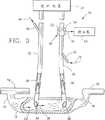
図1は、静脈管出口から下流にあるシャント内の動脈管入口と、静脈管内の注入ポートと、動脈管用のセンサとを備える透析装置に、動脈と静脈の管を経て接続されている動静脈シャントの線図である。
図1Aは、図1の装置に対する希釈曲線を示す。
図2は、動脈管に対して第2のセンサを付加している図1の変形例を示す。
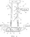
図3は、動脈センサの上流で動脈管の注入ポートを付加している図1の第2の変形例を示す。
図3Aは、図3の装置に対する希釈曲線を示す。
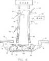
図4は、図3の装置に図2に示された型式の第2の動脈センサを付加している図1の第3変形例を示す。
図5は、静脈管と動脈管の各々に対して1つづ、計2つ付加的なセンサを組み入れている図1の第4変形例を示す。
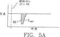
図5Aと図5Bは、図5の装置に対する希釈曲線を示す。
図6は、静脈管出口の上流にあるシャント内の動脈管入口と、静脈管内の注入ポートと、動脈管用のセンサと、このセンサの上流にある動脈管にキャリブレーションポートを持つ透析装置に、動脈と静脈の管を経て接続されている動静脈シャントを示す本発明の第2の実施例の線図である。
図7は、図6の装置の変形例の線図であり、図6のキャリブレーションポートが静脈管注入ポートの下流にある静脈管センサによって置き換えられている。
好ましい実施例の説明
今ここに、本発明による透析シャント内の血流を決定するプロセスをより詳細に検討する。図1に、血管12への動脈と静脈の逆接続を使用している患者血液透析システム10が示されている。この逆接続は、シャントの上流端14で患者の動脈16に接続されると共に、その下流端18で患者の静脈20に接続されている動静脈シャントとして図示されている。このシャントは、人工血管または生の血管であり、手術によって動脈16と静脈20との間に移動されている。血管12における血流の方向は、矢印22によって示される。そして、決定されるべきものはこの血流である。上記血管12と従来型の血液透析装置24との間に、動脈ラインすなわち動脈管26が接続されている。この動脈管26は、上記透析装置によって処理用の血液を引くために、シャント12中に入口28を持っている。動脈ライン26内の血液が流れる方向は、矢印30によって示されている。
また、上記透析装置24とシャント12との間に、静脈ラインすなわち静脈管32が接続されている。この静脈管32は透析装置24から出る処理された血液をシャントへ導き戻す。静脈ライン32は、動脈ライン入口28の上流のシャント12内に配置された出口34を持っている。動脈ライン32での処理された血流の方向は、矢印36によって示される。矢印38によって示されるように、出口34から出る処理された血液は、下流に、すなわち主たる流れ22の方向に、入口28に向かって移動し、この入口28では処理された血液38の幾らかは動脈ライン26によって収集される。
本発明によると、処理される血液の物理的性質と異なるものを持つインディケータ物質を選択し、そのインディケータ物質を注入ポート40を経て静脈ライン32の中に注入することによって、シャント内の血流の測定が得られる。好ましい実施例では、矢印42によって示されるこの物質は、血液と等張の塩性溶液であるが、異なる音波速度特性を持っている。他の指示物質は、例えば、加熱された血液または冷却された血液であってもよい。この注入されたインディケータは、静脈ラインの中で血流36と混合され、シャント12に戻されて、そこでシャント流22と混合される。インディケータの一部分は、矢印30によって示されるように、上記動脈血液ラインによってシャントから回収される。
センサー50は、注入ポート40の下流の位置に設けられ、図1に示すように、好ましくは動脈ライン26に配置される。好ましくは、このセンサは血液音速検知器であり、この血液音速検知器は音源52を備えて動脈ライン26を通過する血液を直接突き抜けて音波を音波レシーバ54に送る。この音波レシーバ54は、血液中の音波の速度に関連して出力信号を発生する。このような音速検知器は当該技術分野でよく知られており、その例として、アメリカ合衆国のニューヨーク州イサカ(Ithaca)のトランソニックシステムズ社(Transonic Systems,Inc.)によって製造されているとランソニック4x血管周囲プローブがある。このプローブでは、レシーバ54は検知器58に向けられたライン56上に出力信号を発信する。上記検知器58は上記ライン56を経て供与される信号を測定かつ評価する。この検知器は、信号を記録すると共に、シャント12内に血流および透析装置24を通る血流を決定するために、センサの出力信号を血液濃度信号に変換するための上述の計算を行う。もし、透析装置24内の血流がシャント12内の流れに比べて比較的小さければ、センサー50によって行なわれる測定はシャントの流れを誇張する結果となる。
より詳細には、シャント12の中の血流Qは、センサ50によって得られる希釈線の下降部の面積を計算することによって、等式1に従って計算され得る。このような曲線の一例は図1Aに示され、図中、動脈血流の中の音波の速度は、曲線59によって示される。時間0で、インディケータ物質がポート40において注入される。その後しばらくして、このインディケータによって引き起こされる音速の変化はセンサ50で検知され、曲線59では窪み59a、または希釈面積によって示される。領域59a内の希釈曲線59の下降部の面積は、等式2に記述されている面積Sartである。
図2に示されるように、第2の血流センサ60は動脈ライン26上に設けられると共にライン62を経て検知器58に接続されている。この第2のセンサは、トランソニックシステムズ社によって製造されたHT109締付型流量計のような血流センサである。そして、この第2のセンサは、ライン26の血流Qdialを測定するために使用されて、この血流Qdialは、シャントの血流の決定の精度を上げるために、図1の実施例に従って計算される流れの合計から差し引かれる。この改善された精度は、等式2と3に従って得られる。センサ60はセンサ50と分離して示されているが、望まれるなら、この2つのセンサは単一ユニットに組み込まれてもよい。
本発明のもう1つの変形例は、図3に示される。図3は、ライン72によって示されるように、キャリブレーションインディケータ物質を注入するための注入ポート70を動脈ライン26に追加してある以外、図1と同じである。この注入ポート70は、インディケータ物質72がライン26内の血流の全てと混合されるように、センサ50の上流に配置されている。ポート70でのキャリブレーションインディケータ物質の注入は、センサ50によって検知されると、血流中の音速の変化に従って、図3Aの74で示される対応希釈曲線をつくる。そして、この希釈曲線は検知器58によって記録される。この検知器は、等式4にしたがって、曲線74の下降部の面積Scalとインディケータ物質72の既知の体積Vcalとからライン26内の血流Qdialを決定する。次に、この血流Qdialは、シャント血流測定の精度を増すために、図1に従って計算された全血流から、等式6に従って差し引かれる。
本発明のもう1つの実施例は図4に示される。図4は図1,2,3の測定の全てを含む。それ故に、図4の装置は、音源52とライン56で検知器58に信号を送る音波レシーバ54とを備えたセンサ50を含み、また、ライン62を経て検知器58に接続されている血流センサ60を含むと共に、キャリブレーションインディケータ物質72を受けるためのキャリブレーション注入ポート70を含んでいる。ライン62上の出力信号は、透析血流Qdialを測定するためのものである。インディケータ72は、上述したように、キャリブレーション注入であり、既知の血流Qdialに関連した音速の相対的変化が、センサ50によって測定される。インディケータ物質42のポート40への注入と、同じインディケータ物質72のポート70への注入とに対応する音速の相対的変化は、センサ50によって記録される。その結果、これらの注入による動脈ライン26内の音速の相対的変化は、等式5に従って検知器58で計算されることができ、正確なシャント血流測定を得る。
さらに本発明のもう1つの実施例が、図5に示されている。この図は、図2の実施例と類似しているが、静脈ラインすなわち静脈管32上に配置されたセンサ80を追加している。センサ80は音波トランスミッタ82と音波レシーバ84とを含み、このレシーバは検知器58に接続されている出力ライン86上に出力信号を発生させる。センサ80の使用によって動脈ライン26での付加的なキャリブレーション注入の必要が無くなる。この付加的な音波源82とレシーバ84は音速源52とレシーバ54とに匹敵する。そして、センサ80は注入ポート40の下流の静脈ライン32に配置される。その結果、インディケータ物質42の全ては、センサ80を突き抜けて流れ、希釈曲線88をつくる(図5A)。ポート40で行われる注入は、静脈ライン32の中の血流とのみ混合され、それ故にセンサ80をキャリブレートするのに役立つ。この同一の注入が、後に、インディケータ物質がシャン血管12を通過した後、同等なセンサ50に希釈曲線89(図5B)を生じさせる。そして、一部は動脈ライン26の中に再循環される。シャント血流Qshuntの計算が等式8に従って行なわれる。
本発明の第2の実施例が、図6に言及して示される。この実施例は、透析装置ラインの「通常」の接続を使用している間に、新たに純化された血液の好ましくない再循環の測定を提供する。この実施例では、それ故、透析装置24は、シャント12と、入口92から上記透析装置に導く動脈ライン90とを経て患者の血管系に接続されている。同様にして、この装置は静脈ライン94によってシャント12に接続されている。この静脈ライン94は、純化された血液を透析装置から出口96を通ってシャントに供給する。動脈ライン90の中の血流の方向は矢印98によって示され、静脈ライン94の中の血流の方向は矢印100によって示されている。
出口96はシャント12内の入口92から下流に存在するが、それにも拘わらず、このような「通常」の接続によって、矢印102によって示されるように、純化された血液の好ましくない再循環が生じ得る。このようにして、純化された血液は、血管12内の上流方向に流れる可能性があり、かつ、入口92で拾われて透析装置を通り再循環し、次に、このような再循環される血液は動脈血流98の一部を形成し得る。
この再循環を測定するために、血液の物性と異なる物性を持つインディケータ物質が選択され、注入ポート104を通って静脈ライン94内に注入される。好ましい実施例では、矢印106によって示されるインディケータ物性は、血液と等張の塩性溶液であるが、異なる音速特性を持っている。このようなインディケータの注入は、静脈ライン94の中で血液を希釈させる。そして、もし再循環が存在するならば、希釈された血液の幾らかは動脈ライン90に現れ、結果として音速の変化を生じ、その変化は音源112と音波レシーバ114を持つセンサ110によって記録される。このレシーバ114は、前述の実施例で説明された型式の検知器118にライン116を経て接続される。この検知器は、測定と評価の装置として機能し、受け取った信号を記録し、インディケータ物質の注入から生じる希釈曲線の下降部の面積を計算すると共に、上述の等式に規定された計算を行う。
インディケータ物質106と同じであるインディケータ物質120の付加的なキャリブレーション注入は、センサ110の上流にある動脈ライン90のポート122を経て行われる。動脈ライン90の血液の全てはセンサ110を通過するので、122で注入されたインディケータ物質はこの動脈血流とのみ混合され、かつ、その結果生じて検知器118によって記録される希釈曲線は、希釈曲線の下降部の面積を計算し、続いて再循環のフラクションの決定を等式10に従って計算することによって、システムをキャリブレーションするのを可能にする。
もし、再キャリブレーション注入の必要性を回避することが望まれるならば、図7に示すように、図6の装置を変形したものが与えられる。この変形では、音速源132と音速レシーバ134を有する付加的なセンサ130が、静脈ライン94上に設けられる。このレシーバ134はライン136を経て検知器118に接続されている。上記センサ130はセンサ110に匹敵し、注入ポート104の下流に配置されている。その結果、ポート104に注入されたインディケータ物質106と同じく、透析装置24からの血液は全て、センサ130を通過する。このセンサは動脈血100で希釈曲線を測定し、次に同じ注入が動脈ライン90を通る流れ98で希釈を生み出す。センサ110はインディケータ物質を検知して、その結果得られる信号を検知器118に提供し、上記信号から再循環が等式11に従って計算され得る。なお、第1の実施例とその様々な変形例に関しては上に概要が述べれており、図1乃至図5に言及して記載されている。
本発明は好ましい実施例として記載されているが、本発明の真の精神と範囲から逸脱すること無しに変更や修正が為され得ると理解される。BACKGROUND OF THE INVENTION The present invention relates to the field of renal dialysis processes, and more particularly to an apparatus for measuring arteriovenous shunt blood flow and unwanted recirculation during hemodialysis.
Dialysis is a device in which an artificial kidney replaces the function of the patient's kidney. Blood is transferred from the patient's vasculature via the arterial line, passed through the dialyzer, and returned to the patient via the venous line for normal circulation through the patient's vasculature. The majority of dialysis patients have an arteriovenous shunt implanted at a high blood flow location, which collects blood from the portion of the shunt close to the artery and is downstream of this location. It becomes easy to return the purified blood to near the vein side of the shunt. In some cases, shunt clots and stenosis and the resulting reduction in blood flow require surgery, which is expensive and pressureful for the patient. In situations of low blood flow in the shunt, or if there are any other problems with venous outflow, a portion of freshly dialyzed blood from the venous return line flows directly into the arterial collection line and is filtered again Is done. If this undesirable degree of direct recirculation is quite severe, some of the blood is repeatedly filtered and the patient's remaining blood is not sufficiently filtered to provide sufficient dialysis for the patient.
Currently, color-coded sonography is used as one of the methods for measuring shunt blood flow. This method is very expensive and involves operation by highly qualified specialists. Therefore, this measurement is made only rarely, and the situation of reduced blood flow is overlooked when processing is performed without surgery.
Standard tests for undesired direct recirculation require three blood samples while the patient is dialyzing. This method requires a blood sample from the patient, takes time for the nurse, and requires an expensive laboratory. In general, dialysis patients have a lower hematocrit than normal people, and losing blood puts the patient at greater risk, so this is not very satisfactory.
Another technique involves the intravenous injection of saline solution to quantitatively detect recirculation and records changes in the optical properties of blood. This technique remains controversial on the question of whether recirculation is reduced quantitatively enough to ensure intervention.
SUMMARY OF THE INVENTION The present invention avoids the problems encountered by the aforementioned methods and techniques by providing an accurate determination of shunt blood flow and undesired recirculation at a low cost.
The blood flow Q measured by the dilution method is given by the following formula (ACGuyton Textbook of Medical Physiology, 6th edition, page 287, 1981).
Q = V / S (Equation 1)
Where V is the amount of indicator injected and S is the area of the descending portion of the dilution curve, which is the mean concentration of the indicator in the blood during the curve multiplied by the duration of the curve. equal.
The dilution curve is obtained by measuring changes in physical parameters of blood over a period of time and expressing the resulting changes on coordinates. For example, if the measured blood parameter is the speed of sound, by injecting an indicator, such as a salt solution, having a speed of sound different from that of the blood, the indicator changes to the measured parameter as it passes the sensor position. Occurs. The indicator dilutes the blood and produces a sound velocity curve that is a measure of this dilution. Injection of a saline solution is convenient to produce measurable blood parameters such as changes in sound speed, but other blood parameter changes can also be applied. Thus, changes in temperature, electrical impedance, optical properties, etc. can also be used as indicators to create a dilution curve. However, for the purposes of this disclosure, salt solutions are mainly used as indicators.
In order to facilitate the measurement of shunt blood flow according to the present invention, the blood line connection is reversed. That is, the arterial inlet that transfers blood from the patient for dialysis is placed downstream (rather than upstream as usual) of the shunt vein outlet. A certain amount of indicator, eg saline solution (Vven), is injected into the venous line. In the venous line, the indicator is mixed with the dialyzer blood flow Qdial and this mixture is fed to the shunt. There, this mixture is merged with the blood flow (Qshunt) in the shunt. The shunt blood flow (Qshunt) can be calculated from
Qshunt + Qdial = Vven / Sart (Equation 2)
Or
Qshunt + Vven / Sart-Qdial (Equation 3)
Equation 3 shows that if the blood flow Qdial through the dialyzer is measured and the absolute concentration Sart of the indicator in the arterial blood line is recorded, the blood flow Qshunt through the shunt can be calculated.
In some methods applicable to hemodialysis, the sensor is anchored to the outer surface of an artery or vein line or tube. However, it is difficult to measure the absolute concentration of the indicator in the blood passing through the hemodialysis tube. For example, if a sonic sensor is used to record changes in protein concentration in the blood due to the injection of a salt indicator, the sound wave must pass through both the tube and the blood. The measurements recorded for absolute sound velocity are not only influenced by blood, but also by the unknown acoustic properties of the tube. The same problem occurs when an optical sensor is attached to the tube. That is, the recorded amplitude of the light beam is not only a function of the hemoglobin concentration, but also a function of the tube characteristics.
This problem is solved by injecting additional calibration with the same indicator. This indicator is injected upstream of the point where the arterial line is measured. The equation in this case is
Qdial = Vcal / Scal (Equation 4)
Here, Vcal is the known amount of the indicator in the calibration injection, and Scal is the area of the descending portion of the resulting dilution curve. This area is the average concentration of the indicator in the blood over the period of this curve multiplied by the period of the curve.
From equations 2 and 4, the formula for shunt blood flow is
Qshunt = Qdial ((Vven / Vcal) x Scal / Sart-1) (Equation 5)
Or
Qshunt = (Vven / Sart−Vcal / Scal) (Equation 6)
Equation 5 is appropriate if the blood flow in the tube can be accurately measured. The ratio Scal / Sart shows that the recorded dilution area is only required to be proportional to the relative change in concentration in this case. Assuming that the tube characteristics are constant during the measurement, the value of this ratio can be calculated with high accuracy for most types of sensors, including sonic sensors, optical sensors and the like.
If the blood flow in the tube is unknown, but absolute concentration is measured, Equation 6 can be used. This absolute concentration is measured, for example, by collecting blood from the arterial blood line and using an optical densitometer for optical staining dilution measurements.
To avoid the need for calibration injection, an additional sensor equivalent to the arterial line sensor is placed on the venous line downstream from the venous injection position of the indicator. In this case, the injected indicator mixes with the venous line flow. So by analogy with the calibration injection in Equation 4,
Qdial = Vven / Sven (Equation 7)
Where Sven is the area of the descending part of the dilution curve and is calculated as the average concentration of the indicator in the blood during the curve period multiplied by the period of the curve. The area Sart is created from the same injection. By substituting into Equation 5, the formula for blood flow is
Qshunt = Qdial (Sven / Sart-1) (Equation 8)
As an alternative to the foregoing, the amount of blood recirculation is measured while the shunt dialysis blood line is normally connected. In a normal connection, the inlet to the arterial line is upstream of the shunt and the outlet of the venous line connection is downstream of the shunt. After injecting the indicator into the venous line with this “normal” connection, the sudden appearance of the indicator in the arterial line is an indication of the presence of recirculation. The amount of recirculation is the fraction (fraction) of blood in the freshly filtered venous line that recirculates toward the arterial line. This amount is then equal to the ratio of the volume (Vrec) of the indicator recirculated to the arterial line to the volume (Vven) injected into the venous line.
The amount Vrec of the recirculated indicator is equal to the product of the blood flow Qdial in the arterial line and the area Srec of the descending portion of the dialysis blood flow recirculated concentration dilution curve.
Vrec = Srec × Qdial (Equation 9)
The same problem remains as described in equations 2 and 3 for the evaluation of Srec. That is, it is difficult to measure the indicator concentration through the tube. As discussed above with respect to Equation 4, this problem is avoided by making an additional calibration injection of the same indicator into the arterial line upstream of where the measurements are made. From equations 4 and 9, the recirculation fraction is
Vrec / Vven = (Vcal / Vven) x Srec / Scal (Equation 10)
The ratio Srec / Scal in
To avoid the need for calibration injection, an additional sensor equivalent to the arterial line sensor may be placed downstream of the injection position of the indicator in the vein. In this case, the injected indicator is mixed with the flow of the venous line tube. Thus, by analogy with the calibration injection in Equation 7,
Vrec / Vven = Srec / Sven (Equation 11)
In short, shunt blood flow can be measured by reversing the arterial and venous lines. The arterial inlet that transfers blood from the patient's vasculature is located downstream of the venous outlet in the shunt. This venous outlet returns the treated blood to the patient's vasculature. Indicator material is injected into the injection port of the venous tube and changes in the physical properties of blood are monitored in the arterial line. These changes are recorded, and the resulting area of the descending portion of the dilution curve provides a measure of blood flow in the shunt and tubing. The indicator used for this purpose is any substance or blood treatment that changes the physical properties of the blood. For example, it is a salt solution, preferably a salt solution of known concentration, or a quantity of heated or cooled blood. The change in characteristics is measured by a known sensor such as a sound speed sensor, an electrical impedance sensor, an optical sensor, a thermal sensor, an isotope sensor, or the like. The blood flow relationship is then calculated according to the above equation.
The tubing used to direct blood from the patient to the dialyzer may require calibration measurements due to errors in blood flow measurements. Calibration injection is used for calibration measurement, and blood concentration measurement is used if blood flow is unknown. Additional sensors may be provided on the venous line downstream of the venous infusion port to avoid the need for calibration infusion.
Blood recirculation can also be measured using an arterial line placed in a shunt upstream of the venous outlet. In this case, the indicator is injected into the injection port at the venous line outlet (as before) and the blood properties are monitored at the arterial line. Calibration injection may be given at an injection port in the arterial line upstream of the arterial tube monitoring device. Alternatively, a second blood property monitoring device can be provided in the venous tube downstream of the venous infusion port to avoid calibration infusion.
[Brief description of the drawings]
The foregoing and additional objects, features and advantages of the present invention will become apparent to those skilled in the art from the following detailed description, taken in conjunction with the accompanying drawings, of preferred embodiments of the invention.
FIG. 1 shows an arteriovenous vein connected to a dialysis apparatus including an arterial tube inlet in a shunt downstream from the venous tube outlet, an infusion port in the venous tube, and a sensor for the arterial tube via arterial and venous tubes. FIG.
FIG. 1A shows a dilution curve for the apparatus of FIG.
FIG. 2 shows a variation of FIG. 1 in which a second sensor is added to the arterial tube.
FIG. 3 shows a second variation of FIG. 1 with an arterial tube injection port added upstream of the arterial sensor.
FIG. 3A shows a dilution curve for the apparatus of FIG.
FIG. 4 shows a third variant of FIG. 1 in which a second arterial sensor of the type shown in FIG. 2 is added to the device of FIG.
FIG. 5 shows a fourth variation of FIG. 1 incorporating two additional sensors, one for each of the venous and arterial tubes.
5A and 5B show dilution curves for the apparatus of FIG.
FIG. 6 illustrates a dialysis machine having an arterial tube inlet in a shunt upstream of the venous tube outlet, an infusion port in the venous tube, a sensor for the arterial tube, and a calibration port in the arterial tube upstream of the sensor. FIG. 4 is a diagram of a second embodiment of the present invention showing an arteriovenous shunt connected via an arterial and venous tube.
FIG. 7 is a diagram of a variation of the apparatus of FIG. 6, wherein the calibration port of FIG. 6 is replaced by a venous vessel sensor downstream of the venous vessel infusion port.
Herethe preferred embodiment of the description <br/> now consider a process for determining the blood flow of the dialysis in the shunt according to the present invention in more detail. FIG. 1 shows a
Further, a venous line, that is, a
According to the present invention, by selecting an indicator material having a physical property different from that of the blood to be treated and injecting the indicator material into the
A
More specifically, the blood flow Q in the
As shown in FIG. 2, the second
Another variation of the present invention is shown in FIG. FIG. 3 is the same as FIG. 1 except that an
Another embodiment of the present invention is shown in FIG. FIG. 4 includes all of the measurements of FIGS. Therefore, the apparatus of FIG. 4 includes a
Yet another embodiment of the present invention is shown in FIG. This figure is similar to the embodiment of FIG. 2, but with the addition of a
A second embodiment of the present invention is shown with reference to FIG. This example provides an undesired recirculation measurement of freshly purified blood while using a “normal” connection on the dialyzer line. In this embodiment,
Although the
In order to measure this recirculation, an indicator substance having a physical property different from that of blood is selected and injected into the
An additional calibration injection of
If it is desired to avoid the need for recalibration injection, a modification of the apparatus of FIG. 6 is provided, as shown in FIG. In this variation, an
While this invention has been described as a preferred embodiment, it is understood that changes and modifications can be made without departing from the true spirit and scope of this invention.
Claims (8)
Translated fromJapanese上記血流センサー手段に接続された記録手段を備え、上記血液供給ラインにインジケータを導入した結果として、上記取り除かれた血液の量を登録し、
上記記録手段に接続された計算機手段を備え、上記取り除かれた血液内のインジケータの量の上記登録から上記シャント血流の流量を計算することを特徴とする心臓血管システムに接続された血液透析のシャント血流を決定するための装置。Blood flow sensor means connected to a blood intake line in the hemodialysis blood circulation system, wherein the hemodialysis blood circulation system is adapted to supply blood flow through the blood supply line to an upstream position of the shunt. In the shunt, the supplied blood is mixed with the shunt blood flow, the circulation system removes the blood from the downstream position in the shunt via the intake line, and the removed blood is removed in the shunt. Part of the supply blood mixed with the bloodstream,
Recording means connected to the blood flow sensor means, registering the amount of removed blood as a result of introducing an indicator into the blood supply line;
A hemodialysis machine connected to the cardiovascular system, comprising computer means connected to the recording means, and calculating the flow rate of the shunt blood flow from the registration of the amount of indicator in the removed blood. A device for determining shunt blood flow.
上記血液透析血液循環システムの血流を記録するために上記システムに接続されると共に、シャント血流の計算の精度を増大させるために上記計算機手段に接続された血流インジケータ手段を更に備えていることを特徴とする装置。The apparatus of claim 1.
Blood flow indicator means connected to the system for recording blood flow of the hemodialysis blood circulation system and connected to the computer means for increasing the accuracy of the shunt blood flow calculation. A device characterized by that.
上記記録手段は、上記血流センサー手段から上流にインジケータを導入した結果として、上記インジケータの量を登録する手段であると共に、上記シャント血流の計算の精度を増大させる手段を更に含んでいることを特徴とする装置。The apparatus of claim 1.
The recording means is means for registering the amount of the indicator as a result of introducing the indicator upstream from the blood flow sensor means, and further includes means for increasing the accuracy of the calculation of the shunt blood flow. A device characterized by.
上記血液透析血液循環システムの血流を記録するために上記システムに接続されると共に、上記シャント血流の計算の精度を増大させるために上記計算機手段に接続された血流インジケータ手段を更に備えていることを特徴とする装置。The apparatus of claim 3.
Blood flow indicator means connected to the system for recording blood flow of the hemodialysis blood circulation system and connected to the computer means for increasing the accuracy of the calculation of the shunt blood flow. A device characterized by comprising.
上記血液透析血液循環システムに接続されると共に、上記シャントに血液を供給する前に上記血液透析血液循環システム内の血液の量を記録する上記記録手段に接続された第2血流センサー手段を更に備え、上記シャント血流の計算の精度を増大させることを特徴とする装置。The apparatus of claim 1.
A second blood flow sensor means connected to the hemodialysis blood circulation system and connected to the recording means for recording the amount of blood in the hemodialysis blood circulation system before supplying blood to the shunt. An apparatus for increasing the accuracy of the calculation of the shunt blood flow.
上記血液透析血液循環システムの血流を記録するために上記システムに接続されると共に、上記シャント血流の計算の精度を増大させるために上記計算機手段に接続された血流インジケータ手段を更に備えていることを特徴とする装置。The apparatus of claim 5.
Blood flow indicator means connected to the system for recording blood flow of the hemodialysis blood circulation system and connected to the computer means for increasing the accuracy of the calculation of the shunt blood flow. A device characterized by comprising.
上記血流センサー手段は、熱センサーと光学センサーと電気インピーダンスセンサーと超音波センサーの内の1つであることを特徴とする装置。The apparatus of claim 1.
The blood flow sensor means is one of a thermal sensor, an optical sensor, an electrical impedance sensor, and an ultrasonic sensor.
上記第2血流センサー手段は、熱センサーと光学センサーと電気インピーダンスセンサーと超音波センサーの内の1つであることを特徴とする装置。The apparatus of claim 5.
The second blood flow sensor means is one of a thermal sensor, an optical sensor, an electrical impedance sensor, and an ultrasonic sensor.
Applications Claiming Priority (3)
| Application Number | Priority Date | Filing Date | Title |
|---|---|---|---|
| US08/305,953US5685989A (en) | 1994-09-16 | 1994-09-16 | Method and apparatus to measure blood flow and recirculation in hemodialysis shunts |
| US305,953 | 1994-09-16 | ||
| PCT/US1994/013163WO1996008305A1 (en) | 1994-09-16 | 1994-11-18 | Blood flow measurement method in hemodialysis shunts |
Publications (2)
| Publication Number | Publication Date |
|---|---|
| JPH10505766A JPH10505766A (en) | 1998-06-09 |
| JP3627042B2true JP3627042B2 (en) | 2005-03-09 |
Family
ID=23183086
Family Applications (1)
| Application Number | Title | Priority Date | Filing Date |
|---|---|---|---|
| JP51014396AExpired - Fee RelatedJP3627042B2 (en) | 1994-09-16 | 1994-11-18 | Blood flow measuring device for hemodialysis shunt |
Country Status (7)
| Country | Link |
|---|---|
| US (1) | US5685989A (en) |
| EP (1) | EP0781161B1 (en) |
| JP (1) | JP3627042B2 (en) |
| CA (1) | CA2198601C (en) |
| DE (1) | DE69429877T2 (en) |
| ES (1) | ES2171524T3 (en) |
| WO (1) | WO1996008305A1 (en) |
Families Citing this family (118)
| Publication number | Priority date | Publication date | Assignee | Title |
|---|---|---|---|---|
| US6740036B1 (en) | 2000-07-18 | 2004-05-25 | Lian-Pin Lee | Optical and ultrasound probe for monitoring blood volume changes |
| US5644240A (en) | 1992-09-30 | 1997-07-01 | Cobe Laboratories, Inc. | Differential conductivity hemodynamic monitor |
| US6514419B2 (en)* | 1994-09-16 | 2003-02-04 | Transonic Systems, Inc. | Method to measure blood flow and recirculation in hemodialysis shunts |
| US6153109A (en) | 1994-09-16 | 2000-11-28 | Transonic Systmes, Inc. | Method and apparatus to measure blood flow rate in hemodialysis shunts |
| DE19528907C1 (en)* | 1995-08-05 | 1996-11-07 | Fresenius Ag | Haemodynamic parameter measurement equipment for extracorporeal blood circulation appts. |
| DE19541783C1 (en)* | 1995-11-09 | 1997-03-27 | Fresenius Ag | Method for operating a blood treatment device for determining hemodynamic parameters during an extracorporeal blood treatment and device for determining hemodynamic parameters during an extracorporeal blood treatment |
| IT1288767B1 (en)* | 1996-10-18 | 1998-09-24 | Hospal Dasco Spa | METHOD OF DETERMINING THE VALUE OF THE RECIRCULATION OF A SUSPENSION SUBJECT TO TREATMENT. |
| US6746415B1 (en)* | 1996-10-23 | 2004-06-08 | Hema Metrics, Inc. | Method of blood constituent monitoring using improved disposable extracorporeal conduit |
| US6117099A (en)* | 1996-10-23 | 2000-09-12 | In-Line Diagnostics Corporation | System and method for noninvasive hemodynamic measurements in hemodialysis shunts |
| EP0944362A4 (en)* | 1996-10-23 | 2001-11-21 | In Line Diagnostics Corp | System and method for noninvasive hemodynamic measurements in hemodialysis shunts |
| DE19746367C2 (en)* | 1996-11-30 | 1999-08-26 | Fresenius Medical Care De Gmbh | Method for in-vivo determination of parameters of hemodialysis and device for carrying out the method |
| DE19702441C1 (en)* | 1997-01-24 | 1998-02-26 | Fresenius Medical Care De Gmbh | Dialysis recirculation monitoring |
| US5919135A (en)* | 1997-02-28 | 1999-07-06 | Lemelson; Jerome | System and method for treating cellular disorders in a living being |
| DE19739099C1 (en)* | 1997-09-06 | 1999-01-28 | Fresenius Medical Care De Gmbh | Monitoring of a blood container inlet during external blood treatment |
| US6189388B1 (en) | 1997-11-12 | 2001-02-20 | Gambro, Inc. | Access flow monitoring using reversal of normal blood flow |
| US6648845B1 (en) | 1998-01-07 | 2003-11-18 | Fresenius Medical Care North America | Method and apparatus for determining hemodialysis parameters |
| US6177049B1 (en) | 1998-06-10 | 2001-01-23 | Dsu Medical Corporation | Reversing flow blood processing system |
| US6167765B1 (en) | 1998-09-25 | 2001-01-02 | The Regents Of The University Of Michigan | System and method for determining the flow rate of blood in a vessel using doppler frequency signals |
| US6575927B1 (en)* | 1998-09-25 | 2003-06-10 | The Regents Of The University Of Michigan | System and method for determining blood flow rate in a vessel |
| US6726647B1 (en) | 1998-10-23 | 2004-04-27 | Gambro Ab | Method and device for measuring access flow |
| EP2198900B1 (en) | 1998-10-23 | 2016-02-10 | Gambro Lundia AB | Method and device for detecting access recirculation |
| DE19859811C2 (en)* | 1998-12-23 | 2001-05-10 | Hilekes Guido | Contrast agent injection system |
| DE19901078C1 (en) | 1999-01-14 | 2000-02-17 | Polaschegg Hans Dietrich | Monitoring system for fistula or graft has instruments to detect pulse from patient's heart or external blood circulation pump |
| US6986744B1 (en) | 1999-02-02 | 2006-01-17 | Transonic Systems, Inc. | Method and apparatus for determining blood flow during a vascular corrective procedure |
| DE19917197C1 (en)* | 1999-04-16 | 2000-07-27 | Fresenius Medical Care De Gmbh | Method to determine blood flow in vessel entrance of haemodialysis unit; involves measuring arterial and venous pressures when vessel entrance is open to allow blood flow and closed to prevent blood flow |
| US6319465B1 (en) | 1999-06-03 | 2001-11-20 | Dsu Medical Corporation | Reversing flow blood processing system having reduced clotting potential |
| US6868739B1 (en) | 1999-10-19 | 2005-03-22 | Transonic Systems, Inc. | Method and apparatus to measure blood flow by an introduced volume change |
| US6890315B1 (en)* | 2000-05-23 | 2005-05-10 | Chf Solutions, Inc. | Method and apparatus for vein fluid removal in heart failure |
| US6533747B1 (en)* | 2000-05-23 | 2003-03-18 | Chf Solutions, Inc. | Extracorporeal circuit for peripheral vein fluid removal |
| US6887214B1 (en) | 2000-09-12 | 2005-05-03 | Chf Solutions, Inc. | Blood pump having a disposable blood passage cartridge with integrated pressure sensors |
| US6468241B1 (en) | 2000-10-26 | 2002-10-22 | Chf Solutions, Inc. | Artificial kidney set with electronic key |
| US6585675B1 (en)* | 2000-11-02 | 2003-07-01 | Chf Solutions, Inc. | Method and apparatus for blood withdrawal and infusion using a pressure controller |
| US6689083B1 (en) | 2000-11-27 | 2004-02-10 | Chf Solutions, Inc. | Controller for ultrafiltration blood circuit which prevents hypotension by monitoring osmotic pressure in blood |
| US6706007B2 (en)* | 2000-12-29 | 2004-03-16 | Chf Solutions, Inc. | Feedback control of ultrafiltration to prevent hypotension |
| US6773412B2 (en)* | 2001-04-13 | 2004-08-10 | Chf Solutions, Inc. | User interface for blood treatment device |
| US20080027298A1 (en)* | 2001-05-22 | 2008-01-31 | Alfred E. Mann Institute For Biomedical Engineering At The University Of Southern Californ | System for Repetitive Measurements of Cardiac Output in Freely Moving Individuals |
| US7474906B2 (en)* | 2001-05-22 | 2009-01-06 | Alfred E. Mann Institute For Biomedical Engineering At The University Of Southern California | Method for dye injection for the transcutaneous measurement of cardiac output |
| US8337444B2 (en)* | 2001-05-22 | 2012-12-25 | Alfred E. Mann Institute For Biomedical Engineering At The University Of Southern California | Measurement of cardiac output and blood volume by non-invasive detection of indicator dilution for hemodialysis |
| US6757554B2 (en)* | 2001-05-22 | 2004-06-29 | Alfred E. Mann Institute For Biomedical Engineering At The University Of Southern California | Measurement of cardiac output and blood volume by non-invasive detection of indicator dilution |
| US6746408B2 (en)* | 2001-05-29 | 2004-06-08 | Transonic Systems Inc. | Method of blood flow measurement in arterio-venous hemodialysis shunts by indicator dilution |
| ITMI20011395A1 (en)* | 2001-06-29 | 2002-12-29 | Gambro Dasco Spa | METHOD AND DEVICE FOR DETECTION OF VENOUS NEEDLE FROM A PATIENT DURING AN EXTRACORPOREAL BLOOD TREATMENT IN A MACHINE |
| US7241272B2 (en) | 2001-11-13 | 2007-07-10 | Baxter International Inc. | Method and composition for removing uremic toxins in dialysis processes |
| SE0200370D0 (en)* | 2002-02-08 | 2002-02-08 | Gambro Lundia Ab | Method and apparatus for determining access flow |
| US6796955B2 (en)* | 2002-02-14 | 2004-09-28 | Chf Solutions, Inc. | Method to control blood and filtrate flowing through an extracorporeal device |
| AU2003211060A1 (en)* | 2002-02-15 | 2003-09-09 | Eunoe, Inc. | Systems and methods for flow detection and measurement in csf shunts |
| US10155082B2 (en) | 2002-04-10 | 2018-12-18 | Baxter International Inc. | Enhanced signal detection for access disconnection systems |
| US7138088B2 (en)* | 2002-04-10 | 2006-11-21 | Baxter International Inc. | Access disconnection system and methods |
| US7052480B2 (en) | 2002-04-10 | 2006-05-30 | Baxter International Inc. | Access disconnection systems and methods |
| US7022098B2 (en)* | 2002-04-10 | 2006-04-04 | Baxter International Inc. | Access disconnection systems and methods |
| US20040254513A1 (en) | 2002-04-10 | 2004-12-16 | Sherwin Shang | Conductive polymer materials and applications thereof including monitoring and providing effective therapy |
| US7734326B2 (en)* | 2002-06-20 | 2010-06-08 | Brainlab Ag | Method and device for preparing a drainage |
| DE60336724D1 (en) | 2002-07-19 | 2011-05-26 | Baxter Healthcare Sa | SYSTEM FOR PERITONEAL DIALYSIS |
| DE10259437B3 (en)* | 2002-12-19 | 2004-09-16 | Fresenius Medical Care Deutschland Gmbh | Method and device for determining blood flow in a blood-carrying line |
| EP1930035A1 (en)* | 2003-01-28 | 2008-06-11 | Gambro Lundia AB | Apparatus for monitoring a vascular access |
| US8038639B2 (en) | 2004-11-04 | 2011-10-18 | Baxter International Inc. | Medical fluid system with flexible sheeting disposable unit |
| US8029454B2 (en) | 2003-11-05 | 2011-10-04 | Baxter International Inc. | High convection home hemodialysis/hemofiltration and sorbent system |
| WO2005049113A1 (en) | 2003-11-20 | 2005-06-02 | Gambro Lundia Ab | Method, apparatus and software program for measurement of a parameter relating to a heart-lung system of a mammal. |
| WO2005061043A1 (en)* | 2003-12-11 | 2005-07-07 | Gambro Lundia Ab | Switching device and apparatus for controlling flow of a fluid |
| US7303540B2 (en)* | 2004-04-26 | 2007-12-04 | Chf Solutions, Inc. | User interface for blood treatment device |
| JP4868772B2 (en)* | 2004-08-24 | 2012-02-01 | 日機装株式会社 | Blood purification equipment |
| US7261696B2 (en)* | 2004-09-09 | 2007-08-28 | Transonic Systems, Inc. | Method and apparatus for measuring cardiac output via an extracorporeal cardiopulmonary support circuit |
| JP2008515547A (en) | 2004-10-07 | 2008-05-15 | フレセニアス メディカル ケア ホールディングス インコーポレイテッド | Blood flow check valve and related systems and methods |
| US7758530B2 (en)* | 2004-11-10 | 2010-07-20 | Bard Access Systems, Inc. | Method for measuring recirculation in catheters |
| DE102005001051B4 (en)* | 2005-01-07 | 2007-10-31 | Fresenius Medical Care Deutschland Gmbh | Apparatus and method for detecting complications during extracorporeal blood treatment |
| WO2006123197A1 (en)* | 2005-05-18 | 2006-11-23 | Gambro Lundia Ab | An apparatus for controlling blood flow in an extracorporeal circuit. |
| JP4925159B2 (en)* | 2005-10-12 | 2012-04-25 | 日機装株式会社 | Blood purification equipment |
| WO2007084632A2 (en) | 2006-01-20 | 2007-07-26 | Alfred E. Mann Institute For Biomedical Engineering At The University Of Southern California | Measurement of cardiac output and blood volume by non-invasive detection of indicator dilution |
| DE502006009203D1 (en)* | 2006-01-30 | 2011-05-12 | Pulsion Medical Sys Ag | System for establishing a dilution site |
| RU2309668C1 (en)* | 2006-02-20 | 2007-11-10 | Александр Сергеевич Парфенов | Method and device for non-invasive measurement of function of endothelium |
| US7815588B2 (en)* | 2006-06-07 | 2010-10-19 | Paul Sakiewicz | Method and device for reversing lines in the procedure of hemodialysis |
| US20080108930A1 (en)* | 2006-11-03 | 2008-05-08 | The Regents Of The University Of Michigan | Methods and Systems for Determining Volume Flow in a Blood or Fluid Conduit, Motion, and Mechanical Properties of Structures Within the Body |
| US20080149563A1 (en)* | 2006-12-22 | 2008-06-26 | Renal Solutions, Inc. | Method of controlling dialysis using blood circulation times |
| FR2911417B1 (en)* | 2007-01-17 | 2009-02-27 | Gambro Lundia Ab | MONITORING THE VASCULAR ACCESS OF A PATIENT SUBJECTED TO SUCCESSIVE EXTRACORPOREAL BLOOD TREATMENT SESSIONS |
| US8631683B2 (en)* | 2007-02-06 | 2014-01-21 | Fresenius Medical Care Holdings, Inc. | Dialysis systems including non-invasive multi-function sensor systems |
| WO2009061769A1 (en)* | 2007-11-06 | 2009-05-14 | Alfred E. Mann Institute For Biomedical Engineering At The University Of Southern Califorina | Measurement of hematocrit and cardiac output from optical transmission and reflection changes |
| DE102007056475A1 (en)* | 2007-11-22 | 2009-06-04 | Fresenius Medical Care Deutschland Gmbh | A method and apparatus for determining recirculation in a fistula or cardiopulmonary recirculation, and a blood treatment apparatus having means for determining fistula recirculation or cardiopulmonary recirculation percentage |
| US20090192469A1 (en)* | 2008-01-24 | 2009-07-30 | Istvan Bognar | Devices and Methods for Development of a Scar Tissue Tunnel Track |
| US8057679B2 (en) | 2008-07-09 | 2011-11-15 | Baxter International Inc. | Dialysis system having trending and alert generation |
| US20100051552A1 (en) | 2008-08-28 | 2010-03-04 | Baxter International Inc. | In-line sensors for dialysis applications |
| US20100152544A1 (en)* | 2008-11-19 | 2010-06-17 | Spectrum Medical Limited | Cardiac monitoring system and method |
| ITMI20090400A1 (en)* | 2009-03-16 | 2010-09-17 | Datamed Srl | METHOD OF MEASURING THE SPEED OF A FLUID AND RELATIVE EQUIPMENT. |
| US8057400B2 (en) | 2009-05-12 | 2011-11-15 | Angiologix, Inc. | System and method of measuring changes in arterial volume of a limb segment |
| DE102009060668A1 (en) | 2009-12-28 | 2011-06-30 | Fresenius Medical Care Deutschland GmbH, 61352 | Apparatus and method for monitoring extracorporeal blood treatment |
| US8844359B2 (en) | 2010-12-03 | 2014-09-30 | Hema-Q, Inc. | Apparatus for noninvasive measurement of properties of a fluid flowing in a tubing having a smaller inner diameter passage |
| US8694271B2 (en) | 2010-12-03 | 2014-04-08 | Hema-Q, Inc. | Apparatus and method for non invasive measurement of properties of a fluid flowing in a flexible tubing or conduit |
| US9283315B2 (en) | 2011-02-08 | 2016-03-15 | Fresenius Medical Care Holdings, Inc. | Apparatus and method for real time measurement of a constituent of blood to monitor blood volume |
| US9333286B2 (en) | 2011-05-12 | 2016-05-10 | Fresenius Medical Care Holdings, Inc. | Medical tubing installation detection |
| US8836519B2 (en) | 2011-05-12 | 2014-09-16 | Fresenius Medical Care Holdings, Inc. | Determining the absence or presence of fluid in a dialysis system |
| US8714017B2 (en) | 2011-11-15 | 2014-05-06 | Hema-Q, Inc. | Apparatus for non-invasive determination of sound velocity in a liquid and determining a parameter of the liquid from the sound velocity |
| DE102012104461A1 (en) | 2012-05-23 | 2013-12-12 | B. Braun Avitum Ag | Medical device for extracorporeal blood treatment with multiple sensor units |
| US9415151B2 (en) | 2012-09-25 | 2016-08-16 | Fresenius Medical Care Holdings, Inc. | Blood flow reversal valves and related systems and methods |
| DE102013103220A1 (en)* | 2013-03-28 | 2014-10-02 | B. Braun Avitum Ag | Method and device for determining a recirculation state |
| DE102013103222A1 (en) | 2013-03-28 | 2014-10-02 | B. Braun Avitum Ag | Recirculation detection by bolus administration |
| EP2792377A1 (en) | 2013-04-15 | 2014-10-22 | Gambro Lundia AB | Medical infrastructure and medical monitoring apparatus for surveillance of patients over a plurality of extracorporeal blood treatment sessions |
| CN106460176B (en) | 2014-04-28 | 2020-02-07 | 凯普卓尼克技术公司 | Metallization of surfaces |
| WO2016207206A1 (en) | 2015-06-25 | 2016-12-29 | Gambro Lundia Ab | Medical device system and method having a distributed database |
| CN109803696B (en) | 2016-10-03 | 2022-08-05 | 甘布罗伦迪亚股份公司 | Measuring channel flow rate by using a blood processing machine |
| DE102016119259A1 (en)* | 2016-10-10 | 2018-04-12 | B. Braun Avitum Ag | Apparatus and method for recirculation measurement |
| AU2017381172A1 (en) | 2016-12-21 | 2019-06-13 | Gambro Lundia Ab | Medical device system including information technology infrastructure having secure cluster domain supporting external domain |
| JP7038358B2 (en)* | 2017-09-14 | 2022-03-18 | 株式会社アルチザンラボ | Blood purification device |
| JP7061509B2 (en) | 2018-04-26 | 2022-04-28 | 日機装株式会社 | Blood purification device |
| DE102018208538A1 (en) | 2018-05-30 | 2019-12-05 | Kardion Gmbh | Intravascular blood pump and process for the production of electrical conductors |
| DE102018208936A1 (en) | 2018-06-06 | 2019-12-12 | Kardion Gmbh | Determining device and method for determining a viscosity of a fluid |
| DE102018208945A1 (en) | 2018-06-06 | 2019-12-12 | Kardion Gmbh | An analysis device and method for analyzing a viscosity of a fluid |
| DE102018208929A1 (en) | 2018-06-06 | 2019-12-12 | Kardion Gmbh | A method of determining a flow rate of fluid flowing through an implanted vascular support system |
| DE102018208913A1 (en) | 2018-06-06 | 2019-12-12 | Kardion Gmbh | A method of operating an implanted ventricular assist device |
| DE102018208933A1 (en) | 2018-06-06 | 2019-12-12 | Kardion Gmbh | A method of determining a flow rate of fluid flowing through an implanted vascular support system |
| DE102018208899A1 (en)* | 2018-06-06 | 2019-12-12 | Kardion Gmbh | A method for determining the speed of sound in a fluid in the region of an implanted vascular support system |
| DE102018208862A1 (en) | 2018-06-06 | 2019-12-12 | Kardion Gmbh | Implantable vascular support system |
| DE102018208879A1 (en) | 2018-06-06 | 2020-01-30 | Kardion Gmbh | Method for determining a total fluid volume flow in the area of an implanted, vascular support system |
| DE102018210076A1 (en) | 2018-06-21 | 2019-12-24 | Kardion Gmbh | Method and device for detecting a state of wear of a cardiac support system, method and device for operating a cardiac support system and cardiac support system |
| WO2020154638A1 (en)* | 2019-01-25 | 2020-07-30 | Transonic Systems, Inc. | Method and apparatus for assessing cardiac output in veno-venous extracorporeal blood oxygenation |
| US11633525B2 (en) | 2019-01-29 | 2023-04-25 | Transonic Systems Inc. | Method and apparatus for assessing cardiac output in veno-arterial extracorporeal blood oxygenation |
| DE102019110218A1 (en) | 2019-04-17 | 2020-10-22 | B.Braun Avitum Ag | Recirculation measurement using diffusion equilibrium |
| WO2020223587A1 (en) | 2019-05-02 | 2020-11-05 | Transonic Systems, Inc. | Calculating cardiac output of a patient undergoing veno-venous extracorporeal blood oxygenation |
| US12415057B2 (en)* | 2019-10-31 | 2025-09-16 | Musc Foundation For Research Development | Ultrasound-based shunt flow detection |
| DE102021116343A1 (en) | 2021-06-24 | 2022-12-29 | B.Braun Avitum Ag | Recirculation measurement using two interim circuits with kinetically different diffusion states |
| WO2025173752A1 (en)* | 2024-02-14 | 2025-08-21 | 日機装株式会社 | Blood purification apparatus |
Family Cites Families (16)
| Publication number | Priority date | Publication date | Assignee | Title |
|---|---|---|---|---|
| US3640271A (en)* | 1969-06-30 | 1972-02-08 | Ibm | Blood flow pressure measurement technique employing injected bubbled and ultrasonic frequency scanning |
| US3964479A (en)* | 1974-11-20 | 1976-06-22 | Cobe Laboratories, Inc. | Extracorporeal blood circulation system and drip chamber with adjustable blood level |
| CS200909B1 (en)* | 1977-12-23 | 1980-10-31 | Petr Slovak | Haemodlialysation device |
| EP0018817A1 (en)* | 1979-04-30 | 1980-11-12 | Peter Gilbert Lale | Method and apparatus for measuring drip rate |
| US4361049A (en)* | 1980-08-18 | 1982-11-30 | The Hospital For Sick Children | Apparatus for calculating cardiac output |
| US4391124A (en)* | 1981-02-26 | 1983-07-05 | Cornell Research Foundation, Inc. | Electroacoustic transducer calibration method and apparatus |
| US4434648A (en)* | 1981-02-26 | 1984-03-06 | Cornell Research Foundation, Inc. | Electroacoustic transducer calibration method and apparatus |
| EP0089003B1 (en)* | 1982-03-10 | 1987-11-25 | Kabushiki Kaisha Toyota Chuo Kenkyusho | Blood purification apparatus |
| US4432231A (en)* | 1982-06-28 | 1984-02-21 | Baxter Travenol Laboratories, Inc. | Ultrasonic level detector |
| US4856321A (en)* | 1983-07-29 | 1989-08-15 | Panametrics, Inc. | Apparatus and methods for measuring fluid flow parameters |
| US4777958A (en)* | 1985-10-28 | 1988-10-18 | Board Of Regents, The University Of Texas System | Method for enhancing the accuracy of in vivo sound velocity estimation |
| SE459641B (en)* | 1986-03-24 | 1989-07-24 | Gambro Ab | DETECTOR SYSTEM CONTROLS A BLOOD CIRCULATION ALTERNATIVE WITH A SIGNIFICANTLY UNLESSED |
| US5230341A (en)* | 1988-08-13 | 1993-07-27 | Fresenius Ag | Measuring the change of intravascular blood volume during blood filtration |
| US5312550B1 (en)* | 1992-04-27 | 1996-04-23 | Robert L Hester | Method for detecting undesired dialysis recirculation |
| DE69319685T2 (en)* | 1992-09-30 | 1998-11-12 | Cobe Lab | Differential conductivity backflow monitor |
| US5453576A (en)* | 1994-10-24 | 1995-09-26 | Transonic Systems Inc. | Cardiovascular measurements by sound velocity dilution |
- 1994
- 1994-09-16USUS08/305,953patent/US5685989A/ennot_activeExpired - Lifetime
- 1994-11-18DEDE69429877Tpatent/DE69429877T2/ennot_activeExpired - Lifetime
- 1994-11-18JPJP51014396Apatent/JP3627042B2/ennot_activeExpired - Fee Related
- 1994-11-18WOPCT/US1994/013163patent/WO1996008305A1/enactiveIP Right Grant
- 1994-11-18EPEP95902560Apatent/EP0781161B1/ennot_activeRevoked
- 1994-11-18ESES95902560Tpatent/ES2171524T3/ennot_activeExpired - Lifetime
- 1994-11-18CACA002198601Apatent/CA2198601C/ennot_activeExpired - Fee Related
Also Published As
| Publication number | Publication date |
|---|---|
| EP0781161A1 (en) | 1997-07-02 |
| CA2198601A1 (en) | 1996-03-21 |
| WO1996008305A1 (en) | 1996-03-21 |
| JPH10505766A (en) | 1998-06-09 |
| CA2198601C (en) | 1999-08-17 |
| ES2171524T3 (en) | 2002-09-16 |
| EP0781161A4 (en) | 1998-10-07 |
| DE69429877T2 (en) | 2002-11-28 |
| DE69429877D1 (en) | 2002-03-21 |
| EP0781161B1 (en) | 2002-02-13 |
| US5685989A (en) | 1997-11-11 |
Similar Documents
| Publication | Publication Date | Title |
|---|---|---|
| JP3627042B2 (en) | Blood flow measuring device for hemodialysis shunt | |
| US7473371B2 (en) | Measurement of a blood flow rate in hemodialysis shunts | |
| US6582656B1 (en) | System and method for noninvasive hemodynamic measurements in hemodialysis shunts | |
| US6210591B1 (en) | Method to measure blood flow rate in hemodialysis shunts | |
| US5453576A (en) | Cardiovascular measurements by sound velocity dilution | |
| US6041246A (en) | Single light sensor optical probe for monitoring blood parameters and cardiovascular measurements | |
| US6575927B1 (en) | System and method for determining blood flow rate in a vessel | |
| US6718190B2 (en) | Sensor calibration and blood volume determination | |
| US6167765B1 (en) | System and method for determining the flow rate of blood in a vessel using doppler frequency signals | |
| US20020128545A1 (en) | Method of measuring transcutaneous access blood flow | |
| Krivitski et al. | Accuracy of dilution techniques for access flow measurement during hemodialysis | |
| US6061590A (en) | Method and apparatus for predicting intradialytic morbid events through the monitoring of a central blood volume | |
| JP3622984B2 (en) | Noninvasive measurement system of hemodynamics in hemodialysis shunt | |
| Alloatti et al. | GIT (Glucose Infusion Test): polycentric evaluation of a new test for vascular access recirculation |
Legal Events
| Date | Code | Title | Description |
|---|---|---|---|
| A601 | Written request for extension of time | Free format text:JAPANESE INTERMEDIATE CODE: A601 Effective date:20040427 | |
| A602 | Written permission of extension of time | Free format text:JAPANESE INTERMEDIATE CODE: A602 Effective date:20040614 | |
| A521 | Request for written amendment filed | Free format text:JAPANESE INTERMEDIATE CODE: A523 Effective date:20040727 | |
| TRDD | Decision of grant or rejection written | ||
| A01 | Written decision to grant a patent or to grant a registration (utility model) | Free format text:JAPANESE INTERMEDIATE CODE: A01 Effective date:20041019 | |
| A61 | First payment of annual fees (during grant procedure) | Free format text:JAPANESE INTERMEDIATE CODE: A61 Effective date:20041117 | |
| R150 | Certificate of patent or registration of utility model | Free format text:JAPANESE INTERMEDIATE CODE: R150 | |
| FPAY | Renewal fee payment (event date is renewal date of database) | Free format text:PAYMENT UNTIL: 20071217 Year of fee payment:3 | |
| FPAY | Renewal fee payment (event date is renewal date of database) | Free format text:PAYMENT UNTIL: 20081217 Year of fee payment:4 | |
| FPAY | Renewal fee payment (event date is renewal date of database) | Free format text:PAYMENT UNTIL: 20091217 Year of fee payment:5 | |
| FPAY | Renewal fee payment (event date is renewal date of database) | Free format text:PAYMENT UNTIL: 20101217 Year of fee payment:6 | |
| FPAY | Renewal fee payment (event date is renewal date of database) | Free format text:PAYMENT UNTIL: 20101217 Year of fee payment:6 | |
| FPAY | Renewal fee payment (event date is renewal date of database) | Free format text:PAYMENT UNTIL: 20111217 Year of fee payment:7 | |
| FPAY | Renewal fee payment (event date is renewal date of database) | Free format text:PAYMENT UNTIL: 20111217 Year of fee payment:7 | |
| FPAY | Renewal fee payment (event date is renewal date of database) | Free format text:PAYMENT UNTIL: 20121217 Year of fee payment:8 | |
| FPAY | Renewal fee payment (event date is renewal date of database) | Free format text:PAYMENT UNTIL: 20121217 Year of fee payment:8 | |
| FPAY | Renewal fee payment (event date is renewal date of database) | Free format text:PAYMENT UNTIL: 20131217 Year of fee payment:9 | |
| LAPS | Cancellation because of no payment of annual fees |