JP3626265B2 - Machine Tools - Google Patents
Machine ToolsDownload PDFInfo
- Publication number
- JP3626265B2 JP3626265B2JP32878195AJP32878195AJP3626265B2JP 3626265 B2JP3626265 B2JP 3626265B2JP 32878195 AJP32878195 AJP 32878195AJP 32878195 AJP32878195 AJP 32878195AJP 3626265 B2JP3626265 B2JP 3626265B2
- Authority
- JP
- Japan
- Prior art keywords
- spindle unit
- slide table
- arm
- tool
- support arm
- Prior art date
- Legal status (The legal status is an assumption and is not a legal conclusion. Google has not performed a legal analysis and makes no representation as to the accuracy of the status listed.)
- Expired - Fee Related
Links
Images


Classifications
- B—PERFORMING OPERATIONS; TRANSPORTING
- B23—MACHINE TOOLS; METAL-WORKING NOT OTHERWISE PROVIDED FOR
- B23Q—DETAILS, COMPONENTS, OR ACCESSORIES FOR MACHINE TOOLS, e.g. ARRANGEMENTS FOR COPYING OR CONTROLLING; MACHINE TOOLS IN GENERAL CHARACTERISED BY THE CONSTRUCTION OF PARTICULAR DETAILS OR COMPONENTS; COMBINATIONS OR ASSOCIATIONS OF METAL-WORKING MACHINES, NOT DIRECTED TO A PARTICULAR RESULT
- B23Q1/00—Members which are comprised in the general build-up of a form of machine, particularly relatively large fixed members
- B23Q1/25—Movable or adjustable work or tool supports
- B23Q1/44—Movable or adjustable work or tool supports using particular mechanisms
- B23Q1/50—Movable or adjustable work or tool supports using particular mechanisms with rotating pairs only, the rotating pairs being the first two elements of the mechanism
- B23Q1/54—Movable or adjustable work or tool supports using particular mechanisms with rotating pairs only, the rotating pairs being the first two elements of the mechanism two rotating pairs only
- B23Q1/5468—Movable or adjustable work or tool supports using particular mechanisms with rotating pairs only, the rotating pairs being the first two elements of the mechanism two rotating pairs only a single rotating pair followed parallelly by a single rotating pair
- B23Q1/5481—Movable or adjustable work or tool supports using particular mechanisms with rotating pairs only, the rotating pairs being the first two elements of the mechanism two rotating pairs only a single rotating pair followed parallelly by a single rotating pair followed parallelly by a single rotating pair
- B—PERFORMING OPERATIONS; TRANSPORTING
- B23—MACHINE TOOLS; METAL-WORKING NOT OTHERWISE PROVIDED FOR
- B23Q—DETAILS, COMPONENTS, OR ACCESSORIES FOR MACHINE TOOLS, e.g. ARRANGEMENTS FOR COPYING OR CONTROLLING; MACHINE TOOLS IN GENERAL CHARACTERISED BY THE CONSTRUCTION OF PARTICULAR DETAILS OR COMPONENTS; COMBINATIONS OR ASSOCIATIONS OF METAL-WORKING MACHINES, NOT DIRECTED TO A PARTICULAR RESULT
- B23Q1/00—Members which are comprised in the general build-up of a form of machine, particularly relatively large fixed members
- B23Q1/25—Movable or adjustable work or tool supports
- B23Q1/44—Movable or adjustable work or tool supports using particular mechanisms
- B23Q1/56—Movable or adjustable work or tool supports using particular mechanisms with sliding pairs only, the sliding pairs being the first two elements of the mechanism
- B23Q1/58—Movable or adjustable work or tool supports using particular mechanisms with sliding pairs only, the sliding pairs being the first two elements of the mechanism a single sliding pair
- B—PERFORMING OPERATIONS; TRANSPORTING
- B23—MACHINE TOOLS; METAL-WORKING NOT OTHERWISE PROVIDED FOR
- B23Q—DETAILS, COMPONENTS, OR ACCESSORIES FOR MACHINE TOOLS, e.g. ARRANGEMENTS FOR COPYING OR CONTROLLING; MACHINE TOOLS IN GENERAL CHARACTERISED BY THE CONSTRUCTION OF PARTICULAR DETAILS OR COMPONENTS; COMBINATIONS OR ASSOCIATIONS OF METAL-WORKING MACHINES, NOT DIRECTED TO A PARTICULAR RESULT
- B23Q5/00—Driving or feeding mechanisms; Control arrangements therefor
- B23Q5/22—Feeding members carrying tools or work
- B23Q5/34—Feeding other members supporting tools or work, e.g. saddles, tool-slides, through mechanical transmission
- B23Q5/38—Feeding other members supporting tools or work, e.g. saddles, tool-slides, through mechanical transmission feeding continuously
- B23Q5/40—Feeding other members supporting tools or work, e.g. saddles, tool-slides, through mechanical transmission feeding continuously by feed shaft, e.g. lead screw
- Y—GENERAL TAGGING OF NEW TECHNOLOGICAL DEVELOPMENTS; GENERAL TAGGING OF CROSS-SECTIONAL TECHNOLOGIES SPANNING OVER SEVERAL SECTIONS OF THE IPC; TECHNICAL SUBJECTS COVERED BY FORMER USPC CROSS-REFERENCE ART COLLECTIONS [XRACs] AND DIGESTS
- Y10—TECHNICAL SUBJECTS COVERED BY FORMER USPC
- Y10T—TECHNICAL SUBJECTS COVERED BY FORMER US CLASSIFICATION
- Y10T408/00—Cutting by use of rotating axially moving tool
- Y10T408/91—Machine frame
- Y10T408/93—Machine frame including pivotally mounted tool-carrier
- Y—GENERAL TAGGING OF NEW TECHNOLOGICAL DEVELOPMENTS; GENERAL TAGGING OF CROSS-SECTIONAL TECHNOLOGIES SPANNING OVER SEVERAL SECTIONS OF THE IPC; TECHNICAL SUBJECTS COVERED BY FORMER USPC CROSS-REFERENCE ART COLLECTIONS [XRACs] AND DIGESTS
- Y10—TECHNICAL SUBJECTS COVERED BY FORMER USPC
- Y10T—TECHNICAL SUBJECTS COVERED BY FORMER US CLASSIFICATION
- Y10T409/00—Gear cutting, milling, or planing
- Y10T409/30—Milling
- Y10T409/306664—Milling including means to infeed rotary cutter toward work
- Y10T409/306776—Axially
- Y10T409/307056—Axially and laterally
- Y10T409/307112—Simultaneously
- Y—GENERAL TAGGING OF NEW TECHNOLOGICAL DEVELOPMENTS; GENERAL TAGGING OF CROSS-SECTIONAL TECHNOLOGIES SPANNING OVER SEVERAL SECTIONS OF THE IPC; TECHNICAL SUBJECTS COVERED BY FORMER USPC CROSS-REFERENCE ART COLLECTIONS [XRACs] AND DIGESTS
- Y10—TECHNICAL SUBJECTS COVERED BY FORMER USPC
- Y10T—TECHNICAL SUBJECTS COVERED BY FORMER US CLASSIFICATION
- Y10T409/00—Gear cutting, milling, or planing
- Y10T409/30—Milling
- Y10T409/306664—Milling including means to infeed rotary cutter toward work
- Y10T409/307672—Angularly adjustable cutter head
- Y—GENERAL TAGGING OF NEW TECHNOLOGICAL DEVELOPMENTS; GENERAL TAGGING OF CROSS-SECTIONAL TECHNOLOGIES SPANNING OVER SEVERAL SECTIONS OF THE IPC; TECHNICAL SUBJECTS COVERED BY FORMER USPC CROSS-REFERENCE ART COLLECTIONS [XRACs] AND DIGESTS
- Y10—TECHNICAL SUBJECTS COVERED BY FORMER USPC
- Y10T—TECHNICAL SUBJECTS COVERED BY FORMER US CLASSIFICATION
- Y10T409/00—Gear cutting, milling, or planing
- Y10T409/30—Milling
- Y10T409/30784—Milling including means to adustably position cutter
- Y10T409/307952—Linear adjustment
- Y10T409/308232—Linear adjustment and angular adjustment
- Y—GENERAL TAGGING OF NEW TECHNOLOGICAL DEVELOPMENTS; GENERAL TAGGING OF CROSS-SECTIONAL TECHNOLOGIES SPANNING OVER SEVERAL SECTIONS OF THE IPC; TECHNICAL SUBJECTS COVERED BY FORMER USPC CROSS-REFERENCE ART COLLECTIONS [XRACs] AND DIGESTS
- Y10—TECHNICAL SUBJECTS COVERED BY FORMER USPC
- Y10T—TECHNICAL SUBJECTS COVERED BY FORMER US CLASSIFICATION
- Y10T409/00—Gear cutting, milling, or planing
- Y10T409/30—Milling
- Y10T409/30784—Milling including means to adustably position cutter
- Y10T409/308512—Compound angular adjustment
- Y—GENERAL TAGGING OF NEW TECHNOLOGICAL DEVELOPMENTS; GENERAL TAGGING OF CROSS-SECTIONAL TECHNOLOGIES SPANNING OVER SEVERAL SECTIONS OF THE IPC; TECHNICAL SUBJECTS COVERED BY FORMER USPC CROSS-REFERENCE ART COLLECTIONS [XRACs] AND DIGESTS
- Y10—TECHNICAL SUBJECTS COVERED BY FORMER USPC
- Y10T—TECHNICAL SUBJECTS COVERED BY FORMER US CLASSIFICATION
- Y10T409/00—Gear cutting, milling, or planing
- Y10T409/30—Milling
- Y10T409/309576—Machine frame
Landscapes
- Engineering & Computer Science (AREA)
- Mechanical Engineering (AREA)
- Machine Tool Units (AREA)
Description
Translated fromJapanese【0001】
【発明の属する技術分野】
本発明は、工具を保持したスピンドルユニットを自在に移動させてワークの加工を行う工作機械に関する。
【0002】
【従来の技術】
従来より、加工対象であるワークに対して、工具を保持したスピンドルユニットを移動させて所定位置に位置決めさせた後、前記工具を駆動して所望の加工を行うようにしたNC工作機械が使用されている。このNC工作機械では、通常、複数のスライドテーブルに前記スピンドルユニットを支持させ、前記スライドテーブルを直交する3軸方向に移動させることにより、前記スピンドルユニットに保持された工具をワークの所定位置に位置決めするようにしている。
【0003】
【発明が解決しようとする課題】
この場合、前記複数のスライドテーブルは相当な重量物となるため、スピンドルユニットを所定位置まで移動させる駆動手段に対する負担が大きいだけでなく、その位置決め精度を維持するために種々の技術が必要になる。
【0004】
本発明は、前記の不具合を解消するためになされたもので、スピンドルユニットを移動させる機構を軽量化し、工具の位置決めを容易、迅速且つ高精度に行うことのできる工作機械を提供することを目的とする。
【0005】
【課題を解決するための手段】
前記の課題を解決するために、本発明は、加工対象であるワークに対して進退自在なスライドテーブルと、
一端部が前記スライドテーブルに軸支され、他端部が前記スライドテーブルの進退方向と直交する面内で移動可能な第1アームと、一端部が前記第1アームの前記他端部に軸支され、他端部が前記面内で移動可能な第2アームとにより構成される第1支持アームおよび第2支持アームと、
前記ワークに対して所定の加工を行う工具を有し、前記各第2アームの前記各他端部が連結され、前記第1支持アームおよび前記第2支持アームによって前記スライドテーブルの進退方向に対して支持されるスピンドルユニットと、
前記スピンドルユニットに装着され、前記スピンドルユニットの軸線を中心として独立に回転可能な一対のリング部材と、
一端部側が前記スライドテーブルに対して進退自在な状態で軸支され、他端部が前記各リング部材に連結され、前記スライドテーブルの進退方向と直交する面内で前記スピンドルユニットを支持するとともに、前記スピンドルユニットを前記面内で移動させる第1移動手段および第2移動手段と、
を備えることを特徴とする。
【0006】
この場合、前記移動手段の作用下に前記支持アームとともに前記スピンドルユニットが移動し、このスピンドルユニットに装着された工具が前記ワークの所定位置に位置決めされる。次いで、前記スライドテーブルを前記ワークに対して移動させ、前記支持アームにより前記スピンドルユニットを支持した状態で所望の加工が遂行される。
【0007】
【発明の実施の形態】
図1〜図4は、本実施形態の工作機械10の構成を示す。この工作機械10は、ベース12と、前記ベース12上に支持され、加工対象であるワークWに向かって矢印Z方向に移動するスライドテーブル14と、前記ワークWを加工する工具Tを保持するスピンドルユニット16と、一端部が前記スライドテーブル14に軸支され、他端部が前記スピンドルユニット16を矢印X方向およびY方向に移動可能な状態で支持する一対の支持アーム18、20(第1支持アームおよび第2支持アーム)と、前記スライドテーブル14に軸支されるとともに、前記スピンドルユニット16に連結され、前記スピンドルユニット16を矢印X方向およびY方向に移動させる一対の移動手段22、24(第1移動手段および第2移動手段)とから基本的に構成される。
【0008】
ベース12は、その上面部に矢印Z方向に延在するガイドレール26a、26bを有しており、このガイドレール26a、26bに対してスライドテーブル14の下面部に設けられたレール受け28a、28bが係合する。また、ベース12には、スライドテーブル14を移動させるためのモータ30が固定される。前記モータ30によって回転するボールねじ32は、ガイドレール26a、26b間に配設され、前記スライドテーブル14に固定されたナット部材34に螺合する。
【0009】
スピンドルユニット16は、その内部に収納されたモータ36によって工具Tを回転させる。
【0010】
支持アーム18、20は、スライドテーブル14に固定された軸受38、40に一端部が軸支された第1アーム42、44と、前記第1アーム42、44の他端部に固定された軸受46、48に一端部が軸支された第2アーム50、52とから構成されており、前記第2アーム50、52の他端部にスピンドルユニット16が連結される。なお、第2アーム50、52は、軸受46、48を中心として回動した際に第1アーム42、44に干渉することを最大限回避させるため、その中間部分が前記第1アーム42、44から離間する方向に屈曲している。
【0011】
移動手段22、24を構成するケーシング部材54、56は、スライドテーブル14に固定されたブラケット58、60に軸支される。そして、前記ケーシング部材54、56には、ボールねじ62、64が螺合するナット部材66、68が収納される。前記ナット部材66、68は、前記ケーシング部材54、56に連設されたモータ70、72によって回転するように構成される。前記ボールねじ62、64は、端部がスピンドルユニット16に装着されたリング部材74、76に固定されている。なお、前記リング部材74、76は、Z軸を中心としてスピンドルユニット16に対して夫々独立に回動可能に構成される。
【0012】
次に、前記のように構成される工作機械10の動作について説明する。
【0013】
先ず、ワークWに対するX−Y平面での工具Tの位置決めを行う。すなわち、移動手段22、24を構成するモータ70、72によりナット部材66、68を回転させ、前記各ボールねじ62、64をその軸線に沿って所定量進退させる。この場合、前記ボールねじ62、64の端部は、スピンドルユニット16のリング部材74、76に固定されるとともに、ケーシング部材54、56がブラケット58、60を中心として回動可能となっているため、前記ボールねじ62、64の端部に支持されたスピンドルユニット16は、図2中、点線で示す移動範囲A内で矢印X方向およびY方向の所望の位置まで移動されることになる。なお、スピンドルユニット16の移動に伴って、それを支持する第1アーム42、44および第2アーム50、52も各軸受38、40および46、48を介して移動することになる。
【0014】
ここで、前記のようにして位置決めされるスピンドルユニット16は、軽量に構成された支持アーム18、20によって支持されている。従って、移動手段22、24は、容易且つ迅速に工具Tの位置決めを行うことができる。
【0015】
次に、工具Tを矢印Z方向に移動させることにより、ワークWに対する加工を行う。すなわち、ベース12に配設されたモータ30によりボールねじ32が回転することで、それに螺合するナット部材34を介してスライドテーブル14が矢印Z方向に移動する。一方、スピンドルユニット16に装着された工具Tは、モータ36により回転する。そして、ワークWに対する加工が遂行される。
【0016】
この場合、前記工具TのワークWに対するX−Y方向の位置は、移動手段22、24によって設定されており、しかも、スピンドルユニット16が支持アーム18、20により確実に保持されているため、ワークWに対して高精度な加工を行うことができる。なお、支持アーム18、20は、前記スピンドルユニット16が比較的軽量である場合、あるいは、ワークWからの加工による抵抗(切削抵抗等)が小さい場合には、いずれか一方のみで構成することもできる。
【0017】
【発明の効果】
以上のように、本発明では、スピンドルユニットを支持する支持アームが軽量であるため、前記スピンドルユニットを極めて容易且つ迅速に所定の位置に設定することができる。また、前記スピンドルユニットは、それを移動させる移動手段とは別に構成される支持アームによって確実に支持されるため、高精度に加工を行うことができる。
【図面の簡単な説明】
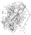
【図1】本実施形態の工作機械の斜視構成図である。
【図2】本実施形態の工作機械の正面図である。
【図3】図2に示す工作機械の正面図の他の状態の説明図である。
【図4】本実施形態の工作機械の側面図である。
【符号の説明】
10…工作機械 12…ベース
14…スライドテーブル 16…スピンドルユニット
18、20…支持アーム 22、24…移動手段
42、44…第1アーム 50、52…第2アーム
62、64…ボールねじ 74、76…リング部材
A…移動範囲 T…工具
W…ワーク[0001]
BACKGROUND OF THE INVENTION
The present invention relates to a machine tool for machining a workpiece by freely moving a spindle unit holding a tool.
[0002]
[Prior art]
Conventionally, an NC machine tool is used in which a spindle unit holding a tool is moved and positioned at a predetermined position with respect to a workpiece to be machined, and then the tool is driven to perform desired machining. ing. In this NC machine tool, the spindle unit is normally supported by a plurality of slide tables, and the slide table is moved in three orthogonal directions so that the tool held by the spindle unit is positioned at a predetermined position of the workpiece. Like to do.
[0003]
[Problems to be solved by the invention]
In this case, since the plurality of slide tables are considerably heavy, not only is the load on the driving means for moving the spindle unit to a predetermined position large, but various techniques are required to maintain the positioning accuracy. .
[0004]
The present invention has been made to solve the above-described problems, and it is an object of the present invention to provide a machine tool that can reduce the weight of a mechanism for moving a spindle unit and can perform tool positioning easily, quickly, and with high accuracy. And
[0005]
[Means for Solving the Problems]
In order to solve the above-described problems, the present invention provides a slide table that can freely advance and retreat with respect to a workpiece to be processed,
One end is pivotally supported by the slide table, the other end is pivotable on a plane perpendicular to the advancing / retreating direction of the slide table,and one end is pivotally supported by the other end of the first arm. A first support arm and a second support arm, the other end of which is configured by a second arm movable in the plane ,
Has a tool that performs a predetermined processing with respect to the frontKiwa overclick, wherein the other end of the second arm is connected, forward and backward in the slide table by the first support arm and the second support arm A spindle unitsupported against the direction ;
A pair of ring members mounted on the spindle unit and independently rotatable about the axis of the spindle unit;
One end side is rotatably supportedby the movable forward and backward state against the slidetable, theother end portion is connected tothe ring member,along with supporting the spindle unit in a plane perpendicular to the moving direction of the slidetable,First moving means and second moving meansfor moving thespindle unit in the plane ;
It is characterized by providing.
[0006]
In this case, the spindle unit moves together with the support arm under the action of the moving means, and the tool mounted on the spindle unit is positioned at a predetermined position of the workpiece. Next, the slide table is moved with respect to the workpiece, and desired processing is performed in a state where the spindle unit is supported by the support arm.
[0007]
DETAILED DESCRIPTION OF THE INVENTION
1 to 4 show a configuration of a
[0008]
The
[0009]
The
[0010]
The
[0011]
[0012]
Next, the operation of the
[0013]
First, the tool T is positioned on the XY plane with respect to the workpiece W. That is, the
[0014]
Here, the
[0015]
Next, the workpiece W is processed by moving the tool T in the arrow Z direction. That is, when the
[0016]
In this case, the position of the tool T in the XY direction with respect to the workpiece W is set by the moving
[0017]
【The invention's effect】
As described above, in the present invention, since the support arm that supports the spindle unit is lightweight, the spindle unit can be set to a predetermined position very easily and quickly. In addition, the spindle unit is reliably supported by a support arm that is configured separately from the moving means for moving the spindle unit, so that the machining can be performed with high accuracy.
[Brief description of the drawings]
FIG. 1 is a perspective configuration diagram of a machine tool according to an embodiment.
FIG. 2 is a front view of the machine tool of the present embodiment.
FIG. 3 is an explanatory view of another state of the front view of the machine tool shown in FIG. 2;
FIG. 4 is a side view of the machine tool of the present embodiment.
[Explanation of symbols]
DESCRIPTION OF
Claims (1)
Translated fromJapanese一端部が前記スライドテーブルに軸支され、他端部が前記スライドテーブルの進退方向と直交する面内で移動可能な第1アームと、一端部が前記第1アームの前記他端部に軸支され、他端部が前記面内で移動可能な第2アームとにより構成される第1支持アームおよび第2支持アームと、
前記ワークに対して所定の加工を行う工具を有し、前記各第2アームの前記各他端部が連結され、前記第1支持アームおよび前記第2支持アームによって前記スライドテーブルの進退方向に対して支持されるスピンドルユニットと、
前記スピンドルユニットに装着され、前記スピンドルユニットの軸線を中心として独立に回転可能な一対のリング部材と、
一端部側が前記スライドテーブルに対して進退自在な状態で軸支され、他端部が前記各リング部材に連結され、前記スライドテーブルの進退方向と直交する面内で前記スピンドルユニットを支持するとともに、前記スピンドルユニットを前記面内で移動させる第1移動手段および第2移動手段と、
を備えることを特徴とする工作機械。A slide table that can move forward and backward with respect to the workpiece to be machined,
One end is pivotally supported by the slide table, the other end is pivotable on a plane perpendicular to the advancing / retreating direction of the slide table,and one end is pivotally supported by the other end of the first arm. A first support arm and a second support arm, the other end of which is configured by a second arm movable in the plane ,
Has a tool that performs a predetermined processing with respect to the frontKiwa overclick, wherein the other end of the second arm is connected, forward and backward in the slide table by the first support arm and the second support arm A spindle unitsupported against the direction ;
A pair of ring members mounted on the spindle unit and independently rotatable about the axis of the spindle unit;
One end side is rotatably supportedby the movable forward and backward state against the slidetable, theother end portion is connected tothe ring member,along with supporting the spindle unit in a plane perpendicular to the moving direction of the slidetable,First moving means and second moving meansfor moving thespindle unit in the plane ;
A machine tool comprising:
Priority Applications (3)
| Application Number | Priority Date | Filing Date | Title |
|---|---|---|---|
| JP32878195AJP3626265B2 (en) | 1995-12-18 | 1995-12-18 | Machine Tools |
| US08/763,783US5807044A (en) | 1995-12-18 | 1996-12-11 | Machine tool with pivoting spindle unit |
| GB9625826AGB2308322B (en) | 1995-12-18 | 1996-12-12 | Machine tool |
Applications Claiming Priority (1)
| Application Number | Priority Date | Filing Date | Title |
|---|---|---|---|
| JP32878195AJP3626265B2 (en) | 1995-12-18 | 1995-12-18 | Machine Tools |
Publications (2)
| Publication Number | Publication Date |
|---|---|
| JPH09168933A JPH09168933A (en) | 1997-06-30 |
| JP3626265B2true JP3626265B2 (en) | 2005-03-02 |
Family
ID=18214061
Family Applications (1)
| Application Number | Title | Priority Date | Filing Date |
|---|---|---|---|
| JP32878195AExpired - Fee RelatedJP3626265B2 (en) | 1995-12-18 | 1995-12-18 | Machine Tools |
Country Status (3)
| Country | Link |
|---|---|
| US (1) | US5807044A (en) |
| JP (1) | JP3626265B2 (en) |
| GB (1) | GB2308322B (en) |
Families Citing this family (30)
| Publication number | Priority date | Publication date | Assignee | Title |
|---|---|---|---|---|
| EP0874715B1 (en)* | 1996-01-03 | 2002-03-13 | Uwe Heisel | Device for numerically controlled machining, manipulating or measuring apparatus |
| US5903125A (en)* | 1997-02-06 | 1999-05-11 | Speedline Technologies, Inc. | Positioning system |
| US5886494A (en)* | 1997-02-06 | 1999-03-23 | Camelot Systems, Inc. | Positioning system |
| DE19743149A1 (en)* | 1997-09-30 | 1999-04-08 | Chiron Werke Gmbh | Machine tool |
| DE19806085B4 (en)* | 1997-10-20 | 2004-11-11 | Cross Hüller GmbH | Machine tool for 3-axis machining of workpieces |
| ATE216939T1 (en)* | 1997-10-20 | 2002-05-15 | Hueller Hille Gmbh | MACHINE TOOL FOR 3-AXIS PROCESSING OF WORKPIECES |
| US6007631A (en) | 1997-11-10 | 1999-12-28 | Speedline Technologies, Inc. | Multiple head dispensing system and method |
| US6206964B1 (en) | 1997-11-10 | 2001-03-27 | Speedline Technologies, Inc. | Multiple head dispensing system and method |
| JP3506205B2 (en)* | 1997-12-03 | 2004-03-15 | 有限会社トミー商会 | Machine Tools |
| US6214117B1 (en) | 1998-03-02 | 2001-04-10 | Speedline Technologies, Inc. | Dispensing system and method |
| FR2779080B1 (en)* | 1998-05-27 | 2000-08-11 | Renault Automation | DEVICE FOR IMPLEMENTING A LOGICAL STRUCTURE OF A MACHINE TOOL WITH PARALLEL ARCHITECTURE AND MACHINE TOOL HAVING SUCH A DEVICE |
| DE19859662C2 (en)* | 1998-12-23 | 2003-06-12 | Chiron Werke Gmbh | Machine tool with tool spindle working from below |
| ES2179706B1 (en)* | 1999-02-11 | 2003-12-16 | Fundacion Fatronik | MODULE WITH PARALLEL KINEMATIC MOVEMENT OF ORTOGONAL AXLES. |
| ATE265290T1 (en)* | 1999-02-12 | 2004-05-15 | Index Werke Kg Hahn & Tessky | MACHINE TOOL |
| SE9901484D0 (en)* | 1999-04-26 | 1999-04-26 | Lidkoeping Machine Tools Ab | Abrasive machine |
| US6402444B1 (en)* | 1999-04-29 | 2002-06-11 | Tsinghua University | Type of parallel machine tool frame driven by slider and extensible strut |
| DE19952530A1 (en)* | 1999-10-30 | 2001-05-10 | Hueller Hille Gmbh | Processing machine for multi-axis movement of a tool or a workpiece |
| DE19963342A1 (en)* | 1999-12-27 | 2001-06-28 | Grob Gmbh & Co Kg | Machine tool |
| DE10045176B4 (en)* | 2000-09-13 | 2004-03-18 | Deckel Maho Pfronten Gmbh | machine tool |
| GB0026234D0 (en)* | 2000-10-26 | 2000-12-13 | Shin Nippon Koki Company Ltd | A spindle head |
| DE10206414A1 (en) | 2001-03-16 | 2002-10-02 | Siemens Ag | Arrangement for positioning tool in defined working area has bearer structure joined to guide carriages via linkage axes and with coupling elements joined by third parallel linkage axis |
| CZ299124B6 (en)* | 2001-06-18 | 2008-04-30 | Kovosvit Mas A.S. | Parallel positioning mechanism, particularly for metal cutting and/or handling and/or measuring |
| US6688458B2 (en) | 2001-10-09 | 2004-02-10 | Speedline Technologies, Inc. | System and method for controlling a conveyor system configuration to accommodate different size substrates |
| DE10258322B3 (en)* | 2002-12-13 | 2004-04-01 | Aesculap Ag & Co. Kg | Guiding unit for a surgical instrument comprises a guiding element for guiding a processing tool and connected to a frame of the guiding unit via connecting rods using a hinge |
| US8082642B1 (en)* | 2008-01-07 | 2011-12-27 | Paradyne Technologies Inc | Articulating head with linear movement assembly for computer controlled milling machines |
| WO2014185880A2 (en)* | 2013-05-13 | 2014-11-20 | Coşkunöz Metal Form Maki̇na Endüstri̇ Ve Ti̇c. A.Ş. | A laser processing machine with a movement mechanism |
| JP6242205B2 (en)* | 2013-12-18 | 2017-12-06 | コマツNtc株式会社 | Machine Tools |
| JP6242204B2 (en)* | 2013-12-18 | 2017-12-06 | コマツNtc株式会社 | Machine Tools |
| US10058939B1 (en)* | 2016-04-25 | 2018-08-28 | MPM Leasing Group, LLC | Adapter to convert a 3-axis milling machine to a 5-axis milling machine |
| CN114131097B (en)* | 2021-11-03 | 2022-11-18 | 广东中包机械有限公司 | Double-cutter moving device |
Family Cites Families (13)
| Publication number | Priority date | Publication date | Assignee | Title |
|---|---|---|---|---|
| US3000270A (en)* | 1955-03-18 | 1961-09-19 | Gorton George Machine Co | Profile milling machines |
| US3806691A (en)* | 1972-11-20 | 1974-04-23 | Cammann Mfg Co | Tool positioner |
| US3864816A (en)* | 1974-04-01 | 1975-02-11 | Paul C Brusch | Cylindrical stock machining apparatus |
| US4002102A (en)* | 1975-11-20 | 1977-01-11 | Aluminum Company Of America | Automatic setup for machining device |
| CH633740A5 (en)* | 1980-01-25 | 1982-12-31 | Charmilles Sa Ateliers | MACHINE TOOL COMPRISING A MOBILE TABLE. |
| FR2510144A1 (en)* | 1981-07-23 | 1983-01-28 | Pechiney Aluminium | METHOD AND APPARATUS FOR SEPARATING ELECTROLYSIS BATH RESIDUES ON PREVIOUS ANODES |
| US4787138A (en)* | 1984-09-04 | 1988-11-29 | Mts Systems Corporation | Method and apparatus for contact insertion |
| US4776749A (en)* | 1986-03-25 | 1988-10-11 | Northrop Corporation | Robotic device |
| DE3710688C2 (en)* | 1987-03-31 | 1994-07-14 | Siemens Ag | Robotic tool |
| US5267818A (en)* | 1991-08-05 | 1993-12-07 | Optima Industries, Inc. | Arrangement for providing planar movement of a machine tool |
| US5401128A (en)* | 1991-08-26 | 1995-03-28 | Ingersoll Milling Machine Company | Octahedral machine with a hexapodal triangular servostrut section |
| US5569004A (en)* | 1993-06-22 | 1996-10-29 | Optima Industries, Inc. | Machine tool positioning arrangement |
| US5388935A (en)* | 1993-08-03 | 1995-02-14 | Giddings & Lewis, Inc. | Six axis machine tool |
- 1995
- 1995-12-18JPJP32878195Apatent/JP3626265B2/ennot_activeExpired - Fee Related
- 1996
- 1996-12-11USUS08/763,783patent/US5807044A/ennot_activeExpired - Fee Related
- 1996-12-12GBGB9625826Apatent/GB2308322B/ennot_activeExpired - Fee Related
Also Published As
| Publication number | Publication date |
|---|---|
| GB2308322B (en) | 1998-02-11 |
| JPH09168933A (en) | 1997-06-30 |
| GB9625826D0 (en) | 1997-01-29 |
| US5807044A (en) | 1998-09-15 |
| GB2308322A (en) | 1997-06-25 |
Similar Documents
| Publication | Publication Date | Title |
|---|---|---|
| JP3626265B2 (en) | Machine Tools | |
| JP2002144176A (en) | Machine tool | |
| WO2008013313A1 (en) | Automatic lathe having a plurality of tool rests | |
| US20210008630A1 (en) | Machine tool | |
| JP2000515075A (en) | 3-axis lathe that performs polar coordinate motion | |
| JPH1034461A (en) | Composite working machine | |
| EP0446253A1 (en) | An arrangement for bringing the tool-carrying end of a robot beam to a desired one of a plurality of possible, predetermined positions | |
| CN216801919U (en) | Numerical control forming machine for end face of aviation conduit | |
| JP3451596B2 (en) | Machine Tools | |
| JP2772906B2 (en) | Automatic lathe | |
| JP4384915B2 (en) | Multi-axis machining center with workpiece holding spindle | |
| JP4216958B2 (en) | Work clamp device | |
| JP3078661U (en) | CNC type lathe characterized by twice the moving speed in the spindle shaft | |
| JP2003089024A (en) | Airframe structure of cantilever type Cartesian machine | |
| US5097877A (en) | Machine tool with automatic tool-changing device | |
| JP2772364B2 (en) | Tool gripper device for industrial robots, etc. | |
| CN216462919U (en) | High-precision automatic screw machine | |
| JPS6186104A (en) | Automatic lathe | |
| JP2574961B2 (en) | Combined machine tool | |
| JP3599155B2 (en) | Work machine | |
| JPH10315005A (en) | Nc automatic lathe | |
| JP2000308901A (en) | Lathe | |
| WO2002102543B1 (en) | Parallel positioning mechanism, especially for machining and/or manipulation and/or measuring | |
| JPH05345245A (en) | Machine tool | |
| JPH09300150A (en) | Work machine |
Legal Events
| Date | Code | Title | Description |
|---|---|---|---|
| A131 | Notification of reasons for refusal | Free format text:JAPANESE INTERMEDIATE CODE: A131 Effective date:20040210 | |
| A521 | Written amendment | Free format text:JAPANESE INTERMEDIATE CODE: A523 Effective date:20040409 | |
| A131 | Notification of reasons for refusal | Free format text:JAPANESE INTERMEDIATE CODE: A131 Effective date:20040831 | |
| A521 | Written amendment | Free format text:JAPANESE INTERMEDIATE CODE: A523 Effective date:20041026 | |
| TRDD | Decision of grant or rejection written | ||
| A01 | Written decision to grant a patent or to grant a registration (utility model) | Free format text:JAPANESE INTERMEDIATE CODE: A01 Effective date:20041124 | |
| A61 | First payment of annual fees (during grant procedure) | Free format text:JAPANESE INTERMEDIATE CODE: A61 Effective date:20041202 | |
| R150 | Certificate of patent or registration of utility model | Free format text:JAPANESE INTERMEDIATE CODE: R150 | |
| FPAY | Renewal fee payment (event date is renewal date of database) | Free format text:PAYMENT UNTIL: 20071210 Year of fee payment:3 | |
| FPAY | Renewal fee payment (event date is renewal date of database) | Free format text:PAYMENT UNTIL: 20081210 Year of fee payment:4 | |
| FPAY | Renewal fee payment (event date is renewal date of database) | Free format text:PAYMENT UNTIL: 20081210 Year of fee payment:4 | |
| FPAY | Renewal fee payment (event date is renewal date of database) | Free format text:PAYMENT UNTIL: 20091210 Year of fee payment:5 | |
| LAPS | Cancellation because of no payment of annual fees |