JP3624986B2 - Beam processing method and apparatus - Google Patents
Beam processing method and apparatusDownload PDFInfo
- Publication number
- JP3624986B2 JP3624986B2JP05405896AJP5405896AJP3624986B2JP 3624986 B2JP3624986 B2JP 3624986B2JP 05405896 AJP05405896 AJP 05405896AJP 5405896 AJP5405896 AJP 5405896AJP 3624986 B2JP3624986 B2JP 3624986B2
- Authority
- JP
- Japan
- Prior art keywords
- electrodes
- ions
- voltage
- processing method
- beam processing
- Prior art date
- Legal status (The legal status is an assumption and is not a legal conclusion. Google has not performed a legal analysis and makes no representation as to the accuracy of the status listed.)
- Expired - Fee Related
Links
- 238000003672processing methodMethods0.000titleclaimsdescription17
- 150000002500ionsChemical class0.000claimsdescription38
- 239000002245particleSubstances0.000claimsdescription28
- 230000007246mechanismEffects0.000claimsdescription15
- 230000007935neutral effectEffects0.000claimsdescription9
- 230000001678irradiating effectEffects0.000claimsdescription5
- 238000009616inductively coupled plasmaMethods0.000claimsdescription4
- 238000005086pumpingMethods0.000claims1
- 239000007789gasSubstances0.000description35
- 238000011144upstream manufacturingMethods0.000description20
- XKRFYHLGVUSROY-UHFFFAOYSA-NArgonChemical group[Ar]XKRFYHLGVUSROY-UHFFFAOYSA-N0.000description16
- 238000010884ion-beam techniqueMethods0.000description14
- 229910052786argonInorganic materials0.000description10
- -1argon ionsChemical class0.000description9
- 238000000034methodMethods0.000description8
- 230000000694effectsEffects0.000description6
- 230000008569processEffects0.000description6
- 230000001133accelerationEffects0.000description5
- 238000010586diagramMethods0.000description5
- 239000012212insulatorSubstances0.000description4
- 239000000460chlorineSubstances0.000description3
- 229910052801chlorineInorganic materials0.000description3
- 238000009792diffusion processMethods0.000description3
- KZBUYRJDOAKODT-UHFFFAOYSA-NChlorineChemical compoundClClKZBUYRJDOAKODT-UHFFFAOYSA-N0.000description2
- 229910001218Gallium arsenideInorganic materials0.000description2
- 230000002411adverseEffects0.000description2
- 238000010891electric arcMethods0.000description2
- 230000005684electric fieldEffects0.000description2
- 238000005530etchingMethods0.000description2
- 239000011521glassSubstances0.000description2
- 238000005459micromachiningMethods0.000description2
- 239000004065semiconductorSubstances0.000description2
- 239000000758substrateSubstances0.000description2
- BSYNRYMUTXBXSQ-UHFFFAOYSA-NAspirinChemical compoundCC(=O)OC1=CC=CC=C1C(O)=OBSYNRYMUTXBXSQ-UHFFFAOYSA-N0.000description1
- ZAMOUSCENKQFHK-UHFFFAOYSA-NChlorine atomChemical compound[Cl]ZAMOUSCENKQFHK-UHFFFAOYSA-N0.000description1
- 239000004642PolyimideSubstances0.000description1
- 229910004298SiO 2Inorganic materials0.000description1
- VYPSYNLAJGMNEJ-UHFFFAOYSA-NSilicium dioxideChemical compoundO=[Si]=OVYPSYNLAJGMNEJ-UHFFFAOYSA-N0.000description1
- 239000000919ceramicSubstances0.000description1
- 238000007796conventional methodMethods0.000description1
- 230000008878couplingEffects0.000description1
- 238000010168coupling processMethods0.000description1
- 238000005859coupling reactionMethods0.000description1
- 230000009849deactivationEffects0.000description1
- 230000007423decreaseEffects0.000description1
- 238000007599dischargingMethods0.000description1
- 238000009826distributionMethods0.000description1
- 238000000605extractionMethods0.000description1
- 230000001939inductive effectEffects0.000description1
- 239000011810insulating materialSubstances0.000description1
- 230000005426magnetic field effectEffects0.000description1
- 238000004519manufacturing processMethods0.000description1
- 239000000463materialSubstances0.000description1
- 229920001721polyimidePolymers0.000description1
- 230000006641stabilisationEffects0.000description1
- 238000011105stabilizationMethods0.000description1
- 230000001629suppressionEffects0.000description1
- 230000007704transitionEffects0.000description1
Images


Landscapes
- Micromachines (AREA)
- Welding Or Cutting Using Electron Beams (AREA)
Description
Translated fromJapanese【0001】
【発明の属する技術分野】
本発明は、低エネルギーから高エネルギーまで、エネルギーレベルの制御が可能で、高密度で指向性の高いエネルギービームを発生させ、そのビームを被加工物に照射する加工方法及び装置に関する。
【0002】
【従来の技術】
従来技術として、従来の高速原子線源について説明する。
常温の大気中で熱運動をしている原子・分子は、おおむね0.05eV前後の運動エネルギーを有している。これに比べてはるかに大きな運動エネルギーで飛翔する原子・分子を、高速原子と呼び、方向性を持ったビーム状に放射される場合に、高速原子線という。
【0003】
従来発表されている、気体原子の高速原子線を発生する高速原子線源のうち、運動エネルギーが0.5eV〜10keVのアルゴン原子を放射する高速原子線源の構造の一例を図4に示す。主な構成は、円筒形陰極1、ドーナッツ状陽極2、高電圧電源3、ガス導入パイプ4、アルゴンガス・プラズマ6、高速原子放出孔7、高速原子線8等である。
【0004】
高速原子線源の電源と放電安定化抵抗(図示しない)以外の構成要素を真空容器に入れ、十分に排気した後、ガス導入パイプ4からアルゴンガスを円筒形陰極1の内部に注入する。ここで直流高電圧電源3によって、陽極2が正電位、陰極1が、負電位となるように、直流電圧を印加する。これで陰極・陽極間に放電が起き、プラズマ6が発生し、アルゴンイオンと電子が生成される。更に、この放電において、円筒形陰極の底面1aから放出する電子は、陽極2に向かって放出され、陽極2の中央の孔を通過して、円筒形陰極の反対側の底面に達し、ここで速度を失って反転し、改めて陽極2に向かって加速され始める。この様に電子は陽極2の中央の孔を介して、円筒形陰極1の両方の底面の間を高周波振動し、そのあいだに、アルゴンガスに衝突して、多数のアルゴンイオンを発生する。
【0005】
こうして発生したアルゴンイオンは、円筒形陰極の底面1aに向かって加速され、十分な運動エネルギーを得るにいたる。この運動エネルギーは、陽極と陰極との間の放電維持電圧が、例えば1kVの時は1keV程度の値となる。円筒形陰極の底面1a近傍の空間は高周波振動をする電子の折り返し点であって、低エネルギーの電子が多数存在する空間である。この空間に入射したアルゴンイオンは電子と衝突・再結合してアルゴン原子に戻る。イオンと電子の衝突において、電子の質量がアルゴンイオンに比べて無視できるほど小さいために、アルゴンイオンの運動エネルギーはほとんど損失せずに、そのまま原子に受け継がれて高速原子となる。従って、この場合の高速原子の運動エネルギーは,1keV程度となる。このアルゴン高速原子は、円筒形陰極の一方の端面に開けられた放出孔から高速原子となって放出されるのである。
【0006】
また、従来の、イオンビーム加工装置の例を、図4に示す。これは、ECRリアクティブイオンビームエッチング装置の概念を示す図である。図から分かるように、通常、プラズマ発生部であるイオン化室11の下流部に、2枚のメッシュ状電極12A,12Bが配置される。その電極間に直流電圧を印加することによって、イオンビームが引き出され、基板ホルダ13に固定された基板14に照射される。図示した例では、マイクロ波と電磁石によるECR放電による高密度プラズマを生成させ、プラズマ中のイオンをビームとして引き出すため、2枚の近接したメッシュ状電極12A,12Bが用いられている。そのイオンビームを試料14に照射してエッチング等の加工を行うのである。
【0007】
【発明が解決しようとする課題】
しかしながら、従来の高速原子線源では、高ビーム密度のプロセスを行う場合では、約1kV以上の高電圧放電を行うことによって、放電電流が高く、高エネルギーの粒子を利用したプロセスに適した高速原子線を形成できるものであった。ところが、例えば、低電圧の放電を行うと、低い放電電流値しか得られず、高ビーム密度を得るためには何らかの方策を行う必要が生じる。これは、マグネットによる磁場を用いた場合でも、同様であり、直流放電の有する特性でもある。従って、放電電流が低いことは、生成されるイオンの生成量が低く、放出される高速原子線量が低いことを意味する。また、従来の高速原子線源では、ビームの散乱が大きく、指向性の悪いビームの放出しかできないため、アスペクト比の高い、微細加工やマイクロマシニングなどで重要となる、3次元的な微小物の任意の場所に、微細加工を行うことは困難であった。
【0008】
又、従来の例えば、ガス放電型プラズマを用いるイオンビーム加工装置は、イオンの失活を押さえるため、メッシュ状の2枚の電極を近接して設置するので、その電極による電界分布が一定でなく、従って、得られるイオンビームの発散角が大変大きい。よって、微細加工に必要な指向性の高いイオンビームを得ることは、従来のイオンビーム加工装置では困難であった。
【0009】
本発明は上述した事情に鑑みて為されたもので、低エネルギーから高エネルギーまでの任意のレベルのエネルギービームを、高密度で且つ良好な指向性で試料に照射することができるエネルギービーム加工方法及び装置を提供することを目的とする。
【0010】
【課題を解決するための手段】
本発明のビーム加工方法は、放電容器と、プラズマ発生機構と、ガス導入機構と、前記放電容器内のプラズマ生成部下流に、孔を有する2枚の平板電極を配置し、該電極間に、直流電圧を印加してイオンの加速を行い、該2枚の電極の内、下流側電極上に被加工物を載置して、該被加工物に該加速されたビームを照射することを特徴とする。
【0011】
又、本発明のビーム加工方法は、放電容器と、誘導結合型プラズマ発生機構と、ガス導入機構と、前記放電容器内のプラズマ生成部下流に、孔を有する2枚の平板電極を配置し、該電極間に、直流電圧を印加してイオンの加速を行い、該2枚の電極の内、下流側電極上に被加工物を載置して、該被加工物に該加速されたビームを照射し、前記誘導結合型プラズマ発生機構は、前記放電容器外部に配置されたコイルと、該コイルに高周波電圧を印加する高周波電源とを備え、誘導結合型高周波放電を用い、前記放電容器内部に高密度プラズマを形成することを特徴とする。又、前記電極に設けられている孔が、複数であることを特徴とする。
【0012】
又、前記上流側電極の厚みが、該電極に設けられている孔径の0.2倍から1倍であり、該孔径がプラズマシース長L以下であることを特徴とする。
【0013】
又、前記上流側電極の厚みが、該電極に設けられている孔径の0.2倍から1倍であり、該孔径がプラズマシース長Lの1倍から3倍であることを特徴とする。
【0014】
又、前記下流側電極の孔径が、上流側電極よりも大きいことを特徴とする。
【0015】
又、前記2枚の電極間に、直流電圧の代わりに、パルス状電圧、または高周波電圧の印加を行うことを特徴とする。
【0016】
又、前記2枚の電極間距離を調整して、ビーム量を制御することを特徴とする。
【0017】
又、前記2枚の電極間を差動排気、又は、側壁にガス粒子排気用の孔を設け、前記プラズマ生成部との圧力差を大きくとることを特徴とする。
【0018】
又、前記2枚の電極の内、下流側の電極が回転、冷却、又は加熱を行いながらビーム照射加工することを特徴とする。
【0019】
又、前記プラズマ発生機構として、誘導結合型高周波放電を用いることを特徴とする。
【0020】
又、前記請求項1乃至請求項9のいずれかに記載のビーム加工方法に用いる加工装置であることを特徴とする。
【0021】
【発明の実施の形態】
本発明のビーム加工装置では、プラズマ発生機構と、放電容器と、ガス導入機構と、2枚の平板型電極とが備えられている。2枚の電極の内、上流側電極には、プラズマによって生成されたイオンが導入される孔が設けられており、下流側電極には、残留ガス粒子を放出する穴が開いている。、その2枚の電極に、直流、又はパルス電圧、又は高周波電圧を印加して、該印加電圧に対応したイオンの加速を行うことができる。加速されたイオンと該イオンの内の残留ガス粒子との電荷交換により、中性化した高速中性粒子とが、下流側電極上に載置された試料に照射されて、該試料の微細加工を行う。
【0022】
このビーム加工装置では、低エネルギーから高エネルギーまで、エネルギーレベルを制御できる高密度のイオンビーム及び中性粒子ビームを2枚の電極間で発生し、かつ、電極構造により高指向性のビームを発生でき、該ビームが下流側電極上に設置された試料を照射して、高速で、高アスペクト比の微細加工を実現できる。
【0023】
このビーム加工装置では、放電容器内に、ガスパイプよりガス粒子が導入され、プラズマ発生機構により、プラズマが発生される。プラズマ発生部の下流部に、2枚の板状電極が設置してあり、上流側電極には、ガス通過孔があり、下流側電極にも、ガス通過孔がある。又、2枚の電極間の側壁にガス粒子排気用、又は、差動排気用の孔を設け、下流側電極のガス通過孔を省略した構造のものもある。いずれの構造でも該上流側電極の孔からプラズマ生成部の中のイオンやプラズマが漏れ出し、該2枚の電極間において、イオンが下流側電極の方向に加速され、下流側電極上に載置されている試料にビームが照射されて、加工が行われる。
【0024】
この時、加速されたイオンの状態で照射されるものと、加速され、電極間で、残留ガス粒子と電荷交換を行い、中性の高速粒子となって、試料を照射するものとがある。このようにプラズマが生成された部分の下流において、2枚の電極に印加された直流電圧にほぼ対応したエネルギーを有するイオン及び高速原子ビームを生成できる。これは、従来の直流放電型高速原子線源と異なり、プラズマ生成部が加速電圧部と独立しているので、低エネルギーでも、高密度プラズマの生成が可能であるからである。そのため、該2枚の電極間に印加する電圧は、低電圧から高電圧まで可能であり、低エネルギーから高エネルギーまで、任意のエネルギーレベルに制御されたビームを発生することができる。
【0025】
本発明のビーム加工方法では、小口径から大口径まで、例えば、ビーム径が10mmから300mm程度までの、エネルギービームの発生が可能である。そのときには、複数の孔を上流側電極に設けて、効率よくイオンの導入を該電極間に行う。プラズマ生成部の下流部に2枚の電極を配した場合では、上流側の電極の孔径と長さの関係によって、2枚の電極間に導入されるイオンの量が変化する。2枚の電極間のイオンの導入を効率よく行うために、孔径をプラズマシース長L以下で、該孔径の0.2倍〜1倍の孔の長さを採用することもある。例えばシースLが3mmで、孔径が1mmの時、約0.2倍〜1倍の孔の長さであると、プラズマ生成部からの極低エネルギーイオンが、電極間に導入され、かつ、両電極間の印加電圧により下流側電極の方に、加速された多量のビームを放射することができる。
【0026】
孔径をプラズマシース長の1倍〜3倍とするのは、上流側電極の孔から、プラズマ自体が、2枚の電極間に漏れ出てきた場合に、大量で効率よくイオンだけを加速するためである。このとき、上流側電極の孔から、漏れ出てきたプラズマは、拡散してガス密度が下がるため、イオンと電子が独自の運動をすることができるようになり、つまり、もはやプラズマ状態ではなくなり、電極間に印加された電界によって、陰極の方向にイオンが加速されるのである。そのため、上流側の電極の孔径が、プラズマの漏れを行うことができるシース長Lの1倍から3倍程度であり、かつ、2枚の電極間で拡散の効果が効く程度のプラズマの漏れでなければならないため、おおよそ、シース長の3倍より大きな孔となると、該効果が小さくなることと、イオンの加速方向に斜め成分の増加がでてくるため、該条件が好ましい。
【0027】
また、孔径がシース長Lの1倍以下の孔径の場合には、多少のプラズマの漏れと極低エネルギーのイオンの導入を2枚の電極間にでき、かつ、該電極間に導入されたイオンが、印加電圧に応じた加速を行い、ビームを発生させ、該ビームを下流側電極上に載置されている試料に照射できるのである。
【0028】
またこのとき、プラズマ下流の2枚の電極間の圧力をプラズマ生成部圧力よりも高真空状態にするため、該2枚の電極間の側壁にガス排気用の孔を設け真空引きするか、又、差動排気を行うようにしてもよい。この様に、例えば、2枚の電極間の圧力状態により、該領域におけるガス粒子の平均自由行程が容器内径より大きい場合など、自由分子流状態を形成できる場合、或いは粘性流から遷移流領域では、約1/4以下の圧力差を実現すると、ガス粒子の効率的な粒子密度の減少を行うことができる。つまり、プラズマ密度の減少を行うことができて、かつ、残留ガス粒子との衝突確率が著しく減少し、従って、イオンが自由に運動できるようになり、電極間の印加電圧に従ったイオンの加速を行って、試料を照射できるのである。このとき、加速されたイオンの内の一部は、残留ガス粒子と電荷交換を行い、中性の高速粒子となって試料に照射される。
【0029】
また、2枚の電極間に導入するイオンの量と圧力差を制御し易くするため、該電極間の距離を調整して、圧力の制御を行うことができる。又、プラズマが過度に漏れた場合のアーク放電が該電極間で起こるなどの悪影響をさけるために、該電極間距離を適正に調整する。この場合には、プラズマ生成部で生成されたプラズマをそのまま、上流側電極の孔より導入し、下流側電極との間で、低電圧グロー放電を行うようにしてもよい。この場合は、低電圧直流放電であっても、高密度プラズマが得られ、従って、高密度高速原子線が得られる。
【0030】
また、該2枚の電極には、直流電圧でなく、パルス状の電圧、又は高周波電圧を与える。これは、アーク放電が起こり易い時には、パルス状の電圧印加を行い高密度のイオンの加速を行い、高密度の高速原子線を放出できる。また、試料が絶縁材料である場合でも、パルス電圧や高周波電圧を利用すると、チャージアップを抑制して、加工を効率よく行うことができる。
【0031】
プラズマ発生機構としては、直流放電、高周波放電、ECR放電、ヘリコン波放電、マイクロ波放電等を用いることができる。これらの中でも、誘導結合型高周波放電方式は、簡便で、かつ、コンパクトであり、高密度プラズマを発生することができるため、本発明のビーム加工方法には特に有効である。また、例えば、大口径で均一性の良いプラズマを発生して、ビーム加工を行うことができる。
【0032】
【実施例】
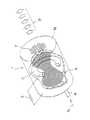
図1は、本発明の第1実施例のビーム加工装置を示す。
セラミックや石英ガラスなどの絶縁物からなる放電管21に、ガス導入パイプ22と、誘導結合型高周波放電用電源24及びコイル25が接続されている。放電管21には1から3ターンほどコイル25が巻いてある。該コイル25に13.56MHzの高周波電圧を印加して、放電管21内にガス26を導入すると高密度プラズマ27が生成される。該プラズマ生成部27の下流領域に、2枚の板状電極29,30が配置されている。該2枚の電極の内、上流側の平板電極29には、ガス及びイオンの通過孔29aがあり、下流側の平板電極30には、該上流側電極孔よりも口径の大きい孔30aが複数開いている。下流側電極30の孔径を大きくすると、下流側電極孔30aのコンダクタンスが上流側電極孔29aより大きくなり、2枚の電極29,30間圧力を、プラズマ生成部圧力よりも低くすることができる。また、放電管内径としては10mm〜300mmが可能である。
【0033】
上流側電極29には、シース長Lと同程度の径の孔29aが開いており、電極厚さは、該シース長の0.2倍から1倍程度である。例えば、放電管内径60mmで、プラズマのシース長が、1mmである時、上流側電極孔径が1mmで複数開いており、該電極の厚さが、0.2mm〜1mm程度である。そして、上流側電極29と下流側電極30の電極間距離は、効率よくビームが生成できるように調整されており、通常、5mm〜100mm程度の距離である。例えば、誘導結合型高周波放電で形成されたプラズマ生成部から該上流側電極の孔29aを通過してきた、多量のイオンは、上記2枚の電極間に印加された直流電圧32(又はパルス電圧、高周波電圧)に従って、加速され、試料34の表面を照射して、微細加工を行うことができる。
【0034】
通常の、直流放電の高速原子線源では、印加電圧が約1kV以上の高電圧でないと、マグネットによる磁場効果を利用しても、高い放電電流が得られない。この実施例のビーム加工装置では、プラズマ生成が、直流印加電圧とは独立にできて、高密度プラズマが生成できるので、2枚の電極に印加する電圧は、低電圧から高電圧まで任意に制御でき、従って、それに対応したエネルギーを有するビームの形成を行うことができる。
【0035】
例えば、誘導結合型高周波放電によるプラズマ生成では、プラズマ密度を1011〜1012/cm3まで、容易に実現できる。そして、電極形状が平板形状であり、平行に配置されているので、指向性が高く、高密度のビームを形成できる。また、孔径も、直進加速性に悪影響を与えない大きさの孔を複数用いる。
【0036】
加工例としては、GaAsやSiなどの半導体材料を塩素ガスを用いて加工する場合、上記のように、塩素ガス26を導入して、プラズマ27を生成し、プラズマ中の塩素イオンもしくはプラズマの導入・拡散が2枚の電極29,30間で行われる。該電極29,30間に低電圧から高電圧までの制御された電圧が印加されているので、該印加電圧に応じて加速された塩素イオンや中性の高速塩素ビーム33を、下流側電極30上に載置したGaAsやSi等の試料34に照射して微細加工を行うことができる。
【0037】
このとき、絶縁物であるガラス、SiO2、ポリイミドなどに微細加工を行う時には、2枚の電極29,30間に印加する電圧が、パルス状電圧、又は高周波電圧を用いると良好な加工特性が得られる場合がある。この様な電圧印加方式により、絶縁物でも、チャージアップによる帯電電圧効果を小さく押さえ、ビーム中のイオンビーム成分を、試料に照射することができる。
【0038】
図2は本発明の第2実施例のビーム加工装置を示す。本実施例も第1実施例とほぼ同様な構成であり、プラズマ生成部27の下流側に2枚の電極29,35を配置してある。また、第1実施例と同様に、放電管21、誘導結合型高周波電源24及びガス導入孔22を備える。この実施例の第1実施例との相違点は、2枚の電極29,35間の絶縁性の側壁に差動排気もしくはガス粒子排気用の孔36を設けてあることである。
【0039】
又、下流側電極35は、回転・昇降・冷却・加熱が可能となっていることである。下流側電極35が、回転・昇降・冷却・加熱が可能となることで、電極間距離や温度などの加工条件や加工均一性を向上させることができる。また、差動排気やガス粒子排気による電極29,35間領域の圧力制御ができるため、特に、プラズマ生成部27よりも低い圧力状態を形成することで、該電極29,35間に導入されたイオンの残留ガス粒子との衝突確率や導入されたプラズマの拡散状態の制御を行うことができる。この様な特徴を利用して、目的のプロセスに用いることができ、例えば、真空状態の違うビーム照射プロセスや、ラジカル量を制御したビーム照射プロセスを行うことができる。そして、低エネルギーで、しかも、高速の微細加工を実現することができる。
【0040】
【発明の効果】
以上に説明したように、本発明を用いると、下記のような優れた効果が期待できる。従来の直流放電型高速原子線源による微細加工では、低加速電圧での放電時に、高密度プラズマが得られず、高密度の低エネルギー高速原子線を発生することが困難であった。また、ビームの指向性が悪く、真空容器内での高速原子線の散乱が大きく、試料に直進性のよいビームを照射することが困難であった。また、従来のイオンビーム加工装置では、2枚の薄いメッシュ電極を、接近して配置するため、指向性の悪いイオンビームの放出しかできなかった。
【0041】
本発明では、この様な問題を解決し、低エネルギーから高エネルギーまでの範囲で、エネルギー制御が可能である高密度のイオンビーム及び高速原子線を発生し、該ビームにより、高速に高精度の微細加工を実現することができる。そのため、2枚の電極間距離、電極孔形状、電極間圧力等の制御が可能であり、これにより被加工物の加工特性に即した様々の微細加工を行うことができる。
この様な特徴を活用した種々の微細加工プロセスに応用でき、例えば、低エネルギーで、低ダメージの半導体やLSIの微細加工、またガラス・絶縁物などの微細加工だけでなく、マイクロセンサやマイクロアクチュエータの作製などに広く応用できる。この様に、本発明の学術的・産業的意義は大変大きく、有意義である。
【図面の簡単な説明】
【図1】本発明の第1実施例のビーム加工装置の説明図。
【図2】本発明の第2実施例のビーム加工装置の説明図。
【図3】従来の高速原子線源の説明図。
【図4】従来のイオンビーム加工装置の説明図。
【符号の説明】
21 放電容器(放電管)
22 ガス導入孔
24 高周波電源
25 コイル
26 ガス
27 プラズマ形成部
29 板状(上流側)電極
30,35 下流側電極
32 直流電源[0001]
BACKGROUND OF THE INVENTION
The present invention relates to a processing method and apparatus for generating an energy beam having a high density and high directivity, capable of controlling an energy level from low energy to high energy, and irradiating the workpiece with the beam.
[0002]
[Prior art]
As a conventional technique, a conventional fast atomic beam source will be described.
Atoms and molecules that are in thermal motion in a normal temperature atmosphere have a kinetic energy of approximately 0.05 eV. Atoms and molecules that fly with much greater kinetic energy than this are called fast atoms, and when emitted in a beam with directionality, they are called fast atom beams.
[0003]
FIG. 4 shows an example of the structure of a fast atomic beam source that emits argon atoms having a kinetic energy of 0.5 eV to 10 keV among conventionally published fast atomic beam sources that generate fast atomic beams of gas atoms. The main components are a cylindrical cathode 1, a donut-shaped anode 2, a high voltage power supply 3, a gas introduction pipe 4, an argon gas / plasma 6, a fast
[0004]
Components other than the power source of the fast atomic beam source and the discharge stabilization resistor (not shown) are put in a vacuum vessel and exhausted sufficiently, and then argon gas is injected into the cylindrical cathode 1 from the gas introduction pipe 4. Here, a direct current voltage is applied by the direct current high voltage power source 3 so that the anode 2 is at a positive potential and the cathode 1 is at a negative potential. As a result, discharge occurs between the cathode and the anode, plasma 6 is generated, and argon ions and electrons are generated. Further, in this discharge, electrons emitted from the bottom surface 1a of the cylindrical cathode are emitted toward the anode 2, pass through the central hole of the anode 2, and reach the bottom surface on the opposite side of the cylindrical cathode, where It loses its speed, reverses, and begins to accelerate toward the anode 2 again. In this way, electrons vibrate at high frequency between the bottom surfaces of the cylindrical cathode 1 through the central hole of the anode 2, and in the meantime, they collide with argon gas to generate a large number of argon ions.
[0005]
Argon ions generated in this way are accelerated toward the bottom surface 1a of the cylindrical cathode to obtain sufficient kinetic energy. This kinetic energy has a value of about 1 keV when the discharge sustaining voltage between the anode and the cathode is, for example, 1 kV. A space in the vicinity of the bottom surface 1a of the cylindrical cathode is a turning point of electrons that vibrate at a high frequency, and is a space in which many low-energy electrons exist. Argon ions incident on this space collide with electrons and recombine to return to argon atoms. In the collision between ions and electrons, the mass of the electrons is negligibly small compared to the argon ions, so that the kinetic energy of the argon ions is hardly lost and is passed on to the atoms as they are to become fast atoms. Therefore, the kinetic energy of fast atoms in this case is about 1 keV. The argon fast atoms are emitted as fast atoms from an emission hole opened in one end face of the cylindrical cathode.
[0006]
An example of a conventional ion beam processing apparatus is shown in FIG. This is a diagram showing the concept of an ECR reactive ion beam etching apparatus. As can be seen from the figure, usually, two
[0007]
[Problems to be solved by the invention]
However, in a conventional fast atom beam source, when a high beam density process is performed, a high voltage discharge of about 1 kV or more is performed, whereby a fast atom suitable for a process using high energy particles with a high discharge current. A line could be formed. However, for example, when a low voltage discharge is performed, only a low discharge current value can be obtained, and some measure must be taken to obtain a high beam density. This is the same even when a magnetic field using a magnet is used, and is a characteristic of DC discharge. Therefore, a low discharge current means that the amount of generated ions is low and the fast atomic dose emitted is low. In addition, the conventional high-speed atomic beam source has a large beam scattering and can only emit a beam with poor directivity. Therefore, a high-aspect ratio three-dimensional minute object that is important in micromachining and micromachining is important. It was difficult to perform microfabrication at an arbitrary place.
[0008]
In addition, in conventional ion beam processing apparatuses using, for example, gas discharge type plasma, two mesh electrodes are placed close to each other in order to suppress ion deactivation, so that the electric field distribution by the electrodes is not constant. Therefore, the divergence angle of the obtained ion beam is very large. Therefore, it has been difficult to obtain an ion beam with high directivity necessary for fine processing with a conventional ion beam processing apparatus.
[0009]
The present invention has been made in view of the circumstances described above, and an energy beam processing method capable of irradiating a sample with an energy beam of any level from low energy to high energy with high density and good directivity. And an apparatus.
[0010]
[Means for Solving the Problems]
In the beam processing method of the present invention, a discharge vessel, a plasma generation mechanism, a gas introduction mechanism, and twoplate electrodeshaving holes are disposed downstream of the plasma generation unit in the discharge vessel, and between the electrodes, A DC voltage is applied to accelerate ions, a workpiece is placed on the downstream electrode of the two electrodes, and the workpiece is irradiated with the accelerated beam. And
[0011]
In the beam processing method of the present invention, a discharge vessel, an inductively coupled plasma generation mechanism, a gas introduction mechanism, and two plate electrodes having holes are disposed downstream of the plasma generation unit in the discharge vessel. A DC voltage is applied between the electrodes to accelerate ions, a workpiece is placed on the downstream electrode of the two electrodes, and the accelerated beam is applied to the workpiece. The inductively coupled plasma generating mechanism is provided with a coil disposed outside the discharge vessel and a high frequency power source for applying a high frequency voltage to the coil. It is characterized by forming a high density plasma. The electrode is provided with a plurality of holes.
[0012]
Further, the thickness of the upstream electrode is 0.2 to 1 times the hole diameter provided in the electrode, and the hole diameter is equal to or less than the plasma sheath length L.
[0013]
Further, the thickness of the upstream electrode is 0.2 to 1 times the hole diameter provided in the electrode, and the hole diameter is 1 to 3 times the plasma sheath length L.
[0014]
The downstream electrode has a hole diameter larger than that of the upstream electrode.
[0015]
Further, a pulse voltage or a high frequency voltage is applied between the two electrodes instead of a DC voltage.
[0016]
The beam amount is controlled by adjusting the distance between the two electrodes.
[0017]
Further, a differential evacuation is provided between the two electrodes or a gas particle evacuation hole is provided in a side wall to increase a pressure difference with the plasma generation unit.
[0018]
Further, the beam irradiation processing is performed while the downstream electrode of the two electrodes rotates, cools, or heats.
[0019]
Further, inductive coupling type high frequency discharge is used as the plasma generation mechanism.
[0020]
Moreover, it is a processing apparatus used for the beam processing method in any one of the said Claim 1 thru | or9 .
[0021]
DETAILED DESCRIPTION OF THE INVENTION
The beam processing apparatus of the present invention includes a plasma generation mechanism, a discharge vessel, a gas introduction mechanism, and two flat plate electrodes. Of the two electrodes, the upstream electrode is provided with a hole into which ions generated by the plasma are introduced, and the downstream electrode is provided with a hole for discharging residual gas particles. By applying a direct current, a pulse voltage, or a high-frequency voltage to the two electrodes, ions corresponding to the applied voltage can be accelerated. The sample placed on the downstream electrode is irradiated with the neutralized high-speed neutral particles by charge exchange between the accelerated ions and the residual gas particles in the ions, and the sample is finely processed. I do.
[0022]
This beam processing device generates a high-density ion beam and neutral particle beam that can control the energy level from low energy to high energy between two electrodes, and generates a highly directional beam by the electrode structure. It is possible to irradiate a sample placed on the downstream electrode with the beam, and to realize fine processing with a high aspect ratio at a high speed.
[0023]
In this beam processing apparatus, gas particles are introduced from a gas pipe into a discharge vessel, and plasma is generated by a plasma generation mechanism. Two plate-like electrodes are installed in the downstream part of the plasma generating part, the upstream electrode has a gas passage hole, and the downstream electrode also has a gas passage hole. There is also a structure in which a hole for gas particle exhaust or differential exhaust is provided in a side wall between two electrodes, and a gas passage hole of a downstream electrode is omitted. In any structure, ions and plasma in the plasma generation part leak from the hole of the upstream electrode, and ions are accelerated in the direction of the downstream electrode between the two electrodes and placed on the downstream electrode. Processing is performed by irradiating the sample being irradiated with a beam.
[0024]
At this time, there are those that are irradiated in the state of accelerated ions, and those that are accelerated and charge-exchanged with the residual gas particles between the electrodes to become neutral high-speed particles and irradiate the sample. Thus, ions and fast atom beams having energy substantially corresponding to the DC voltage applied to the two electrodes can be generated downstream of the portion where the plasma is generated. This is because, unlike the conventional DC discharge type fast atomic beam source, the plasma generation unit is independent of the acceleration voltage unit, so that high-density plasma can be generated even with low energy. Therefore, the voltage applied between the two electrodes can be from a low voltage to a high voltage, and a beam controlled to an arbitrary energy level from a low energy to a high energy can be generated.
[0025]
In the beam processing method of the present invention, it is possible to generate an energy beam from a small diameter to a large diameter, for example, a beam diameter of about 10 mm to 300 mm. At that time, a plurality of holes are provided in the upstream electrode, and ions are efficiently introduced between the electrodes. When two electrodes are arranged downstream of the plasma generation unit, the amount of ions introduced between the two electrodes varies depending on the relationship between the hole diameter and length of the upstream electrode. In order to efficiently introduce ions between the two electrodes, the hole diameter may be less than or equal to the plasma sheath length L and a hole length of 0.2 to 1 times the hole diameter may be employed. For example, when the sheath L is 3 mm and the hole diameter is 1 mm, when the hole length is about 0.2 to 1 times, extremely low energy ions from the plasma generation unit are introduced between the electrodes, and both A large amount of an accelerated beam can be emitted toward the downstream electrode by the applied voltage between the electrodes.
[0026]
The reason why the hole diameter is 1 to 3 times the length of the plasma sheath is that when the plasma itself leaks between the two electrodes from the hole of the upstream electrode, it accelerates only ions in a large amount and efficiently. It is. At this time, the plasma leaked from the hole of the upstream electrode diffuses and the gas density decreases, so that ions and electrons can move independently, that is, no longer in a plasma state, Ions are accelerated in the direction of the cathode by the electric field applied between the electrodes. Therefore, the hole diameter of the upstream electrode is about 1 to 3 times the sheath length L capable of performing plasma leakage, and the plasma leakage is such that the diffusion effect is effective between the two electrodes. Therefore, when the hole is approximately larger than three times the sheath length, the effect is reduced, and an oblique component increases in the ion acceleration direction.
[0027]
Further, when the hole diameter is not more than 1 times the sheath length L, some plasma leakage and introduction of extremely low energy ions can be performed between the two electrodes, and ions introduced between the electrodes can be introduced. However, the acceleration according to the applied voltage is generated to generate a beam, and the beam can be irradiated to the sample placed on the downstream electrode.
[0028]
At this time, in order to make the pressure between the two electrodes downstream of the plasma higher than the plasma generating part pressure, a gas exhaust hole is provided in the side wall between the two electrodes, and vacuuming is performed. Alternatively, differential exhaust may be performed. Thus, for example, when a free molecular flow state can be formed, such as when the mean free path of gas particles in the region is larger than the inner diameter of the vessel due to the pressure state between the two electrodes, or in the transition flow region from the viscous flow When a pressure difference of about 1/4 or less is realized, the gas particle can be efficiently reduced in particle density. In other words, the plasma density can be reduced, and the probability of collision with residual gas particles is significantly reduced, so that ions can move freely and the ions are accelerated according to the applied voltage between the electrodes. And the sample can be irradiated. At this time, some of the accelerated ions exchange charges with residual gas particles, and become neutral high-speed particles, which are irradiated onto the sample.
[0029]
In addition, in order to easily control the amount of ions introduced between the two electrodes and the pressure difference, the distance between the electrodes can be adjusted to control the pressure. In addition, the distance between the electrodes is appropriately adjusted in order to avoid adverse effects such as arc discharge occurring between the electrodes when the plasma leaks excessively. In this case, the plasma generated by the plasma generation unit may be introduced as it is from the hole of the upstream electrode, and low voltage glow discharge may be performed between the plasma and the downstream electrode. In this case, high-density plasma can be obtained even with a low-voltage direct current discharge, and thus a high-density fast atom beam can be obtained.
[0030]
In addition, a pulse voltage or a high frequency voltage is applied to the two electrodes instead of a DC voltage. When arc discharge is likely to occur, a pulsed voltage is applied to accelerate high-density ions, and high-density fast atomic beams can be emitted. Even when the sample is an insulating material, if a pulse voltage or a high-frequency voltage is used, charge-up can be suppressed and processing can be performed efficiently.
[0031]
As the plasma generation mechanism, DC discharge, high frequency discharge, ECR discharge, helicon wave discharge, microwave discharge, or the like can be used. Among these, the inductively coupled high frequency discharge method is particularly effective for the beam processing method of the present invention because it is simple and compact and can generate high-density plasma. In addition, for example, plasma processing with a large diameter and good uniformity can be generated to perform beam processing.
[0032]
【Example】
FIG. 1 shows a beam processing apparatus according to a first embodiment of the present invention.
A
[0033]
The
[0034]
In a normal DC discharge fast atomic beam source, unless the applied voltage is a high voltage of about 1 kV or higher, a high discharge current cannot be obtained even if the magnetic field effect by the magnet is used. In the beam processing apparatus of this embodiment, plasma generation can be performed independently of the DC applied voltage, and high-density plasma can be generated. Therefore, the voltage applied to the two electrodes is arbitrarily controlled from a low voltage to a high voltage. Therefore, a beam having a corresponding energy can be formed.
[0035]
For example, in plasma generation by inductively coupled high-frequency discharge, the plasma density can be easily realized up to 1011 to 1012 / cm3 . And since the electrode shape is a flat plate shape and is arranged in parallel, the directivity is high and a high-density beam can be formed. Also, a plurality of holes having a size that does not adversely affect the linear acceleration performance are used.
[0036]
As a processing example, when a semiconductor material such as GaAs or Si is processed using chlorine gas, as described above,
[0037]
At this time, when fine processing is performed on glass, which is an insulator, SiO2, polyimide, or the like, if the voltage applied between the two
[0038]
FIG. 2 shows a beam processing apparatus according to a second embodiment of the present invention. This embodiment also has substantially the same configuration as that of the first embodiment, and two
[0039]
Further, the
[0040]
【The invention's effect】
As described above, when the present invention is used, the following excellent effects can be expected. In microfabrication using a conventional DC discharge type fast atomic beam source, high-density plasma cannot be obtained during discharge at a low acceleration voltage, and it is difficult to generate a high-density, low-energy fast atomic beam. Further, the directivity of the beam is poor, the scattering of high-speed atomic beams in the vacuum vessel is large, and it is difficult to irradiate the sample with a beam having good straightness. Further, in the conventional ion beam processing apparatus, since two thin mesh electrodes are arranged close to each other, only an ion beam with poor directivity can be emitted.
[0041]
In the present invention, such a problem is solved, and a high-density ion beam and a high-speed atomic beam capable of energy control are generated in a range from a low energy to a high energy. Fine processing can be realized. For this reason, it is possible to control the distance between the two electrodes, the shape of the electrode hole, the pressure between the electrodes, and the like, and various fine processing can be performed in accordance with the processing characteristics of the workpiece.
It can be applied to various microfabrication processes that make use of such features. For example, not only microfabrication of low energy, low damage semiconductors and LSIs, and microfabrication of glass and insulators, but also microsensors and microactuators Can be widely applied to the production of. Thus, the academic and industrial significance of the present invention is very large and meaningful.
[Brief description of the drawings]
FIG. 1 is an explanatory diagram of a beam processing apparatus according to a first embodiment of the present invention.
FIG. 2 is an explanatory diagram of a beam processing apparatus according to a second embodiment of the present invention.
FIG. 3 is an explanatory diagram of a conventional fast atomic beam source.
FIG. 4 is an explanatory diagram of a conventional ion beam processing apparatus.
[Explanation of symbols]
21 Discharge vessel (discharge tube)
22
Claims (10)
Translated fromJapanese該電極間に、直流電圧を印加してイオンの加速を行い、 A DC voltage is applied between the electrodes to accelerate ions,
該2枚の電極の内、下流側電極上に被加工物を載置して、該被加工物に該加速されたビームを照射し、 Place the workpiece on the downstream electrode of the two electrodes, irradiate the workpiece with the accelerated beam,
前記誘導結合型プラズマ発生機構は、前記放電容器外部に配置されたコイルと、該コイルに高周波電圧を印加する高周波電源とを備え、誘導結合型高周波放電を用い、前記放電容器内部に高密度プラズマを形成することを特徴とするビーム加工方法。 The inductively coupled plasma generating mechanism includes a coil disposed outside the discharge vessel and a high frequency power source for applying a high frequency voltage to the coil, and uses inductively coupled high frequency discharge to generate a high density plasma inside the discharge vessel. Forming a beam.
Priority Applications (1)
| Application Number | Priority Date | Filing Date | Title |
|---|---|---|---|
| JP05405896AJP3624986B2 (en) | 1996-02-16 | 1996-02-16 | Beam processing method and apparatus |
Applications Claiming Priority (1)
| Application Number | Priority Date | Filing Date | Title |
|---|---|---|---|
| JP05405896AJP3624986B2 (en) | 1996-02-16 | 1996-02-16 | Beam processing method and apparatus |
Publications (2)
| Publication Number | Publication Date |
|---|---|
| JPH09225653A JPH09225653A (en) | 1997-09-02 |
| JP3624986B2true JP3624986B2 (en) | 2005-03-02 |
Family
ID=12960024
Family Applications (1)
| Application Number | Title | Priority Date | Filing Date |
|---|---|---|---|
| JP05405896AExpired - Fee RelatedJP3624986B2 (en) | 1996-02-16 | 1996-02-16 | Beam processing method and apparatus |
Country Status (1)
| Country | Link |
|---|---|
| JP (1) | JP3624986B2 (en) |
- 1996
- 1996-02-16JPJP05405896Apatent/JP3624986B2/ennot_activeExpired - Fee Related
Also Published As
| Publication number | Publication date |
|---|---|
| JPH09225653A (en) | 1997-09-02 |
Similar Documents
| Publication | Publication Date | Title |
|---|---|---|
| JP3328498B2 (en) | Fast atom beam source | |
| US6435131B1 (en) | Ion flow forming method and apparatus | |
| JP2886978B2 (en) | Electron cyclotron resonance plasma source and operation method | |
| JPH09266096A (en) | Plasma processing apparatus and plasma processing method using the same | |
| JP2006506521A (en) | High deposition rate sputtering | |
| JP2006505906A (en) | Method and apparatus for generating high density plasma | |
| JP2006505128A (en) | Plasma treatment magnetically enhanced by high power pulses | |
| KR100835355B1 (en) | Ion injection device using plasma | |
| JP2000323463A (en) | Plasma processing method | |
| JPH08102279A (en) | Microwave plasma generator | |
| JP2002289581A (en) | Neutral beam processing equipment | |
| JP4073173B2 (en) | Neutral particle beam processing equipment | |
| JP2000317303A (en) | Plasma processing apparatus and plasma processing method using the same | |
| JP3064214B2 (en) | Fast atom beam source | |
| JP3624986B2 (en) | Beam processing method and apparatus | |
| JPS61177728A (en) | Apparatus for irradiation with low-energy ionized particle | |
| JPH076998A (en) | Microwave plasma processing equipment | |
| JP3363040B2 (en) | Fast atom beam source | |
| JP2674995B2 (en) | Substrate processing method and apparatus | |
| JP3423543B2 (en) | Fast atom beam source | |
| JP4384295B2 (en) | Plasma processing equipment | |
| JPH0221296B2 (en) | ||
| JPH09223594A (en) | Beam source and micro-working method | |
| JPS6075589A (en) | Dry etching device | |
| JP2005116312A (en) | Microwave plasma generator |
Legal Events
| Date | Code | Title | Description |
|---|---|---|---|
| A131 | Notification of reasons for refusal | Free format text:JAPANESE INTERMEDIATE CODE: A131 Effective date:20040210 | |
| A521 | Written amendment | Free format text:JAPANESE INTERMEDIATE CODE: A523 Effective date:20040406 | |
| TRDD | Decision of grant or rejection written | ||
| A01 | Written decision to grant a patent or to grant a registration (utility model) | Free format text:JAPANESE INTERMEDIATE CODE: A01 Effective date:20041124 | |
| A61 | First payment of annual fees (during grant procedure) | Free format text:JAPANESE INTERMEDIATE CODE: A61 Effective date:20041124 | |
| R150 | Certificate of patent or registration of utility model | Free format text:JAPANESE INTERMEDIATE CODE: R150 | |
| FPAY | Renewal fee payment (event date is renewal date of database) | Free format text:PAYMENT UNTIL: 20091210 Year of fee payment:5 | |
| FPAY | Renewal fee payment (event date is renewal date of database) | Free format text:PAYMENT UNTIL: 20101210 Year of fee payment:6 | |
| LAPS | Cancellation because of no payment of annual fees |