JP3624871B2 - Stabilizer device - Google Patents
Stabilizer deviceDownload PDFInfo
- Publication number
- JP3624871B2 JP3624871B2JP2001277749AJP2001277749AJP3624871B2JP 3624871 B2JP3624871 B2JP 3624871B2JP 2001277749 AJP2001277749 AJP 2001277749AJP 2001277749 AJP2001277749 AJP 2001277749AJP 3624871 B2JP3624871 B2JP 3624871B2
- Authority
- JP
- Japan
- Prior art keywords
- hydraulic
- vehicle
- stabilizer
- fluid
- hydraulic pressure
- Prior art date
- Legal status (The legal status is an assumption and is not a legal conclusion. Google has not performed a legal analysis and makes no representation as to the accuracy of the status listed.)
- Expired - Fee Related
Links
Images


Landscapes
- Vehicle Body Suspensions (AREA)
Description
Translated fromJapanese【0001】
【発明が属する技術分野】
本発明はスタビライザバーの弾性力を制御可能なスタビライザ装置に関するものである。
【0002】
【従来の技術】
特表平11−510761号公報には、前輪側のスタビライザバーの弾性力を制御する液圧シリンダと、後輪側のスタビライザバーの弾性力を制御する液圧シリンダと、これら2つの液圧シリンダにおいて、ピストンによって仕切られた2つの液圧室の互いに対応する液圧室同士をそれぞれ接続する液通路とを含むスタビライザ装置が記載されている。
【0003】
【発明が解決しようとする課題、課題解決手段および効果】
本発明は、上記公報に記載のスタビライザ装置における液圧シリンダまたは液通路において液漏れが生じた場合のロール抑制効果の低下を抑制することを課題とする。この課題は、スタビライザ装置を下記各態様の構成のものとすることによって解決される。各態様は、請求項と同様に、項に区分し、各項に番号を付し、必要に応じて他の項の番号を引用する形式で記載する。これは、あくまで、本明細書に記載の技術の理解を容易にするためであり、本明細書に記載の技術的特徴およびそれらの組み合わせが以下の各項に限定されると解釈されるべきではない。また、1つの項に複数の事項が記載されている場合、常に、すべての事項を一緒に採用しなければならないものではなく、一部の事項のみを取り出して採用することも可能である。
【0004】
以下の各項のうち、(1)項〜(5)項が請求項1〜5に対応し、(6)項が請求項6に対応する。
【0005】
(1)前輪側に設けられたスタビライザバーの弾性力を制御する液圧シリンダと、
後輪側に設けられたスタビライザバーの弾性力を制御する液圧シリンダと、
これら前輪側の液圧シリンダと後輪側の液圧シリンダとにおいて、ピストンで仕切られた2つの液圧室の機能が同じ液圧室同士を接続する2つの液通路とを含むとともに、これら2つの液圧シリンダが、これら2つの液通路の両方がともに連通状態にある場合において、車両の互いに対角位置にある車輪が同相に、対角位置にない車輪が逆相に上下方向に移動した場合に、前記2つの液通路に作動液が流れ、車両がローリングした場合に、前記2つの液通路に作動液が流れない状態で接続されたスタビライザ装置であって、
前記2つの液通路を共に遮断可能な遮断装置と、
前記2つの液通路の少なくとも一方の液圧に基づいてフェールが検出された場合に限って、前記遮断装置を制御することにより、前記2つの液通路をともに連通状態から遮断状態にする遮断装置制御装置と
を含むことを特徴とするスタビライザ装置。
本項に記載のスタビライザ装置においては、フェールが検出された場合に限って、遮断装置の制御により、2つの液通路が連通状態から遮断状態とされる。遮断装置によって2つの液通路が共に遮断されれば、2つの液圧シリンダを遮断することができる。それにより、例えば、一方の液圧シリンダまたは液通路の一部において液漏れが生じても、その影響が他方の液圧シリンダに及ぶことを防止することができる。前輪側と後輪側とのいずれか一方においては液圧シリンダが正常に作用可能となるため、両方の作用が異常になる場合に比較して、ロール抑制効果の低減を抑制することができる。
2つの液通路のうちの少なくとも一方の液圧に基づけば液漏れが生じているか否かを検出することができる。例えば、液圧が通常あり得ない程度に低い場合、車両の旋回状態等に基づいて決まる液圧に対して低い場合には、液漏れが生じたとすることができる。
遮断装置は、2つの液通路に共通に設けられた1つの遮断弁を含むものであっても、液通路にそれぞれ対応して設けられた2つの遮断弁を含むものであってもよい。
なお、液圧シリンダにおける互いに対応する液圧室は、機能が互いに同じ液圧室である。車両が傾いた時に、液圧が高くなる液圧室同士、低くなる液圧室同士であり、また、ピストンの前方の液圧室同士、ピストンの後方の液圧室同士である。
(2)前記遮断装置制御装置が、前記2つの液通路の少なくとも一方の液圧を検出する液圧検出装置を含む(1)項に記載のスタビライザ装置。
遮断装置は、2つの液通路のうちの高い方に基づいて制御されるようにしたり、液圧差に基づいて制御されるようにしたりすることができる。
【0006】
(3)前記遮断装置制御装置が、(c)前記車両の走行状態を検出する走行状態検出装置と、(d)前記2つの液通路の少なくとも一方の液圧と、前記走行状態検出装置によって検出された走行状態と前記2つの液通路の少なくとも一方の液圧との間の関係とに基づいて前記フェールを検出する手段とを含む(1)項または(2)項に記載のスタビライザ装置。
液圧シリンダにおいて、ピストンに加えられる力と液漏れが生じていない場合の少なくとも一方の液通路の液圧との間には予め定められた関係が成立する。そのため、実際にピストンに加えられる力と、これらの関係とに基づけば、液漏れが生じていない場合の液通路の液圧を推定することができる。それに対して、実際の液圧が、実際にピストンに加えられる力とこれらの関係とに基づいて決まる液圧に対して小さい場合には、液漏れが生じている可能性があると推定することができる。
ピストンに加えられる力を実際に検出することは困難であるが、ピストンに加えられる力は、車両に加えられる遠心力が大きいほど大きいとすることができる。遠心力は、横加速度や、車両の旋回半径および走行速度に基づいて推定することができる。そこで、走行状態検出装置は、横加速度、旋回半径および走行速度等を検出するものとすることが望ましい。旋回半径はステアリングホイールの操舵角度に基づいて推定することができ、走行状態検出装置は、横加速度センサを含むものとしたり、操舵角センサおよび車速センサを含むもの等としたりすることができる。
(4)前記走行状態検出装置が、前記車両に加わる遠心力に関連する遠心力関連量を検出する遠心力関連量検出装置を含む(3)記載のスタビライザ装置。
遠心力関連量には、前述のように、横加速度、操舵角および車速等が該当する。
(5)前記走行状態検出装置が、前記車両の横加速度を検出する横加速度検出装置を含む(3)項または(4)項に記載のスタビライザ装置。
【0007】
(6)前記遮断装置制御装置が、前記前輪側の液圧シリンダ、後輪側の液圧シリンダおよび2つの液通路のうちの少なくとも1つに液漏れが生じたことを前記フェールが生じたとして検出する手段を含む(1)ないし(5)項のいずれか1つに記載のスタビライザ装置。
(7)前記フェールを検出する手段が、前記車両の横加速度を前記遠心力関連量として検出する横加速度検出装置を含む(3)項ないし(6)項のいずれか1つに記載のスタビライザ装置。
(8)前記フェールを検出する手段が、前記2つの液通路の少なくとも一方の液圧を検出する液圧検出装置を含む(3)項ないし(7)項のいずれか1つに記載のスタビライザ装置。
(9)前記フェールを検出する手段によって前記フェールが検出された場合に、前記前輪側の液圧シリンダと後輪側の液圧シリンダとを互いに独立にする装置を含む(3)項ないし(8)項のいずれか1つに記載のスタビライザ装置。
(10)前記液圧シリンダのピストンに設けられたピストンロッドが前記スタビライザバーに係合させられ、前記液圧シリンダの本体が車体側部材に取り付けられた(1)項ないし(9)項のいずれか1つに記載のスタビライザ装置。
(11)前記液圧シリンダにおけるピストンの両側にそれぞれピストンロッドが設けられ、そのピストンロッドの一方に前記スタビライザバーが係合させられた(1)ないし(10)項のいずれか1つに記載のスタビライザ装置。
【0008】
【発明の実施の形態】
本発明の一実施形態であるスタビライザ装置について図面に基づいて詳細に説明する。
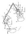
図1において、車両の前輪側と後輪側とにそれぞれスタビライザバー10,12が設けられる。スタビライザバー10,12は、それぞれ、ねじれにより弾性を有する部材であり、概してコの字型を成したものである。スタビライザバー10,12は、中間部の車両の幅方向に延びた中間ロッド部14と、中間ロッド部14と一体的に設けられ、それの両側の車両のほぼ長手方向に延びた左右アーム部16、18とを有する。
【0009】
前輪側において、ロアアーム20は、支持部22において図示しない車体側部材に前輪24を揺動可能に支持する。スタビライザバー10は、左右アーム部16,18(左アーム部16については図示しない)の端部に設けられ、ゴムブッシュまたはボールジョイントを含む連結部19においてロアアーム20の中間部に相対回動可能に支持される。また、中間ロッド部14の右側の部分において液圧シリンダ30を介して車体側部材に支持され、左側の部分において連結ロッド32を介して車体側部材に支持される。
液圧シリンダ30は、図2に示すように、ハウジング36と、それにシール部材37を介して液密かつ摺動可能に嵌合されたピストン38とを含み、ピストン38の一方の側にピストンロッド40が設けられる。ピストンロッド40の端部のボールジョイントまたはゴムブッシュを含む連結部41において中間ロッド部14に軸線回りに回動可能かつ軸線に対して傾き可能に取り付けられ、ハウジング36のピストンロッド40が延びる側とは反対側に設けられた取付部42において車体側部材に相対回動可能かつ傾き可能に取り付けられる。このように、液圧シリンダ30が、車両の上下方向に延びた姿勢で、ピストンロッド40が中間ロッド14に連携させられた状態で設けられる。
連結ロッド32は、一端部の連結部において中間ロッド部14に軸線回りに回転可能かつ軸線に対して傾き可能な状態で取り付けられ、他端部の取付部において車体側部材に相対回動可能かつ傾き可能に取り付けられる。
【0010】
後輪側において、スタビライザバー12は、左右アーム部16,18の端部のボールジョイントまたはゴムブッシュを含む連結部48において、リヤアクスルハウジング50に相対回動可能かつ軸線に対して傾き可能に取り付けられる。リヤアクスルハウジング50は、図示しない駆動源の駆動トルクをデファレンシャル52を介して左右後輪54に伝達する車軸等を保持する。
また、中間ロッド部14の右側部において液圧シリンダ60を介して車体側部材に支持され、左側部において連結ロッド62を介して車体側部材に支持される。液圧シリンダ60は、液圧シリンダ30と同様に、ハウジング66、ハウジング66にシール部材67を介して液密かつ摺動可能に嵌合されたピストン68、ピストンロッド70等を含むものであり、ピストンロッド70の連結部71aにおいてスタビライザバー12に連携させられ、ハウジング66の取付部71bにおいて車体側部材に取り付けられる。液圧シリンダ60は、車両の上下方向に延びた姿勢で設けられる。
【0011】
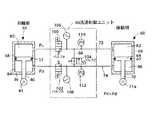
このように、本実施形態においては、前輪側および後輪側のそれぞれにおいて、スタビライザバー10,12の中間ロッド部14の車両の幅方向における同じ側に、それぞれ、液圧シリンダ30,60が上下方向に延びた姿勢で、ピストンロッド40,70がスタビライザバー10,12に連携させられた状態で設けられる。そして、これら液圧シリンダ30,60における互いに対応する液圧室同士が液通路72,74によって接続される。
液通路72によって、液圧シリンダ30、60の、それぞれのピストン38、68のピストンロッド40、70とは反対側の液圧室80、82が接続され、液通路74によって、液圧シリンダ30,60の、それぞれのピストン38,68のピストンロッド側の液圧室84,86が接続される。液圧室80および82、液圧室84および86は、それぞれ、互いに対応する室であり、同じ機能を有する室、すなわち、ローリング時に液圧が高くなる室または低くなる室である。これら液通路72,74は接続通路88によって接続される。以下、液圧室80,82が上側に位置し、液圧室84,86が下側に位置するために、液圧室80,82を上側液圧室と称し、液圧室84,86を下側液圧室と称する。
【0012】
本実施形態においては、液通路72,74および接続通路88における作動液の流通状態を制御する流通制御ユニット90が設けられる。流通制御ユニット90は、複数の電磁開閉弁100,102,104、アキュムレータ106,108等を含む。
液通路72,74に設けられた電磁開閉弁100,102はソレノイドに電流が供給されない場合に開状態にある常開弁であり、接続通路88に設けられた電磁開閉弁104はソレノイドに電流が供給されない場合に閉状態にある常閉弁である。図面においては、電磁開閉弁100をバルブA,電磁開閉弁102をバルブB,電磁開閉弁104をバルブCと略記する。
【0013】
アキュムレータ106,108は、液通路72,74の液圧が過大になった場合に、その作動液を吸収し、液通路72,74の液圧が過小になった場合に作動液を補うために設けられたものである。
流通制御ユニット90には、液圧センサ110,112も含まれる。液圧センサ110は液通路72に設けられ、液圧センサ112は液通路74に設けられる。液圧センサ110,112は、電磁開閉弁100,102,104の図示する状態において、それぞれ、上側液圧室80,82、下側液圧室84,86の液圧を検出し得る。
【0014】
流通制御ユニット90は、コンピュータを主体とする制御部を含む。制御部は、CPU132,ROM134,RAM136,入出力部138等を含む。入出力部138には、上述の液圧センサ110,112、各車輪毎に設けられた車高センサ114、車両の走行状態を検出する車両走行状態取得装置140が接続されている。車両走行状態取得装置140には、車両の横Gを検出する横Gセンサ146,ステアリングホイールの操舵角を検出する操舵角センサ148、車両の走行速度を検出する車速センサ150等が含まれる。操舵角センサ148によって検出された操舵角に基づいて車両の旋回状態が検出される。入出力部138には、駆動回路150を介して電磁開閉弁100,102,104が接続される。また、ROM134には、図4のフローチャートで表されるバルブ制御プログラム、図5のマップで表されるテーブル等が記憶されている。
【0015】
流通制御ユニット90において、各電磁開閉弁100,102,104は原則として図示する原位置にある。車両が直進状態にある場合には、液圧センサ110による検出液圧、液圧センサ112による検出液圧は、ほぼ予め定められた値Pc、Pdにある。ここで、液圧センサ110によって検出される上側液圧室80,82の液圧Pcは、液圧センサ112によって検出される下側液圧室84,86の液圧Pdより低い。ピストン38,68においては、上側液圧室80,82に対向する受圧面積の方が下側液圧室84,86に対向する受圧面積より大きいため、車両の直進状態(ピストン38,68に外力が加えられない状態)において、下側液圧室84,86の液圧の方が高くなるようにされるのである。液圧シリンダ30,60の各々においてピストン38,68に対する互いに逆向きの力が釣り合った状態にされるのであり、スタビライザバー10,12にねじりが生じることがなく、車両の姿勢がほぼ水平に保たれる。
【0016】
車両の右旋回状態においては、遠心力によって車両は旋回外側(左側)が下がる状態に傾く。前輪側および後輪側において、液圧シリンダ30,60の上側の液圧室80,82の液圧が低くなり、下側の液圧室84,86の液圧が高くなる。これら上側の液圧室80,82同士が液通路72によって接続され、下側の液圧室84,86同士が液通路74によって接続されるが、これら液圧室80,82の液圧がほぼ同じで、液圧室84,86の液圧がほぼ同じであるため、これらの間に作動液の流通は殆ど生じない。液圧の変動に応じてアキュムレータ106,108との間に作動液の多少の流出入が生じ、液圧シリンダ30,60においてピストン38,68が移動するが、その移動量は互いにほぼ等しく、かつ、比較的小さいため、スタビライザバー10,12において中間ロッド部14の傾きが抑制されて、ねじりが生じ、弾性力が発生させられる。その弾性力、すなわち、復元力によって左側の車輪と車体との間には両者を離間させる向きの力が、右側の車輪と車体との間には両者を接近させる向きの力がそれぞれ加えられ、車両の傾きが抑制される。
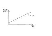
この場合の上側の液圧室80,82の液圧と下側の液圧室84,86の液圧との差は車両を傾かせる力、すなわち、液圧シリンダ30,60のピストン38,68に加えられる力が大きいほど大きくなる。例えば、遠心力が大きいほど液圧差が大きくなるのであり、遠心力と液圧差との関係は予め決まっている。また、上側の液圧室80,82の液圧と下側の液圧室84,86の液圧との間にもほぼ一定の関係が成り立つため、上側の液圧室80,82と下側の液圧室84,86とのいずれか一方の液圧と、遠心力(車両を傾かせる力)との間にもほぼ一定の関係が成立する。したがって、本実施形態においては、遠心力関連量としての横Gと液通路72,74のうちの高い方の液圧との間の関係がテーブル化されて記憶されている。
【0017】
車両の左旋回状態においては、遠心力によって車両は旋回外側である右側が下がるように傾く。液圧シリンダ30,60において、下側の液圧室84,86の液圧が低くなり、上側の液圧室80,82の液圧が高くなる。液通路72,74における作動液の流通が抑制され、液圧シリンダ30,60においてピストン38,68の移動が抑制される。スタビライザバー10,12がねじられて弾性力が発生させられる。
この場合において、液通路72,74の高い方の液圧が横Gに対して決まる液圧より低い場合には、液通路72,74あるいは液圧シリンダ30,60の少なくとも1つにおいて液漏れが生じたと推定することができる。そこで、液漏れが生じたと推定された場合に電磁開閉弁100,102の両方が閉状態に切り換えられる。その結果、液漏れが生じた一方の液圧シリンダあるいは液通路の液漏れが生じた部分から他方の液圧シリンダを遮断することができる。他方の液圧シリンダにおいては、ピストンで仕切られた2つの液圧室の間に液圧差が生じ得る。前輪側と後輪側とのいずれか一方の側において、スタビライザバーに弾性力が発生させられ、車両の傾きが抑制される。前輪側と後輪側との両方の液圧シリンダが作用不能となる場合に比較して、いずれか一方の液圧シリンダが作用可能となれば、車両のロール抑制効果の低下を抑制することができる。
【0018】
また、例えば、車両が凹凸の大きい路面を走行している場合において、右前輪および左後輪が上方に左前輪および右後輪が下方に位置する状態においては、前輪側の液圧シリンダ30の下側液圧室84の液圧が低く、後輪側の液圧シリンダ60の下側液圧室86の液圧が高くなり、液圧シリンダ30の上側液圧室80の液圧が高く、液圧シリンダ60の上側液圧室82が低くなる。液通路72,74における作動液の流通が許容される。スタビライザバー10,12の自由な傾きが許容され、ねじりが生じることはない。
【0019】
さらに、車両の直進状態においては、前述のように、上側液圧室の液圧、下側液圧室の液圧、すなわち、液通路72,74の液圧はそれぞれ予め決まった大きさにあるはずである。
それに対して、車両の旋回状態において液圧シリンダ30,60の液圧室80,84の間、液圧室82,86の間に大きな液圧差が生じた場合あるいはシール不良が生じた場合等には、ピストン38,68のシール部材37,67を経て作動液が、高圧側の液圧室から低圧側の液圧室に向かって漏れることがある。そのため、車両が直進状態に戻った場合に、液通路72,74の液圧がそれぞれ設定値Pc、Pdとは異なる大きさとなる。車両が直進状態にあるにもかかわらず、スタビライザバーに弾性力が発生させられ、それによって、車両が傾くことがある。そこで、本実施形態においては、車両が直進状態にある場合、すなわち、車両がほぼ水平な姿勢にあるはずであると推定された場合において、液通路74の液圧が液通路72の液圧より設定圧以上高い場合に、電磁開閉弁104が開状態に切り換えられて、液通路72,74の液圧が予め定められた設定圧Pc、Pdになるように制御される。
【0020】
ステップ1(以下、S1と略称する。他のステップについても同様とする)において、横Gセンサ146によって検出された検出値が設定値Gsより大きいか否かが判定される。旋回中であるか否かが判定されるのである。設定値Gsは例えば、比較的小さい値とすることができる。設定値Gsは、旋回状態であるか直進状態であるかを検出し得る値であればよい。
実際の横Gが設定値Gsより大きい場合には、S2において電磁開閉弁104が閉状態にされる。そして、S3において、液圧センサ110,112の液圧が検出されて、S4において、これら横Gと高い方の液圧との関係が図5のマップの正常な領域にあるかフェール領域にあるかが判定される。正常な領域にある場合には、S4における判定がNOとなり、S5において、電磁開閉弁100,102が開状態にされ、フェール領域にある場合には、S4における判定がYESとなって、S6において、電磁開閉弁100,102が閉状態にされる。液圧シリンダ30,60が互いに独立とされ、前輪側と後輪側とのいずれか一方の側において、スタビライザバーがねじられて、液漏れが生じてもローリングが抑制される。
【0021】
実際の横Gが設定値Gs以下であり、車両がほぼ直進状態にあると判定された場合には、S1における判定がNOとなり、S7において、電磁開閉弁100,102が開状態にされる。S8において、電磁開閉弁104が開状態にあるか否かが判定される。電磁開閉弁104は通常は閉状態にあるのが普通であるため、たいていの場合には判定がNOとなって、S9において、液通路74の液圧(P2)が液通路72の液圧(P1)より設定値α以上大きいか否かが判定される。大きい場合には、判定がYESとなり、S10において、電磁開閉弁104が開状態に切り換えられる。液圧が高い方の液通路74から低い方の液通路72へ作動液が流れ、これらの液圧差が小さくなる。液通路72,74の液圧が予め定められた設定圧Pc,Pdになるまで、電磁開閉弁104は開状態に保たれる。液通路72,74の液圧が設定圧Pc,Pdに達すると、S11における判定がYESとなって、S12において、電磁開閉弁104が閉状態に切り換えられる。
これによって、液通路72,74の液圧が車両の姿勢がほぼ水平になる大きさとされ、車両が傾くことが防止される。
【0022】
なお、上記実施形態においては、横Gと液圧との関係が記憶されていたが、ステアリングホイールの操舵角θおよび車速Vと液圧との関係が記憶されるようにすることもできる。ステアリングホイールの操舵角θが大きく(旋回半径が小さく)車速が大きいほど遠心力が大きくなり、液圧が高くなる。また、2つの液通路72,74の液圧のうちの高い方の液圧と横Gとの関係を表すテーブルが記憶されていたが、2つの液通路72,74の液圧差と横Gとの関係を表すテーブルが記憶されるようにすることもできる。
さらに、上記実施形態においては、横Gに基づいて車両が旋回状態にあるか直進状態にあるかが判定されるようにされていたが、ステアリングホイールの操舵角や前輪舵角に基づいて判定されるようにすることもできる。
また、液通路72,74の液圧差は各車輪毎に設けられた車高センサ114の検出値に基づいて推定することもできる。例えば、車両が直進状態にあるとされた場合において、車高センサ114による検出値に基づいて求められた液圧差が設定値以上である場合に、電磁開閉弁104が開状態に切り換えられるようにする。このように、車高センサ114の検出値に基づけば、実際の車両の姿勢が水平であるか否かを検出することができるのである。
【0023】
さらに、液圧シリンダ30,60において、ピストンロッド40,70の直径がピストン38,68の直径に対して小さい場合には、車両の姿勢が水平である場合に、ピストン38,68の両側の液圧室の液圧がほぼ同じであると考えることができる。この場合には、車両の直進状態において、常に電磁開閉弁104が開状態に切り換えられるようにすることができる。直進状態にある間中開状態にすることも可能であり、その場合には、電磁開閉弁104を常開弁としてもよい。
【0024】
また、液圧シリンダにおいて、ピストンの両側にピストンロッドが設けられるようにすることができる。例えば、図6において、液圧シリンダ200のハウジング202にピストン204が液密かつ摺動可能に嵌合されるのであるが、ピストン204の両側にそれぞれピストンロッド206,208が設けられている。ピストンロッド206はハウジング202から突出して、スタビライザバーに連結部210において連結させられ、ピストンロッド208は、ハウジング202の内部に設けられた摺動部212において液密に摺動可能とされており、ハウジング202から突出することはない。ハウジング202の取付部214において車体側部材に取り付けられる。
【0025】
さらに、スタビライザバー10,12は前輪側と後輪側とで同じ状態で取り付けられるようにすることができる。また、液圧シリンダは、上下方向でなく、水平方向に延びた姿勢で設けられるようにすることもできる。いずれにしても、スタビライザバー10,12と、それが保持される車体側部材との相対位置関係によって決まるのであり、それぞれ対応する液圧室同士が液通路によって接続されるようにする。さらに、電磁開閉弁100,102,104の代わりに前後の差圧を供給電流に応じた大きさに制御可能な電磁制御弁とすることもできる。
また、上記実施形態においては、3つの電磁開閉弁100,102,104が設けられていたが、これらすべてを設ける必要は必ずしもない。電磁開閉弁100,102が設けられれば、電磁開閉弁104が設けられなくても、液漏れ検出時のロール抑制効果の低下を抑制することができる。電磁開閉弁104が設けられれば電磁開閉弁100,102が設けられなくても、車両の直進状態における運転者の違和感を軽減させることができる。
【0026】
本発明は、前記〔発明が解決しようとする課題、課題解決手段および効果〕に記載の態様の他、当業者の知識に基づいて種々の変更、改良を施した態様で実施することができる。
【図面の簡単な説明】
【図1】本発明の一実施形態であるスタビライザ装置を概念的に示す図である。
【図2】上記スタビライザ装置の液圧系の回路図である。
【図3】上記スタビライザ装置の流通制御ユニットを概念的に示す図である。
【図4】上記流通制御ユニットのROMに格納されたバルブ制御プログラムを表すフローチャートである。
【図5】上記流通制御ユニットのROMに格納されたテーブルを表すマップである。
【図6】上記スタビライザ装置に含まれる液圧シリンダの別の態様を示す図である。
【符号の説明】
10,12スタビライザバー
30,60液圧シリンダ
90流通制御ユニット
100,102,104電磁開閉弁
110,112液圧センサ
140車両走行状態検出装置
146横Gセンサ[0001]
[Technical field to which the invention belongs]
The present invention relates to a stabilizer device capable of controlling the elastic force of a stabilizer bar.
[0002]
[Prior art]
Japanese Patent Application Laid-Open No. 11-510761 discloses a hydraulic cylinder for controlling the elastic force of the stabilizer bar on the front wheel side, a hydraulic cylinder for controlling the elastic force of the stabilizer bar on the rear wheel side, and these two hydraulic cylinders. Describes a stabilizer device including fluid passages respectively connecting two fluid pressure chambers of two fluid pressure chambers partitioned by a piston.
[0003]
[Problems to be Solved by the Invention, Means for Solving Problems, and Effects]
This invention makes it a subject to suppress the fall of the roll suppression effect when the liquid leak arises in the hydraulic cylinder in the stabilizer apparatus as described in the said gazette, or a liquid channel | path. This problem is solved by making the stabilizer device have the configuration of each aspect described below. As with the claims, each aspect is divided into sections, each section is numbered, and is described in a form that cites the numbers of other sections as necessary. This is merely for the purpose of facilitating understanding of the technology described in this specification, and the technical features described in this specification and combinations thereof should not be interpreted as being limited to the following items. Absent. In addition, when a plurality of items are described in one section, it is not always necessary to employ all items together, and it is also possible to take out only some items and employ them.
[0004]
Of the following items, (1) to (5) correspond to claims 1 to 5,(6)Claim is claim 6Corresponding to
[0005]
(1) a hydraulic cylinder that controls the elastic force of a stabilizer bar provided on the front wheel side;
A hydraulic cylinder for controlling the elastic force of the stabilizer bar provided on the rear wheel side;
In these front wheel side hydraulic cylinder and rear wheel side hydraulic cylinder, two hydraulic chambers partitioned by pistonsSame functionIncluding two fluid passages connecting the fluid pressure chambersAt the same time, when both of these two hydraulic cylinders are in communication with each other, the wheels in the diagonal position of the vehicle are in the same phase and the wheels not in the diagonal position are in the opposite phase. A stabilizer device connected to the two liquid passages when the hydraulic fluid flows to the two liquid passages when the vehicle moves and the hydraulic fluid does not flow to the two liquid passages;
A blocking device capable of blocking both the two liquid passages;
A shut-off device control for controlling both of the two liquid passages from the communication state to the shut-off state by controlling the shut-off device only when a failure is detected based on the fluid pressure of at least one of the two liquid passages. Equipment and
The stabilizer apparatus characterized by including.
In the stabilizer device described in this section,Only when a failure is detected, the two liquid passages are changed from the communication state to the cutoff state by the control of the cutoff device.If the two liquid passages are blocked by the blocking device, the two hydraulic cylinders can be blocked. Thereby, for example, even if liquid leakage occurs in one hydraulic cylinder or a part of the liquid passage, the influence can be prevented from reaching the other hydraulic cylinder. Since the hydraulic cylinder can operate normally on either the front wheel side or the rear wheel side, it is possible to suppress the reduction of the roll suppression effect as compared with the case where both operations become abnormal.
Based on the hydraulic pressure of at least one of the two liquid passages, it is possible to detect whether or not liquid leakage has occurred. For example, when the hydraulic pressure is so low that it is not possible, or when the hydraulic pressure is low relative to the hydraulic pressure determined based on the turning state of the vehicle, etc., it can be assumed that liquid leakage has occurred.
The shut-off device may include one shut-off valve provided in common to the two liquid passages, or may include two shut-off valves provided respectively corresponding to the liquid passages.
Note that the corresponding hydraulic chambers in the hydraulic cylinder are hydraulic chambers having the same function. When the vehicle tilts, the hydraulic chambers increase in hydraulic pressure, the hydraulic chambers decrease in hydraulic pressure, the hydraulic chambers in front of the piston, and the hydraulic chambers behind the piston.
(2) The hydraulic pressure detection device in which the shut-off device control device detects the hydraulic pressure of at least one of the two liquid passages.TheThe stabilizer device according to item (1).
The shut-off device can be controlled based on the higher one of the two liquid passages, or can be controlled based on the hydraulic pressure difference.
[0006]
(3) The shut-off device control device is (c) a travel state detection device that detects the travel state of the vehicle, and (d)Hydraulic pressure of at least one of the two liquid passages;Based on the running state detected by the running state detection device and the relationship between the hydraulic pressure of at least one of the two liquid passages.Means for detecting the failureThe stabilizer device according to (1) or (2).
In the hydraulic cylinder, a predetermined relationship is established between the force applied to the piston and the hydraulic pressure in at least one of the liquid passages when no liquid leakage occurs. Therefore, based on the force actually applied to the piston and these relations, it is possible to estimate the liquid pressure in the liquid passage when no liquid leakage occurs. On the other hand, if the actual hydraulic pressure is smaller than the hydraulic pressure determined based on the force actually applied to the piston and these relations, it is assumed that there is a possibility of liquid leakage. Can do.
Although it is difficult to actually detect the force applied to the piston, the force applied to the piston can be increased as the centrifugal force applied to the vehicle increases. The centrifugal force can be estimated based on the lateral acceleration, the turning radius of the vehicle, and the traveling speed. Therefore, it is desirable that the traveling state detection device detects lateral acceleration, turning radius, traveling speed, and the like. The turning radius can be estimated based on the steering angle of the steering wheel, and the traveling state detection device can include a lateral acceleration sensor, a steering angle sensor, a vehicle speed sensor, or the like.
(4) The stabilizer device according to (3), wherein the traveling state detection device includes a centrifugal force related amount detection device that detects a centrifugal force related amount related to a centrifugal force applied to the vehicle.
As described above, the lateral force, the steering angle, the vehicle speed, and the like correspond to the centrifugal force related amount.
(5) The stabilizer device according to (3) or (4), wherein the running state detection device includes a lateral acceleration detection device that detects a lateral acceleration of the vehicle.
[0007]
(6)The shut-off device control device has confirmed that a liquid leak has occurred in at least one of the hydraulic cylinder on the front wheel side, the hydraulic cylinder on the rear wheel side, and two fluid passages.As the failure occurredIncluding means to detect(1)Or(Five)The stabilizer apparatus as described in any one of claim | items.
(7)The means for detecting the failure includes a lateral acceleration detection device that detects lateral acceleration of the vehicle as the centrifugal force related amount.(3)Term or(6)Any one of the termsThe stabilizer apparatus as described in.
(8)The means for detecting the failure includes a hydraulic pressure detecting device for detecting a hydraulic pressure of at least one of the two liquid passages.(3)Term or(7)TermThe stabilizer apparatus as described in any one of these.
(9And a device for making the front wheel side hydraulic cylinder and the rear wheel side hydraulic cylinder independent of each other when the failure is detected by the fail detecting means.(3)Term or(8)The stabilizer apparatus as described in any one of claim | items.
(10(1) to (1), wherein a piston rod provided on a piston of the hydraulic cylinder is engaged with the stabilizer bar, and a body of the hydraulic cylinder is attached to a vehicle body side member.9The stabilizer device as described in any one of the items).
(11) Piston rods are provided on both sides of the piston in the hydraulic cylinder, and the stabilizer bar is engaged with one of the piston rods (1) to (TenThe stabilizer device as described in any one of the items).
[0008]
DETAILED DESCRIPTION OF THE INVENTION
A stabilizer device according to an embodiment of the present invention will be described in detail with reference to the drawings.
In FIG. 1,
[0009]
On the front wheel side, the
As shown in FIG. 2, the
The connecting
[0010]
On the rear wheel side, the
Further, the
[0011]
Thus, in the present embodiment, the
The
[0012]
In the present embodiment, a
The electromagnetic on / off
[0013]
The
The
[0014]
The
[0015]
In the
[0016]
In the right turn state of the vehicle, the vehicle is tilted so that the outer side of the turn (left side) is lowered by centrifugal force. On the front wheel side and the rear wheel side, the hydraulic pressure in the upper
In this case, the difference between the hydraulic pressure in the upper
[0017]
In the left turn state of the vehicle, the vehicle is tilted so that the right side, which is the outside of the turn, is lowered by centrifugal force. In the
In this case, when the higher fluid pressure in the
[0018]
Further, for example, when the vehicle is traveling on a rough road surface, when the right front wheel and the left rear wheel are located above and the left front wheel and the right rear wheel are located below, the
[0019]
Further, in the straight traveling state of the vehicle, as described above, the fluid pressure in the upper fluid pressure chamber and the fluid pressure in the lower fluid pressure chamber, that is, the fluid pressure in the
On the other hand, when a large hydraulic pressure difference occurs between the
[0020]
In step 1 (hereinafter abbreviated as S1. The same applies to other steps), it is determined whether or not the detected value detected by the
When the actual lateral G is larger than the set value Gs, the electromagnetic on-off
[0021]
If it is determined that the actual lateral G is equal to or less than the set value Gs and the vehicle is substantially in a straight traveling state, the determination in S1 is NO, and in S7, the electromagnetic on-off
As a result, the hydraulic pressure in the
[0022]
In the above embodiment, the relationship between the lateral G and the hydraulic pressure is stored, but the relationship between the steering angle θ of the steering wheel and the vehicle speed V and the hydraulic pressure may be stored. As the steering angle θ of the steering wheel is larger (the turning radius is smaller) and the vehicle speed is larger, the centrifugal force becomes larger and the hydraulic pressure becomes higher. Further, a table representing the relationship between the higher hydraulic pressure of the two
Further, in the above embodiment, it is determined based on the lateral G whether the vehicle is in a turning state or a straight traveling state, but is determined based on the steering angle of the steering wheel or the front wheel steering angle. You can also make it.
Further, the hydraulic pressure difference between the
[0023]
Further, in the
[0024]
In the hydraulic cylinder, piston rods can be provided on both sides of the piston. For example, in FIG. 6, the
[0025]
Furthermore, the stabilizer bars 10 and 12 can be attached in the same state on the front wheel side and the rear wheel side. Further, the hydraulic cylinder can be provided in a posture extending in the horizontal direction instead of the vertical direction. In any case, it is determined by the relative positional relationship between the stabilizer bars 10 and 12 and the vehicle body side member on which the stabilizer bars 10 and 12 are held, and the corresponding hydraulic pressure chambers are connected by the liquid passages. Furthermore, instead of the electromagnetic on-off
Moreover, in the said embodiment, although the three electromagnetic opening-and-closing valves 100,102,104 were provided, it is not necessarily required to provide all these. If the electromagnetic on-off
[0026]
The present invention can be practiced in various modifications and improvements based on the knowledge of those skilled in the art, in addition to the aspects described in [Problems to be Solved by the Invention, Problem Solving Means and Effects].
[Brief description of the drawings]
FIG. 1 is a diagram conceptually showing a stabilizer device according to an embodiment of the present invention.
FIG. 2 is a circuit diagram of a hydraulic system of the stabilizer device.
FIG. 3 is a diagram conceptually showing a distribution control unit of the stabilizer device.
FIG. 4 is a flowchart showing a valve control program stored in a ROM of the distribution control unit.
FIG. 5 is a map showing a table stored in the ROM of the distribution control unit.
FIG. 6 is a view showing another aspect of a hydraulic cylinder included in the stabilizer device.
[Explanation of symbols]
10,12 Stabilizer bar
30, 60 hydraulic cylinder
90 distribution control unit
100, 102, 104 solenoid on-off valve
110, 112 hydraulic pressure sensor
140 Vehicle Running State Detection Device
146 horizontal G sensor
Claims (6)
Translated fromJapanese後輪側に設けられたスタビライザバーの弾性力を制御する液圧シリンダと、
これら前輪側の液圧シリンダと後輪側の液圧シリンダとにおいて、ピストンで仕切られた2つの液圧室の機能が同じ液圧室同士を接続する2つの液通路とを含むとともに、これら2つの液圧シリンダが、これら2つの液通路の両方がともに連通状態にある場合において、車両の互いに対角位置にある車輪が同相に、対角位置にない車輪が逆相に上下方向に移動した場合に、前記2つの液通路に作動液が流れ、車両がローリングした場合に、前記2つの液通路に作動液が流れない状態で接続されたスタビライザ装置であって、
前記2つの液通路を共に遮断可能な遮断装置と、
前記2つの液通路の少なくとも一方の液圧に基づいてフェールが検出された場合に限って、前記遮断装置を制御することにより、前記2つの液通路をともに連通状態から遮断状態にする遮断装置制御装置と
を含むことを特徴とするスタビライザ装置。A hydraulic cylinder that controls the elastic force of the stabilizer bar provided on the front wheel side;
A hydraulic cylinder for controlling the elastic force of the stabilizer bar provided on the rear wheel side;
In the these front side of the hydraulic cylinder and the rear wheel side of the hydraulic cylinder,with and a two liquidpassages functions of the two hydraulic chambers partitioned by the pistonis connected to thesame hydraulic pressure chamber with eachother, these two When one of the two hydraulic passages is in communication with each other, the wheels in the diagonal position of the vehicle moved in the same phase and the wheels not in the diagonal position moved up and down in the opposite phase. In this case, when the hydraulic fluid flows through the two fluid passages and the vehicle rolls, the stabilizer device is connected in a state where the hydraulic fluid does not flow through the two fluid passages,
A blocking device capable of blocking both the two liquid passages;
A shut-off device control for controlling both of the two liquid passages from the communication state to the shut-off state by controlling the shut-off device only when a failure is detected based on the fluid pressure of at least one of the two liquid passages. stabilizer device characterized by comprising adevice as <br/>.
Priority Applications (1)
| Application Number | Priority Date | Filing Date | Title |
|---|---|---|---|
| JP2001277749AJP3624871B2 (en) | 2001-09-13 | 2001-09-13 | Stabilizer device |
Applications Claiming Priority (1)
| Application Number | Priority Date | Filing Date | Title |
|---|---|---|---|
| JP2001277749AJP3624871B2 (en) | 2001-09-13 | 2001-09-13 | Stabilizer device |
Publications (2)
| Publication Number | Publication Date |
|---|---|
| JP2003080916A JP2003080916A (en) | 2003-03-19 |
| JP3624871B2true JP3624871B2 (en) | 2005-03-02 |
Family
ID=19102225
Family Applications (1)
| Application Number | Title | Priority Date | Filing Date |
|---|---|---|---|
| JP2001277749AExpired - Fee RelatedJP3624871B2 (en) | 2001-09-13 | 2001-09-13 | Stabilizer device |
Country Status (1)
| Country | Link |
|---|---|
| JP (1) | JP3624871B2 (en) |
Families Citing this family (3)
| Publication number | Priority date | Publication date | Assignee | Title |
|---|---|---|---|---|
| JP3675459B2 (en) | 2003-07-30 | 2005-07-27 | アイシン精機株式会社 | Stabilizer control device |
| RU2591836C1 (en) | 2012-09-20 | 2016-07-20 | Хитачи Отомотив Системз, Лтд. | Suspension device |
| CN107953736B (en)* | 2016-10-14 | 2024-02-27 | 宇通客车股份有限公司 | Vehicle and interconnection type air damper module and air damper for suspension thereof |
- 2001
- 2001-09-13JPJP2001277749Apatent/JP3624871B2/ennot_activeExpired - Fee Related
Also Published As
| Publication number | Publication date |
|---|---|
| JP2003080916A (en) | 2003-03-19 |
Similar Documents
| Publication | Publication Date | Title |
|---|---|---|
| JP3901190B2 (en) | Vehicle suspension system | |
| JP3951728B2 (en) | Stabilizer device | |
| US7963547B2 (en) | Articulated vehicle stabilization system | |
| US10384739B2 (en) | Control system of the trim of vehicles with more than two wheels | |
| US7770909B2 (en) | Articulated vehicle stabilization system | |
| US12083848B1 (en) | Single axle roll control system with dual impeller pump arrangement | |
| JP4155066B2 (en) | Vehicle suspension system | |
| US12083851B1 (en) | Single axle roll control system with multiple circuit-specific pressurizing devices | |
| JP2005059613A (en) | Vehicle suspension system | |
| JP3624871B2 (en) | Stabilizer device | |
| JP2003080917A (en) | Stabilizer device | |
| JP2004114876A (en) | Vehicle control device | |
| JP4120539B2 (en) | Suspension system | |
| JPS6296126A (en) | Car height adjustment device | |
| JP4898326B2 (en) | Roll control device | |
| US12251978B2 (en) | Single axle roll control system that includes a dual chamber ball-screw mechanism | |
| JP2005125834A (en) | Stabilizer device | |
| JPS63162314A (en) | Roll stiffness control device for vehicle | |
| JP2004359181A (en) | Vehicle suspension device | |
| JP2008013099A (en) | Roll control device | |
| JPH0399924A (en) | Suspension of vehicle | |
| JPS6320211A (en) | Stabilizer device | |
| JP2004217030A (en) | Lock cylinder control device and stabilizer function control device | |
| JPH04237615A (en) | Control type suspension for vehicle |
Legal Events
| Date | Code | Title | Description |
|---|---|---|---|
| A977 | Report on retrieval | Free format text:JAPANESE INTERMEDIATE CODE: A971007 Effective date:20040414 | |
| A131 | Notification of reasons for refusal | Free format text:JAPANESE INTERMEDIATE CODE: A131 Effective date:20040420 | |
| A521 | Written amendment | Free format text:JAPANESE INTERMEDIATE CODE: A523 Effective date:20040621 | |
| TRDD | Decision of grant or rejection written | ||
| A01 | Written decision to grant a patent or to grant a registration (utility model) | Free format text:JAPANESE INTERMEDIATE CODE: A01 Effective date:20041109 | |
| A61 | First payment of annual fees (during grant procedure) | Free format text:JAPANESE INTERMEDIATE CODE: A61 Effective date:20041122 | |
| R150 | Certificate of patent or registration of utility model | Free format text:JAPANESE INTERMEDIATE CODE: R150 | |
| FPAY | Renewal fee payment (event date is renewal date of database) | Free format text:PAYMENT UNTIL: 20081210 Year of fee payment:4 | |
| FPAY | Renewal fee payment (event date is renewal date of database) | Free format text:PAYMENT UNTIL: 20081210 Year of fee payment:4 | |
| FPAY | Renewal fee payment (event date is renewal date of database) | Free format text:PAYMENT UNTIL: 20091210 Year of fee payment:5 | |
| FPAY | Renewal fee payment (event date is renewal date of database) | Free format text:PAYMENT UNTIL: 20101210 Year of fee payment:6 | |
| FPAY | Renewal fee payment (event date is renewal date of database) | Free format text:PAYMENT UNTIL: 20101210 Year of fee payment:6 | |
| FPAY | Renewal fee payment (event date is renewal date of database) | Free format text:PAYMENT UNTIL: 20111210 Year of fee payment:7 | |
| FPAY | Renewal fee payment (event date is renewal date of database) | Free format text:PAYMENT UNTIL: 20111210 Year of fee payment:7 | |
| FPAY | Renewal fee payment (event date is renewal date of database) | Free format text:PAYMENT UNTIL: 20121210 Year of fee payment:8 | |
| FPAY | Renewal fee payment (event date is renewal date of database) | Free format text:PAYMENT UNTIL: 20131210 Year of fee payment:9 | |
| LAPS | Cancellation because of no payment of annual fees |