JP3623967B2 - Portable multimedia communication terminal device - Google Patents
Portable multimedia communication terminal deviceDownload PDFInfo
- Publication number
- JP3623967B2 JP3623967B2JP52675396AJP52675396AJP3623967B2JP 3623967 B2JP3623967 B2JP 3623967B2JP 52675396 AJP52675396 AJP 52675396AJP 52675396 AJP52675396 AJP 52675396AJP 3623967 B2JP3623967 B2JP 3623967B2
- Authority
- JP
- Japan
- Prior art keywords
- information
- image
- input
- communication path
- control unit
- Prior art date
- Legal status (The legal status is an assumption and is not a legal conclusion. Google has not performed a legal analysis and makes no representation as to the accuracy of the status listed.)
- Expired - Fee Related
Links
- 230000006854communicationEffects0.000titleclaimsdescription180
- 238000004891communicationMethods0.000titleclaimsdescription180
- 238000012545processingMethods0.000claimsdescription26
- 230000007423decreaseEffects0.000claimsdescription16
- 230000003044adaptive effectEffects0.000claimsdescription9
- 239000013598vectorSubstances0.000claimsdescription8
- 230000004044responseEffects0.000claimsdescription4
- 238000000034methodMethods0.000description35
- 230000005540biological transmissionEffects0.000description14
- 230000008569processEffects0.000description9
- 230000008859changeEffects0.000description5
- 238000010586diagramMethods0.000description5
- 230000006870functionEffects0.000description5
- 230000006835compressionEffects0.000description4
- 238000007906compressionMethods0.000description4
- 238000011161developmentMethods0.000description4
- 238000004364calculation methodMethods0.000description3
- 238000005516engineering processMethods0.000description3
- 101000969688Homo sapiens Macrophage-expressed gene 1 proteinProteins0.000description2
- 102100021285Macrophage-expressed gene 1 proteinHuman genes0.000description2
- 230000015572biosynthetic processEffects0.000description2
- 230000000694effectsEffects0.000description2
- 230000009467reductionEffects0.000description2
- 238000000926separation methodMethods0.000description2
- 230000005236sound signalEffects0.000description2
- 238000003786synthesis reactionMethods0.000description2
- 230000007175bidirectional communicationEffects0.000description1
- 230000003111delayed effectEffects0.000description1
- 238000013461designMethods0.000description1
- 238000001514detection methodMethods0.000description1
- 230000006866deteriorationEffects0.000description1
- 238000011982device technologyMethods0.000description1
- 239000004973liquid crystal related substanceSubstances0.000description1
- 238000012806monitoring deviceMethods0.000description1
- 238000012544monitoring processMethods0.000description1
- 230000010355oscillationEffects0.000description1
- 230000002265preventionEffects0.000description1
- 238000003908quality control methodMethods0.000description1
- 238000004904shorteningMethods0.000description1
- 230000002194synthesizing effectEffects0.000description1
Images


Classifications
- H—ELECTRICITY
- H04—ELECTRIC COMMUNICATION TECHNIQUE
- H04N—PICTORIAL COMMUNICATION, e.g. TELEVISION
- H04N7/00—Television systems
- H04N7/24—Systems for the transmission of television signals using pulse code modulation
- H04N7/52—Systems for transmission of a pulse code modulated video signal with one or more other pulse code modulated signals, e.g. an audio signal or a synchronizing signal
- H04N7/54—Systems for transmission of a pulse code modulated video signal with one or more other pulse code modulated signals, e.g. an audio signal or a synchronizing signal the signals being synchronous
- H04N7/56—Synchronising systems therefor
- H—ELECTRICITY
- H04—ELECTRIC COMMUNICATION TECHNIQUE
- H04N—PICTORIAL COMMUNICATION, e.g. TELEVISION
- H04N19/00—Methods or arrangements for coding, decoding, compressing or decompressing digital video signals
- H04N19/10—Methods or arrangements for coding, decoding, compressing or decompressing digital video signals using adaptive coding
- H04N19/134—Methods or arrangements for coding, decoding, compressing or decompressing digital video signals using adaptive coding characterised by the element, parameter or criterion affecting or controlling the adaptive coding
- H04N19/162—User input
- H—ELECTRICITY
- H04—ELECTRIC COMMUNICATION TECHNIQUE
- H04N—PICTORIAL COMMUNICATION, e.g. TELEVISION
- H04N19/00—Methods or arrangements for coding, decoding, compressing or decompressing digital video signals
- H04N19/10—Methods or arrangements for coding, decoding, compressing or decompressing digital video signals using adaptive coding
- H04N19/134—Methods or arrangements for coding, decoding, compressing or decompressing digital video signals using adaptive coding characterised by the element, parameter or criterion affecting or controlling the adaptive coding
- H04N19/164—Feedback from the receiver or from the transmission channel
- H—ELECTRICITY
- H04—ELECTRIC COMMUNICATION TECHNIQUE
- H04N—PICTORIAL COMMUNICATION, e.g. TELEVISION
- H04N19/00—Methods or arrangements for coding, decoding, compressing or decompressing digital video signals
- H04N19/10—Methods or arrangements for coding, decoding, compressing or decompressing digital video signals using adaptive coding
- H04N19/169—Methods or arrangements for coding, decoding, compressing or decompressing digital video signals using adaptive coding characterised by the coding unit, i.e. the structural portion or semantic portion of the video signal being the object or the subject of the adaptive coding
- H04N19/17—Methods or arrangements for coding, decoding, compressing or decompressing digital video signals using adaptive coding characterised by the coding unit, i.e. the structural portion or semantic portion of the video signal being the object or the subject of the adaptive coding the unit being an image region, e.g. an object
- H04N19/176—Methods or arrangements for coding, decoding, compressing or decompressing digital video signals using adaptive coding characterised by the coding unit, i.e. the structural portion or semantic portion of the video signal being the object or the subject of the adaptive coding the unit being an image region, e.g. an object the region being a block, e.g. a macroblock
- H—ELECTRICITY
- H04—ELECTRIC COMMUNICATION TECHNIQUE
- H04N—PICTORIAL COMMUNICATION, e.g. TELEVISION
- H04N19/00—Methods or arrangements for coding, decoding, compressing or decompressing digital video signals
- H04N19/60—Methods or arrangements for coding, decoding, compressing or decompressing digital video signals using transform coding
- H04N19/61—Methods or arrangements for coding, decoding, compressing or decompressing digital video signals using transform coding in combination with predictive coding
- H—ELECTRICITY
- H04—ELECTRIC COMMUNICATION TECHNIQUE
- H04N—PICTORIAL COMMUNICATION, e.g. TELEVISION
- H04N7/00—Television systems
- H04N7/14—Systems for two-way working
- H04N7/141—Systems for two-way working between two video terminals, e.g. videophone
- H04N7/142—Constructional details of the terminal equipment, e.g. arrangements of the camera and the display
- H—ELECTRICITY
- H04—ELECTRIC COMMUNICATION TECHNIQUE
- H04N—PICTORIAL COMMUNICATION, e.g. TELEVISION
- H04N19/00—Methods or arrangements for coding, decoding, compressing or decompressing digital video signals
- H04N19/10—Methods or arrangements for coding, decoding, compressing or decompressing digital video signals using adaptive coding
- H04N19/102—Methods or arrangements for coding, decoding, compressing or decompressing digital video signals using adaptive coding characterised by the element, parameter or selection affected or controlled by the adaptive coding
- H04N19/103—Selection of coding mode or of prediction mode
- H04N19/107—Selection of coding mode or of prediction mode between spatial and temporal predictive coding, e.g. picture refresh
- H—ELECTRICITY
- H04—ELECTRIC COMMUNICATION TECHNIQUE
- H04N—PICTORIAL COMMUNICATION, e.g. TELEVISION
- H04N7/00—Television systems
- H04N7/14—Systems for two-way working
- H04N7/141—Systems for two-way working between two video terminals, e.g. videophone
- H04N7/142—Constructional details of the terminal equipment, e.g. arrangements of the camera and the display
- H04N2007/145—Handheld terminals
Landscapes
- Engineering & Computer Science (AREA)
- Multimedia (AREA)
- Signal Processing (AREA)
- Compression Or Coding Systems Of Tv Signals (AREA)
Description
Translated fromJapanese技術分野
本発明は、消費電力の異なる複数の符号化モードを有するマルチメディア通信端末装置に関するものである。なお、本発明では符号化モードの変化とは、端末において同じ入力情報源(例えば、カメラに入力される画像、マイクに入力される音声等)が与えられた場合でも、伝送される符号化ビットストリームが変化するような端末の状態の変化のことを指す。また、本発明では音声等の単独の情報の通信を行う端末もマルチメディア通信端末に含まれるものとする。
背景技術
ディジタル画像通信を行うことができるマルチメディア通信端末の普及が本格化しつつある。ディジタル画像通信の実用化をもたらした主な要因としては、電子デバイス技術の発展の他に画像情報圧縮技術(画像符号化技術)の進歩を挙げることができる。画像符号化技術とは、音声の1000倍の情報量を持つと言われる画像情報を、伝送・蓄積が可能なレベルまで情報圧縮する技術である。画像符号化技術を用いたディジタル画像通信を行う場合には、送信側の端末は入力画像情報を符号化(圧縮)して符号化ビットストリームに変換して伝送し、受信側の端末は受信したビットストリームを復号化することにより復号化画像を得る。このとき、通信を正しく行うためには通信路の両端に位置する端末が共通の画像符号化方式を採用する必要がある。このため、現在国際標準としてH.261、MPEG1、MPEG2などの標準画像符号化方式が定められている。今後無線画像通信等の新たなアプリケーションに対してさらに多くの標準符号化方式が定められることが予想される。
既に製品化されている画像通信端末はアナログ電話回線、ISDN回線等に接続される有線画像通信端末が中心となっている。しかし、将来は無線回線においても同様の機能が提供できる無線画像通信端末も普及することが予想されている。無線通信端末の特徴はその携帯性にあるため、通常は電力源として蓄電池が使用される。しかし、携帯用端末で使用される計量の蓄電池1個で供給できる電力量には限界があり、連続通信時間を長くするためには端末の消費電力を抑える必要がある。また、監視システムなどでは多数の端末が使用されるため、蓄電池を使用しない場合でも消費電力を抑えることが重要となる。このように省電力化はアプリケーションによっては重要な条件となるが、一方で情報圧縮率の高い画像符号化アルゴリズムは演算量が多く、消費電力も大きくなる傾向がある。一般的にこれまでは画像符号化と言えば情報圧縮率を高めることが第一の目的とされ、消費電力は大きな問題とされていなかった。しかし、マルチメディア通信端末が広く普及し、様々な用途に利用されるようになるであろう将来においては、これまで見過ごされていた消費電力の問題も装置の設計・開発において重要な位置を占めるようになることが予想される。
既に実用化されている携帯装置における省電力化の対策としては、ノート型(ラップトップ)コンピュータにおいていくつかの工夫が見られる。例えば、米国Apple社のMacintosh PowerBook180cでの主な節電機能を以下に示す。
(a)電池残量が一定量より少なくなると液晶ディスプレイのバックライトが自動的に暗くなる。
(b)電池残量がある一定レベル以下になると、ディスプレイに警告メッセージを表示する。
(c)電源を入れたまま一定時間放置しておくと自動的にスリープモード(RAMの記憶内容の保持以外の機能をすべて停止した状態)に入る。
(d)利用者がCPUのクロック周波数を切り換えられるようになっており、処理スピードを落とすことにより電力を節約することが可能となっている。
(e)一定時間CPUへの処理要求が無い場合には、自動的にCPUのクロック周波数を下げる。ラップトップコンピュータにおけるこのような消費電力対策は、画面が見にくくなったり、処理速度が低下することを引き起こす。しかし、一般的には処理内容そのものや、提供される情報そのもの(例えば画面に表示される情報自体)は変化しないのが特徴である。
一般的に情報圧縮率の高い符号化アルゴリズムは複雑な処理を行うために、処理量(演算量)が多くなる傾向がある。演算量が多くなることは消費電力を大きくする原因となり、例えば電力源を蓄電池とするマルチメディア通信端末、又は、消費電力を少なくしなければならない通信端末においては連続通信時間を短くする結果につながってしまう。
そこで、本発明の目的は、消費電力を節約し、必要な連続通話時間を確保することのできる通信端末を提供することにある。特に符号化モードを変更して消費電力の減少を図る通信端末を提供することを目的とする。
発明の開示
上記の目的を達成するために、本発明の通信端末では、異なる複数の符号化モードの画像情報又は音声情報のうち、システム又は外部から要求されたモードに符号化モードを切り換えることにより、消費電力を制御する。
具体的な本発明の通信端末装置は、入力された画像又は音声情報を符号化して通信路へ出力し、上記伝送路から得られる画像又は音声情報を復号化する通信端末装置において、画像又は音声等の入力情報を入力する入力手段(101,102,106,107)と、上記入力情報を通信路に出力し、かつ上記通信路から情報を入力する通信路制御部(123,124)と、上記通信路から得た情報を画像又は音声等により出力する出力手段(103,104,108,109,105)と、上記入力手段及び上記出力手段と上記通信路制御部との間に設けられ、実行時には消費電力の異なる複数の符号化モードのいずれかの符号化モードに従って上記入力情報を符号化し上記通信路から入力された情報を復号化するコーデック手段と(110)、上記符号化モードの選択を制御する制御部(133)とから構成される。
より、通信端末装置の消費電力を少なくするために、例えば、伝送される情報の品質を制御する。品質の制御については自動で切り換える手段または手動え切り換える手段を備える。通信を行なっている最中であれ、通信相手が符号化モードの切り換え操作を行うことも可能である。電力源として用いられる蓄電池の電池残量を監視し、符号化モードごとにそのモードを使用した場合の連続通話可能時間の目安を符号化モード切り換えの実行者に提示する手段とを備え、タイミング良く符号化モードを切り換えることも有効である。また、検出された電池残量が減少するに従って消費電力の少ない符号化モードを選択する手段を具備する。また、符号化モードの切り換えによって不必要となった回路に提供するクロック信号を停止する手段を具備することも有効である。クロック信号に関しては、稼動中の符号化モードの処理量が少ないほど符号化回路に提供するクロック信号の周波数を低くする制御を行う手段を具備することも有効である。画像伝送の際に解像度を制御する手段を具備して消費電力の少ない解像度に制御することも有効である。
動画像符号化を例にすれば、符号化モードは、固定フレーム内符号化とフレーム間/フレーム内適応符号化のモードとを備え、固定フレーム内符号化モードの選択を行なう、もしくは、フレーム間/フレーム内適応符号化のモードの中でも、フレーム内適応符号化の頻度を増やすことにより、消費電力を少なくする制御に有効である。
フレーム間符号化を行なう際にはブロックマッチングに基づく動き補償を実行する手段とを具備し、ブロックマッチングにおけるブロックごとの探索動きベクトル数を少なくする。又は、動画像符号化に関して伝送される画像のフレームレートを制御する手段とを具備し、フレームレートを低くすることも消費電力を少なくするのに有効である。
画像と音声との両方の通信を行うことが可能な場合には、音声のみによる通信を優先的に行なうことにより節電や、突然のデータの消失を防ぐことができる。
カラーの画像情報の送受信が可能な通信端末装置で、白黒画像情報の送受信を行なうことも消費電力を少なくするのに有効である。
符号化モードの切り換え要求を受けた際には、コーデック手段では、符号化モードの切り換え要求の、直後のフレーム分割点、又は、スライス分割点、又は、ブロックマッチングのためのブロックの分割点、で符号化モードを切り換えればよい。
電池残量が少なくなったときに消費電力を少なくする制御を行えば、利用者への警告となると同時に、残りの通話時間を長くすることができる。また、電池残量と希望する通話時間から最適な符号化方式を選択することにより、通話時間が希望より短くならない範囲で最も画質の高い符号化方式を使用することができる。
【図面の簡単な説明】
第1図は、マルチメディア通信端末の構成例を示した図、第2図は、H.261の画像符号化器の構成例を示した図、第3図は、H.261の画像復号化器の構成例を示した図、第4図は、ソフトウェア画像符号化器の構成例を示した図、第5図は、ソフトウェア画像復号化器の構成例を示した図、第6図は、端末利用者が符号化モードを切り換えるマルチメディア通信端末の構成例を示した図、第7図は、符号化モードを自動的に切り換えるマルチメディア通信端末の構成例を示した図、第8図は、通信相手が符号化モードを切り換えるマルチメディア通信端末の構成例を示した図、第9図は、電池残量に応じて符号化モードが変化する様子の例を示した図、第10図は、フレームノートを変化させたときの画像符号化の動作状態を示した図、第11図は、クロック信号の供給を止めることによって、フレーム間予測部を停止状態とする回路の構成例を示した図、第12図は、クロック周波数を変化させることによって消費電力を制御するソフトウェアコーデックのCPU周辺の回路の構成例を示した図である。
発明を実施するための最良の形態
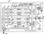
第1図にマルチメディア通信端末の基本的な構成例100を示す。この端末は、動画像と音声とデータに関する双方向通信を行う機能を持ち、蓄電池127により回路部128に電力を供給している。電池残量検出器131で検出された電池残量情報132は符号化モード制御部133に供給される。この符号化モード制御部133は、電池残量の情報等から適切な符号化モードを判断し、画像・音声コーデック110に符号化モード制御情報134を供給する。また、同様にクロック発生回路129から、クロック信号が本体の回路部全体に供給される。画像信号はカメラ101から、音声信号はマイク102からそれぞれ入力され、アナログ/ディジタル変換器106、107によりディジタル化される。このディジタル化された信号は画像・音声コーデック回路110に供給され、符号化部111で符号化される。画像符号化器112で得られた画像符号化ビットストリームは多重化回路121に供給される。同様に音声信号は音声符号化器115で符号化され、音声符号化ビットストリームとして多重化回路121に供給される。多重化回路121はさらにデータ入出力器105の出力信号を加えた3個の信号を多重化する。その多重信号出力(多重化回路121の出力)は通信符号化器123を経て送信信号125として通信路へ出力される。
一方通信路からの受信信号126は通信路復号化器124を経て分離回路122へ供給され、画像符号化ビットストリーム、音声符号化ビットストリーム、データ信号に分離される。音声と画像の符号化ビットストリームは復号化部116に供給される。画像符号化ビットストリームは画像復号化器117において復号化される。ここで復号化されたディジタル復号画像は、ディジタル/アナログ変換器108を経てディスプレイ103で表示される。同様に音声符号化ビットストリームは音声復号化器120において復号化され、ディジタル化された復号音声となった後にディジタル/アナログ変換器109を経てスピーカ104から出力される。データ信号130はデータ入出力器105に加えられた後にパソコン等のデータ処理装置に出力される。
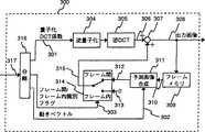
第1図の画像符号化器112の構成例として、第2図に通信用動画像符号化方式の国際標準であるH.261の符号化器200を示す。H.261は、符号化方式として、動き補償予測とDCT(離散コサイン変換)を組み合わせたハイブリッド符号化方式(フレーム間/フレーム内適応符号化方式)を採用している。
以下に、第2図を用いてこのハイブリッド符号化方式を説明する。減算器202は入力画像(現フレームの原画像)201とフレーム間/フレーム内符号化切り換えスイッチ219の出力画像213(後述)との差を計算し、誤差画像203を出力する。この誤差画像は、DCT変換器204でDCT係数に変換された後に量子化器205で量子化され、量子化DCT係数206となる。この量子化DCT係数206は伝送情報として通信路に出力されると同時に、符号化器内でもフレーム間予測処理部207において予測画像を合成するために使用される。次に予測画像合成の手順を説明する。上述の量子化DCT係数206は、逆量子化器208と逆DCT変換器209を経て復号誤差画像210(受信側で再生される誤差画像と同じ画像)となる。これに、加算器211においてフレーム間/フレーム内符号化切り換えスイッチ219の出力画像213(後述)が加えられ、現フレームの復号画像212(受信側で再生される現フレームの復号画像と同じ画像)を得る。この画像は一旦フレームメモリ214に蓄えられ、1フレーム分の時間だけ遅延される。したがって、現時点では、フレームメモリ214は前フレームの復号画像215を出力している。この前フレームの復号画像と現フレームの入力画像201が動き補償処理部216に入力され、ブロックマッチングとよばれるフレーム間予測の処理が行われる。ブロックマッチングでは、画像を複数のブロックに分割し、各ブロックごとに現フレームの原画像に最も似た部分を前フレームの復号画像から取り出すことにより、現フレームの予測画像217が合成される。このときに、各ブロックが前フレームと現フレームの間でどれだけ移動したかを検出する処理(動き推定処理)を行う必要がある。動き推定処理によって検出された各ブロックごとの動きベクトル220は、受信側へ伝送される。受信側は、この動きベクトルと前フレームの復号画像から、独自に送信側で得られるものと同じ予測画像を合成することができる。予測画像217は、「0」信号218と共にフレーム間/フレーム内符号化切り換えスイッチ219に入力される。このスイッチは、両入力のいずれかを選択することにより、フレーム間符号化とフレーム内符号化を切り換える。予測画像217が選択された場合(第2図はこの場合を表している)には、フレーム間符号化が行われる。一方、「0」信号が選択された場合には、入力画像がそのままDCT符号化されて通信路に出力されるため、フレーム内符号化が行われることになる。受信側が正しく復号化画像を得るためには、送信側でフレーム間符号化が行われたかフレーム内符号化が行われたかを知る必要がある。このため、識別フラグ221が通信路へ出力される。最終的なH.261符号化ビットストリーム223は多重化回路222で量子化DCT係数、動きベクトル、フレーム内/フレーム間識別フラグの情報を多重化することによって得られる。
H.261ではブロックごとに独立にフレーム間/フレーム内符号化の選択が行えるようになっている。フレーム内/フレーム間符号化のいずれを行うかの判断は符号化器に任されており、入力画像の性質に応じて符号効率が高くなると考えられる方を選ぶのが一般的である。一般にシーンチェンジ等により、連続するフレーム間の相関が低い場合には、フレーム内符号化を選択した方が効率が高くなると言われている。
第3図に第2図の符号化器が出力した符号化ビットストリームを受信する復号化器300(第1図の117に対応)の構成例を示す。受信したH.261ビットストリーム317は、分離回路316で量子化DCT係数301、動きベクトル302、フレーム内/フレーム間識別フラグ303に分離される。量子化DCT係数301は逆量子化器304と逆DCT変換器305を経て復号化された誤差画像306となる。この誤差画像は加算器307でフレーム間/フレーム内符号化切り換えスイッチ314の出力画像315を加算され、復号化画像308として出力される。フレーム間/フレーム内符号化切り換えスイッチはフレーム間/フレーム内符号化識別フラグ303に従って、出力を切り換える。フレーム間符号化を行う場合に用いる予測画像312は、予測画像合成部311において合成される。ここでは、フレームメモリ309に蓄えられている前フレームの復号画像310に対して、受信した動きベクトル302に従ってブロックごとに位置を移動させる処理が行われる。一方フレーム内符号化の場合、フレーム間/フレーム内符号化切り換えスイッチ314は、「0」信号313をそのまま出力する。
現在第2図および第3図に示した画像符号化器および復号化器は、各部の処理を専用に行う回路を持つ専用チップ用いて実現されることが多い。一方、従来の専用チップを用いた画像の符号化・復号化装置に代わる新しい実装形態として、最近汎用CPUを用いたソフトウェアによる符号化・復号化装置(ソフトウェアコーデック)が注目を集めている。ソフトウェアコーデックは装置の開発にかかる労力が少ないことや、機能や性能の変更に柔軟に対応できること等の特徴を持つことから、汎用CPUの高速化が進むにつれてその数が増えることが予想されている。
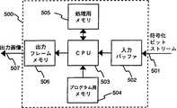
第4図と第5図に動画像用のソフトウェア符号化器400と復号化器500の構成例をそれぞれ示す。なお、400と500はそれぞれ第1図の112と117に対応している。ソフトウェア符号化器400では、まず入力画像401は入力フレームメモリ402に蓄えられ、CPU403はここから情報を読み込んで符号化の処理を行う。このCPUを駆動するためのプログラムはプログラム用メモリ404に蓄えられる。また、CPUは処理用メモリ405を活用して符号化の処理を行う。CPUが出力する符号化情報は一旦出力バッファ406に蓄えられた後に符号化ビットスリーム407として出力される。
一方、ソフトウェア復号化器500では、入力された符号化ビットストリーム501は一旦入力バッファ502に蓄えられた後にCPU503に読み込まれる。CPUはプログラム用メモリ504と処理用メモリ505を活用して復号化処理を行う。この結果得られた復号化画像は一旦出力フレームメモリ506に蓄えられた後に出力画像507として出力される。
第1図に示したマルチメディア通信端末が電力の残量に応じて符号化モードを制御する部分構成例を第6図、第7図、第8図に示す。以後、図面中で同じ参照番号は同じものを指す。
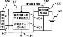
第6図に示す構成では、蓄電池127の残留電力量を電池残量検出部131が検出し、電池残量情報132として符号化モード制御部133に伝える。この情報132が、電池127の電池残量がある一定値を下回る事を示す情報である場合には、符号化モード制御部133を構成する警告表示制御部604は端末利用者606に警告は発する。警告を伝える手段は、例えば、ディスプレイへの警告文、警告記号等の視覚に訴える表示、ブザー音や合成音声の発生させる等の利用者の聴覚に訴える警告が考えられる。また、第1図の構成に更に警告ランプを設け点灯させることも有効である。電池残量が少なくなったことを知った端末利用者は、自らスイッチを切り換えるなどして符号化モードを変えることが可能となっている。この切り換え情報607を受け取った符号化モード切り換え部605は、端末利用者の指示にしたがって符号化モードを切り換える。端末利用者が符号化モードを切り換える際には、各符号化モードについて、そのモードで通信を続けた場合に予想される連続通信時間などの補助情報を示すこともできる。符号化モード切り換えの具体的な方法については後述する。
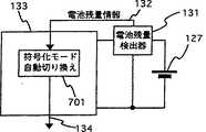
第6図の端末では利用者が符号化モードを切り換えていたのに対し、第7図に示す端末は電池残量情報に応じて符号化モード自動切り換え部701が自動的に符号化モードを切り換えることを特徴としている。このとき、電池残量がどのレベルになったときにどの符号化モードを採用するかについては、端末利用者が自らプログラミングできるようにしても良い。また、あらかじめプログラムされた複数のパターンの中から利用者が好みのものを選択できるようにしても良い。一般的な自動制御方法として、電池残量が少なくなるに従って、低消費電力・低品質モードへと移行する方式が考えられる。こうすることによって、通信時間の延長、電池切れによる突然の通信停止の防止等の効果が期待できる。
第8図は、情報を送信している端末の符号化モードを、通信路801を介して通話相手の端末802が制御する場合のシステム構成例である。例えば監視カメラを用いた監視システムなどにおいては、遠隔操作によりカメラの符号化モードを制御することが考えられる。また、監視カメラが多数ある場合には、受信側の端末が符号化モードを集中制御することにより、各々の監視カメラの構成を簡略化することができる。
第6図、第7図、第8図に示した符号化モード切り換えによる消費電力制御方式は、特に電力源として蓄電池を利用していなくても有効となる場合がある。たとえば監視カメラが多数存在する監視システムでは、全監視カメラの総消費電力を抑えるために、特に重要な情報を伝送していないと思われるカメラの符号化モードを低品質・低消費電力モードにすることが考えられる。
次に、符号化モードを切り換える具体的な方法に関して説明する。第1図のマルチメディア通信端末100の画像符号化器112および復号化器117として、第2図および第3図に示したH.261符号化器および復号化器を使用する。例えば、動画像の符号化モードとして、以下の4モードを用意する。
(1)フレーム内/フレーム間適応符号化による送受信。
(2)受信は(1)と同じ。送信はフレーム内符号化のみ。
(3)受信は(1)と同じ。送信は無し。
(4)画像の送受信は無し。
この場合、(1)の符号化モードを採用しているときは画像・音声コーデック回路内の全ての部分は稼働している。符号化モードを(1)から(2)に切り換えたときには、フレーム間予測処理部207が非稼働状態となる。次に符号化モードが(3)となったときには、さらに画像符号化器200の残りの部分が非稼働状態となる。最後に符号化モードが(4)となったときには、さらに画像復号化部117が非稼働状態となり、画像情報の送受信は全てストップする。符号化モードの番号が大きくなるほど非稼働部分が大きくなるため、結果的に消費電力は少なくなる。しかし、逆に消費電力の少ない符号化モードほど通信される情報の品質は低くなってしまう。第9図にこの方式における符号化モードと電池残量の関係の一例を示す。901は、電池が十分に充電された状態の電池残量(電力×時間)を1.0、電池が使用不可能となるときの電池残量を0.0としたときの電池残量を表すグラフである。例えば、電池残量が0.5を割ると、符号化モード(1)から(2)に変化する。処理を簡単にするため、符号化モードを切り換えるタイミングは電池残量が規定値を割った瞬間以後の最初のフレーム分割点からとするのが適当である。さらに細かい制御を意図するのであれば、この切り換え点はブロックマッチングのためのブロックの分割点や、スライス(画像の端から端まで左右に広がるブロックマッチングのためのブロックの列)の分割点とする方法もある。これらの分割点では、前後の処理単位(フレーム、スライス、ブロック)で独立した処理を行うことができるため、符号化モードの切り換えを行いやすい。利用者が符号化モードを切り換える場合も、同様に切り換えの要求が出た直後のフレーム、ブロック、スライスの分割点から符号化モードを切り換えるのが適当である。
第9図の例においては、各々の符号化モードの中で符号化に関するパラメータを変化させることによってさらに細かく消費電力を制御することができる。例えば(1)の符号化モード内で、送信する画像のフレームレートを下げる。すると画像符号化部が動作している時間を相対的に減少させることが可能となり、結果的に消費電力の減少させることができる。第10図にこの様子を示す。
1001はnフレーム/秒で符号化を行った場合の符号化部の動作状態である。斜線部分は符号化部が動作している時間である。これに対して、1002はn/2フレーム/秒で符号化を行ったときの動作状態である。フレームごとの処理は1/n秒で終了するため、画像符号化部は1/n秒おきに1/n秒間、停止状態に入ることができる。これと同様の制御は、画像の解像度(画素数)を変化させることによって行うことも可能である。
フレームレート、解像度以外に、フレーム内/フレーム間適応符号化においてフレーム内符号化が選択される頻度も消費電力を制御するためのパラメータとして利用することができる。フレーム内符号化が選択される頻度を上げるとフレーム間予測部が稼働する時間を相対的に減少させることが可能となり、消費電力を減らすことができる。また、フレーム間符号化においてブロックマッチングを行う際の、動きベクトルの探索範囲を狭くすることも消費電力を減少させるためには有効である。さらに、カラー画像の送信または受信を行うことができる端末が、白黒画像を送信または受信することにより、色差信号を扱う回路やメモリを非稼働状態にすることもできる。また、たとえカラー画像を符号化したビットストリームを受信したとしても、白黒情報だけを再生することによって同様の効果を得ることができる。しかし、フレームレート、解像度を下げること、フレーム内符号化が選択される頻度を上げること、ブロックマッチングの探索範囲を狭くすること、白黒画像を送受信・再生すること等は、すべて受信側で復号化される画像の品質を劣化させることにつながる。
以下では、非稼働状態となった回路の消費電力を減少させる際に回路的にどのような制御が行われるかについて説明する。非稼働状態となった回路が電力を消費しないようにする直接的な方法としては、パワートランジスタを用いて電力の供給を停止させる方法がある。この方法は有効であるが、回路全体を集積化する場合にはパワートランジスタが大きな面積を占めてしまうために問題が発生する。そこでクロック信号を停止する方法が考えられる。第11図はクロック信号の供給を停止することによってフレーム間予測部の稼働状態を切り換える回路の構成例である。第1図のマルチメディア通信端末100において、画像符号化器112として第2図に示したH.261符号化器200を用いるとする。この回路では、クロック信号発生器129で生成したクロック信号1101はAND回路1103を経由してフレーム間予測処理部207のクロック入力1104に供給される。符号化モード切り換え信号1102は、第6図と第8図の符号化モード切り換え部605または第7図の符号化モード自動切り換え部701から供給される。符号化モード切り換え信号を「1」としたときにはクロック信号がフレーム間予測部に達するが、「0」とした場合にはクロック信号は供給されない。クロック信号が供給されないことによってフレーム間予測部は停止状態となり、結果としてこの部分の電力消費量を抑えることが可能となる。
一方、ソフトウェアコーデックでは画像符号化・復号化の処理のほとんどをCPUが行うために、稼働していない回路を停止することによって消費電力を制御する方法を使うことは難しい。そこで、CPUに供給されるクロック信号の周波数を制御することが考えられる。上で述べたフレームレートの低下、フレーム内符号化を行う頻度の上昇、画像送信の停止、画像受信の停止等の制御は、ソフトウェアコーデックではCPUの処理量の減少につながる。したがって、減少した処理量の分だけクロック周波数を低下させても処理のリアルタイム性は確保することができる。一般的に汎用CPUは、動作クロックの周波数が低くなるほど消費電力が少なくなることが知られている。したがって、クロック周波数を制御することは、消費電力を制御することにつながる。第12図は符号化モードに応じてCPUクロックを切り換えるソフトウェア符号化器のクロック制御回路の構成例である。第1図のマルチメディア通信端末100において、画像符号化器112として第4図に示したソフトウェア符号化器400を用いる。符号化モード切り換え信号1102は、符号化モード指令レジスタ1209の状態を変化させる。符号化モード指令レジスタの内容1208は、ある特定のメモリアドレスを読みに行くことによってCPU403が読み出すことができるようになっている。上で述べた通り、符号化モードの切り換えを行う切り換え点は限られており(上述のフレーム、スライス、ブロック分割点)、CPUは切り換え点の処理を行う直前にのみ、符号化モード指令レジスタの内容を読み込めば良い。この符号化モード指令レジスタの内容を通じてCPUは符号化モード切り換えの指令が発せられたことを検知し、ソフトウェア的に符号化モードをある切り換え点で切り換える。なお、CPUに符号化モード切り換えの要求を行う処理はCPUへの割り込みを使うことによって達成することもできる。符号化モードを切り換えたCPUは、CPU自身が現在どの符号化モードで処理を行っているかを外部の回路に知らせるためにCPU符号化モードレジスタ1205にCPU符号化モード1206を書き込む。クロック分周部1203はこのCPU符号化モードレジスタの内容1202を読み込み、現在のCPUの符号化モードに応じてクロック信号発生器129で生成したクロック信号1101の分周率(周波数を落とす割合)を制御する。こうすることによってCPUに供給されるクロック信号1204の周波数が符号化モードに応じて制御される。なお、この部分の処理はVCO(Voltage Controlled Oscillator)を用いるなどしてクロックの発振周波数自体を制御することによっても実現できる。
このようにクロック信号を制御する方式は、専用チップを用いた装置に対しても応用できる。例えばフレームレートを下げる制御を行った場合には、第10図に示した方式を用いずに符号化装置自体の動作クロックを落として消費電力を減らすことも可能である。
なお、本明細書では符号化モードの変化として同一の符号化方式(例えばH.261)の中における変化を扱ってきた。しかし、符号化方式自体を変化させること(例えば、MPEG1からH.261への変化)も、同様に符号化モードの変化として、本発明の枠組みに含まれることは明らかである。
産業上の利用可能性
本発明により、端末が送信する符号化された情報の品質を意図的に低下させることによって、端末が消費する電力量を低減させることができる。本発明の通信端末装置は、例えば、蓄電池を使用する携帯用の通信端末装置、消費電力を抑えつつ画像の伝送継続時間を主体として考慮されるべき画像監視装置、等に用いられて有用である。Technical field
The present invention relates to a multimedia communication terminal apparatus having a plurality of encoding modes with different power consumption. In the present invention, the change of the coding mode means that the coded bits transmitted even when the same input information source (for example, an image input to the camera, an audio input to the microphone, etc.) is given at the terminal. This refers to a change in the state of the terminal as the stream changes. In the present invention, a terminal that performs communication of single information such as voice is also included in the multimedia communication terminal.
Background art
The spread of multimedia communication terminals capable of performing digital image communication is in full swing. Major factors that have brought about the practical application of digital image communication include the development of image information compression technology (image coding technology) in addition to the development of electronic device technology. The image encoding technique is a technique for compressing image information, which is said to have an information amount 1000 times that of audio, to a level at which transmission and storage are possible. When digital image communication using image coding technology is performed, the terminal on the transmission side encodes (compresses) the input image information, converts it into an encoded bit stream, and transmits it, and the terminal on the reception side receives it. A decoded image is obtained by decoding the bitstream. At this time, in order to perform communication correctly, it is necessary for terminals located at both ends of the communication path to adopt a common image coding method. Therefore, standard image encoding methods such as H.261, MPEG1, and MPEG2 are currently defined as international standards. In the future, it is expected that more standard encoding methods will be defined for new applications such as wireless image communication.
Already commercialized image communication terminals are mainly wired image communication terminals connected to analog telephone lines, ISDN lines, and the like. However, in the future, it is expected that wireless image communication terminals that can provide a similar function also in a wireless line will be widespread. Since the wireless communication terminal is characterized by its portability, a storage battery is usually used as a power source. However, there is a limit to the amount of power that can be supplied by one metered storage battery used in a portable terminal, and it is necessary to reduce the power consumption of the terminal in order to increase the continuous communication time. In addition, since many terminals are used in a monitoring system or the like, it is important to suppress power consumption even when a storage battery is not used. As described above, power saving is an important condition for some applications. On the other hand, an image coding algorithm having a high information compression rate has a large amount of calculation and tends to increase power consumption. In general, up to now, the main purpose of image coding is to increase the information compression rate, and power consumption has not been a major problem. However, in the future when multimedia communication terminals will become widespread and will be used for various purposes, power consumption problems that have been overlooked so far will occupy an important position in the design and development of devices. It is expected that
As measures for power saving in portable devices that have already been put into practical use, some contrivances can be seen in notebook (laptop) computers. For example, the main power saving functions of Apple's Macintosh PowerBook180c are shown below.
(A) The backlight of the liquid crystal display is automatically darkened when the remaining battery level is less than a certain amount.
(B) When the remaining battery level falls below a certain level, a warning message is displayed on the display.
(C) If the device is left for a certain period of time with the power on, it automatically enters a sleep mode (a state in which all functions other than holding the stored contents of the RAM are stopped).
(D) The user can switch the clock frequency of the CPU, and power can be saved by reducing the processing speed.
(E) When there is no processing request to the CPU for a certain period of time, the CPU clock frequency is automatically lowered. Such power consumption countermeasures in a laptop computer cause the screen to become difficult to see and the processing speed to decrease. However, in general, the processing content itself and the information itself (for example, information displayed on the screen itself) are not changed.
In general, an encoding algorithm having a high information compression rate performs a complicated process, and thus tends to increase the amount of processing (calculation amount). An increase in the amount of calculation causes an increase in power consumption. For example, a multimedia communication terminal that uses a power source as a storage battery or a communication terminal that requires a reduction in power consumption results in shortening the continuous communication time. End up.
Therefore, an object of the present invention is to provide a communication terminal that can save power consumption and secure a necessary continuous call time. In particular, it is an object to provide a communication terminal that reduces the power consumption by changing the encoding mode.
Disclosure of the invention
In order to achieve the above object, the communication terminal of the present invention consumes power by switching the coding mode to a mode requested from the system or the outside among image information or audio information of a plurality of different coding modes. To control.
A specific communication terminal device of the present invention encodes an input image or audio information, outputs the encoded image or audio information to a communication channel, and decodes the image or audio information obtained from the transmission channel. Input means (101,102,106,107) for inputting input information such as, a communication path control unit (123,124) for outputting the input information to the communication path and inputting information from the communication path, and information obtained from the communication path A code that is provided between output means (103, 104, 108, 109, 105) that outputs images or sounds, etc., and between the input means, the output means, and the communication path control unit, and has a different power consumption during execution. Codec means for encoding the input information according to the encoding mode and decoding the information input from the communication path, and a control unit for controlling the selection of the encoding mode (133) It is.
In order to reduce the power consumption of the communication terminal device, for example, the quality of transmitted information is controlled. For quality control, a means for switching automatically or a means for switching manually is provided. It is also possible for the communication partner to perform an encoding mode switching operation even during communication. It has a means to monitor the remaining battery capacity of the storage battery used as a power source, and to provide an indication of the continuous callable time when the mode is used for each encoding mode to the person who performs the encoding mode switching, with good timing It is also effective to switch the encoding mode. Further, there is provided means for selecting an encoding mode with less power consumption as the detected remaining battery level decreases. It is also effective to provide means for stopping a clock signal provided to a circuit that has become unnecessary by switching the encoding mode. With respect to the clock signal, it is also effective to include means for performing control to lower the frequency of the clock signal provided to the encoding circuit as the processing amount of the operating encoding mode is smaller. It is also effective to control the resolution with low power consumption by providing means for controlling the resolution during image transmission.
Taking moving image coding as an example, the coding mode includes fixed intra-frame coding and inter-frame / intra-frame adaptive coding mode, and selects a fixed intra-frame coding mode or inter-frame coding. / Intra-frame adaptive coding mode is effective for reducing power consumption by increasing the frequency of intra-frame adaptive coding.
When performing inter-frame coding, a means for performing motion compensation based on block matching is provided to reduce the number of search motion vectors for each block in block matching. Alternatively, a means for controlling the frame rate of an image transmitted with respect to moving image coding is provided, and lowering the frame rate is also effective in reducing power consumption.
When both image and sound communication can be performed, power saving and sudden data loss can be prevented by preferentially performing communication using only sound.
Transmission / reception of monochrome image information in a communication terminal apparatus capable of transmitting / receiving color image information is also effective in reducing power consumption.
When receiving the coding mode switching request, the codec means at the frame dividing point immediately after the coding mode switching request, the slice dividing point, or the block dividing point for block matching. What is necessary is just to switch an encoding mode.
If control is performed to reduce power consumption when the remaining battery level is low, a warning is given to the user and the remaining call time can be extended. Further, by selecting an optimal encoding method from the remaining battery level and the desired call time, it is possible to use the encoding method with the highest image quality as long as the call time is not shorter than desired.
[Brief description of the drawings]
FIG. 1 is a diagram showing an example of the configuration of a multimedia communication terminal, FIG. 2 is a diagram showing an example of the configuration of an H.261 image encoder, and FIG. 3 is an image decoding of H.261. FIG. 4 is a diagram illustrating a configuration example of a software image encoder, FIG. 5 is a diagram illustrating a configuration example of a software image decoder, and FIG. FIG. 7 shows a configuration example of a multimedia communication terminal in which the terminal user switches the encoding mode, FIG. 7 shows a configuration example of the multimedia communication terminal that automatically switches the encoding mode, and FIG. FIG. 9 shows a configuration example of a multimedia communication terminal in which the communication partner switches the encoding mode, FIG. 9 shows an example of how the encoding mode changes according to the remaining battery level, and FIG. FIG. 11 is a diagram showing an operation state of image encoding when the frame note is changed. Fig. 12 shows a configuration example of a circuit that stops the inter-frame prediction unit by stopping the supply of the clock signal, and Fig. 12 shows the CPU periphery of the software codec that controls the power consumption by changing the clock frequency It is the figure which showed the structural example of this circuit.
BEST MODE FOR CARRYING OUT THE INVENTION
FIG. 1 shows a basic configuration example 100 of a multimedia communication terminal. This terminal has a function of performing bidirectional communication regarding moving images, sounds, and data, and supplies power to the
On the other hand, the received
As an example of the configuration of the
Hereinafter, this hybrid encoding method will be described with reference to FIG. The
In H.261, inter-frame / intra-frame coding can be selected independently for each block. The determination of whether to perform intra-frame / inter-frame encoding is left to the encoder, and it is common to select the one that is considered to increase the code efficiency according to the nature of the input image. In general, when the correlation between consecutive frames is low due to a scene change or the like, it is said that the efficiency is higher when intra-frame coding is selected.
FIG. 3 shows a configuration example of a decoder 300 (corresponding to 117 in FIG. 1) that receives the encoded bit stream output from the encoder of FIG. The received H.261
Currently, the image encoder and decoder shown in FIGS. 2 and 3 are often realized by using a dedicated chip having a circuit dedicated to processing of each unit. On the other hand, software-based encoding / decoding devices (software codecs) using a general-purpose CPU have recently attracted attention as a new implementation form that replaces conventional image encoding / decoding devices using dedicated chips. Software codecs are expected to increase in number as the speed of general-purpose CPUs increases because they have features such as less equipment development and flexible response to changes in functions and performance. .
FIG. 4 and FIG. 5 show configuration examples of the moving
On the other hand, in the
Examples of partial configurations in which the multimedia communication terminal shown in FIG. 1 controls the encoding mode in accordance with the remaining amount of power are shown in FIGS. Hereinafter, the same reference numerals refer to the same parts in the drawings.
In the configuration shown in FIG. 6, the remaining battery
In the terminal shown in FIG. 6, the user switches the encoding mode, whereas in the terminal shown in FIG. 7, the encoding mode
FIG. 8 shows an example of a system configuration when the
The power consumption control method by switching the coding mode shown in FIGS. 6, 7, and 8 may be effective even when a storage battery is not used as a power source. For example, in a surveillance system with a large number of surveillance cameras, to reduce the total power consumption of all surveillance cameras, the encoding mode of the camera that seems not to transmit particularly important information should be set to a low quality / low power consumption mode. It is possible.
Next, a specific method for switching the encoding mode will be described. As the
(1) Transmission / reception by intraframe / interframe adaptive encoding.
(2) Reception is the same as (1). Transmission is only intra-frame coding.
(3) Reception is the same as (1). No transmission.
(4) No image transmission / reception.
In this case, when the encoding mode (1) is adopted, all parts in the image / audio codec circuit are operating. When the encoding mode is switched from (1) to (2), the inter-frame
In the example of FIG. 9, the power consumption can be controlled more finely by changing the parameters relating to encoding in each encoding mode. For example, the frame rate of the image to be transmitted is lowered within the encoding mode (1). Then, it is possible to relatively reduce the time during which the image encoding unit is operating, and as a result, it is possible to reduce power consumption. Figure 10 shows this situation.
In addition to the frame rate and resolution, the frequency with which intra-frame coding is selected in intra-frame / inter-frame adaptive coding can also be used as a parameter for controlling power consumption. Increasing the frequency with which intra-frame coding is selected makes it possible to relatively reduce the time during which the inter-frame prediction unit operates, thereby reducing power consumption. In addition, narrowing the motion vector search range when performing block matching in interframe coding is also effective in reducing power consumption. Furthermore, a terminal that can transmit or receive a color image can transmit or receive a monochrome image, thereby disabling a circuit or memory that handles color difference signals. Even if a bit stream obtained by encoding a color image is received, the same effect can be obtained by reproducing only the black and white information. However, lowering the frame rate and resolution, increasing the frequency with which intra-frame coding is selected, narrowing the search range for block matching, sending and receiving / reproducing black and white images, etc. are all decoded on the receiving side. This leads to deterioration of the quality of the image to be displayed.
Below, what kind of control is performed in a circuit when reducing the power consumption of the circuit which became the non-operation state is demonstrated. As a direct method for preventing the circuit that has become non-operating from consuming power, there is a method of stopping the supply of power using a power transistor. This method is effective, but a problem arises when the entire circuit is integrated because the power transistor occupies a large area. Therefore, a method of stopping the clock signal can be considered. FIG. 11 is a configuration example of a circuit that switches the operating state of the inter-frame prediction unit by stopping the supply of the clock signal. In the
On the other hand, with a software codec, the CPU performs most of the image encoding / decoding process, so it is difficult to use a method of controlling power consumption by stopping circuits that are not operating. Therefore, it is conceivable to control the frequency of the clock signal supplied to the CPU. Controls such as a decrease in the frame rate, an increase in the frequency of intra-frame encoding, a stop of image transmission, and a stop of image reception described above lead to a decrease in the CPU processing amount in the software codec. Therefore, even if the clock frequency is lowered by the reduced amount of processing, the real-time processing can be ensured. In general, it is known that a general-purpose CPU consumes less power as the operating clock frequency is lower. Therefore, controlling the clock frequency leads to controlling power consumption. FIG. 12 is a configuration example of the clock control circuit of the software encoder that switches the CPU clock according to the encoding mode. In the
The method for controlling the clock signal in this way can also be applied to a device using a dedicated chip. For example, when control for lowering the frame rate is performed, it is possible to reduce power consumption by reducing the operation clock of the encoding apparatus itself without using the method shown in FIG.
In the present specification, changes in the same encoding method (for example, H.261) have been dealt with as changes in the encoding mode. However, it is clear that changing the encoding method itself (for example, changing from MPEG1 to H.261) is also included in the framework of the present invention as a change in encoding mode.
Industrial applicability
According to the present invention, it is possible to reduce the amount of power consumed by a terminal by intentionally reducing the quality of encoded information transmitted by the terminal. The communication terminal device of the present invention is useful for use in, for example, a portable communication terminal device using a storage battery, an image monitoring device that should be considered based on the transmission duration of an image while suppressing power consumption, and the like. .
Claims (17)
Translated fromJapanese上記制御部は該供給手段の電池残量に応じて上記出力手段を用いて画像又は音声メッセージを出力し、該メッセージに対して入力された制御信号に応じて、上記符号化モードの選択制御を行なうことを特徴とする通信端末装置。An input means for inputting input information such as an image or sound in a communication terminal device that encodes the input image or sound information and outputs the encoded image or sound information to the communication path and decodes the image or sound information obtained from thecommunication path ; A communication path control unit that outputs the input information to the communication path and inputs information from the communication path, an output means that outputs information obtained from the communication path as an image or sound, the input means, and the output Provided between the communication means and the communication path control unit, and at the time of execution, the input information is encoded according to one of a plurality of encoding modes having different power consumption, and the information input from the communication path is decoded. Codec means,supply means for supplying power to the entireapparatus, and a control unit for controlling the selection of the encoding mode,
The control unitoutputsthe image or voice message by usingtheoutput handsstagecorresponding to the battery remaining amounts of the feedmeans,according to the input control signal tosaidmessage,the codingmode communication terminalequipment, characterized in that for selectingcontrol.
Applications Claiming Priority (1)
| Application Number | Priority Date | Filing Date | Title |
|---|---|---|---|
| PCT/JP1995/000376WO1996027987A1 (en) | 1995-03-08 | 1995-03-08 | Portable terminal for multimedia communication |
Publications (1)
| Publication Number | Publication Date |
|---|---|
| JP3623967B2true JP3623967B2 (en) | 2005-02-23 |
Family
ID=14125703
Family Applications (1)
| Application Number | Title | Priority Date | Filing Date |
|---|---|---|---|
| JP52675396AExpired - Fee RelatedJP3623967B2 (en) | 1995-03-08 | 1995-03-08 | Portable multimedia communication terminal device |
Country Status (3)
| Country | Link |
|---|---|
| US (1) | US5949484A (en) |
| JP (1) | JP3623967B2 (en) |
| WO (1) | WO1996027987A1 (en) |
Families Citing this family (96)
| Publication number | Priority date | Publication date | Assignee | Title |
|---|---|---|---|---|
| JP3019787B2 (en)* | 1996-09-20 | 2000-03-13 | 日本電気株式会社 | Motion vector detection device |
| JP3024587B2 (en) | 1997-04-11 | 2000-03-21 | 日本電気株式会社 | Portable information terminal |
| JPH10304578A (en)* | 1997-04-21 | 1998-11-13 | Canon Inc | Electrical equipment and operation control method for electrical equipment |
| CA2240118C (en)* | 1997-06-09 | 2005-11-22 | Hitachi Ltd. | Image sequence coding method and decoding method |
| US6028631A (en)* | 1997-09-08 | 2000-02-22 | Hitachi, Ltd. | Portable terminal apparatus for multimedia communication |
| JP3719482B2 (en)* | 1998-07-29 | 2005-11-24 | 株式会社デンソー | Wireless communication device |
| JP4408467B2 (en)* | 1998-10-30 | 2010-02-03 | 富士フイルム株式会社 | Digital camera and operation control method thereof |
| JP2000253303A (en)* | 1999-02-26 | 2000-09-14 | Minolta Co Ltd | Battery driven digital camera and electronic instrument |
| US6275712B1 (en)* | 1999-02-26 | 2001-08-14 | Nokia Mobile Phones Ltd | Mobile station control states based on available power |
| JP4809960B2 (en)* | 1999-04-12 | 2011-11-09 | キヤノン株式会社 | Image processing apparatus, method, and recording medium |
| JP2000341222A (en)* | 1999-05-27 | 2000-12-08 | Sony Corp | Communication terminal and host device |
| US6385469B1 (en)* | 1999-06-22 | 2002-05-07 | Ericsson Inc. | System and method for providing battery gapping for mobile stations |
| US6668299B1 (en) | 1999-09-08 | 2003-12-23 | Mellanox Technologies Ltd. | Software interface between a parallel bus and a packet network |
| JP2001086512A (en)* | 1999-09-14 | 2001-03-30 | Nec Corp | Variable bit rate encoder |
| JP2001103565A (en)* | 1999-09-30 | 2001-04-13 | Toshiba Corp | Mobile wireless terminal |
| US6909744B2 (en)* | 1999-12-09 | 2005-06-21 | Redrock Semiconductor, Inc. | Processor architecture for compression and decompression of video and images |
| KR100683380B1 (en)* | 2000-02-21 | 2007-02-15 | 주식회사 팬택앤큐리텔 | Method and apparatus for transform and inverse transform for image compression coding |
| US6728312B1 (en)* | 2000-04-13 | 2004-04-27 | Forgent Networks, Inc. | Adaptive video decoding and rendering with respect to processor congestion |
| US7630721B2 (en)* | 2000-06-27 | 2009-12-08 | Ortiz & Associates Consulting, Llc | Systems, methods and apparatuses for brokering data between wireless devices and data rendering devices |
| JP2002027145A (en)* | 2000-07-05 | 2002-01-25 | Toshiba Corp | Wireless communication terminal |
| GB2366467B (en)* | 2000-08-23 | 2003-11-26 | Motorola Inc | Mobile terminal battery power conservation |
| US6910139B2 (en)* | 2000-10-02 | 2005-06-21 | Fujitsu Limited | Software processing apparatus with a switching processing unit for displaying animation images in an environment operating base on type of power supply |
| US7043058B2 (en)* | 2001-04-20 | 2006-05-09 | Avid Technology, Inc. | Correcting motion vector maps for image processing |
| US6968006B1 (en) | 2001-06-05 | 2005-11-22 | At&T Corp. | Method of content adaptive video decoding |
| US6810086B1 (en) | 2001-06-05 | 2004-10-26 | At&T Corp. | System and method of filtering noise |
| US6909745B1 (en)* | 2001-06-05 | 2005-06-21 | At&T Corp. | Content adaptive video encoder |
| US7773670B1 (en) | 2001-06-05 | 2010-08-10 | At+T Intellectual Property Ii, L.P. | Method of content adaptive video encoding |
| US6970513B1 (en) | 2001-06-05 | 2005-11-29 | At&T Corp. | System for content adaptive video decoding |
| US7062303B2 (en)* | 2001-07-05 | 2006-06-13 | Intel Corporation | Synchronizing power conservation modes |
| FR2827054B1 (en)* | 2001-07-06 | 2003-12-12 | Nec Technologies Uk Ltd | METHOD FOR MONITORING AND MANAGING THE BATTERY CONDITION OF A PORTABLE MULTIMEDIA DEVICE |
| US7519985B2 (en)* | 2001-07-30 | 2009-04-14 | Sony Corporation | Radio communication system, radio communication control apparatus, radio communication control method, recording medium, and computer program |
| WO2003024137A1 (en)* | 2001-09-13 | 2003-03-20 | Nokia Corporation | Signal processing device and signal processing method |
| JP4167486B2 (en)* | 2001-12-28 | 2008-10-15 | 松下電器産業株式会社 | Data reproducing apparatus and data reproducing method |
| JP2003209845A (en)* | 2002-01-11 | 2003-07-25 | Mitsubishi Electric Corp | Image coding integrated circuit |
| JP3779215B2 (en)* | 2002-01-28 | 2006-05-24 | 富士通株式会社 | Portable information processing device |
| US7000126B2 (en)* | 2002-04-18 | 2006-02-14 | Intel Corporation | Method for media content presentation in consideration of system power |
| JP4265204B2 (en)* | 2002-11-18 | 2009-05-20 | 日本電気株式会社 | Information communication terminal with videophone function and videophone display switching method |
| WO2004068835A2 (en)* | 2003-01-29 | 2004-08-12 | Koninklijke Philips Electronics N.V. | Method of video coding for handheld apparatus |
| US20040158878A1 (en)* | 2003-02-07 | 2004-08-12 | Viresh Ratnakar | Power scalable digital video decoding |
| JP2004343663A (en)* | 2003-05-19 | 2004-12-02 | Sony Corp | Imaging device |
| US20040247993A1 (en)* | 2003-05-21 | 2004-12-09 | Sony Ericsson Mobile Communications Ab | System and Method of Improving Talk-Time at the End of Battery Life |
| EP1652367A1 (en)* | 2003-07-24 | 2006-05-03 | Koninklijke Philips Electronics N.V. | Mobile device with display device and image acquisition unit |
| US7463886B2 (en)* | 2003-09-16 | 2008-12-09 | Spyder Navigations L.L.C. | Method and system for supporting residual energy awareness in an ad hoc wireless communications network |
| JP2005184632A (en)* | 2003-12-22 | 2005-07-07 | Nec Access Technica Ltd | Power consumption reduction method in communication terminal, and communication terminal |
| GB0400658D0 (en)* | 2004-01-13 | 2004-02-11 | Koninkl Philips Electronics Nv | Portable device for receiving media content |
| GB2411328B (en)* | 2004-02-23 | 2007-05-16 | Toshiba Res Europ Ltd | Adaptive MIMO systems |
| US7639743B2 (en)* | 2004-03-25 | 2009-12-29 | Sony Corporation | Image decoder and image decoding method and program |
| US7734310B2 (en)* | 2004-07-08 | 2010-06-08 | Panasonic Corporation | Mobile terminal device |
| JP2006203724A (en)* | 2005-01-24 | 2006-08-03 | Toshiba Corp | Image compression apparatus and image compression method |
| US7953283B2 (en)* | 2005-01-27 | 2011-05-31 | Panasonic Corporation | Portable terminal |
| US9325781B2 (en) | 2005-01-31 | 2016-04-26 | Invention Science Fund I, Llc | Audio sharing |
| US20060170956A1 (en) | 2005-01-31 | 2006-08-03 | Jung Edward K | Shared image devices |
| US9124729B2 (en) | 2005-01-31 | 2015-09-01 | The Invention Science Fund I, Llc | Shared image device synchronization or designation |
| US9910341B2 (en) | 2005-01-31 | 2018-03-06 | The Invention Science Fund I, Llc | Shared image device designation |
| US8606383B2 (en) | 2005-01-31 | 2013-12-10 | The Invention Science Fund I, Llc | Audio sharing |
| US9082456B2 (en) | 2005-01-31 | 2015-07-14 | The Invention Science Fund I Llc | Shared image device designation |
| US9489717B2 (en) | 2005-01-31 | 2016-11-08 | Invention Science Fund I, Llc | Shared image device |
| US8902320B2 (en) | 2005-01-31 | 2014-12-02 | The Invention Science Fund I, Llc | Shared image device synchronization or designation |
| TW200638188A (en)* | 2005-04-18 | 2006-11-01 | Wistron Corp | Power saving method for notebook computer |
| US8964054B2 (en) | 2006-08-18 | 2015-02-24 | The Invention Science Fund I, Llc | Capturing selected image objects |
| US9621749B2 (en) | 2005-06-02 | 2017-04-11 | Invention Science Fund I, Llc | Capturing selected image objects |
| US10003762B2 (en) | 2005-04-26 | 2018-06-19 | Invention Science Fund I, Llc | Shared image devices |
| US9191611B2 (en) | 2005-06-02 | 2015-11-17 | Invention Science Fund I, Llc | Conditional alteration of a saved image |
| US20070139529A1 (en)* | 2005-06-02 | 2007-06-21 | Searete Llc, A Limited Liability Corporation Of The State Of Delaware | Dual mode image capture technique |
| US9076208B2 (en) | 2006-02-28 | 2015-07-07 | The Invention Science Fund I, Llc | Imagery processing |
| US9967424B2 (en) | 2005-06-02 | 2018-05-08 | Invention Science Fund I, Llc | Data storage usage protocol |
| US9942511B2 (en) | 2005-10-31 | 2018-04-10 | Invention Science Fund I, Llc | Preservation/degradation of video/audio aspects of a data stream |
| US9819490B2 (en) | 2005-05-04 | 2017-11-14 | Invention Science Fund I, Llc | Regional proximity for shared image device(s) |
| US9001215B2 (en)* | 2005-06-02 | 2015-04-07 | The Invention Science Fund I, Llc | Estimating shared image device operational capabilities or resources |
| US20070222865A1 (en) | 2006-03-15 | 2007-09-27 | Searete Llc, A Limited Liability Corporation Of The State Of Delaware | Enhanced video/still image correlation |
| US9451200B2 (en) | 2005-06-02 | 2016-09-20 | Invention Science Fund I, Llc | Storage access technique for captured data |
| JP4505740B2 (en)* | 2005-05-16 | 2010-07-21 | ソニー株式会社 | Imaging apparatus and method for starting the same |
| JP2007013302A (en)* | 2005-06-28 | 2007-01-18 | Konica Minolta Holdings Inc | Two-way communication system |
| TWI282235B (en)* | 2005-11-15 | 2007-06-01 | Inst Information Industry | Intelligent power-saving communication mode switching subsystem and method thereof |
| TWI286024B (en)* | 2006-01-18 | 2007-08-21 | Inst Information Industry | Communication system, method for extending stand-by time, and computer readable medium therefor |
| JP2007228049A (en)* | 2006-02-21 | 2007-09-06 | Pentax Corp | Imaging device control unit and digital camera |
| JP5170972B2 (en)* | 2006-03-28 | 2013-03-27 | 株式会社東芝 | Wireless communication apparatus and wireless communication system |
| US7818106B1 (en) | 2006-04-13 | 2010-10-19 | Honda Motor Co., Ltd. | Motor vehicle power management system |
| US7925136B2 (en) | 2006-05-25 | 2011-04-12 | Qualcomm Incorporated | Method and apparatus for recording information in battery operated devices |
| US7933571B2 (en)* | 2007-06-20 | 2011-04-26 | Motorola Mobility, Inc. | Method and apparatus for selecting a communication mode based on energy sources in a hybrid power supply |
| US8228992B2 (en)* | 2007-10-12 | 2012-07-24 | Broadcom Corporation | Method and system for power-aware motion estimation for video processing |
| EP2051157A1 (en) | 2007-10-15 | 2009-04-22 | Research In Motion Limited | Method and System for Enabling or Disabling Features Based on a Battery Level Threshold |
| US20090098914A1 (en)* | 2007-10-15 | 2009-04-16 | Research In Motion Limited | Method and system for enabling or disabling features based on a battery level threshold |
| TW201001155A (en)* | 2008-06-24 | 2010-01-01 | Qisda Corp | Digital frame and power saving method thereof |
| US8667162B2 (en)* | 2008-12-31 | 2014-03-04 | Industrial Technology Research Institute | Method, apparatus and computer program product for providing a mobile streaming adaptor |
| US20130002798A1 (en)* | 2010-03-18 | 2013-01-03 | Nec Corporation | Mobile telephone set having video-phone function low in amount of heat generation |
| CN102547272B (en)* | 2010-12-30 | 2015-03-11 | 中国移动通信集团公司 | Decoding method, device and terminal |
| EP2870770A2 (en) | 2012-07-09 | 2015-05-13 | VID SCALE, Inc. | Power aware video decoding and streaming |
| US9980057B2 (en)* | 2012-07-19 | 2018-05-22 | Cochlear Limited | Predictive power adjustment in an auditory prosthesis |
| US10750294B2 (en) | 2012-07-19 | 2020-08-18 | Cochlear Limited | Predictive power adjustment in an auditory prosthesis |
| US9184778B2 (en) | 2013-02-22 | 2015-11-10 | Nissan North America, Inc. | Vehicle information gathering system |
| US9426439B2 (en)* | 2013-03-12 | 2016-08-23 | Intel Corporation | Exposing media processing features |
| JP2016158117A (en)* | 2015-02-25 | 2016-09-01 | シャープ株式会社 | Terminal device |
| WO2016158401A1 (en)* | 2015-03-30 | 2016-10-06 | ソニー株式会社 | Image encoding device and method |
| JP6878965B2 (en)* | 2017-03-07 | 2021-06-02 | 株式会社リコー | Information processing device, control method of information processing device, and program |
| CN117133183A (en)* | 2022-05-26 | 2023-11-28 | 川奇光电科技(扬州)有限公司 | Electronic paper display, logistics box and logistics state management method |
Family Cites Families (4)
| Publication number | Priority date | Publication date | Assignee | Title |
|---|---|---|---|---|
| DE4126105A1 (en)* | 1991-08-07 | 1993-02-11 | Standard Elektrik Lorenz Ag | RADIO PHONE |
| JP3255995B2 (en)* | 1992-10-23 | 2002-02-12 | 株式会社日立製作所 | Videophone equipment |
| JP3288085B2 (en)* | 1992-10-23 | 2002-06-04 | 株式会社日立製作所 | Portable information communication device |
| JPH06334998A (en)* | 1993-05-25 | 1994-12-02 | Hitachi Ltd | Portable visual telephone |
- 1995
- 1995-03-08JPJP52675396Apatent/JP3623967B2/ennot_activeExpired - Fee Related
- 1995-03-08WOPCT/JP1995/000376patent/WO1996027987A1/enactiveApplication Filing
- 1995-03-08USUS08/913,161patent/US5949484A/ennot_activeExpired - Lifetime
Also Published As
| Publication number | Publication date |
|---|---|
| WO1996027987A1 (en) | 1996-09-12 |
| US5949484A (en) | 1999-09-07 |
Similar Documents
| Publication | Publication Date | Title |
|---|---|---|
| JP3623967B2 (en) | Portable multimedia communication terminal device | |
| US6028631A (en) | Portable terminal apparatus for multimedia communication | |
| JP4777988B2 (en) | Mobile device | |
| US7317837B2 (en) | Encoding apparatus, video camera | |
| US7480333B2 (en) | Method and system for transcoding video data | |
| US20100027663A1 (en) | Intellegent frame skipping in video coding based on similarity metric in compressed domain | |
| US7327784B2 (en) | Method and system for transcoding video data | |
| US20060143615A1 (en) | Multimedia processing system and multimedia processing method | |
| JP2003061100A (en) | Apparatus and method for encoding multi-channel image | |
| JPH089347A (en) | Video transmission equipment | |
| TWI280060B (en) | Video encoder and method for detecting and encoding noise | |
| CN100385944C (en) | Multimedia receiving terminal and multimedia sending terminal | |
| EP1450263B1 (en) | Integrated circuit and electric device use thereof | |
| US7760198B2 (en) | Display controller | |
| JP2004289745A (en) | Moving image decoding method and apparatus | |
| JP2000341222A (en) | Communication terminal and host device | |
| JP2737690B2 (en) | Video communication system | |
| JP2000115777A (en) | Image processing method and image processing apparatus | |
| JP3674454B2 (en) | Video playback system and display control apparatus | |
| KR0174399B1 (en) | Video bitrate control device and method | |
| JP4367272B2 (en) | Encoding and decoding apparatus, encoding apparatus, and decoding apparatus | |
| KR100397133B1 (en) | Method and System for compressing/transmiting of a picture data | |
| JP2008532405A (en) | Adaptive fallback system for MPEG decoder | |
| JP2007074469A (en) | Information processor and method, transmitter and method, recorder and method, and program | |
| JP2003332913A (en) | System and method for signal processing, apparatus and method for signal processing, recording medium and program thereof |
Legal Events
| Date | Code | Title | Description |
|---|---|---|---|
| A131 | Notification of reasons for refusal | Free format text:JAPANESE INTERMEDIATE CODE: A131 Effective date:20040810 | |
| A521 | Request for written amendment filed | Free format text:JAPANESE INTERMEDIATE CODE: A523 Effective date:20041008 | |
| TRDD | Decision of grant or rejection written | ||
| A01 | Written decision to grant a patent or to grant a registration (utility model) | Free format text:JAPANESE INTERMEDIATE CODE: A01 Effective date:20041124 | |
| A61 | First payment of annual fees (during grant procedure) | Free format text:JAPANESE INTERMEDIATE CODE: A61 Effective date:20041129 | |
| R150 | Certificate of patent or registration of utility model | Free format text:JAPANESE INTERMEDIATE CODE: R150 | |
| FPAY | Renewal fee payment (event date is renewal date of database) | Free format text:PAYMENT UNTIL: 20071203 Year of fee payment:3 | |
| FPAY | Renewal fee payment (event date is renewal date of database) | Free format text:PAYMENT UNTIL: 20081203 Year of fee payment:4 | |
| FPAY | Renewal fee payment (event date is renewal date of database) | Free format text:PAYMENT UNTIL: 20091203 Year of fee payment:5 | |
| FPAY | Renewal fee payment (event date is renewal date of database) | Free format text:PAYMENT UNTIL: 20101203 Year of fee payment:6 | |
| FPAY | Renewal fee payment (event date is renewal date of database) | Free format text:PAYMENT UNTIL: 20101203 Year of fee payment:6 | |
| FPAY | Renewal fee payment (event date is renewal date of database) | Free format text:PAYMENT UNTIL: 20111203 Year of fee payment:7 | |
| LAPS | Cancellation because of no payment of annual fees |