JP3623653B2 - Heat treatment equipment - Google Patents
Heat treatment equipmentDownload PDFInfo
- Publication number
- JP3623653B2 JP3623653B2JP10212398AJP10212398AJP3623653B2JP 3623653 B2JP3623653 B2JP 3623653B2JP 10212398 AJP10212398 AJP 10212398AJP 10212398 AJP10212398 AJP 10212398AJP 3623653 B2JP3623653 B2JP 3623653B2
- Authority
- JP
- Japan
- Prior art keywords
- heat medium
- heat
- plate
- space
- pressure
- Prior art date
- Legal status (The legal status is an assumption and is not a legal conclusion. Google has not performed a legal analysis and makes no representation as to the accuracy of the status listed.)
- Expired - Fee Related
Links
Images


Landscapes
- Photosensitive Polymer And Photoresist Processing (AREA)
- Exposure Of Semiconductors, Excluding Electron Or Ion Beam Exposure (AREA)
Description
Translated fromJapanese【0001】
【発明の属する技術分野】
この発明は、基板を熱処理する技術に関する。
【0002】
【従来の技術】
半導体基板、フォトマスク用のガラス基板、液晶表示装置用のガラス基板、光ディスク用の基板等の基板の処理を行なうための基板処理装置においては、各種の処理を行う複数の処理ユニットが組み合わされている。例えば、半導体基板にフォトレジストを塗布する工程で用いられる半導体基板処理装置は、レジスト塗布ユニットや、加熱ユニット、冷却ユニットなどの複数の処理ユニットから構成されている。加熱ユニットや冷却ユニットは、基板の熱処理を行う熱処理装置である。
【0003】
加熱ユニットは、主として基板上面に塗布されたフォトレジストを加熱して硬化させるために用いられる。このような加熱ユニットでは、基板上に塗布されたフォトレジストに含まれる気体(空気)を除去するために、基板は、通常、下面側(フォトレジスト塗布面と反対の面)から加熱される。
【0004】
図7は、従来の加熱ユニットの断面を示す説明図である。図7の加熱ユニットでは、基板Wを載置する金属製のプレート22の下部にヒータ24が配置されている。ヒータ24は、通常、電熱線(抵抗)をらせん状に形成したものであり、プレート22にほぼ等密度に埋め込まれている。プレート22は、ヒータ24により加熱され、プレート22上に載置された基板Wを加熱する。
【0005】
【発明が解決しようとする課題】
しかし、図7に示す従来のプレート22では、プレート22の上面(基板載置面)においても、ヒータ24の配置による温度差が生じ、基板Wの温度分布に「むら」が生じてしまうという問題があった。
【0006】
この発明は、従来技術における上述の課題を解決するためになされたものであり、熱処理装置のプレートの面内温度分布をほぼ均一にすることができる技術を提供することを目的とする。
【0007】
【課題を解決するための手段およびその作用・効果】
上述の課題の少なくとも一部を解決するため、本発明の熱処理装置は、基板を熱処理するための熱処理装置であって、
前記基板を載置するためのプレートと、
前記プレートの下面側において前記プレートとの間で空間を形成し、前記空間内に熱媒体を蓄えるための熱媒体槽と、
前記熱媒体槽に蓄えられる前記熱媒体を加熱するためのヒータと、
前記熱媒体槽に接続された循環管路を含み、前記熱媒体を循環させるための循環系と、
を備え、
前記循環系は、
前記熱媒体槽内の前記熱媒体の量を調整するための熱媒体量調整部と、
前記循環管路を通る前記熱媒体を冷却するための熱交換器と、
を備え、
前記基板が加熱される際には、
前記ヒータは、前記空間内で前記熱媒体が気液界面を有する状態で前記熱媒体を加熱し、この結果、前記プレートは、前記熱媒体の気体が前記プレートの下面で液化する際に発生する潜熱により加熱され、
前記基板が冷却される際には、
前記熱媒体量調整部は、前記熱媒体槽に前記熱媒体を補給して前記空間を熱媒体で満たし、
前記循環系は、前記空間が前記熱媒体で満たされた状態で前記熱媒体を循環させることによって、前記熱媒体槽に前記熱交換器で冷却された前記熱媒体を供給することを特徴とする。
【0008】
上記熱処理装置におけるプレートは、気化した熱媒体がプレート下面で液化する際に発生する潜熱により加熱される。したがって、ヒータの温度分布の影響を受けることなくプレートの面内温度分布をほぼ均一にすることができ、基板の温度分布の「むら」を低減することが可能となる。
【0009】
さらに、上記熱処理装置において、
前記空間の圧力を調整するための圧力調整部を備えることが好ましい。
【0010】
こうすれば、圧力調整部によりプレートと熱媒体槽とから形成される空間内の圧力を任意に調整することができるため、熱媒体の沸点で決定されるプレートの温度の調整が容易となる。また、圧力調整部により空間内を次第に減圧してゆけば、プレート下面で液化した熱媒体が気化する際にプレートから潜熱(気化熱)を奪うので、プレートを冷却することが可能となる。
【0011】
上記熱処理装置において、
前記圧力調整部は、
前記空間内の圧力を検出するための圧力センサと、
前記空間から気体を外部に排出するための調整弁と、
前記圧力センサの検出値に基づいて前記調整弁を制御することによって前記空間内の圧力を調整する圧力制御部と、
を備えるようにしてもよい。
【0012】
また、上記熱処理装置において、
前記圧力調整部は、
前記空間から前記熱媒体の気体を吸引するとともに前記気体を液化し、
前記循環系は、液化した前記熱媒体を前記熱媒体槽に帰還させるようにしてもよい。
【0015】
【発明の実施の形態】
A.装置の構成:
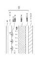
以下、本発明の実施の形態を実施例に基づいて説明する。図1は、本発明の一実施例としての熱処理装置の構成を示す説明図である。この熱処理装置は、基板Wを載置するための円形のプレート310と、プレート310の下方に設けられた熱媒体槽320と、熱媒体槽320の下面に設けられたリング状のヒータ330とを備えている。熱媒体槽320内には温度センサ334が挿入されており、この温度センサ334とヒータ330は、ヒータ制御部332に接続されている。なお、ヒータ330としては種々の加熱器を用いることができる。例えば、金属製やセラミック製の部材に電熱線をらせん状に配置して埋め込んだものを、用いることが可能であり、また、赤外線や熱風を利用した加熱器を用いることも可能である。
【0016】
プレート310の下面側と熱媒体槽320との間には空間が形成されており、プレート310と熱媒体槽320とは組み合わされて密閉容器300を構成している。密閉容器300の中には熱媒体TMが気液界面を有する状態で蓄えられている。密閉容器300の接合部には図示しない断熱材が配置されており、プレート310と熱媒体槽320とは互いに断熱されている。
【0017】
後述するように、この熱処理装置では、熱媒体TMの気体がプレート310の下面で凝結(液化)する際の潜熱を利用してプレート310および基板Wを加熱する。なお、プレート310としては、基板Wを均一に加熱するため、基板Wの直径よりも大きく、また、熱容量が大きいものが好ましい。
【0018】
密閉容器300の周縁部には、第1の気体排出ノズル301(図1では密閉容器300の左側に設置)と第2の気体排出ノズル302(図1では密閉容器300の右側に設置)とが設けられている。また、密閉容器300の中央下部には、液体流入ノズル303が設けられている。気体排出ノズル301,302は、密閉容器300内の上部空間の気相部分に設置されており、液体流入ノズル303は、下部空間の液相部分に設置されている。
【0019】
第1の気体排出ノズル301と液体流入ノズル303とは、循環管路400で互いに接続されている。循環管路400の途中には、調整弁402と、コンプレッサ404と、熱交換器406と、流量制御部408とが設けられている。流量制御部408には、熱媒体TMを外部に排出したり、外部から熱媒体TMを供給したりするためのノズル410が接続されている。このノズル410には、流量制御部408によって制御される開閉弁412が設けられている。
【0020】
コンプレッサ404は、密閉容器300の内部から熱媒体TMの気体を吸引するとともに断熱圧縮して液化し、熱交換器406は、液化した熱媒体TMの熱を除去する。熱交換器406で冷却された熱媒体TMは、流量制御部408により、再び熱媒体槽320に供給される。このようにして熱媒体TMを循環させることができる。
【0021】
流量制御部408は、熱媒体TMを循環管路400内で循環させる際に、循環管路400を循環する熱媒体TMの流量を調整する機能を有している。流量制御部408は、例えば、流量制御弁とそのコントローラとで構成される。流量制御部408は、さらに、ノズル410に設けられた開閉弁412を制御することによって、密閉容器300内に熱媒体TMを補給したり、密閉容器300から外部に熱媒体TMを排出したりする機能も有している。
【0022】
なお、循環管路400は、プレート310上の基板Wを加熱する際に、コンプレッサ404を用いて密閉容器300から熱媒体TMの気体を吸引して密閉容器300内の圧力を調整するために使用される。また、基板Wを冷却する際に、熱媒体TMを循環させながら熱交換器406で熱媒体TMを冷却することによってプレート310を冷却するために使用される。
【0023】
密閉容器300の第2の気体排出ノズル302には調整弁502が設けられており、この調整弁502の手前に設けられた圧力測定ポート504には、圧力センサ510が設置されている。なお、第1と第2の気体排出ノズル301,302にそれぞれ設けられた調整弁402,502は、圧力制御部520によって制御される。圧力制御部520は、圧力センサ510で測定される圧力が所望の値になるように、調整弁402,502の開度を調整するとともに、前述のコンプレッサ404の動作を制御する。なお、調整弁502は、密閉容器300内部が高圧状態となった際の安全弁としての機能も有している。
【0024】
基板Wの加熱処理は、密閉容器300内において、熱媒体TMの気体がプレート310の下面で凝結(液化)する際の潜熱を利用して行われる。すなわち、熱媒体TMをヒータ330で加熱すると熱媒体TMが蒸発(気化)し、この気体がプレート310の下面に達する。この気体は、プレート310の下面で潜熱を奪われて凝結するが、この際、熱媒体TMの液体と気体とは同じ温度に保たれる。凝結した熱媒体TMは、密閉容器300内の液相部に滴下してくるので、この熱媒体TMを再びヒータ330で加熱することによって、気化させることができる。
【0025】
なお、一般に、物質の沸点は圧力に依存する。従って、密閉容器300内における熱媒体TMの気体の温度は、圧力制御部520によって密閉容器300内の圧力を調整することによって変更することが可能である。
【0026】
熱処理装置に用いられる熱媒体TMとしては、密閉容器300の耐圧性が低くても済むように、ほぼ1気圧で所望の温度以上の沸点が得られるものが好ましい。例えば、プレート310の温度を常温から180℃程度までの範囲に設定することを想定する場合には、1気圧での沸点が使用温度範囲の上限の180℃付近である熱媒体TMを使用することが好ましい。
【0027】
図2は、本実施例における熱処理装置に適した熱媒体の一例を示す説明図である。図2の右欄は、左蘭の各物質の1気圧でのおおよその沸点を示している。本熱処理装置に用いることができる熱媒体は、図2に示す物質に限られず、種々の物質を用いることができる。なお、熱媒体としては、沸点温度が適当であることに加え、単位体積あたりの熱容量が大きく、装置に対する腐食作用がないものが好ましい。
【0028】
なお、圧力制御部520を用いて、密閉容器300内の圧力を1気圧以下に調整すれば、プレート310の下面で熱媒体TMが液化する温度(すなわちプレート310の温度)を、1気圧における沸点以下の所望の温度に設定することが可能である。熱媒体TMの圧力と沸点との関係は、圧力制御部520の図示しないメモリに予め格納されており、密閉容器300内部の圧力は、この関係に基づいて調整される。
【0029】
以上の説明から分かるように、本実施例の圧力センサ510、調整弁402,502、コンプレッサ404、熱交換器406、流量制御部408、圧力制御部520が本発明における圧力調整部に相当する。また、本実施例の循環管路が本発明における液化循環部に相当する。
【0030】
C.熱処理装置の動作:
図3は、熱処理装置のプレート310に載置された基板Wの加熱処理の手順を示すフローチャートである。ステップS1では、ヒータ330をONして熱媒体槽320に蓄えられた熱媒体TMの加熱を開始する。熱媒体TMを加熱する際には、熱媒体槽320内における熱媒体TMの温度差をできるだけ小さくすることが好ましい。このため、例えば、熱媒体槽320に撹拌機構を設けて熱媒体槽320内の熱媒体TMを撹拌するようにしてもよい。
【0031】
ステップS2では、熱媒体TMの加熱を継続した状態で、圧力制御部520が密閉容器300内部の圧力値を所定の値に保つように調整弁402,502やコンプレッサ404を制御する。熱媒体TMの沸点は圧力に依存しており、密閉容器300内部の圧力は、熱媒体TMが所望の沸点となる値に調整される。
【0032】
ステップS3においては、熱媒体TMが沸点に到達すると、プレート310が熱媒体TMの沸点付近まで加熱される。図4は、プレート310が加熱される過程を示す説明図である。熱媒体TMが所望の圧力Pで沸点Tに達すると、熱媒体TMは蒸発(気化)する。プレート310の温度が熱媒体TMの沸点Tに達していないときには、気化した熱媒体TMはプレート310の下面で液化する。このとき、プレート310には、熱媒体TMが液化する際に発生する潜熱Qが与えられる。例えば、熱媒体TMが水であるときには、1気圧(沸点100℃)での潜熱Qはおよそ539cal/g(2256.9J/g)である。プレート310が潜熱Qにより加熱され熱媒体TMの沸点Tに達すると、プレート下面での熱媒体TMの液化は止まり、温度Tで一定に保たれる。このようにしてプレート310が加熱されることにより、プレート310に載置された基板Wが加熱される。
【0033】
図5は、プレート310に載置された基板Wの冷却処理の手順を示すフローチャートである。ステップS4では、ヒータ330をOFFして熱媒体槽320に蓄えられた熱媒体TMの加熱を停止する。
【0034】
ステップS5では、循環管路400の各機器を利用して密閉容器300内部を減圧し、これによってプレート310を冷却する。図6は、プレート310が冷却される過程を示す説明図である。密閉容器300内部を減圧して圧力P’とすると熱媒体TMの沸点T’が低下し、この結果、プレート310の下面で液化している熱媒体TMが蒸発(気化)する。このように熱媒体TMが気化するときには、潜熱(気化熱)Q’が必要となり、この熱量Q’は加熱されたプレート310から与えられる。したがって、プレート310の下面における熱媒体TMの気化(蒸発)に伴って、プレート310から潜熱(気化熱)Q’が奪われ、プレート310は冷却される。このようにして基板Wは、プレート310によって冷却される。なお、基板Wを冷却する際には、密閉容器300内を液体で満たし、ポンプなどにより液体を循環させるようにしてもよい。
【0035】
以上、説明したように、本発明による熱処理装置では、プレート310は、熱媒体TMがプレート310の下面で液化するときの潜熱により加熱され、また、プレート310の下面で液化した熱媒体TMが気化するときの潜熱(気化熱)により冷却される。この熱処理装置を用いる場合には、ヒータ330の温度分布による影響を受けずに、プレート310をほぼ均一に加熱することがきるので、プレート310に載置した基板Wの温度分布の「むら」を防止し、ほぼ均一な処理を行うことが可能となる。
【0036】
なお、この発明は上記の実施例や実施形態に限られるものではなく、その要旨を逸脱しない範囲において種々の態様において実施することが可能であり、例えば次のような変形も可能である。
【0037】
上記実施例においては、熱交換器406は、コンプレッサ404により圧縮、液化された熱媒体TMを冷却するのみであるが、熱交換器406を加熱できるようにしてもよい。すなわち、熱交換器406にヒータなどの加熱装置を取り付けてもよい。こうすれば、熱交換器406において、熱媒体TMを所望の温度に設定することができ、予め加熱した熱媒体TMを熱媒体槽320に供給することにより熱媒体TMの加熱時間を短縮することができる。なお、熱媒体TMを循環させる管路に、加熱装置を取り付けることも可能である。この場合には、熱媒体槽320の下面にヒータ330を省略することもできる。
【図面の簡単な説明】
【図1】本発明の一実施例としての熱処理装置の構成を示す説明図。
【図2】本実施例における熱処理装置に適した熱媒体の一例を示す説明図。
【図3】熱処理装置のプレート310に載置された基板Wの加熱処理の手順を示すフローチャート。
【図4】プレート310が加熱される過程を示す説明図。
【図5】プレート310に載置された基板Wの冷却処理の手順を示すフローチャート。
【図6】プレート310が冷却される過程を示す説明図。
【図7】従来の加熱ユニットの断面を示す説明図。
【符号の説明】
22…プレート
24…ヒータ
300…密閉容器
301,302…気体排出ノズル
303…液体流入ノズル
310…プレート
320…熱媒体槽
330…ヒータ
332…ヒータ制御部
334…温度センサ
400…循環管路
402,502…調整弁
404…コンプレッサ
406…熱交換器
408…流量制御部
410…ノズル
412…開閉弁
504…圧力測定ポート
510…圧力センサ
520…圧力制御部
TM…熱媒体
W…基板[0001]
BACKGROUND OF THE INVENTION
The present invention relates to a technique for heat-treating a substrate.
[0002]
[Prior art]
In a substrate processing apparatus for processing a substrate such as a semiconductor substrate, a glass substrate for a photomask, a glass substrate for a liquid crystal display device, a substrate for an optical disk, etc., a plurality of processing units for performing various processes are combined. Yes. For example, a semiconductor substrate processing apparatus used in a step of applying a photoresist to a semiconductor substrate is composed of a plurality of processing units such as a resist coating unit, a heating unit, and a cooling unit. The heating unit and the cooling unit are heat treatment apparatuses that perform heat treatment of the substrate.
[0003]
The heating unit is mainly used for heating and curing the photoresist applied on the upper surface of the substrate. In such a heating unit, in order to remove the gas (air) contained in the photoresist applied on the substrate, the substrate is usually heated from the lower surface side (the surface opposite to the photoresist coating surface).
[0004]
FIG. 7 is an explanatory view showing a cross section of a conventional heating unit. In the heating unit of FIG. 7, the
[0005]
[Problems to be solved by the invention]
However, in the
[0006]
The present invention has been made to solve the above-described problems in the prior art, and an object thereof is to provide a technique capable of making the in-plane temperature distribution of the plate of the heat treatment apparatus substantially uniform.
[0007]
[Means for solving the problems and their functions and effects]
In order to solve at least a part of the above problems, a heat treatment apparatus of the present invention is a heat treatment apparatusfor heat treating a substrate,
A plate for mounting the substrate;
Forming a space with the plate on the lower surface side of the plate, and a heat medium tank for storing a heat medium in the space;
A heater for heating the heat medium stored in the heat medium tank;
Including a circulation line connected to the heat medium tank, and a circulation system for circulating the heat medium;
With
The circulatory system is
A heat medium amount adjusting unit for adjusting the amount of the heat medium in the heat medium tank;
A heat exchanger for cooling the heat medium passing through the circulation line;
With
When the substrate is heated,
The heater heats the heat medium in a state where the heat medium has a gas-liquid interface in the space, and as a result, the plate is generated when the gas of the heat medium is liquefied on the lower surface of the plate. Heated by latent heat,
When the substrate is cooled,
The heat medium amount adjusting unit replenishes the heat medium tank with the heat medium to fill the space with the heat medium,
The circulation system supplies the heat medium cooled by the heat exchanger to the heat medium tank by circulating the heat medium in a state where the space is filled with the heat medium. .
[0008]
The plate in the heat treatment apparatus is heated by the latent heat generated when the vaporized heat medium is liquefied on the lower surface of the plate. Therefore, the in-plane temperature distribution of the plate can be made substantially uniform without being affected by the temperature distribution of the heater, and “unevenness” of the temperature distribution of the substrate can be reduced.
[0009]
Furthermore, in the heat treatment apparatus,
It is preferable to provide a pressure adjusting unit for adjusting the pressure in the space.
[0010]
In this case, the pressure in the space formed by the plate and the heat medium tank can be arbitrarily adjusted by the pressure adjusting unit, so that it is easy to adjust the temperature of the plate determined by the boiling point of the heat medium. Further, if the pressure inside the space is gradually reduced by the pressure adjusting unit, the latent heat (vaporization heat) is taken from the plate when the heat medium liquefied on the lower surface of the plate is vaporized, so that the plate can be cooled.
[0011]
In the heat treatment apparatus,
The pressure adjusting unit is
A pressure sensor for detecting the pressure in the space;
A regulating valve for discharging gas from the space to the outside;
A pressure control unit that adjusts the pressure in the space by controlling the adjustment valve based on a detection value of the pressure sensor;
You may make it provide.
[0012]
In the heat treatment apparatus,
The pressure adjusting unit is
While sucking the gas of the heat medium from the space and liquefying the gas,
The circulation system may return the liquefied heat medium to the heat medium tank .
[0015]
DETAILED DESCRIPTION OF THE INVENTION
A. Device configuration:
Hereinafter, embodiments of the present invention will be described based on examples. FIG. 1 is an explanatory diagram showing a configuration of a heat treatment apparatus as an embodiment of the present invention. This heat treatment apparatus includes a
[0016]
A space is formed between the lower surface side of the
[0017]
As will be described later, in this heat treatment apparatus, the
[0018]
A first gas discharge nozzle 301 (installed on the left side of the sealed
[0019]
The first
[0020]
The
[0021]
The flow
[0022]
The
[0023]
The second
[0024]
The heat treatment of the substrate W is performed using latent heat when the gas of the heat medium TM condenses (liquefies) on the lower surface of the
[0025]
In general, the boiling point of a substance depends on pressure. Therefore, the temperature of the gas of the heat medium TM in the sealed
[0026]
As the heat medium TM used in the heat treatment apparatus, a heat medium having a boiling point equal to or higher than a desired temperature at approximately 1 atm is preferable so that the pressure resistance of the sealed
[0027]
FIG. 2 is an explanatory diagram showing an example of a heat medium suitable for the heat treatment apparatus in the present embodiment. The right column of FIG. 2 shows the approximate boiling point of each substance in the left orchid at 1 atm. The heat medium that can be used in the heat treatment apparatus is not limited to the substance shown in FIG. 2, and various substances can be used. In addition to the appropriate boiling point temperature, the heat medium preferably has a large heat capacity per unit volume and no corrosive action on the apparatus.
[0028]
If the pressure in the sealed
[0029]
As can be seen from the above description, the
[0030]
C. Operation of heat treatment equipment:
FIG. 3 is a flowchart showing the procedure of the heat treatment of the substrate W placed on the
[0031]
In step S2, the
[0032]
In step S3, when the heat medium TM reaches the boiling point, the
[0033]
FIG. 5 is a flowchart showing the procedure of the cooling process for the substrate W placed on the
[0034]
In step S5, the inside of the sealed
[0035]
As described above, in the heat treatment apparatus according to the present invention, the
[0036]
The present invention is not limited to the above-described examples and embodiments, and can be implemented in various modes without departing from the gist thereof. For example, the following modifications are possible.
[0037]
In the above embodiment, the
[Brief description of the drawings]
FIG. 1 is an explanatory diagram showing a configuration of a heat treatment apparatus as one embodiment of the present invention.
FIG. 2 is an explanatory diagram showing an example of a heat medium suitable for the heat treatment apparatus in the present embodiment.
FIG. 3 is a flowchart showing a heat treatment procedure for a substrate W placed on a
FIG. 4 is an explanatory diagram showing a process in which a
FIG. 5 is a flowchart showing a procedure for cooling a substrate W placed on a
FIG. 6 is an explanatory view showing a process in which a
FIG. 7 is an explanatory view showing a cross section of a conventional heating unit.
[Explanation of symbols]
22 ...
Claims (4)
Translated fromJapanese前記基板を載置するためのプレートと、 A plate for mounting the substrate;
前記プレートの下面側において前記プレートとの間で空間を形成し、前記空間内に熱媒体を蓄えるための熱媒体槽と、 Forming a space between the plate on the lower surface side of the plate, and a heat medium tank for storing a heat medium in the space;
前記熱媒体槽に蓄えられる前記熱媒体を加熱するためのヒータと、 A heater for heating the heat medium stored in the heat medium tank;
前記熱媒体槽に接続された循環管路を含み、前記熱媒体を循環させるための循環系と、 Including a circulation line connected to the heat medium tank, and a circulation system for circulating the heat medium;
を備え、With
前記循環系は、 The circulatory system is
前記熱媒体槽内の前記熱媒体の量を調整するための熱媒体量調整部と、 A heat medium amount adjusting unit for adjusting the amount of the heat medium in the heat medium tank;
前記循環管路を通る前記熱媒体を冷却するための熱交換器と、 A heat exchanger for cooling the heat medium passing through the circulation line;
を備え、With
前記基板が加熱される際には、 When the substrate is heated,
前記ヒータは、前記空間内で前記熱媒体が気液界面を有する状態で前記熱媒体を加熱し、この結果、前記プレートは、前記熱媒体の気体が前記プレートの下面で液化する際に発生する潜熱により加熱され、 The heater heats the heat medium in a state where the heat medium has a gas-liquid interface in the space, and as a result, the plate is generated when the gas of the heat medium is liquefied on the lower surface of the plate. Heated by latent heat,
前記基板が冷却される際には、 When the substrate is cooled,
前記熱媒体量調整部は、前記熱媒体槽に前記熱媒体を補給して前記空間を熱媒体で満たし、 The heat medium amount adjusting unit replenishes the heat medium tank with the heat medium to fill the space with the heat medium,
前記循環系は、前記空間が前記熱媒体で満たされた状態で前記熱媒体を循環させることによって、前記熱媒体槽に前記熱交換器で冷却された前記熱媒体を供給することを特徴とする熱処理装置。 The circulation system supplies the heat medium cooled by the heat exchanger to the heat medium tank by circulating the heat medium in a state where the space is filled with the heat medium. Heat treatment equipment.
前記空間の圧力を調整するための圧力調整部を備える、熱処理装置。The heat treatment apparatus according to claim 1, further comprising:
The heat processing apparatus provided with the pressure adjustment part for adjusting the pressure of the said space.
前記圧力調整部は、
前記空間内の圧力を検出するための圧力センサと、
前記空間から気体を外部に排出するための調整弁と、
前記圧力センサの検出値に基づいて前記調整弁を制御することによって前記空間内の圧力を調整する圧力制御部と、
を備える、熱処理装置。The heat treatment apparatus according to claim 2,
The pressure adjusting unit is
A pressure sensor for detecting the pressure in the space;
A regulating valve for discharging gas from the space to the outside;
A pressure control unit that adjusts the pressure in the space by controlling the adjustment valve based on a detection value of the pressure sensor;
A heat treatment apparatus comprising:
前記圧力調整部は、
前記空間から前記熱媒体の気体を吸引するとともに前記気体を液化し、
前記循環系は、液化した前記熱媒体を前記熱媒体槽に帰還させる、熱処理装置。The heat treatment apparatus according to claim 2 or 3,
The pressure adjusting unit is
While sucking the gas of the heat medium from the space and liquefying the gas,
The circulation system is a heat treatment apparatusthat returns the liquefied heat medium to the heat medium tank .
Priority Applications (1)
| Application Number | Priority Date | Filing Date | Title |
|---|---|---|---|
| JP10212398AJP3623653B2 (en) | 1998-03-30 | 1998-03-30 | Heat treatment equipment |
Applications Claiming Priority (1)
| Application Number | Priority Date | Filing Date | Title |
|---|---|---|---|
| JP10212398AJP3623653B2 (en) | 1998-03-30 | 1998-03-30 | Heat treatment equipment |
Publications (2)
| Publication Number | Publication Date |
|---|---|
| JPH11283919A JPH11283919A (en) | 1999-10-15 |
| JP3623653B2true JP3623653B2 (en) | 2005-02-23 |
Family
ID=14319025
Family Applications (1)
| Application Number | Title | Priority Date | Filing Date |
|---|---|---|---|
| JP10212398AExpired - Fee RelatedJP3623653B2 (en) | 1998-03-30 | 1998-03-30 | Heat treatment equipment |
Country Status (1)
| Country | Link |
|---|---|
| JP (1) | JP3623653B2 (en) |
Families Citing this family (4)
| Publication number | Priority date | Publication date | Assignee | Title |
|---|---|---|---|---|
| US20080145038A1 (en)* | 2006-12-15 | 2008-06-19 | Applied Materials, Inc. | Method and apparatus for heating a substrate |
| NL2003258A1 (en) | 2008-08-08 | 2010-02-09 | Asml Netherlands Bv | Lithographic apparatus and device manufacturing method. |
| JP5394730B2 (en)* | 2008-12-26 | 2014-01-22 | 東京エレクトロン株式会社 | Annealing apparatus and annealing method |
| WO2012042664A1 (en)* | 2010-10-01 | 2012-04-05 | 東芝三菱電機産業システム株式会社 | Soaking apparatus |
- 1998
- 1998-03-30JPJP10212398Apatent/JP3623653B2/ennot_activeExpired - Fee Related
Also Published As
| Publication number | Publication date |
|---|---|
| JPH11283919A (en) | 1999-10-15 |
Similar Documents
| Publication | Publication Date | Title |
|---|---|---|
| JP4815295B2 (en) | Plasma processing equipment | |
| US5892207A (en) | Heating and cooling apparatus for reaction chamber | |
| TW201131690A (en) | Temperature control system and temperature control method for substrate mounting table | |
| JP3607927B2 (en) | Steam generator | |
| EP0817989B1 (en) | Method and apparatus for supplying liquid cryogen | |
| TW201501811A (en) | Liquid treatment apparatus, liquid treatment method and storage medium | |
| JP3623653B2 (en) | Heat treatment equipment | |
| TW201448103A (en) | Plasma processing apparatus and plasma processing method | |
| KR101713112B1 (en) | Deposition material supply apparatus which can continuously charged | |
| KR100351731B1 (en) | Constant temperature-humidity oven | |
| KR100634654B1 (en) | ESR chamber cooling system and treatment | |
| JPS61199857A (en) | Apparatus for generating dry cooling gas stream | |
| JPH1047775A (en) | Hot water heater having auxiliary heater for pre-heating water flowed into water storing tank | |
| JP2008182204A (en) | Method and apparatus for heating a substrate | |
| TWI697083B (en) | Method and apparatus for using supercritical fluids in semiconductor applications | |
| JP3425826B2 (en) | Fluid supply device for substrate processing | |
| JP3443614B2 (en) | Evaporative cooling device | |
| JP3979764B2 (en) | Substrate heat treatment equipment | |
| JPH07226371A (en) | Substrate cooling device | |
| CN114746257B (en) | Apparatus and method for treating molded articles made of plastic with vapors of treatment liquid | |
| JP3518979B2 (en) | Substrate processing equipment | |
| JP2843307B2 (en) | Ozone concentration apparatus and ozone concentration method | |
| JP2008182205A (en) | Method and apparatus for heating a substrate | |
| KR100574276B1 (en) | Phase change liquid crystal injection device | |
| JPH0574698A (en) | Resist coating device |
Legal Events
| Date | Code | Title | Description |
|---|---|---|---|
| A977 | Report on retrieval | Effective date:20040802 Free format text:JAPANESE INTERMEDIATE CODE: A971007 | |
| A131 | Notification of reasons for refusal | Effective date:20040824 Free format text:JAPANESE INTERMEDIATE CODE: A131 | |
| A521 | Written amendment | Effective date:20041021 Free format text:JAPANESE INTERMEDIATE CODE: A523 | |
| TRDD | Decision of grant or rejection written | ||
| A01 | Written decision to grant a patent or to grant a registration (utility model) | Free format text:JAPANESE INTERMEDIATE CODE: A01 Effective date:20041124 | |
| A61 | First payment of annual fees (during grant procedure) | Effective date:20041125 Free format text:JAPANESE INTERMEDIATE CODE: A61 | |
| R150 | Certificate of patent (=grant) or registration of utility model | Free format text:JAPANESE INTERMEDIATE CODE: R150 | |
| FPAY | Renewal fee payment (prs date is renewal date of database) | Free format text:PAYMENT UNTIL: 20071203 Year of fee payment:3 | |
| FPAY | Renewal fee payment (prs date is renewal date of database) | Free format text:PAYMENT UNTIL: 20081203 Year of fee payment:4 | |
| FPAY | Renewal fee payment (prs date is renewal date of database) | Year of fee payment:4 Free format text:PAYMENT UNTIL: 20081203 | |
| FPAY | Renewal fee payment (prs date is renewal date of database) | Free format text:PAYMENT UNTIL: 20091203 Year of fee payment:5 | |
| FPAY | Renewal fee payment (prs date is renewal date of database) | Year of fee payment:5 Free format text:PAYMENT UNTIL: 20091203 | |
| FPAY | Renewal fee payment (prs date is renewal date of database) | Free format text:PAYMENT UNTIL: 20091203 Year of fee payment:5 | |
| LAPS | Cancellation because of no payment of annual fees |