JP3622730B2 - Sphygmomanometer arm band - Google Patents
Sphygmomanometer arm bandDownload PDFInfo
- Publication number
- JP3622730B2 JP3622730B2JP2002026424AJP2002026424AJP3622730B2JP 3622730 B2JP3622730 B2JP 3622730B2JP 2002026424 AJP2002026424 AJP 2002026424AJP 2002026424 AJP2002026424 AJP 2002026424AJP 3622730 B2JP3622730 B2JP 3622730B2
- Authority
- JP
- Japan
- Prior art keywords
- arm
- elastic plate
- rigidity
- sphygmomanometer
- hole
- Prior art date
- Legal status (The legal status is an assumption and is not a legal conclusion. Google has not performed a legal analysis and makes no representation as to the accuracy of the status listed.)
- Expired - Lifetime
Links
- 239000000463materialSubstances0.000claimsdescription6
- 230000036772blood pressureEffects0.000claimsdescription2
- 230000015572biosynthetic processEffects0.000claims1
- 230000000694effectsEffects0.000description3
- 239000004743PolypropyleneSubstances0.000description2
- 239000004744fabricSubstances0.000description2
- 238000013459approachMethods0.000description1
- 238000000465mouldingMethods0.000description1
- -1polypropylenePolymers0.000description1
- 229920001155polypropylenePolymers0.000description1
- 239000011347resinSubstances0.000description1
- 229920005989resinPolymers0.000description1
- 210000000707wristAnatomy0.000description1
Images


Classifications
- A—HUMAN NECESSITIES
- A61—MEDICAL OR VETERINARY SCIENCE; HYGIENE
- A61B—DIAGNOSIS; SURGERY; IDENTIFICATION
- A61B5/00—Measuring for diagnostic purposes; Identification of persons
- A61B5/02—Detecting, measuring or recording for evaluating the cardiovascular system, e.g. pulse, heart rate, blood pressure or blood flow
- A61B5/021—Measuring pressure in heart or blood vessels
- A61B5/022—Measuring pressure in heart or blood vessels by applying pressure to close blood vessels, e.g. against the skin; Ophthalmodynamometers
- A61B5/02233—Occluders specially adapted therefor
Landscapes
- Health & Medical Sciences (AREA)
- Life Sciences & Earth Sciences (AREA)
- Cardiology (AREA)
- Vascular Medicine (AREA)
- Engineering & Computer Science (AREA)
- Medical Informatics (AREA)
- Physics & Mathematics (AREA)
- Ophthalmology & Optometry (AREA)
- Biophysics (AREA)
- Pathology (AREA)
- Dentistry (AREA)
- Biomedical Technology (AREA)
- Heart & Thoracic Surgery (AREA)
- Physiology (AREA)
- Molecular Biology (AREA)
- Surgery (AREA)
- Animal Behavior & Ethology (AREA)
- General Health & Medical Sciences (AREA)
- Public Health (AREA)
- Veterinary Medicine (AREA)
- Measuring Pulse, Heart Rate, Blood Pressure Or Blood Flow (AREA)
Description
Translated fromJapanese【0001】
【発明の属する技術分野】
本発明は、血圧計の腕帯に関し、詳細には空気袋の外側に配置されて自身の環状形態を保持するための弾性板に特徴がある腕帯に関する。
【0002】
【従来の技術】
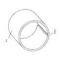
血圧計の腕帯は一般に、図6(斜視図)及び図7(断面図)に示すように、布袋30内に空気袋31と弾性板32が配置されたもので、空気袋31にはチューブ33が接続され、布袋30の外側には面ファスナ34が取り付けられている。弾性体32は、空気袋31の外側に配置され、自身の弾性力により腕帯を環状形態に保持するためのものであり、図8に示すように、均一な肉厚であり、一部が不連続部分32aとなる真円形の断面形状を持つものである。
【0003】
【発明が解決しようとする課題】
しかしながら、図8のような弾性板32では、
▲1▼弾性板32を腕に装着すると、その弾性力により弾性板の不連続部分32aのエッジが腕に食い込み、特に腕の太い使用者に痛みを与えることがある。
▲2▼弾性板32が均一な肉厚で、かつ断面形状が真円形であるために、腕の径の太い人や細い人に対応した変形ができず、腕にフィットしにくい。
【0004】
上記の問題点に対し、特開昭61−238229号公報では図9に示すような弾性板42が提案されている。この弾性板42は、両端部から中央部に向けて腕周方向に肉厚が徐々に厚くなり、それによって弾性板42の剛性が徐々に大きくなるように形成されており、中央部で肉厚及び剛性が最大となっている。
【0005】
しかし、この弾性板42でも、上記の問題点に対しては改善が見られるものの、例えば上腕部において肘付近の腕の径は細いが肩に近づくにつれて腕の径が太くなっているなど、腕の部位における径の太さの変化が大きい、いわゆる傾斜の大きい腕に対しては、弾性板42は腕の径の太い部分にはフィットするが細い部分では弾性板42と腕との間に隙間が生じてしまう。このように、弾性板42は腕の形状に対応する変形が十分でない。
【0006】
本発明は、このような従来技術の課題を解決することを目的としてなされたもので、腕の形状の多様性、特に傾斜の大きい腕に対してもフィット性に優れた血圧計の腕帯を提供するものである。
【0007】
【課題を解決するための手段】
前記目的を達成するために、本発明の血圧計の腕帯は、空気袋と、この空気袋の外側に配置されて自身の環状形態を保持するための弾性板とを内部に有するものにおいて、弾性板は、装着された腕の径の細い側に対応する部分の剛性を高く、腕の径の太い側に対応する部分の剛性を低くしたことを特徴とする。
【0008】
この弾性板では、腕への装着時に剛性の高い部分は腕をしっかりと締め付け、剛性の低い部分は腕の形状に倣うことになるため、腕の形状に適合して装着できる。また、弾性板は装着された腕の径の細い方に相当する側に対応する部分の剛性を高く、腕の径の太い方に相当する側に対応する部分の剛性を低くすることで、特に傾斜の大きい腕に適合して装着できる。
【0009】
さらに、弾性板は環状の腕周方向においても剛性を不均一としても構わない。こうすれば、弾性板がねじれやすくなり、さらに多様な腕の形状に適合できる。
【0010】
また、弾性板は腕への装着時に内側となる端部の剛性を低くすることもできる。こうすれば、腕への装着時に腕に当接した端部は、腕の形状に倣うことになるため、腕への痛みを緩和できる。
【0011】
この弾性板では、肉厚を薄くすることで剛性の低い部分を形成してもよい。これにより、剛性の異なる領域を容易に形成することができる。また、弾性板は形状の異なる少なくとも2個の部材を接合し、少なくとも2個の部材が重ならない領域を設けることで剛性の低い部分を形成しても構わない。これにより、剛性の違いをより多くの条件で設定することが可能となる。
【0012】
さらに、弾性板は素材に孔または穴加工を施すことで剛性の低い部分を形成しても構わない。孔(または穴)の下降位置、密度、孔(または穴)径などの設定により、剛性の違いをより適切に設定することが可能となる。
【0013】
【発明の実施の形態】
以下、図面を参照して本発明の実施形態を説明する。ただし、本発明における血圧計の腕帯はその弾性板に特徴があり、弾性板以外の腕帯の構造は図6に示す従来のものでもよい。したがって、以下では弾性板を中心に説明する。この弾性板に関する作用は、その弾性板を備える腕帯も備えている。
【0014】
(第1実施形態)
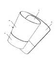
本発明の第1実施形態による血圧計の腕帯に備えられる弾性板の斜視図を図1に、またその展開図を図2(a)に示す。また、図2(a)において、A−A’断面で図中右方から見た断面図を図2(b)に示す。この弾性板1は、PP(ポリプロピレン)などの樹脂を材質としており、薄肉部分2と厚肉部分3の2種類の肉厚が異なる領域を備えている。弾性板1を腕に装着する際には、一端部4が他端部5の内側にくるように巻き付ける。弾性板1を腕に装着した状態における腕軸方向に着目すると、筒状となった弾性板1の一端が薄肉部分2に、他端が厚肉部分3になっている。厚肉部分3は剛性が高く、腕に対してしっかりと巻き付き、また薄肉部分2は剛性が低く、厚肉部分3に対して腕の形状に倣って変形しやすい。これにより、腕の径の細い部分に厚肉部分3が、太い部分に薄肉部分2が対応するように弾性板1の向きを合わせ、厚肉部分3と腕の径の細い部分との間に隙間ができないように弾性板1を巻き付けると、腕の径の太い部分には薄肉部分2が変形して密着するため、腕全体に隙間なく装着することができる。
【0015】
また、この実施形態では弾性板1の剛性を高低2段階で形成したが、より細かく剛性を設定したり、図2(c)に示した断面図のように肉厚を腕軸方向の一端側から他端側に向かって徐変することなどにより剛性を連続的に変化させたりしても構わない。
【0016】
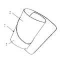
(第2実施形態)
本発明の第2実施形態による血圧計の腕帯に備えられる弾性板の斜視図を図3に、その展開図を図4(a)に示す。また、図4(a)において、B−B’断面で図中右方から見た断面図を図4(b)に示す。この弾性板11は、薄肉部分12と厚肉部分13の2種類の肉厚が異なる領域を備えている。弾性板11を上腕に装着する際には、この薄肉部分12が肩側にくるように向け、一端部14が他端部15の内側にくるように上腕に巻き付ける。弾性板11を上腕に装着した状態における腕軸方向に着目すると、肩側に相当する部分が肘側よりも薄肉部分12に、肘側が厚肉部分13になっている。これにより、本発明の第1実施形態による血圧計の腕帯に備えられる弾性板1と同様に、肩側に比べて径が細い肘付近の腕に対して剛性の高い肉厚部分13を隙間ができないように巻き付けると、肘側に比べて径が太い肩側の腕には剛性の低い薄肉部分12が変形して密着することにより、傾斜の大きい腕の全体に対して隙間なく装着することができる。
【0017】
次に、腕周方向に着目すると、弾性体11に図示しない空気袋に接続されたチューブを挿通する孔16を設けた部分の両脇が、厚肉部分13の腕軸方向の幅を部分的に狭くした狭幅部分17、18となっている。この狭幅部分17、18では弾性板11の腕軸方向の剛性が低いので弾性板がねじれやすく、多様な傾斜度合いの腕に適合して、より高い密着性を確保して装着することができる。
【0018】
また、孔16付近は厚肉部分13の腕軸方向の幅を広くした幅広部分19としており、空気袋による腕への加圧の際の変形を低減するように剛性を高くしている。さらに、一端部14および他端部15については一端部14付近を薄肉部分12に、他端部15付近を厚肉部分13としている。これは、上腕に巻き付けた際、内側となって腕に当接する一端側15は剛性を低くして腕の形状に倣うことで腕への痛みを緩和させ、また他端側16は剛性を高くして腕への密着を確実にするためである。
【0019】
剛性が均一ではない弾性板を形成するには、例えば薄肉部分12と厚肉部分13とを一体成型により弾性板11を形成してもよいし、厚肉部分13の肉厚で形成した弾性板11の全体形状の部材から、薄肉部分12に相当する部分を切削加工して肉厚を薄くしてもよい。また、薄肉部分12の肉厚で形成した弾性板11の全体形状の部材に、厚肉部分13に相当する部分の形状の部材を接合することも可能である。その際、例えば全体形状の部材は剛性が低い材質を、厚肉部分13に相当する部分の形状の部材は剛性が高い材質を用いるというように、剛性が異なる材質を用いることも効果的である。
【0020】
また、展開図である図4に示した薄肉部分12と厚肉部分13の境界パターンは図示したものに限定されない。
【0021】
(第3実施形態)
本発明の第3実施形態による血圧計の腕帯に備えられる弾性板21の展開図を図5に示す。この弾性板21は、第2実施形態による弾性板11と同じ形態を実現するための他の形態であり、素材に孔加工(または穴加工)を施すことで腕軸方向および腕周方向の剛性を変化させている。すなわち、第2実施形態の弾性板11における薄肉部分12に相当する剛性を低くしたい部分22には孔加工(または穴加工)を施して、孔(または穴)24を複数設け、厚肉部分13に相当する剛性を高くしたい部分23には孔加工も穴加工も施していない。これにより、弾性板21の全体の肉厚は均一であるが、腕軸方向および腕周方向の剛性は均一ではなく、腕の形状に適合して変形するような所望の剛性分布となり、第2実施形態の弾性板11と同様に、腕の傾斜の大きさや形状が多様であっても、弾性板21は腕に密着して装着することができる。
【0022】
なお、孔または穴の加工位置、加工密度、孔径または穴径を任意に設定することで本発明の作用・効果はより効果的に実現できる。孔または穴の大きさも同じにする必要もなく、大小混在してもよい。図5では孔または穴の何れか一方の加工を施しているが、孔と穴とが混在する加工を施してもよい。したがって、孔または穴加工のパターンも、第2実施形態と同様に、図5に示したものに限定されない。
【0023】
【発明の効果】
以上のように、本発明の血圧計の腕帯によれば、腕の形状の多様性、特に傾斜の大きい腕に対しても密着して装着できる。
【図面の簡単な説明】
【図1】本発明の第1実施形態における弾性体の斜視図である。
【図2】本発明の第1実施形態における弾性体の展開図である。
【図3】本発明の第2実施形態における弾性体の斜視図である。
【図4】本発明の第2実施形態における弾性体の展開図である。
【図5】本発明の第3実施形態における弾性体の展開図である。
【図6】一般的な血圧計の腕帯の外観を示す斜視図である。
【図7】図6の腕帯の内部を示す断面図である。
【図8】従来の弾性板の斜視図である。
【図9】従来の弾性板の斜視図である。
【符号の簡単な説明】
1 弾性板
2 薄肉部分
3 厚肉部分
4、5 両端部
11 弾性板
12 薄肉部分
13 厚肉部分
17、18 狭幅部分
19 幅広部分
21 弾性板
22 剛性を低くしたい部分
23 剛性を高くしたい部分
24 孔(または穴)[0001]
BACKGROUND OF THE INVENTION
The present invention relates to an arm band of a sphygmomanometer, and more particularly, to an arm band characterized by an elastic plate that is disposed outside a bladder and holds its own annular form.
[0002]
[Prior art]
As shown in FIG. 6 (perspective view) and FIG. 7 (cross-sectional view), an armband of a sphygmomanometer generally has an
[0003]
[Problems to be solved by the invention]
However, in the
(1) When the
(2) Since the
[0004]
In response to the above problems, Japanese Patent Application Laid-Open No. 61-238229 proposes an
[0005]
However, even with the
[0006]
The present invention has been made for the purpose of solving such problems of the prior art, and an arm band of a sphygmomanometer excellent in fit even for a variety of arm shapes, particularly an arm with a large inclination. It is to provide.
[0007]
[Means for Solving the Problems]
In order to achieve the above-mentioned object, the armband of the sphygmomanometer according to the present invention has an air bag and an elastic plate disposed inside the air bag for holding its own annular shape inside. elastic plate,increases the rigidity of the portion corresponding to the narrow side of the diameter of the arm that is mounted,it characterized in that tolower the rigidity of the portion corresponding to the thick side of the diameter of the arm.
[0008]
With this elastic plate, when the arm is mounted, the portion with high rigidity firmly tightens the arm, and the portion with low rigidity follows the shape of the arm, so that it can be mounted according to the shape of the arm. In addition, the elastic plate has a high rigidity corresponding to the side corresponding to the thinner arm diameter, and a lower rigidity corresponding to the side corresponding to the thicker arm diameter. It can be worn to fit an arm with a large inclination.
[0009]
Further, the elastic plate may have non-uniform rigidity even in the annular arm circumferential direction. By doing so, the elastic plate is easily twisted, and can be adapted to various arm shapes.
[0010]
Further, the elastic plate can reduce the rigidity of the inner end portion when the elastic plate is attached to the arm. By so doing, the end that is in contact with the arm when worn on the arm follows the shape of the arm, so that the pain on the arm can be alleviated.
[0011]
In this elastic plate, a portion having low rigidity may be formed by reducing the thickness. Thereby, the area | region from which rigidity differs can be formed easily. The elastic plate may be formed with a portion having low rigidity by joining at least two members having different shapes and providing a region where at least two members do not overlap. Thereby, the difference in rigidity can be set under more conditions.
[0012]
Further, the elastic plate may be formed with a portion having low rigidity by subjecting the material to hole or hole processing. By setting the descending position, density, hole (or hole) diameter, etc. of the hole (or hole), it becomes possible to set the difference in rigidity more appropriately.
[0013]
DETAILED DESCRIPTION OF THE INVENTION
Hereinafter, embodiments of the present invention will be described with reference to the drawings. However, the arm band of the sphygmomanometer according to the present invention is characterized by its elastic plate, and the structure of the arm band other than the elastic plate may be the conventional one shown in FIG. Therefore, below, it demonstrates centering on an elastic board. The action relating to the elastic plate is also provided with an arm band provided with the elastic plate.
[0014]
(First embodiment)
FIG. 1 is a perspective view of an elastic plate provided in the arm band of the sphygmomanometer according to the first embodiment of the present invention, and FIG. Further, in FIG. 2 (a), a cross-sectional view taken along the line AA 'seen from the right side in the drawing is shown in FIG. 2 (b). The
[0015]
In this embodiment, the rigidity of the
[0016]
(Second Embodiment)
FIG. 3 is a perspective view of an elastic plate provided in an arm band of a sphygmomanometer according to the second embodiment of the present invention, and FIG. FIG. 4B is a cross-sectional view taken along the line BB ′ in FIG. The
[0017]
Next, paying attention to the arm circumferential direction, both sides of the portion where the
[0018]
Further, the vicinity of the hole 16 is a wide portion 19 in which the width of the
[0019]
In order to form an elastic plate whose rigidity is not uniform, for example, the
[0020]
Further, the boundary pattern between the
[0021]
(Third embodiment)
FIG. 5 shows a development view of the
[0022]
In addition, the effect | action and effect of this invention can be implement | achieved more effectively by setting the processing position of a hole or a hole, processing density, a hole diameter, or a hole diameter arbitrarily. The sizes of the holes or holes need not be the same, and may be mixed. In FIG. 5, either hole or hole processing is performed, but processing in which holes and holes are mixed may be performed. Accordingly, the hole or hole processing pattern is not limited to that shown in FIG. 5 as in the second embodiment.
[0023]
【The invention's effect】
As described above, according to the armband of the sphygmomanometer according to the present invention, it can be worn in close contact with a variety of arm shapes, particularly an arm with a large inclination.
[Brief description of the drawings]
FIG. 1 is a perspective view of an elastic body according to a first embodiment of the present invention.
FIG. 2 is a development view of an elastic body in the first embodiment of the present invention.
FIG. 3 is a perspective view of an elastic body according to a second embodiment of the present invention.
FIG. 4 is a development view of an elastic body according to a second embodiment of the present invention.
FIG. 5 is a development view of an elastic body according to a third embodiment of the present invention.
FIG. 6 is a perspective view showing an appearance of a wrist band of a general blood pressure monitor.
7 is a cross-sectional view showing the inside of the armband of FIG. 6. FIG.
FIG. 8 is a perspective view of a conventional elastic plate.
FIG. 9 is a perspective view of a conventional elastic plate.
[Brief description of symbols]
DESCRIPTION OF
Claims (6)
Translated fromJapanese前記弾性板は、装着された腕の径の細い側に対応する部分の剛性を高く、腕の径の太い側に対応する部分の剛性を低くしたことを特徴とする血圧計の腕帯。In the armband of a sphygmomanometer that has an air bag and an elastic plate that is arranged outside the air bag and holds its annular shape inside,
The elastic band of the sphygmomanometer, wherein the elastic plate has ahigh rigidity corresponding to the side of the arm having a small diameter and a low rigidity corresponding to the side of the arm having a large diameter .
Priority Applications (5)
| Application Number | Priority Date | Filing Date | Title |
|---|---|---|---|
| JP2002026424AJP3622730B2 (en) | 2002-02-04 | 2002-02-04 | Sphygmomanometer arm band |
| EP20030000087EP1332717B1 (en) | 2002-02-04 | 2003-01-08 | Cuff for blood pressure monitor |
| DE2003600023DE60300023T2 (en) | 2002-02-04 | 2003-01-08 | Cuff for a sphygmomanometer |
| CN 03102946CN1233296C (en) | 2002-02-04 | 2003-01-24 | Arm lacing for sphygmomanometer |
| US10/356,713US6997878B2 (en) | 2001-01-23 | 2003-02-03 | Cuff for blood pressure monitor |
Applications Claiming Priority (1)
| Application Number | Priority Date | Filing Date | Title |
|---|---|---|---|
| JP2002026424AJP3622730B2 (en) | 2002-02-04 | 2002-02-04 | Sphygmomanometer arm band |
Publications (2)
| Publication Number | Publication Date |
|---|---|
| JP2003225212A JP2003225212A (en) | 2003-08-12 |
| JP3622730B2true JP3622730B2 (en) | 2005-02-23 |
Family
ID=19192352
Family Applications (1)
| Application Number | Title | Priority Date | Filing Date |
|---|---|---|---|
| JP2002026424AExpired - LifetimeJP3622730B2 (en) | 2001-01-23 | 2002-02-04 | Sphygmomanometer arm band |
Country Status (4)
| Country | Link |
|---|---|
| EP (1) | EP1332717B1 (en) |
| JP (1) | JP3622730B2 (en) |
| CN (1) | CN1233296C (en) |
| DE (1) | DE60300023T2 (en) |
Families Citing this family (3)
| Publication number | Priority date | Publication date | Assignee | Title |
|---|---|---|---|---|
| JP4534583B2 (en)* | 2004-05-07 | 2010-09-01 | オムロンヘルスケア株式会社 | Sphygmomanometer cuff |
| JP2006255097A (en)* | 2005-03-16 | 2006-09-28 | Omron Healthcare Co Ltd | Cuff for sphygmomanometer and sphygmomanometer |
| DE102011052797B4 (en) | 2011-08-18 | 2013-05-29 | Polygreen Germany Gmbh | Arm-wrapping tape for blood pressure gauges |
Family Cites Families (3)
| Publication number | Priority date | Publication date | Assignee | Title |
|---|---|---|---|---|
| SE438959B (en)* | 1983-09-23 | 1985-05-28 | Sjoenell Goeran | METHOD OF BLOOD PRESSURE SAFETY AND BLOOD PRESSURE COVER FOR EXECUTION OF THE PROCEDURE |
| JPS61238229A (en)* | 1985-04-13 | 1986-10-23 | 松下電工株式会社 | Cuff band of hemomanometer |
| JPH0638931A (en)* | 1992-07-28 | 1994-02-15 | Matsushita Electric Works Ltd | Cuff band for blood-pressure manometer |
- 2002
- 2002-02-04JPJP2002026424Apatent/JP3622730B2/ennot_activeExpired - Lifetime
- 2003
- 2003-01-08EPEP20030000087patent/EP1332717B1/ennot_activeExpired - Lifetime
- 2003-01-08DEDE2003600023patent/DE60300023T2/ennot_activeExpired - Lifetime
- 2003-01-24CNCN 03102946patent/CN1233296C/ennot_activeExpired - Fee Related
Also Published As
| Publication number | Publication date |
|---|---|
| DE60300023D1 (en) | 2004-09-23 |
| CN1436516A (en) | 2003-08-20 |
| DE60300023T2 (en) | 2005-08-18 |
| EP1332717A1 (en) | 2003-08-06 |
| CN1233296C (en) | 2005-12-28 |
| JP2003225212A (en) | 2003-08-12 |
| EP1332717B1 (en) | 2004-08-18 |
Similar Documents
| Publication | Publication Date | Title |
|---|---|---|
| US10206437B2 (en) | Protective pad using a damping component | |
| JP6462717B2 (en) | Earpiece with flexible flap | |
| US8857683B2 (en) | Armband for holding an electronic device | |
| US9259355B2 (en) | Ear warmer with fabric member | |
| JP2012508046A (en) | Control of bending of skin plates used in stoma orthoses | |
| EP1088512B1 (en) | Compression device for living being | |
| EP3744220A1 (en) | Comfort toilet seat | |
| JP2928665B2 (en) | Surface sheet for absorbent article and method for producing the same | |
| JP3622730B2 (en) | Sphygmomanometer arm band | |
| KR20230008852A (en) | In-ear earphone retaining structure | |
| JPH0213570B2 (en) | ||
| US6997878B2 (en) | Cuff for blood pressure monitor | |
| JP3916211B2 (en) | Cuff core for sphygmomanometer | |
| US11559120B2 (en) | Ring structure with adjustable size | |
| JP2020059953A5 (en) | ||
| JP3956123B2 (en) | Connector seal | |
| JPH06192906A (en) | Disposable inner fitting for helmet | |
| JPS6272315A (en) | Cuff band of hemomanometer | |
| US20080052800A1 (en) | Wearable holder pad for a mobile computing device | |
| JPH0638931A (en) | Cuff band for blood-pressure manometer | |
| WO2023228578A1 (en) | Cover fabric fastening tool | |
| WO2023008335A1 (en) | Variable circumferential length sleeve, and belt conveyor roller | |
| JPH03105712U (en) | ||
| JPWO2021033363A1 (en) | Fittings | |
| JP2005304849A (en) | Conductor for electrotherapeutic device |
Legal Events
| Date | Code | Title | Description |
|---|---|---|---|
| A977 | Report on retrieval | Free format text:JAPANESE INTERMEDIATE CODE: A971007 Effective date:20040728 | |
| A131 | Notification of reasons for refusal | Free format text:JAPANESE INTERMEDIATE CODE: A131 Effective date:20040803 | |
| A521 | Request for written amendment filed | Free format text:JAPANESE INTERMEDIATE CODE: A523 Effective date:20041004 | |
| TRDD | Decision of grant or rejection written | ||
| A01 | Written decision to grant a patent or to grant a registration (utility model) | Free format text:JAPANESE INTERMEDIATE CODE: A01 Effective date:20041102 | |
| A61 | First payment of annual fees (during grant procedure) | Free format text:JAPANESE INTERMEDIATE CODE: A61 Effective date:20041115 | |
| R150 | Certificate of patent or registration of utility model | Free format text:JAPANESE INTERMEDIATE CODE: R150 Ref document number:3622730 Country of ref document:JP Free format text:JAPANESE INTERMEDIATE CODE: R150 | |
| FPAY | Renewal fee payment (event date is renewal date of database) | Free format text:PAYMENT UNTIL: 20081203 Year of fee payment:4 | |
| FPAY | Renewal fee payment (event date is renewal date of database) | Free format text:PAYMENT UNTIL: 20091203 Year of fee payment:5 | |
| FPAY | Renewal fee payment (event date is renewal date of database) | Free format text:PAYMENT UNTIL: 20101203 Year of fee payment:6 | |
| FPAY | Renewal fee payment (event date is renewal date of database) | Free format text:PAYMENT UNTIL: 20101203 Year of fee payment:6 | |
| FPAY | Renewal fee payment (event date is renewal date of database) | Free format text:PAYMENT UNTIL: 20111203 Year of fee payment:7 | |
| FPAY | Renewal fee payment (event date is renewal date of database) | Free format text:PAYMENT UNTIL: 20111203 Year of fee payment:7 | |
| FPAY | Renewal fee payment (event date is renewal date of database) | Free format text:PAYMENT UNTIL: 20121203 Year of fee payment:8 | |
| FPAY | Renewal fee payment (event date is renewal date of database) | Free format text:PAYMENT UNTIL: 20131203 Year of fee payment:9 | |
| EXPY | Cancellation because of completion of term |