JP3619545B2 - Camera ranging device - Google Patents
Camera ranging deviceDownload PDFInfo
- Publication number
- JP3619545B2 JP3619545B2JP19882494AJP19882494AJP3619545B2JP 3619545 B2JP3619545 B2JP 3619545B2JP 19882494 AJP19882494 AJP 19882494AJP 19882494 AJP19882494 AJP 19882494AJP 3619545 B2JP3619545 B2JP 3619545B2
- Authority
- JP
- Japan
- Prior art keywords
- light
- camera
- light receiving
- subject
- distance
- Prior art date
- Legal status (The legal status is an assumption and is not a legal conclusion. Google has not performed a legal analysis and makes no representation as to the accuracy of the status listed.)
- Expired - Fee Related
Links
- 238000001514detection methodMethods0.000claimsdescription35
- 230000004907fluxEffects0.000claimsdescription20
- 238000004364calculation methodMethods0.000claimsdescription14
- 238000005259measurementMethods0.000description33
- 230000005484gravityEffects0.000description19
- 230000007547defectEffects0.000description16
- 238000010586diagramMethods0.000description16
- 238000000034methodMethods0.000description16
- 230000003287optical effectEffects0.000description16
- 238000006243chemical reactionMethods0.000description11
- 238000012937correctionMethods0.000description10
- 238000003384imaging methodMethods0.000description5
- 239000004065semiconductorSubstances0.000description3
- 230000005540biological transmissionEffects0.000description2
- 239000000470constituentSubstances0.000description2
- 230000000994depressogenic effectEffects0.000description2
- 230000033001locomotionEffects0.000description2
- 230000007935neutral effectEffects0.000description2
- 238000012935AveragingMethods0.000description1
- 230000001276controlling effectEffects0.000description1
- 238000011161developmentMethods0.000description1
- 230000000694effectsEffects0.000description1
- 238000012545processingMethods0.000description1
- 230000001105regulatory effectEffects0.000description1
- 238000010187selection methodMethods0.000description1
- 229910052724xenonInorganic materials0.000description1
- FHNFHKCVQCLJFQ-UHFFFAOYSA-Nxenon atomChemical compound[Xe]FHNFHKCVQCLJFQ-UHFFFAOYSA-N0.000description1
Images


Classifications
- G—PHYSICS
- G02—OPTICS
- G02B—OPTICAL ELEMENTS, SYSTEMS OR APPARATUS
- G02B7/00—Mountings, adjusting means, or light-tight connections, for optical elements
- G02B7/28—Systems for automatic generation of focusing signals
- G02B7/30—Systems for automatic generation of focusing signals using parallactic triangle with a base line
- G02B7/32—Systems for automatic generation of focusing signals using parallactic triangle with a base line using active means, e.g. light emitter
- G—PHYSICS
- G01—MEASURING; TESTING
- G01C—MEASURING DISTANCES, LEVELS OR BEARINGS; SURVEYING; NAVIGATION; GYROSCOPIC INSTRUMENTS; PHOTOGRAMMETRY OR VIDEOGRAMMETRY
- G01C3/00—Measuring distances in line of sight; Optical rangefinders
- G01C3/10—Measuring distances in line of sight; Optical rangefinders using a parallactic triangle with variable angles and a base of fixed length in the observation station, e.g. in the instrument
Landscapes
- Physics & Mathematics (AREA)
- General Physics & Mathematics (AREA)
- Optics & Photonics (AREA)
- Electromagnetism (AREA)
- Engineering & Computer Science (AREA)
- Radar, Positioning & Navigation (AREA)
- Remote Sensing (AREA)
- Measurement Of Optical Distance (AREA)
- Focusing (AREA)
- Automatic Focus Adjustment (AREA)
- Length Measuring Devices By Optical Means (AREA)
Description
Translated fromJapanese【0001】
【産業上の利用分野】
本発明は、カメラの測距装置、より詳しくは、投射した光束を受光して被写体までの距離を測距するカメラの測距装置に関する。
【0002】
【従来の技術】
従来より、光源からの光束を被写体に向けて投射してその反射光を受光し、その受光位置から被写体までの距離を算出するいわゆるアクティブ式測距装置は、広く知られて用いられている。
【0003】
このような測距装置においては、投光像が基線長方向で被写体に一部しか当たらない、いわゆるスポット欠けが発生すると、被写体までの距離を誤測距してしまう可能性がある。
【0004】
この問題を解決する技術手段として、例えば特開平1−222235号公報には、受光手段を2つ備えて、誤測距を防止する技術が提案されている。
【0005】
また、このようなアクティブ式測距装置では、光束の投射された画面内の一部分しか測距することができない、いわゆる中抜けが発生することがあるという問題もあった。
【0006】
この問題点を解決する技術手段としては、複数の発光素子を備えて複数方向の測距を行ういわゆるマルチAFが知られており、また特開平1−222236号公報には、カメラの姿勢によって発光させる素子を切り替えて、縦構図でも横構図でも適切な範囲を測距する技術が提案されている。
【0007】
【発明が解決しようとする課題】
しかしながら、上記特開平1−222235号公報に記載のもののように、受光手段たる受光部を2つ有することは、装置の大型化を招いてカメラのレイアウト上の制限が増えるとともに、部品数も増加するためにコスト高を招く要因となっていた。
【0008】
また、上記特開平1−222236号公報に記載のものでは、必要な測距ポイントの数だけ投光手段たる発光素子が必要となるために、測距ポイントを増やせば増やすほどコスト高を招くことになってしまう。さらに、余りに近接した複数のポイントを測距しようとすると、発光素子をレイアウトすることができないという問題を抱えていた。
【0009】
本発明は上記事情に鑑みてなされたものであり、受光手段を増やすことなくスポット欠けによる誤測距を防止することができるカメラの測距装置を提供することを目的としている。
【0010】
また、本発明は、投光手段を増やすことなく中抜けを防止することができるカメラの測距装置を提供することを目的としている。
【0011】
【課題を解決するための手段】
上記の目的を達成するために、本発明による第1のカメラの測距装置は、カメラの測距装置において、投射光束を被写体に向けて投射する投光手段と、上記投光手段から、撮影画面の縦横に対して斜め方向に配置すると共に、上記被写体からの上記投射光束の反射光位置を2次元的に検出し入射位置情報を出力する受光手段と、上記受光手段からの出力に応じて上記被写体までの距離を算出する演算手段と、カメラの姿勢を検出する姿勢検出手段と、を有し、上記演算手段は上記姿勢検出手段により当該カメラが横位置であると検出された場合は、上記受光手段が有する撮影画面の略縦方向の入射位置情報出力のみを用いて上記被写体距離を演算し、一方、上記姿勢検出手段により当該カメラが縦位置であると検出された場合は、上記受光手段が有する撮影画面の略横方向の入射位置情報出力のみを用いて上記被写体距離を演算することを特徴とする。
【0012】
また、本発明による第2のカメラの測距装置は、カメラの測距装置において、投射光束を被写体に向けて投射する投光手段と、上記投光手段から、撮影画面の縦横に対して斜め方向に所定の基線長隔てて配置すると共に、上記被写体からの上記投射光束の反射光位置を2次元的に検出し、撮影画面の略縦方向と略横方向との直交する2方向の入射位置情報を出力可能な受光手段と、上記受光手段からの出力に応じて上記被写体までの距離を算出する演算手段と、上記受光手段に基づき、上記投光手段の投射光束が被写体に全て投射されているか否かを判定する判定手段と、カメラの姿勢を検出する姿勢検出手段と、を有し、上記演算手段は、上記判定手段が上記投射光束の一部しか被写体に投射されていないと判断した場合に、上記姿勢検出手段によりカメラが横位置であると検出された際には、上記受光手段が出力する直交する2方向の上記入射位置情報のうち、撮影画面の略縦方向のみの入射位置情報出力を用いて上記被写体距離を演算し、上記判定手段が上記投射光束の一部しか被写体に投射されていないと判断した場合に、上記姿勢検出手段によりカメラが縦位置であると検出された際には、上記受光手段が有する撮影画面の略横方向のみの入射位置情報出力を用いて上記被写体距離を演算し、上記判定手段が上記光束の全て被写体に投射されていると判断した場合は、上記受光手段が出力する直交する2方向の入射位置情報出力を用いて上記被写体距離を演算することを特徴とする。
【0014】
【実施例】
以下、図面を参照して本発明の実施例を説明する。
図1から図5は本発明の第1実施例を示したものであり、図1はカメラの測距装置の構成を示すブロック図、図2は投光レンズと受光レンズの位置関係を示すカメラの正面図である。
【0015】
図1に示すように、このカメラの測距装置には、測距用の光束を被写体に投射するための光源である赤外発光ダイオード(以下、IREDと省略する。)1が設けられていて、このIRED1は、ドライバ9により発光制御されるようになっている。
【0016】
上記IRED1が発した光は、投光レンズ2により集光されて測距用光として被写体に向けて投射される。なお、上記IRED1,投光レンズ2およびドライバ9により、投光手段21が構成されている。
【0017】
上記測距用光を受けた被写体からの反射光は、受光レンズ3を介して受光素子4上に結像するようになっていて、これら受光レンズ3および受光素子4により受光手段22が構成されている。
【0018】
ここで図2に示すように、投光レンズ2はカメラ24の左上に配設され、撮影レンズ8を挟んでカメラ24の右下には受光レンズ3が配置されている。
【0019】
そして、これら投光レンズ2と受光レンズ3は、同図2に示すように、カメラ24の横方向であるX方向(図4参照)に対してθ傾いて基線長S1だけ離れて設置されていて、すなわち、投光レンズ2を構成要素とする上記投光手段21と、受光レンズ3を構成要素とする受光手段22も、カメラ24の横方向に対してθ傾いて基線長S1傾いて設置されていることになる。
【0020】
さらに、該図2に示すように、上記投光レンズ2と受光レンズ3の間の縦方向であるY方向(図4参照)の寸法は基線長S2、同横方向であるX方向の寸法は基線長S3となっている。
【0021】
図1に戻って、上記受光素子4は、上記測距用光の反射光の入射位置を2次元で検知するための光電変換素子であり、例えば2次元位置検出用の半導体光位置検出素子からなり、カメラ24の横方向(X方向)と縦方向(Y方向)の入射位置を検知できるように設置されていて、受光位置に応じて光電変換信号を出力するものである。
【0022】
オートフォーカス集積回路(以下、AFICと省略する。)5は、上記受光素子4の出力に基づいて上記反射光のカメラの横方向(X方向)と縦方向(Y方向)の2方向の入射位置を算出するものである。このAFIC5の入射位置信号は、演算手段たるCPU6に入力されるようになっている。
【0023】
また、このカメラの測距装置には、カメラ24の姿勢を検出する姿勢検出手段7が設けられていて、その検出結果をCPU6に出力するようになっている。
【0024】
上記CPU6は、カメラ全体のシーケンスを司るワンチップマイコン等からなる演算制御回路であり、上記AFIC5が出力した入射位置信号と姿勢検出手段7の出力とから上記被写体までの距離を算出し、その算出結果に基づいて撮影レンズ8の焦点調節を行うものである。
【0025】
また、上記CPU6には警告手段31が接続されていて、この警告手段31は、CPU6が誤測距の可能性があると判断したときは、該CPU6の出力に基づいて撮影者に警告して知らせるものである。
【0026】
なお、カメラ24の撮影画面は、横方向である上記X方向が長辺方向であり、縦方向である上記Y方向が短辺方向となっている。
【0027】
次に、図3を参照してこの第1実施例の作用を説明する。
カメラ24には、2段スイッチでなる図示しないレリーズ釦が設けられていて、このレリーズ釦の1段目の押し込み、つまり1stレリーズスイッチがオンになったことを検知すると(ステップS1)、図示しない測光手段により被写体輝度を測定して、その測定結果に基づきCPU6が撮影レンズ8の図示しないシャッタ機構の開口時間と絞り値とを決定する(ステップS2)。
【0028】
次に、ドライバ9によりIRED1を発光させて、測距用光として被写体に向けて投射し(ステップS3)、測距用光の被写体での反射光を受光素子4により受光する(ステップS4)。
【0029】
受光素子4による信号がAFIC5に入力され、該AFIC5が上記反射光の入射位置をカメラの横方向(X方向)と縦方向(Y方向)の受光位置信号として算出して、CPU6に出力する(ステップS5)。
【0030】
この受光位置信号に基づいてCPU6は、そのときスポット欠けが発生しているか否かを判定する(ステップS6)。
【0031】
このステップS6でスポット欠けが発生していないと判定された場合は、CPU6は基線長をS1と考えて、上記ステップS5で出力したX方向とY方向の受光位置信号から被写体の距離を算出して(ステップS9)、その後、後述するステップS13へと進む。
【0032】
一方、上記ステップS6でスポット欠けが発生していると判定された場合は、CPU6は、上記姿勢検出手段7の出力に基づいて、カメラの姿勢が横位置であるかどうかを判定する(ステップS7)。
【0033】
カメラが横位置である場合には、基線長をS2と考えて、CPU6は、上記ステップS5で算出したY方向の受光位置信号に基づいて被写体距離を算出し(ステップS8)、その後、後述するステップS13へと進む。
【0034】
また、上記ステップS7で横位置でない場合には、CPU6は、上記姿勢検出手段7の出力に基づいて、カメラが縦位置であるかどうかを判定する(ステップS10)。
【0035】
なお、上述したカメラの横位置,縦位置は、撮影レンズ8の光軸を中心に水平方向に対しての傾きで判定し、本実施例では、カメラが0°±10°の範囲内にある場合に横位置であると判定し、90°±10°の範囲内にある場合に縦位置であると判定する。
【0036】
上記ステップS10において、カメラが縦位置であると判定した場合は、基線長をS3と考えて、CPU6は、上記ステップS5で算出したX方向の入射位置信号に基づいて被写体距離を算出し(ステップS11)、その後、後述するステップS13へと進む。
【0037】
一方、上記ステップS10でカメラが縦位置ではないと判定した場合は、警告手段31により撮影者に警告出しを行う(ステップS12)。
【0038】
そして、レリーズ釦の2段目の押し込み、つまり2ndレリーズスイッチがオンになったかを検知し(ステップS16)、押し込みが検知されれば、上記ステップS5で算出したX,Y方向受光位置から被写体距離を算出し(ステップS17)、後述するステップS14へ進む。
【0039】
また、上記ステップS16においてレリーズ釦の2段目の押し込みが検知できなかったときは、再度レリーズ釦の1段目の押し込みを確認し(ステップS18)、押し込みがなされていれば上記ステップS12へと戻り、押し込みがなされていなければ上記ステップS1へと戻る。
【0040】
上記ステップS8またはステップS9もしくはステップS11が終了したら、上記レリーズ釦の2段目の押し込みを検知し(ステップS13)、押し込みが検知されなかったときは、レリーズ釦の1段目の押し込みを再度確認し(ステップS15)、レリーズ釦の1段目の押し込みが検知されればステップS13へと戻り、押し込みが検知されなければ上記ステップS1へと戻る。
【0041】
一方、上記ステップS13においてレリーズ釦の2段目の押し込みを検知した場合には、CPU6が、算出した被写体距離情報により撮影レンズ8の焦点調節を行い、シャッタ開口時間と絞り値とに基づいて図示しないシャッタ機構の開口を制御して撮影を行った後、撮影レンズ8を初期位置に戻して(ステップS14)、本シーケンスを終了する。
【0042】
なお、上記ステップS12において警告出しを行うのは、カメラが縦位置でも横位置でもない場合には、スポット欠けが発生して正確な測距が行えない可能性があることを撮影者に知らしめて、構図を変更する等して再測距を促すためである。
【0043】
また、上記ステップS16でレリーズ釦の2段目の押し込みがなされている場合に、X,Y方向受光位置から被写体距離を求めて撮影するのは、シャッタチャンスを逃すことなく撮影を行うためである。
【0044】
さらにこの場合、撮影レンズ8の図示しない絞り機構を絞り込んで撮影を行えば被写界深度が広くなり、ピントが良好な写真を得ることができる。
【0045】
また、ステップS16でレリーズ釦の2段目の押し込みがなされた場合にも、警告出しを行うとともにレリーズロック等により撮影を禁止して、いわゆるピンボケ写真が撮影されるのを防止するようにしても良い。
【0046】
次に、上記ステップS6で行われるスポット欠けが発生しているか否かの判定方法と、上記ステップS8,ステップS9,ステップS11等で行われる被写体距離の算出法について説明する。
【0047】
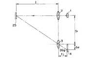
図4は本実施例の測距装置の要部を示す斜視図である。図中の座標軸はカメラ24の縦横を基準にして設定した座標軸であり、つまり、X方向はカメラ24の横方向、Y方向はカメラ24の縦方向、Z方向はカメラ24の厚さ方向にそれぞれ対応している。
【0048】
IRED1で発光した光は、上述のように、投光レンズ2を介して射出され、受光レンズ3を介して受光素子4上に受光像26を結ぶ。
【0049】
このとき、上記投光レンズ2の主点2gと受光レンズ3の主点3gとを結んでできる基線長はS1となっていて、受光レンズ3の主点3gから投光レンズ2の主点2gを見上げたときの水平方向に対する仰角はθである。そして、上記投光レンズ2の主点2gと受光レンズ3の主点3gのX方向寸法は基線長S3、Y方向寸法は基線長S2となっている。
【0050】
また、受光素子4のX方向,Y方向の寸法はそれぞれtx,tyとなっていて、該受光素子4上の受光像26の重心は26gである。
【0051】
この受光像26の重心26gは、受光レンズ3の光軸と受光素子4が交わる交点からの基線長S1方向の距離はΔuとなっていて、同交点からのX方向位置はΔx、Y方向位置はΔyである。
【0052】
上記反射光の受光像26の重心26gは、スポット欠けが発生することなく測距が行われた場合には、受光素子4上の1ライン上、すなわち投光レンズ2の主点2gと受光レンズ3の主点3gを結んだ基線長S1の方向と平行で受光レンズ3の光軸を通る受光素子4上のラインである基準ライン32上を通るようになっている。
【0053】
従って、上記ステップS4で出力した入射位置信号がこの基準ライン32上にあるかどうかで、スポット欠けが発生しているか否かの判定が可能であり、基準ライン32上でなければスポット欠けが発生しているし、基準ライン32上であればスポット欠けは発生していないと判定することができる。以上のようにして、スポット欠けが発生しているか否かの判定を行う。
【0054】
次に、被写体距離の算出は、受光素子4が出力する光電変換信号である電流Ia,Ib,Ic,Idから、受光素子4上の受光像26の重心26gの位置Δx,Δy,Δuを求めて、これらに基づいて三角測距の原理により被写体までの距離を演算すれば良い。
【0055】
これらΔx,Δyと電流Ia,Ib,Ic,Idの間には、以下のような関係がある。
【0056】
Δx=tx・Id/(Ic+Id) ……(1)
Δy=ty・Ib/(Ia+Ib) ……(2)
こうして、電流Ia,Ibから重心26gのY方向位置が、電流Ic,Idから重心26gのX方向位置が求められる。
【0057】
さらに、Δuは、図4から明らかなように、三平方の定理により、
Δu=sqar(Δx×Δx+Δy×Δy) ……(3)
と表すことができる。
【0058】
また、三角測距の原理から被写体距離を考えると、
被写体距離=受光レンズ焦点距離×基線長/受光像重心位置 …(4)
と表すことができる。
【0059】
図5は基線長をS1としたときの被写体25までの被写体距離lと受光像重心位置26gの関係を示す図である。ここにfjは、受光レンズ3の焦点距離である。この図5から明らかなように、基線長をS1としたときの被写体距離lの算出式は、上記(4)式から、
l=fj・S1/Δu ……(5)
と表すことができる。
【0060】
また、基線長をS2あるいはS3としたときの被写体距離lの算出式は、基線長S1のときと同様にして、
l=fj・S2/Δy ……(6)
l=fj・S3/Δx ……(7)
と表すことができる。
【0061】
このように、基線長S1,S2,S3のいずれに基づいても、被写体距離lを算出することができるが、どの基線長に基づいて算出した被写体距離lを用いるかの使い分けは、以下のように行う。
【0062】
スポット欠けが発生していない場合には、基線長をS1と考えて被写体距離を算出する。また、スポット欠けが発生した場合には、カメラが横位置であれば基線長をS2として被写体距離を算出し、カメラが縦位置であれば基線長をS3として被写体距離を算出する。
【0063】
このようにスポット欠けの発生の有無およびカメラの姿勢によって、基線長を適切に選択して被写体距離を算出するのは、次に説明する理由による。
【0064】
アクティブ式測距装置の場合には、上述したように、基線長方向にスポット欠けが発生すると誤測距してしまうことがあるが、基線長と直交する方向のスポット欠けではこの誤測距が発生することはない。よって、基線長方向とスポット欠けの方向が互いに直交する方向にあれば良いことになる。
【0065】
ここでスポット欠けの発生し易い方向について考えると、例えば被写体が人間であれば、鉛直方向は一般に身長方向となり、一方、水平方向は人の幅方向であることから、人の身長と幅の比を考えれば、スポット欠けは鉛直方向よりも水平方向に起こり易いことが容易に推測できる。
【0066】
こうして、基線長方向を鉛直方向にとった方がスポット欠けによる誤測距は起こりにくいと考えられるので、スポット欠けが発生した場合には、カメラが横位置であれば基線長をS2として被写体距離を算出し、カメラが縦位置であれば基線長をS3として被写体距離を算出する。
【0067】
また、スポット欠けが発生していない場合に基線長をS1として被写体距離を算出するのは、図2を見ても明らかなように、基線長S2,S3に比べて基線長S1が一番長いために、測距精度を高めることができるからである。
【0068】
以上説明したように、このような第1実施例によれば、スポット欠けの有無およびカメラの姿勢によって適切な基線長と受光位置信号を用いて被写体距離を算出するので、鉛直方向に比べてスポット欠けの発生し易い水平方向のスポット欠けが起きても誤測距することなく測距することができると共に、スポット欠けが発生していない場合は、基線長を長くとって被写体距離を演算することで測距精度を高めることができる。
【0069】
図6から図13は本発明の第2実施例を示したものである。この第2実施例において、上述の第1実施例と同様である部分については説明を省略し、主として異なる点についてのみ説明する。
【0070】
この第2実施例のカメラの測距装置には、図6に示すように、被写体に対して光束(測距用光)を投射するための光源としてキセノン管(以下、Xe管と略記する。)10が用いられていて、発光回路11により発光駆動されるようになっている。
【0071】
このXe管10の周りには、円筒形状のロールマスク12が回動自在に取り付けられていて、このロールマスク12には、該Xe管10の長手方向に直線をなす走査手段たるスリット状の開口部12a(図7(B)参照)が設けられている。
【0072】
そして、上記ロールマスク12の周りには、やはり円筒形状をなすロールマスク13が回動自在に取り付けられていて、このロールマスク13には、円周方向に真っ直ぐなスリット状の走査手段たる開口部13a(図7(A)参照)と、螺旋をなすスリット状の走査手段たる開口部13b(図7(A)参照)とが設けられている。
【0073】
これにより、上記ロールマスク12,13がそれぞれ有する開口部12aと開口部13a,13bとが重なった部分から、上記Xe管10の光の一部が射出されるようになっている。この射出された光は、投光レンズ2により集光され、被写体に向けて測距用光として投射される。
【0074】
なお、上述のXe管10とロールマスク12,13と投光レンズ2により、投光手段21が構成されている。
【0075】
上記ロールマスク12,13の端部には伝達部たるギヤー部12g,13gがそれぞれ一体的に設けられており、これらのギヤー部12g,13gはやはり伝達部をなすギヤー列14,15にそれぞれ噛合している。
【0076】
このギヤー列14,15の他端側は、走査方向切換手段たる遊星クラッチ18を介して駆動部たるモータ17に噛合していて、この遊星クラッチ18を操作することで、モータ17の駆動力をロールマスク12側とロールマスク13側とに切り替えて、それぞれを回転させるようになっている。
【0077】
上記モータ17は、モータドライバ16を介してCPU6により駆動制御されるものであり、その駆動状態は、円筒マスク位置検出手段35に入力されるようになっている。
【0078】
この円筒マスク位置検出手段35は、モータ17から入力した信号により、上記円筒マスク12,13の位置を検出して、その位置から上記投光手段21により投射される測距用光の投射方向を判別するものである。つまり、この第2実施例では、該円筒マスク位置検出手段35が投射方向検出手段に相当している。
【0079】
この円筒マスク位置検出手段35の検出結果は、CPU6と後述する補正手段36に出力されるようになっている。
【0080】
上記投光手段21から投射された測距用光は、被写体で反射した後、受光レンズ3を介して受光素子4上に結像するようになっている。なお、これら受光レンズ3および受光素子4により、受光手段22が構成されている。
【0081】
上記投光手段21と受光手段22とは、上述の第1実施例と同様に、基線長S1だけ離れて設置されており、この基線長方向S1は、カメラ24の横方向に対してθ傾いている。
【0082】
上記受光素子4は、上記測距用光が被写体で反射した光の入射位置を2次元で検知するための光電変換素子であり、上述の第1実施例と同様に、2次元位置検出用の半導体光位置検出素子からなっている。そして、該受光素子4は、カメラ24の横方向(X方向)と縦方向(Y方向)の入射位置を検知できるように設置されており、受光位置に応じて光電変換信号を出力するものである。
【0083】
この受光素子4の出力はオートフォーカス集積回路(AFIC)5に入力されるようになっていて、このAFIC5は、該受光素子4の出力に基づいて上記反射光のカメラの横方向(X方向)と縦方向(Y方向)との2方向の入射位置を算出して、上記補正手段36に出力するものである。
【0084】
この補正手段36は、上記AFIC5で算出した反射光の入射位置を上記円筒マスク位置検出手段35の出力に基づいて補正し、CPU6に出力するようになっている。
【0085】
また、このカメラの測距装置には、カメラ24の姿勢を検出する姿勢検出手段7が設けられていて、その検出結果をCPU6に出力するようになっている。
【0086】
上記CPU6は、カメラ全体のシーケンスを司るワンチップマイコン等からなる演算制御回路であり、上記円筒マスク位置検出手段35の出力に基づいてモータドライバ16に制御信号を送ってモータ17の駆動を制御するとともに、発光回路11に発光信号を送出して、Xe管10の発光タイミングを制御するものである。
【0087】
さらに、CPU6は、上記姿勢検出手段7の出力に基づいて測距用光の走査方向を決定して、上記モータ17の制御を行うようになっているとともに、上記補正手段36が出力した入射位置信号と上記姿勢検出手段7の出力とに基づいて上記被写体までの距離を算出して、その算出結果に基づいて撮影レンズ8の焦点調節を行うものである。
【0088】
なお、カメラ24の撮影画面は、上述の第1実施例と同様に、横方向であるX方向が長辺方向であり、縦方向であるY方向が短辺方向となっている。
【0089】
次に、モータ17を正転あるいは逆転することにより、被写体に投射する測距用光の走査方向が切り替わる機構について説明する。
【0090】
まず、遊星クラッチ18の動きを図9,図10を参照して説明する。図9は遊星クラッチ18の構成を示す斜視図である。
【0091】
図9に示すように、モータ17の出力軸には遊星クラッチ18の太陽ギヤーたるピニオンギヤー18aが回動一体に取り付けられていて、このピニオンギヤー18aは遊星ギヤー18bに噛合している。
【0092】
この遊星ギヤー18bは、上記ピニオンギヤー18aに回動自在に取り付けられた連接棒18cの一端部に、図示しないフリクション機構を介して取り付けられていて、この連設棒18cの他端部がストッパ18d,18eに当接することにより、その公転運動が規制されるようになっている。
【0093】
このように構成された遊星クラッチ18の作用を、図10(A),(B),(C)の遊星クラッチ18を示す側面図を参照して説明する。
図10(A)は、中立の状態を示しており、遊星ギヤー18bはギヤー列14,15のいずれとも噛合しておらず、この状態では走査は行わない。
【0094】
この状態からモータ17を図10(A)の矢印aの方向へ回転(正回転)させると、連接棒18cは、遊星ギヤー18bとの間の図示しないフリクション機構により、ピニオンギヤー18aの回転に従ってストッパ18dに当接するまで回転する。このときには、ピニオンギヤー18aの回転は連接棒18cが回転するために用いられて、遊星ギヤー18bは自転しない。
【0095】
連接棒18cがストッパ18dに当接すると、図10(B)に示すような状態になり、遊星ギヤー18bはギヤー列15と噛合して、モータ17の駆動力によりロールマスク13が回転する。
【0096】
この図10(B)に示す状態が、撮影画面の長辺方向に測距用光を走査するときの状態である。
【0097】
また、モータ17を図10(A)の矢印bの方向に回転(逆回転)させると、モータ17を正回転させたときと同様に、連接棒18cはピニオンギヤー18aの回転に従ってストッパ18eに当接するまで回転し、図10(C)に示すような状態になる。
【0098】
そして、遊星ギヤー18bはギヤー列14と噛合して、モータ17の駆動力によりロールマスク12が回転する。
【0099】
この図10(C)に示す状態が、撮影画面の短辺方向に測距用光を走査するときの状態である。
【0100】
続いて、ロールマスク12,13の回転により、測距用光の走査方向がどのように変化するかを説明する。
【0101】
図11(A)から図11(F)は、右側の図がロールマスク12とロールマスク13の位置関係を示すカメラ24の正面から見た図、左側の図がそのときのカメラ24側から見た撮影範囲34と投光像33との関係を示す図である。
【0102】
また、図中の座標軸は、カメラ24の正面から見た座標軸であり、X方向はカメラ24の横方向、Y方向はカメラ24の縦方向である。
【0103】
図11(A)は初期状態を、図11(B),図11(C)はロールマスク12を回転させたときの状態を、図11(D)から図11(F)はロールマスク13を回転させたときの状態を、それぞれ示している。
【0104】
モータ17を逆回転させてロールマスク12を回転させると、ロールマスク12は図11(A)中矢印b方向に回転する。
【0105】
すると、ロールマスク12の開口部12aとロールマスク13の開口部13aとが重なった部分は、ロールマスク12が回転することにより図11(A)に示す状態から図11(B)に示す状態へと変化し、さらに、図の裏側に開口部12aが一旦隠れた後、図11(C)へと順次変化して投光方向も変化する。
【0106】
つまり2つの開口部12a,13aが重なった部分が図中上下方向に移動し、投光レンズ2の主点とのなす角がカメラのY方向に変化することになり、カメラのY方向(撮影画面の短辺方向)に走査しながら投光することができる。
【0107】
つまり、図11(B),図11(C)に示したように、ロールマスク12を回転させたときは、撮影画面の短辺方向に走査して測距することになる。
【0108】
また、Xe管10の発光タイミングは、円筒マスク位置検出手段35の出力を参照して、CPU6が制御する。
【0109】
次に、上記図11(A)に示す状態において、モータ17を正回転させてロールマスク13を回転させると、ロールマスク13は同図11(A)中矢印a方向に回転する。
【0110】
すると、該図11(A)では裏側にあったロールマスク13の開口部13bが表側に現れて、開口部13bとロールマスク12に設けられた開口部12aとが重なった部分から測距用光が投射されることになる。
【0111】
さらにロールマスク13が回転することにより、開口部13bと開口部12aの重なった部分は、図11(A)に示す状態から、図11(D),図11(E),図11(F)に示す状態へと順次変化して、投光方向も変化する。
【0112】
つまり、開口部13bと開口部12aの重なった部分がXe管10の長手方向に移動して、投光レンズ2の主点とのなす角がカメラのX方向に変化することになり、すなわち、撮影画面の長辺方向であるカメラのX方向に走査しながら投光することができる。
【0113】
こうして、図11(D)から図11(F)に示したように、ロールマスク13を回転させたときは、撮影画面の長辺方向に走査して測距することになる。
【0114】
このときのXe管10の発光タイミングも、上記円筒マスク位置検出手段35の出力に基づいてCPU6により制御され、本実施例では、図11(A)の状態から図11(D)の状態になるまでの間は発光を行わず、図11(D)の状態になってから図11(F)の状態に至る間で、Xe管10の発光を行って測距を行う。
【0115】
なお、図11(A)の状態から図11(D)の状態に至る間も、Xe管10を発光して中央部のみ測距を繰り返して行い、その結果を平均化して中央部の測距データとすることで、中央部の測距データの精度を高めるようにしても良い。
【0116】
また、ロールマスク12,13の駆動方法については、本実施例に示す手段に限定されるものではなく、例えばディファレンシャルギヤー等を用いてモータ17の駆動力を切り替えるようにしても良いし、もちろん、ロールマスク12,13をそれぞれ別々のアクチュエータで駆動することも可能である。
【0117】
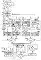
次に、図8に示すフローチャートを参照して、この第2実施例の作用を説明する。
カメラ24には、2段スイッチでなる図示しないレリーズ釦が設けられていて、このレリーズ釦の1段目の押し込み、つまり1stレリーズスイッチがオンになったことを検知すると(ステップS21)、測距回数を示す変数であるnを0にリセットし(ステップS22)、姿勢検出手段7の出力からカメラ24が水平方向に対し光軸を中心に何度傾いているかを検出して、どの方向に測距用光を走査するかをCPU6が決定する。
【0118】
このとき、この第2実施例では、カメラ24の傾きが水平方向に対して45°以上であるか否かを判断し(ステップS23)、カメラ24の傾きが水平方向に対して45°までであるときは、撮影画面の長辺方向に走査するものとし、カメラ24の傾きがそれより大きい場合には、撮影画面の短辺方向に走査するものとする。
【0119】
このステップS23において、撮影画面の長辺方向に走査すると決定した場合は、モータ17を正回転して遊星クラッチ18をギヤー列15に噛合させて、ロールマスク13を回転させる(ステップS24)。
【0120】
次に、nをインクリメントし(ステップS25)、発光回路11を駆動してXe管10を発光させ、測距用光として被写体に向けて投射する(ステップS26)。
【0121】
このステップS26で投射した測距用光の被写体での反射光を受光手段22が受光し(ステップS27)、受光素子4が光電変換信号を出力する。
【0122】
ステップS27で発光素子4が出力した光電変換信号からAFIC5がX方向とY方向の受光位置を算出し、補正手段36が円筒マスク位置検出手段35の出力に応じてX方向の受光位置に補正を掛ける(ステップS28)。
【0123】
ステップS28で算出したY方向の受光位置および補正されたX方向の受光位置から、スポット欠けが発生しているか否かをCPU6が判定する(ステップS29)。
【0124】
スポット欠けが発生していると判定された場合は、ステップS28で算出したY方向の受光位置から基線長をS2としてCPU6が被写体距離を算出し(ステップS30)、後述するステップS32へと進む。
【0125】
一方、上記ステップS29でスポット欠けが発生していないと判定された場合は、上記ステップS28で算出したY方向の受光位置および補正されたX方向の受光位置から、基線長をS1としてCPU6が被写体距離を算出する(ステップS31)。
【0126】
次に、上記測距回数を示す変数nがn=7であるか否かを判定し(ステップS32)、n=7になっていなければ上記ステップS25へと戻って、n=7になるまで上述のステップS25からステップS32を繰り返す。
【0127】
一方、上記ステップS23において撮影画面の長辺方向に走査しないと判定した場合には、モータ17を逆回転させる(ステップS33)。
【0128】
そして、nをインクリメントし(ステップS34)、発光回路11を駆動してXe管10を発光させ、測距用光として被写体に向けて投射する(ステップS35)。
【0129】
このステップS35で投射した測距用光の被写体での反射光を受光手段22が受光し(ステップS36)、受光素子4が光電変換信号を出力する。
【0130】
ステップS36で発光素子4が出力した光電変換信号からAFIC5がX方向とY方向との受光位置を算出し、補正手段36が円筒マスク位置検出手段35の出力に応じてY方向の受光位置に補正を掛ける(ステップS37)。
【0131】
ステップS37で算出したX方向の受光位置および補正されたY方向の受光位置から、スポット欠けが発生しているか否かをCPU6が判定する(ステップS38)。
【0132】
スポット欠けが発生していると判定された場合は、ステップS37で算出したX方向の受光位置から基線長をS3として、CPU6が被写体距離を算出して(ステップS39)、後述するステップS41へと進む。
【0133】
一方、上記ステップS38でスポット欠けが発生していないと判定された場合は、上記ステップS37で算出したX方向の受光位置とステップS37で算出し補正したY方向受光位置から、基線長をS1としてCPU6が被写体距離を算出する(ステップS40)。
【0134】
次に、測距回数を示す変数であるnがn=7になったか否かを判定し(ステップS41)、n=7になっていなければ上記ステップS34へと戻って、n=7になるまで上述のステップS34からステップS41を繰り返す。
【0135】
上記ステップS32またはステップS41においてn=7になったと判定された場合は、CPU6は、上記ステップS25からステップS32までか、あるいは上記ステップS34からステップS41までの繰り返しによって得られた7個の測距データのうち、最も近い測距データを選択する(ステップS42)。
【0136】
そして、図示しない測光手段が被写体輝度を測定してCPU6に出力し、CPU6がその被写体輝度に適合した撮影レンズ8の図示しないシャッタ機構の開口時間と絞り値を決定する(ステップS43)。
【0137】
その後、上記レリーズ釦の2段目の押し込みがされたか否かを判定し(ステップS44)、レリーズ釦の2段目の押し込みがなされてないときは、レリーズ釦の1段目の押し込みがされたか否かを判定し(ステップS47)、レリーズ釦の1段目の押し込みが検知されれば上記ステップS44へと戻り、レリーズ釦の1段目の押し込みが検知できなければ上記ステップS21へと戻る。
【0138】
また、上記ステップS44においてレリーズ釦の2段目の押し込みを検知すると、上記ステップS42で選択した測距データに基づいてCPU6が撮影レンズ8の焦点調節を行い、上記ステップS43で決定したシャッタ開口時間と絞り値に従って、CPU6が図示しないシャッタ機構の開閉を制御して撮影を行い(ステップS45)、撮影が終了した後は撮影レンズ8を初期位置に戻す。
【0139】
そして、例えばフォトリフレクタ等の図示しない位置検出手段の出力に基づいて、CPU6がモータ17を制御することにより、走査手段たる開口部12a,13a,13bを備えたロールマスク12,13を図11(A)に示す位置に初期化して(ステップS26)、本シーケンスを終了する。
【0140】
ここで測距用光の投射方向によって受光位置信号を補正して被写体距離を演算する理由について説明する。
【0141】
図12は本実施例のカメラの測距装置における測距用光の投射方向と反射光の入射位置の関係を示す斜視図である。図中の座標軸はカメラ24の縦横を基準にして設定した座標軸であり、つまり、X,Y,Z方向はそれぞれカメラ24の横方向,縦方向,厚さ方向にそれぞれ対応している。
【0142】
Xe管10で発光してロールマスク12の開口部12aとロールマスク13の開口部13a,13bの重なった部分を通過した光は、投光レンズ2を介して射出され、被写体25で反射された後、受光レンズ3を介して受光素子4上に受光像26を結ぶ。
【0143】
このとき、上記投光レンズ2の主点2gと受光レンズ3の主点3gとを結んでできる基線長はS1となっていて、受光レンズ3の主点3gから投光レンズ2の主点2gを見上げたときの水平方向に対する仰角はθである。そして、上記投光レンズ2の主点2gと受光レンズ3の主点3gのX方向寸法は基線長S3、Y方向寸法は基線長S2となっている。
【0144】
また、受光素子4のX方向,Y方向の寸法はそれぞれtx,tyとなっていて、該受光素子4上の受光像26の重心は26gである。
【0145】
この受光像26の重心26gは、受光レンズ3の光軸と受光素子4が交わる交点からの重心26gの基線長S1方向の距離はΔuとなっていて、同交点からのX方向位置はΔx、Y方向位置はΔyである。
【0146】
一方、上記投光レンズ2の光軸に対してX−Z平面上で角度ζをなす測距用光を投射したときには、その受光素子4上の受光像26の重心は26gζとなっていて、このときのX方向位置はΔxζ、Y方向位置はΔyζである。
【0147】
測距用光を投光レンズ2の光軸方向に投射したときと、この光軸に対してX−Z平面上で角度ζをなすように投射したときとでは、図から明らかなように、受光素子4上の反射光の入射位置は、Y方向には変化しないが、X方向にはズレを生じる。
【0148】
よって、光軸方向に測距用光を投射したときと同じように演算処理すると誤測距してしまうために、演算する際に投射方向による補正を掛ける必要がある。
【0149】
この補正方法について、図12を参照して引き続いて説明する。
基線長をS3としてX方向の受光位置から被写体距離を算出すると、投光レンズ2の光軸に沿って測距用光を投射した場合(走査角0°)は、
l=fj・S3/Δx ……(8)
と表すことができる。ここにfjは、受光レンズ3の焦点距離である。
【0150】
一方、投光レンズ2の光軸に対してX−Z平面上で角度ζをなす方向に測距用光を投射した(走査角ζ)場合は、走査角0°で測距用光を投射したときに比べてX方向に受光位置が変化するので、
l:fj=(S3+l・tanζ):Δxζ ……(9)
となり、
l=fj・S3/(Δxζ−fj・tanζ) ……(10)
と表すことができる。
【0151】
よって(8)式および(10)式から、ΔxとΔxζの関係式は、
Δx=Δxζ−fj・tanζ ……(11)
と表すことができる。
【0152】
こうして、X方向の受光位置は測距用光の投射方向(走査角ζ)に応じて、(11)式に示すような補正を掛ければ良いことになる。
【0153】
また、Y方向の受光位置は、走査角0°で測距用光を投射したときと走査角ζで投射したときでは変化しないために、ΔyとΔyζの関係は、
Δy=Δyζ ……(12)
と表すことができて、Y方向の受光位置にはなんら補正を掛ける必要がないことが分かる。
【0154】
よって、測距用光の走査方向に平行な方向の受光位置は走査角により変化して、このときには補正式は(11)式のように表すことができ、一方、走査方向と直交する方向の受光位置は走査角によって変化しないために、なんら補正を掛ける必要はない。
【0155】
さらに、スポット欠けが発生しているか否かの判定は、走査角に応じて補正を掛けた受光位置が、上述の第1実施例と同様にして、基準ライン32上にあるかどうかで行うことができる。つまり、基準ライン32上にあればスポット欠けは発生していないと判定し、基準ライン32上になければスポット欠けが発生していると判定すれば良い。
【0156】
また、本実施例では、撮影画面の長辺方向と短辺方向に走査して測距を行ったが、ロールマスク12,13に設けられた開口部の形状や、駆動パターンを変えれば多種多様な走査方向を得ることができる。
【0157】
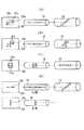
図13は、ロールマスク12,13の開口部の形状と、走査方向の一例を示す図である。
【0158】
図中矢印12sは、ロールマスク13が図の状態にあるときにロールマスク12を回転させたときの走査方向であり、矢印13sは、ロールマスク12が図の状態にあるときにロールマスク13を回転させたときの走査方向を示す。
【0159】
図13(A)に示すように、ロールマスク12には長手方向に伸びたスリット形状の開口部が設けられ、ロールマスク13には螺旋状に伸びたスリット形状の開口部が設けられている。この図13(A)に示す場合には、ロールマスク12とロールマスク13のいずれかを回転させることにより、撮影画面に対して長辺方向と斜め方向に走査することができる。
【0160】
図13(B)に示すように、ロールマスク12には長手方向に伸びたスリット形状の開口部が設けられ、ロールマスク13には螺旋状に伸びたスリット形状の開口部と円周方向に伸びたスリット形状の開口部とが組み合わせて設けられている。この図13(B)に示す場合には、画面の長辺方向と短辺方向および斜め方向に走査することができるとともに、ロールマスク13のみを回転させたときは、上述の画面長辺方向に走査しつつ、画面の中央部1点に連続的に測距用光を投射することができる。
【0161】
図13(C)に示すように、ロールマスク12には円形孔と、この円形孔を中心として対向する2つの円弧状スリットをなす開口部が設けられていて、ロールマスク13には長手方向に伸びたスリット形状の開口部が設けられている。この図13(C)に示す場合には、画面の中央部1点と画面の長辺方向および画面の中央を中心とした円弧状に走査することができる。
【0162】
図13(D)に示すように、ロールマスク12には、表側に長手方向に伸びたスリット形状の開口部が、裏側に円周方向に伸びたスリット形状の開口部が設けられ、ロールマスク13には螺旋状に伸びたスリット形状の開口部が設けられている。この図13(D)に示す場合には、ロールマスク12の表側と裏側に異なった形状の開口部を設けたことにより、ロールマスク12の表側と裏側を切り替えて使えば、ロールマスク13の回転だけで画面の長辺方向と短辺方向の両方向に走査することができる。
【0163】
また、上述では、ロールマスク12,13の一方を動かすときは、他方を固定していたが、例えば図13(A)の場合では、ロールマスク12をステップ駆動しながら、ロールマスク13を回転させることにより、破線部12hの範囲内を全て走査することができて、つまり2次元的な測距範囲を得ることができる。このように2つのロールマスク12,13を独立に回転させることで、2次元的な測距範囲を得ることが可能である。
【0164】
また、本実施例では、スリット状の開口部を有する2つのロールマスクを回転させて測距用光を走査していたが、2枚の平板にスリット状の開口部を設けて、これらを相対的に動かしても測距用光を走査することができることはいうまでもない。
【0165】
さらに、本実施例では、ロールマスクに細長いスリット状の開口部を設けているが、ロールマスクに小孔を複数個穿設して開口部としてももちろん良い。
【0166】
加えて、ここまでは走査方向を切り替える方法例について述べてきたが、本実施例のようなロールマスクによる走査手段であれば、測距用光の結像距離を変化させることもできる。
【0167】
つまり、外側のロールマスクの回転軸に垂直な断面の形状を、例えば楕円や、これに準じた回転軸からの距離が回転角により異なる断面形状のものにするか、あるいは、ロールマスクの回転軸をロールマスクの中心軸に対して偏心させて、外側のロールマスクを回転させれば、Xe管10から光線を取り出す開口部と投光レンズ2の主点との距離が変化して、上記測距用光の結像距離を変化させることができる。
【0168】
よって、測距用光の結像距離を測距装置の測距範囲内の距離で変化させれば、被写体距離がどこであっても測距用光が良好なピントで被写体上に結像するので、そのときの距離情報を用いて測距精度を高めることも可能である。
【0169】
なお、被写体に測距用光が良好なピントで結像したかどうかの判定法は、受光素子の受光光量を検出して、受光光量が最も大きいときが良好なピントで結像したと判定しても良いし、投光レンズ2の焦点距離は既知であるので、そのときの投光レンズ2の主点2gからロールマスクの開口部までの距離と、被写体距離情報とから判断しても良い。
【0170】
例えば、図13(B)に示したロールマスクの組合せの場合には、ロールマスク13をロールマスク12の外側に設置し、ロールマスク13の中心軸に対して偏心させてロールマスク13を回転させれば、撮影画面の中央1点については、測距装置における最至近測距距離から最遠測距距離まで変化させることも可能である。
【0171】
このとき、受光素子4も測距用光の結像距離にある投光像が該受光素子4上に結像するように受光レンズ3の光軸方向に動かせば、より測距精度を高めることができる。さらにこのとき、外側のロールマスクの開口部のエッジ部分が、投受光の基線長方向である方が望ましい。
【0172】
また本実施例では、複数ケ所の測距情報のうち最至近のものを無条件で選択しているが、スポット欠けの発生している箇所の距離情報はキャンセルして、スポット欠けのない距離情報のみを使用して測距精度を高めるようにしても良い。
【0173】
さらに本実施例では、測距用光の投射方向を検出して受光位置に補正を掛けて被写体距離を演算しているが、上述したように、走査方向と直交する方向の受光位置は走査の影響を受けないので、スポット欠けによる影響を考慮しなくとも良ければ、本実施例のように投射方向検出手段と補正手段を設けなくとも、走査方向に直交する方向の受光位置のみにより、被写体距離を演算することも可能である。
【0174】
またこのときは、走査方向と平行な方向の受光位置から投射方向を算出して、投射方向検出手段として利用することも可能である。この場合、投受光の配置は画面の斜め方向には限定されず、走査方向と同方向でなければ良い。なぜならば、走査方向と基線長方向が同方向であると、その直交方向において基線長が0となり、被写体距離を演算することができないからである。
【0175】
さらに本実施例では、被写体で反射した測距用光の受光位置を、走査角に応じて補正して被写体距離を演算しているが、各走査角に応じた調整値を予め記憶手段等に記憶させておいても良い。
【0176】
また本実施例において、カメラが横位置のときにカメラのX方向に走査し、カメラが縦位置のときにカメラのY方向に走査するのは、走査方向を常に水平方向とすることで、人物が2人並んで撮影するとき等に起こりがちな、いわゆる中抜けを防止するためである。
【0177】
以上説明したようにこの第2実施例によれば、簡単な構成で撮影においてカメラを縦に構えても横に構えても常に適切な範囲を測距できるように走査方向を切り替えることができて、中抜けを効果的に防止することができるとともに、スポット欠けの発生の有無とカメラの姿勢によって適切な基線長方向を選択して被写体距離を算出しているので、誤測距することなく高精度な測距を行うことができる。
【0178】
さらに本実施例を応用すれば、上述したように、測距用光の投射方向を検出することなく正確な測距を行うことも可能である。
【0179】
図14から図16は本発明の第3実施例を示したものであり、図14はカメラの測距装置を示すブロック図である。この第3実施例において、上述の第1,第2実施例と同様である部分については説明を省略し、主として異なる点についてのみ説明する。
【0180】
図示のように、このカメラの測距装置には、測距用の光束を被写体に投射するための光源である赤外発光ダイオード(IRED)1が設けられていて、このIRED1は、ドライバ9により発光制御されるようになっている。
【0181】
上記IRED1の発光部1aは細長い形状に形成されていて、このIRED1が発した光は、投光レンズ2により集光されて測距用光として被写体に向けて投射される。なお、上記IRED1,投光レンズ2およびドライバ9により、投光手段21が構成されている。
【0182】
上記IRED1は、IRED回転手段38により、上記投光レンズ2の光軸周りに回転駆動されるように構成されていて、これにより、撮影画面の長辺方向(X方向)に細長い投光像と、撮影画面の短辺方向(Y方向)に細長い投光像とを、上記被写体に向けて投射することが可能となっている。
【0183】
上記測距用光を受けた被写体からの反射光は、受光レンズ3を介して受光素子4上に結像するようになっていて、これら受光レンズ3および受光素子4により受光手段22が構成されている。
【0184】
上記投光手段21と受光手段22は、上述の第1,第2実施例と同様に、撮影画面の縦横に対して斜め方向に基線長S1だけ離れて設置されている。
【0185】
上記受光素子4は、上記測距用光の反射光の入射位置を2次元で検知するための光電変換素子であり、例えば2次元位置検出用の半導体光位置検出素子からなり、カメラ24の横方向(X方向)と縦方向(Y方向)の入射位置を検知できるように設置され、受光位置に応じて光電変換信号を出力するものである。
【0186】
オートフォーカス集積回路(AFIC)5は、上記受光素子4の出力に基づいて上記反射光のカメラの横方向(X方向)と縦方向(Y方向)の2方向の入射位置を算出するものである。このAFIC5の入射位置信号は、判定手段37に入力されるようになっている。
【0187】
この判定手段37は、AFIC5の出力信号からスポット欠けの影響がない受光位置信号を選択して、CPU6に出力するものである。
【0188】
上記CPU6は、カメラ全体のシーケンスを司るワンチップマイコン等からなる演算制御回路であり、上記判定手段37が選択した受光位置信号から上記被写体までの距離を算出し、その算出結果に基づいて撮影レンズ8の焦点調節を行うものである。
【0189】
なお、カメラ24の撮影画面は、横方向であるX方向が長辺方向であり、縦方向であるY方向が短辺方向となっている。
【0190】
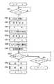
次に、図15を参照して第3実施例の作用を説明する。
カメラ24には、2段スイッチでなる図示しないレリーズ釦が設けられていて、このレリーズ釦の1段目の押し込み、つまり1stレリーズスイッチがオンになったことを検知すると(ステップS51)、IRED回転手段38によりIRED1の位置を初期化して横長位置にし(ステップS52)、この横長の初期位置においてドライバ9を駆動してIRED1を発光し、測距用光として被写体に向けて投射する(ステップS53)。
【0191】
上記IRED1の初期位置は、発光部1aの長手方向がカメラのX方向になっている位置であるために、上記ステップS53で投射された測距用光の被写体上での投光像は、X方向に細長い投光像(横長投光)となる。
【0192】
次に、上記ステップS53で投射した測距用光の被写体での反射光を、受光素子4が受光する(ステップS54)。
【0193】
AFIC5が、上記反射光の受光位置をカメラの横方向(X方向)と縦方向(Y方向)の受光位置信号として算出して、上記判定手段37へ出力する(ステップS55)。
【0194】
次に、IRED回転手段38によりIRED1を回転駆動して、上記IRED1の発光部1aの長手方向をカメラの縦方向であるY方向にした後、ドライバ9によりIRED1を発光させて、測距用光として被写体に向けて投射する(ステップS56)。
【0195】
つまり、このステップS56で投射される測距用光の被写体上での投光像は、Y方向に細長い投光像(縦長投光)となる。
【0196】
次に、上記ステップS56で投射した測距用光の被写体での反射光を、受光素子4が受光する(ステップS57)。
【0197】
このステップS57で受光した上記反射光の受光位置を、AFIC5がX方向とY方向の受光位置信号として算出し、判定手段37へと出力する(ステップS58)。
【0198】
そして、上記ステップS55とステップS58とでAFIC5が出力した受光位置信号のうち、スポット欠けの影響のない受光位置信号を判定手段37が選択してCPU6に出力し、CPU6が、この受光位置信号から上記被写体までの距離を算出する(ステップS59)。
【0199】
上記レリーズ釦の2段目の押し込みがなされたか否かを判定し(ステップS60)、レリーズ釦の2段目の押し込みが検知されない場合には、レリーズ釦の1段目の押し込みがなされているかを再確認し(ステップS61)、1段目の押し込みがなされていれば上記ステップS60へと戻り、1段目の押し込みがなされていなければ上記ステップS51へと戻る。
【0200】
一方、上記ステップS60において、レリーズ釦の2段目の押し込みが検知さた場合には、図示しない測光手段により上記被写体の輝度を測定し、CPU6が撮影レンズ8の図示しないシャッタ機構の開口時間と絞り値とを決定する(ステップS62)。
【0201】
そして、上記ステップS59で算出した被写体距離に従って撮影レンズ8の焦点調節をCPU6が行い、ステップS62で決定したシャッタ機構の開口時間と絞り値に基づいて、CPU6が、上記シャッタ機構の開口を制御して撮影を行い(ステップS63)、撮影が終了したら、撮影レンズ8の焦点位置を初期化してから本シーケンスを終了する。
【0202】
ここで、横長投光と縦長投光を行って、スポット欠けの影響のない上記反射光の受光位置を判定手段37が選択する選択方法について、図16を参照して説明する。
【0203】
この図16(A)から図16(D)において、左側の図はカメラ24側から見た被写体25上における横長の投光像33aおよび縦長の投光像33bの位置を示す図、右側の図はカメラ24の正面側から見た上記投光像33a,33bに係る受光素子4上の各受光像の受光像重心26ga,26gbを示す図である。また、図中の座標軸は、カメラ24を正面から見たときのカメラ24の座標軸であり、X方向はカメラ24の横方向、Y方向はカメラ24の縦方向にそれぞれ対応している。
【0204】
図16(A)は横長投光、縦長投光ともにスポット欠けが発生することなく被写体25に測距用光が投射されているときの図であり、この場合に比べて、図16(B),(C),(D)に示すように、スポット欠けが発生したときは、受光像の重心位置がずれることが分かる。
【0205】
このときに、細長い投光像であればスポット欠けは投光像の長辺方向に発生し易いことは明らかであるから、スポット欠けが発生した場合には、そのときの投光像の短辺方向の受光像重心位置は変化しないと考えられる。
【0206】
よって図16(B)に示すように、横長投光の受光像のみにスポット欠けが発生した場合は、縦長投光時の受光像重心26gbはスポット欠けが発生していないので、この受光像重心26gbについてはX方向,Y方向ともにスポット欠けの影響を受けていないし、また、受光像重心26gaについてもY方向はスポット欠けしていないときと同じ値である。
【0207】
図16(C)は横長投光と縦長投光の両方ともにスポット欠けが発生しているときの図であり、同図16(C)の符号33a,33bに示すように投光像が投射されてどちらも基準ライン32上にない場合には、受光像重心26gaのY方向の位置と、受光像重心26gbのX方向の位置は変化していないと考えられる。
【0208】
また、図16(D)は、縦長投光時に全く測距用光が被写体に投射されていないときの図であり、同図16(D)に示したようなスポット欠けが発生しているときは、縦長投光時は被写体に測距用光が投射されていないので受光出力はないが、横長投光時のY方向の受光像重心位置をスポット欠けの影響のない受光位置信号として用いることができる。
【0209】
つまり、スポット欠けが発生した場合は、そのときの投光像の短辺方向の受光像重心位置を、スポット欠けの影響のない受光位置信号として用いれば良いことになる。
【0210】
また、そのときスポット欠けが発生しているか否かの判定については、上述の第1実施例で説明したように、基準ライン32上に上記受光像重心があるかどうかで判定すれば良い。
【0211】
以上のような理論に基づいて、スポット欠けが発生したときに、スポット欠けの影響のない受光位置信号を判定手段37が選択する。
【0212】
つまり、被写体距離の算出は、縦長投光と横長投光の両方ともにスポット欠けが発生していなければ、縦長投光もしくは横長投光で得られる2つの受光位置信号から基線長をS1として被写体距離を算出すれば良い。
【0213】
また、縦長投光と横長投光の内のどちらか1方のみにスポット欠けが発生している場合は、スポット欠けが発生していない方のX方向およびY方向の受光位置信号を用いて、基線長をS1として被写体距離を算出すれば良い。
【0214】
さらに、縦長投光と横長投光の両方ともにスポット欠けが発生している場合は、縦長投光時のX方向の受光位置信号と横長投光時のY方向の受光位置信号とから、基線長をS1として被写体距離を算出すれば良い。
【0215】
加えて、これら縦長投光と横長投光の内のどちらか1方が被写体に全く投射されなかった場合には、被写体に投射されている方の受光位置信号の内、短辺方向の受光位置信号を用いて被写体距離を算出する。
【0216】
すなわち、縦長投光のみ被写体に投射されている場合は、この縦長投光時のX方向の受光位置信号を用いて基線長はS3として被写体距離を算出し、横長投光時のみ被写体に投射されている場合は、横長投光時のY方向の受光位置信号を用いて基線長はS2として被写体距離を算出する。
【0217】
各基線長S1,S2,S3の定義は上述の第1,第2実施例と同様であり、被写体距離の演算方法も上述の第1実施例で説明した通りである。
【0218】
また、本実施例では、縦長投光と横長投光にともにスポット欠けが発生していないときに、縦長投光か横長投光のどちらかの受光位置信号を用いて被写体距離を算出しているが、縦長投光時と横長投光時の各々の受光位置信号を用いて被写体距離を算出して、2つの距離情報を平均化することにより、測距の信頼性を高めるようにしても良い。
【0219】
さらに、本実施例では、横長投光時にスポット欠けが発生していなくても縦長投光を行うが、横長投光時にスポット欠けが発生していないときは、縦長投光を行わずに横長投光の結果のみで被写体距離を算出して、測距の高速化を図ることも可能である。
【0220】
なお、本実施例では、横長投光と縦長投光を行う順番についてはなんら制限はないが、カメラの姿勢を検知する姿勢検出手段を別途設けて、カメラが横位置であると検出されたときには縦長投光を先に行い、カメラが縦位置であると検出されたときには横長投光を先に行うようにすれば、1回目の投光時においてスポット欠けが発生する可能性がより低くくなり、測距の高速化が可能となる。
【0221】
また、カメラが横位置のときに縦長投光を行い、縦位置のときに横長投光を行うとスポット欠けが起きづらくなるのは、本実施例で説明した投光像の形状によりスポット欠けの発生しづらい方向と、上述の第1実施例で説明したカメラの姿勢によってスポット欠けの発生し易い方向とを同方向としているためである。
【0222】
このような第3実施例によれば、同一の投光手段を用いて縦長投光と横長投光を行うことにより、複数の受光手段を設けることなく、スポット欠けが発生しても誤測距することがない、高精度の測距が可能なカメラの測距装置となる。
【0223】
[付記]
以上詳述したような本発明の上記実施態様によれば、以下のごとき構成を得ることができる。
【0224】
(1) カメラの測距装置において、
発光光束を被写体に向けて投射する投光手段と、
上記投光手段の光束の投射方向を変化させ被写体上を走査する走査手段と、
上記光束の投射方向を検出する投射方向検出手段と、
上記投光手段から、撮影画面の縦横に対して斜め方向に配置し、上記被写体からの反射光位置を2次元的に検出し、撮影画面の略縦方向と略横方向の入射位置情報を出力する受光手段と、
上記受光手段の入射位置情報出力を上記投射方向検出手段の出力に応じて補正する補正手段と、
上記受光手段からの出力に応じて上記被写体までの距離を算出する演算手段と、
カメラの姿勢を検出する姿勢検出手段と、
上記投光手段の投射光束が被写体に全て投射されているか否かを判定する判定手段と、
上記姿勢検出手段の出力に応じて上記走査手段の走査方向を選択し切り替える制御手段と、
を有し、上記演算手段は、上記判定手段が上記光束の一部しか被写体に投射されていないと判断した場合は、上記姿勢検出手段の出力に応じて上記受光手段が有する撮影画面の略縦方向と略横方向とのいずれか1方向の入射位置情報出力を用いて上記被写体距離を演算し、上記判定手段が上記光束の全て被写体に投射されていると判断した場合は、上記受光手段が有する撮影画面の略縦方向と略横方向との2方向の入射位置情報出力を用いて上記被写体距離を演算することを特徴とするカメラの測距装置。
【0225】
(2) カメラの測距装置において、
発光光束を被写体に向けて投射する投光手段と、
上記投光手段の光束の投射方向を変化させ被写体上を走査する走査手段と、
上記投射方向を検出する投射方向検出手段と、
上記投光手段から基線長だけ離れて配置され、上記被写体から投射された光束の被写体での反射光を受光し、その入射位置を検出する受光手段と、
上記受光手段の入射位置情報出力を上記投射方向検出手段の出力に応じて補正する補正手段と、
上記補正手段の出力に応じて上記被写体までの距離を算出する演算手段と、
カメラの姿勢を検出する姿勢検出手段と、
上記姿勢検出手段の出力に応じて上記走査手段の走査方向を選択し切り替える制御手段と、
を具備することを特徴とするカメラの測距装置。
【0226】
(3) 光源からの光束を被写体に向けて投射する投光手段と、上記投光手段の光束の投射方向を切り替える走査手段とを有するカメラの測距装置において、
上記走査手段は、開口部を有する第1の円筒マスクと、この第1の円筒マスクの内側もしくは外側に設置される開口部を有する第2の円筒マスクとからなり、上記2つの円筒マスクを相対的に動かすことにより投射方向を切り替えることを特徴とするカメラの測距装置。
【0227】
(4) 上記走査手段は、上記第1および第2の円筒マスクの駆動を切り替えることにより走査方向を切り替えることを特徴とする付記3に記載のカメラの測距装置。
【0228】
(5) 上記第1の円筒マスクは開口部を2つ以上有し、上記第2の円筒マスクは1つの開口部を有し、この第2の円筒マスクを回転することにより投射方向を変化させ、上記第1の円筒マスクを選択的に動かすことにより走査方向を切り替えることを特徴とする付記3に記載のカメラの測距装置。
【0229】
(6) カメラの測距装置において、
発光光束を被写体に向けて投射する投光手段と、
上記投光手段から、撮影画面の縦横に対して斜め方向に配置すると共に、上記被写体からの反射光位置を2次元的に検出し入射位置情報を出力する受光手段と、
上記受光手段からの出力に応じて上記被写体までの距離を算出する演算手段と、
上記受光手段に基づき、上記投光手段の投射光束が被写体に全て投射されているか否かを判定する判定手段と、
上記判定手段が上記光束の一部しか被写体に投射されていないと判断した場合は、撮影者に警告する警告手段と、
を具備することを特徴とするカメラの測距装置。
【0230】
(7) カメラの測距装置において、
発光光束を被写体に向けて投射する投光手段と、
上記投光手段から、撮影画面の縦横に対して斜め方向に配置すると共に、上記被写体からの反射光位置を2次元的に検出し入射位置情報を出力する受光手段と、
上記光束が、被写体に全て投射されているか否かを判定する判定手段と、
上記受光手段からの出力に応じて上記被写体までの距離を算出する演算手段と、
を有し、上記投光手段は1回の測距動作で被写体に向けて2種類の異なる形状の光束を投射し、上記演算手段は、上記判定手段の出力に応じて上記2種類の異なる形状の光束の上記反射光の入射位置情報出力から1つ以上を選択して、被写体距離を算出することを特徴とするカメラの測距装置。
【0231】
(8) 上記光束の形状が上記受光手段の入射位置検出方向と同方向に細長いことを特徴とする付記7に記載のカメラの測距装置。
【0232】
(9) 発光光束を被写体に向けて投射する投光手段と、この投光手段の光束の投射方向を切り替える走査手段と、を有するカメラの測距装置において、
上記走査手段は、開口部を有する第1の円筒マスクと、この第1の円筒マスクの外側に設置される開口部を有する第2の円筒マスクとからなり、この第2の円筒マスクの回動軸が上記第2の円筒マスクの中心軸に対し偏心して配設され、上記第2の円筒マスクを回動することにより上記光束の投射方向を切り替えることを特徴とするカメラの測距装置。
【0233】
(10) 発光光束を被写体に向けて投射する投光手段と、この投光手段の光束の投射方向を切り替える走査手段と、を有するカメラの測距装置において、
上記走査手段は、開口部を有する第1の円筒マスクと、この第1の円筒マスクの外側に設置されていて、開口部を有するとともに、円筒マスクの断面形状が楕円である第2の円筒マスクとからなり、この第2の円筒マスクを回動することにより上記光束の投射方向を切り替えることを特徴とするカメラの測距装置。
【0234】
(11) 上記円筒マスクの代わりに平板によってマスクを形成することを特徴とする付記3または付記4に記載のカメラの測距装置。
【0235】
(12) マスクに小孔を複数個設けていることを特徴とする付記3または付記4または付記10または付記11に記載のカメラの測距装置。
【0236】
(13) カメラの測距装置において、
発光光束を被写体に向けて投射する投光手段と、
上記投光手段の光束の投射方向を変化させ被写体上を走査する走査手段と、
上記投光手段から、撮影画面の縦横に対して斜め方向に配置すると共に、上記被写体からの反射光位置を2次元的に検出し入射位置情報を出力する受光手段と、
上記受光手段からの出力に応じて上記被写体までの距離を算出する演算手段と、
カメラの姿勢を検出する姿勢検出手段と、
上記走査手段の走査方向は撮影画面の短辺方向と長辺方向との2方向であり、上記姿勢検出手段の出力に応じて上記走査手段の2つの走査方向を選択し切り替える制御手段とを有し、横構図のときには長辺方向に走査し、縦構図のときには短辺方向に走査することを特徴とするカメラの測距装置。
【0237】
(14) カメラの測距装置において、
発光光束を被写体に向けて投射する投光手段と、
上記投光手段から、撮影画面の縦横に対して斜め方向に配置すると共に、上記被写体からの反射光位置を2次元的に検出し入射位置情報を出力する受光手段と、
上記受光手段からの出力に応じて上記被写体までの距離を算出する演算手段と、
カメラの姿勢を検出する姿勢検出手段と、
上記受光手段に基づき、上記投光手段の投射光束が被写体に全て投射されているか否かを判定する判定手段と、
を有し、上記演算手段は、上記判定手段が上記光束の一部しか被写体に投射されていないと判断した場合は、撮影レンズの絞りを絞り込んで撮影することを特徴とするカメラの測距装置。
【0238】
【発明の効果】
以上説明したように本発明のカメラの測距装置によれば、受光手段を増やすことなくスポット欠けによる誤測距を防止することができる。
【0239】
また、本発明のカメラの測距装置によれば、投光手段を増やすことなく中抜けを防止することができる。
【図面の簡単な説明】
【図1】本発明の第1実施例のカメラの測距装置の構成を示すブロック図。
【図2】上記第1実施例の測距装置の投光レンズと受光レンズの位置関係を示すカメラの正面図。
【図3】上記第1実施例のカメラの作用を示すフローチャート。
【図4】上記第1実施例のカメラの測距装置の要部を示す斜視図。
【図5】上記図4のカメラの測距装置の要部の側面図。
【図6】本発明の第2実施例のカメラの測距装置の構成を示すブロック図。
【図7】上記第2実施例のロールマスクの開口部を示す展開図。
【図8】上記第2実施例のカメラの作用を示すフローチャート。
【図9】上記第2実施例の遊星クラッチを示す斜視図。
【図10】上記第2実施例の遊星クラッチが、(A)中立状態,(B)外側のロールマスクに駆動力を伝達する状態,(C)内側のロールマスクに駆動力を伝達する状態をそれぞれ示す側面図。
【図11】上記第2実施例において、ロールマスクの位置と撮影範囲内の投光像との関係を示す図。
【図12】上記第2実施例のカメラの測距装置の要部を示す斜視図。
【図13】上記第2実施例のロールマスクの開口部の形状の例と、そのときの走査方向を示す図。
【図14】本発明の第3実施例のカメラの測距装置の構成を示すブロック図。
【図15】上記第3実施例のカメラの作用を示すフローチャート。
【図16】上記第3実施例において、カメラ側から見たときの被写体上の投光像と、カメラを正面側から見たときの受光素子上の受光像の重心位置との関係を示す図。
【符号の説明】
1…赤外発光ダイオード(IRED)
2…投光レンズ
3…受光レンズ
4…受光素子
5…オートフォーカス集積回路(AFIC)
6…CPU(演算手段)
7…姿勢検出手段
12,13…ロールマスク
12a,13a,13b…開口部(走査手段)
21…投光手段
22…受光手段
31…警告手段
35…円筒マスク位置検出手段
36…補正手段
37…判定手段
38…IRED回転手段[0001]
[Industrial application fields]
The present invention relates to a camera distance measuring device, and more particularly to a camera distance measuring device that receives a projected light beam and measures a distance to a subject.
[0002]
[Prior art]
2. Description of the Related Art Conventionally, so-called active distance measuring devices that project a light beam from a light source toward a subject, receive reflected light, and calculate a distance from the light receiving position to the subject are widely known and used.
[0003]
In such a distance measuring apparatus, when a so-called spot defect occurs in which the projected image only partially hits the subject in the baseline length direction, there is a possibility that the distance to the subject is erroneously measured.
[0004]
As a technical means for solving this problem, for example, Japanese Patent Laid-Open No. 1-222235 proposes a technique that includes two light receiving means to prevent erroneous distance measurement.
[0005]
In addition, in such an active distance measuring device, there is a problem that a so-called hollow may occur, in which only a part of the screen on which the light beam is projected can be measured.
[0006]
As a technical means for solving this problem, a so-called multi-AF that includes a plurality of light emitting elements and performs distance measurement in a plurality of directions is known, and Japanese Patent Application Laid-Open No. 1-222236 emits light depending on the posture of the camera. A technique has been proposed in which the elements to be switched are switched to measure an appropriate range in both a vertical composition and a horizontal composition.
[0007]
[Problems to be solved by the invention]
However, having two light receiving portions as light receiving means as described in the above-mentioned Japanese Patent Application Laid-Open No. 1-222235 leads to an increase in the size of the apparatus, increasing the restrictions on the layout of the camera and increasing the number of parts. This was a factor incurring high costs.
[0008]
Moreover, in the thing of the said Unexamined-Japanese-Patent No. 1-222236, since the light emitting element which is a light projection means is required for the number of required ranging points, if it increases a ranging point, cost will increase, so that it increases. Become. Furthermore, when attempting to measure a plurality of points that are too close, the light emitting element cannot be laid out.
[0009]
The present invention has been made in view of the above circumstances, and an object thereof is to provide a camera distance measuring device that can prevent erroneous distance measurement due to spot missing without increasing the number of light receiving means.
[0010]
It is another object of the present invention to provide a camera distance measuring device that can prevent hollowing out without increasing the number of light projecting means.
[0011]
[Means for Solving the Problems]
To achieve the above object, according to the present invention.FirstThe camera distance measuring device is a camera distance measuring device.Projected luminous fluxFrom the light projecting means and the light projecting means are arranged in an oblique direction with respect to the vertical and horizontal directions of the shooting screen.Of the projected luminous fluxLight receiving means for two-dimensionally detecting the reflected light position and outputting incident position information, calculating means for calculating the distance to the subject in accordance with the output from the light receiving means, and posture detecting means for detecting the posture of the camera And the calculation means is the posture detection means.If the camera detects that the camera is in the horizontal position,The substantially vertical direction of the photographing screen of the light receiving meansEnteringShooting position information outputonlyCalculate the subject distance usingOn the other hand, when the posture detection means detects that the camera is in the vertical position, the subject distance is calculated using only the incident position information output in the substantially horizontal direction of the photographing screen of the light receiving means. It is characterized by.
[0012]
According to the second aspect of the present invention, there is provided a distance measuring device for a camera, wherein the distance measuring device for the camera includes: a light projecting unit that projects a projected light beam toward a subject;Diagonally with respect to the vertical and horizontal directions of the shooting screenAnd a two-dimensional detection of the reflected light position of the projection light beam from the subject, with a predetermined baseline length apartThe vertical and horizontal directions of the shooting screenA light receiving means capable of outputting incident position information in two orthogonal directions, a computing means for calculating a distance to the subject in accordance with an output from the light receiving means, and a projection light beam of the light projecting means based on the light receiving means Determining means for determining whether or not all of the image is projected on the subject;Posture detection means for detecting the posture of the camera;And the calculation means determines that only a part of the projected light beam is projected on the subject.In addition, when the posture detection means detects that the camera is in the horizontal position,Of the incident position information in two orthogonal directions output by the light receiving means,When the subject distance is calculated using the incident position information output only in the substantially vertical direction of the shooting screen, and the determination means determines that only a part of the projected light beam is projected on the subject, the posture detection means When the camera is detected to be in the vertical position, the object distance is calculated using the incident position information output only in the substantially horizontal direction of the photographing screen of the light receiving means,When the determination unit determines that all of the light flux is projected onto the subject, the subject distance is calculated using the incident position information output in two orthogonal directions output from the light receiving unit.
[0014]
【Example】
Embodiments of the present invention will be described below with reference to the drawings.
1 to 5 show a first embodiment of the present invention. FIG. 1 is a block diagram showing the configuration of a camera distance measuring device. FIG. 2 is a camera showing the positional relationship between a light projecting lens and a light receiving lens. FIG.
[0015]
As shown in FIG. 1, the distance measuring device of this camera is provided with an infrared light emitting diode (hereinafter abbreviated as IRED) 1 which is a light source for projecting a distance measuring light beam onto a subject. The IRED 1 is controlled to emit light by the
[0016]
The light emitted from the IRED 1 is collected by the
[0017]
The reflected light from the subject that has received the distance measuring light forms an image on the
[0018]
Here, as shown in FIG. 2, the
[0019]
Then, as shown in FIG. 2, the
[0020]
Further, as shown in FIG. 2, the dimension in the Y direction (see FIG. 4) which is the vertical direction between the
[0021]
Returning to FIG. 1, the
[0022]
An autofocus integrated circuit (hereinafter abbreviated as AFIC) 5 is based on the output of the light receiving
[0023]
The camera distance measuring device is provided with
[0024]
The
[0025]
Further, a warning means 31 is connected to the
[0026]
Note that, in the shooting screen of the
[0027]
Next, the operation of the first embodiment will be described with reference to FIG.
The
[0028]
Next, the
[0029]
A signal from the
[0030]
Based on this light receiving position signal, the
[0031]
If it is determined in step S6 that no spot defect has occurred, the
[0032]
On the other hand, if it is determined in step S6 that a spot defect has occurred, the
[0033]
When the camera is in the horizontal position, the base line length is considered as S2, and the
[0034]
If the horizontal position is not determined in step S7, the
[0035]
Note that the horizontal position and vertical position of the camera described above are determined by the inclination with respect to the horizontal direction around the optical axis of the photographing
[0036]
If it is determined in step S10 that the camera is in the vertical position, the base line length is regarded as S3, and the
[0037]
On the other hand, if it is determined in step S10 that the camera is not in the vertical position, the warning means 31 issues a warning to the photographer (step S12).
[0038]
Then, it is detected whether the release button is pressed in the second stage, that is, whether the 2nd release switch is turned on (step S16). If the press is detected, the subject distance from the light receiving position in the X and Y directions calculated in step S5 is detected. Is calculated (step S17), and the process proceeds to step S14 described later.
[0039]
If it is not detected in step S16 that the release button has been pressed in the second step, the release button is checked again (step S18). If the release button has been pressed, the process proceeds to step S12. Return to step S1 if no push has been made.
[0040]
When step S8 or step S9 or step S11 is completed, the second push of the release button is detected (step S13). If no push is detected, the first push of the release button is confirmed again. (Step S15), the process returns to Step S13 if the first depression of the release button is detected, and returns to Step S1 if the depression is not detected.
[0041]
On the other hand, if it is detected in step S13 that the second release button has been pressed, the
[0042]
It should be noted that the warning is issued in step S12 informing the photographer that if the camera is neither in the vertical position nor in the horizontal position, spot missing may occur and accurate ranging cannot be performed. This is to promote re-ranging by changing the composition.
[0043]
In addition, when the release button is pushed in the second step in step S16, the object distance is obtained from the X and Y direction light receiving positions in order to shoot without missing a photo opportunity. .
[0044]
Further, in this case, if the photographing is performed by narrowing a diaphragm mechanism (not shown) of the photographing
[0045]
Further, even when the second release button is pressed in step S16, a warning is issued and shooting is prohibited by a release lock or the like to prevent so-called out-of-focus photography. good.
[0046]
Next, a method for determining whether or not spot missing has occurred in step S6 and a method for calculating the subject distance performed in steps S8, S9, S11, etc. will be described.
[0047]
FIG. 4 is a perspective view showing the main part of the distance measuring apparatus of the present embodiment. The coordinate axes in the figure are coordinate axes set with reference to the vertical and horizontal directions of the
[0048]
As described above, the light emitted from the
[0049]
At this time, the base line length formed by connecting the principal point 2g of the
[0050]
The dimensions of the
[0051]
The center of gravity 26g of the
[0052]
The center of gravity 26g of the
[0053]
Therefore, it is possible to determine whether or not spot missing has occurred based on whether or not the incident position signal output in step S4 is on the
[0054]
Next, the subject distance is calculated by obtaining the positions Δx, Δy, Δu of the center of gravity 26g of the
[0055]
There is the following relationship between Δx, Δy and currents Ia, Ib, Ic, Id.
[0056]
Δx = tx · Id / (Ic + Id) (1)
Δy = ty · Ib / (Ia + Ib) (2)
Thus, the Y direction position of the center of gravity 26g is obtained from the currents Ia and Ib, and the X direction position of the center of gravity 26g is obtained from the currents Ic and Id.
[0057]
Further, as is clear from FIG.
Δu = sqar (Δx × Δx + Δy × Δy) (3)
It can be expressed as.
[0058]
Also, considering the subject distance from the principle of triangulation,
Subject distance = light receiving lens focal length × base line length / light receiving image gravity center position (4)
It can be expressed as.
[0059]
FIG. 5 is a diagram showing the relationship between the subject distance l to the subject 25 and the light receiving image gravity center position 26g when the base line length is S1. Here, fj is a focal length of the
l = fj · S1 / Δu (5)
It can be expressed as.
[0060]
Further, the calculation formula of the subject distance l when the baseline length is S2 or S3 is the same as that for the baseline length S1,
l = fj · S2 / Δy (6)
l = fj · S3 / Δx (7)
It can be expressed as.
[0061]
As described above, the subject distance l can be calculated based on any of the baseline lengths S1, S2, and S3. The use of the subject distance l calculated based on which baseline length is used as follows. To do.
[0062]
If spot missing has not occurred, the subject distance is calculated assuming that the baseline length is S1. When spot missing occurs, if the camera is in the horizontal position, the subject distance is calculated with the baseline length as S2, and if the camera is in the vertical position, the subject distance is calculated with the baseline length as S3.
[0063]
Thus, the reason why the subject distance is calculated by appropriately selecting the base line length based on the presence or absence of occurrence of spot missing and the posture of the camera is as follows.
[0064]
In the case of an active distance measuring device, as described above, if spot missing occurs in the baseline length direction, erroneous distance measurement may occur, but spot missing in a direction perpendicular to the baseline length may cause this erroneous ranging. It does not occur. Therefore, it suffices if the base line length direction and the spot missing direction are perpendicular to each other.
[0065]
Considering the direction in which spot loss is likely to occur, for example, if the subject is a human being, the vertical direction is generally the height direction, while the horizontal direction is the human width direction. Therefore, it can be easily estimated that spot defect is more likely to occur in the horizontal direction than in the vertical direction.
[0066]
Thus, since it is considered that erroneous distance measurement due to spot missing is less likely to occur when the baseline length direction is set to the vertical direction, when spot missing occurs, if the camera is in the horizontal position, the baseline length is set to S2 and the subject distance If the camera is in the vertical position, the subject distance is calculated with the baseline length as S3.
[0067]
In addition, when the spot missing is not generated, the subject distance is calculated with the base length S1 as the base length, as is apparent from FIG. 2, the base length S1 is the longest compared to the base lengths S2 and S3. This is because the ranging accuracy can be increased.
[0068]
As described above, according to the first embodiment, since the subject distance is calculated using the appropriate base line length and the light receiving position signal according to the presence or absence of the spot defect and the posture of the camera, the spot distance compared to the vertical direction is calculated. It is possible to measure the distance without erroneous distance measurement even if a horizontal spot defect that tends to cause chipping occurs, and if no spot chipping occurs, calculate the subject distance by taking a long base line length. Can improve the ranging accuracy.
[0069]
6 to 13 show a second embodiment of the present invention. In the second embodiment, the description of the same parts as those in the first embodiment will be omitted, and only different points will be mainly described.
[0070]
In the camera distance measuring apparatus of the second embodiment, as shown in FIG. 6, a xenon tube (hereinafter abbreviated as Xe tube) is used as a light source for projecting a light beam (ranging light) onto a subject. ) 10 is used, and is driven to emit light by the
[0071]
A
[0072]
A
[0073]
Thereby, a part of the light of the
[0074]
The
[0075]
The end portions of the roll masks 12 and 13 are integrally provided with
[0076]
The other ends of the
[0077]
The
[0078]
The cylindrical mask position detecting means 35 detects the positions of the
[0079]
The detection result of the cylindrical mask position detecting means 35 is output to the
[0080]
The distance measuring light projected from the
[0081]
The
[0082]
The
[0083]
The output of the
[0084]
The correcting means 36 corrects the incident position of the reflected light calculated by the
[0085]
The camera distance measuring device is provided with
[0086]
The
[0087]
Further, the
[0088]
Note that, in the shooting screen of the
[0089]
Next, a mechanism for switching the scanning direction of the distance measuring light projected onto the subject by rotating the
[0090]
First, the movement of the planetary clutch 18 will be described with reference to FIGS. FIG. 9 is a perspective view showing the configuration of the
[0091]
As shown in FIG. 9, a pinion gear 18a that is a sun gear of the
[0092]
The
[0093]
The operation of the thus configured planetary clutch 18 will be described with reference to side views showing the
FIG. 10A shows a neutral state, and the
[0094]
When the
[0095]
When the connecting
[0096]
The state shown in FIG. 10B is a state when the distance measuring light is scanned in the long side direction of the photographing screen.
[0097]
Further, when the
[0098]
The
[0099]
The state shown in FIG. 10C is a state when the distance measuring light is scanned in the short side direction of the photographing screen.
[0100]
Next, how the scanning direction of the distance measuring light changes due to the rotation of the roll masks 12 and 13 will be described.
[0101]
11A to 11F, the right side view is a view from the front of the
[0102]
The coordinate axes in the figure are coordinate axes viewed from the front of the
[0103]
11A shows the initial state, FIGS. 11B and 11C show the state when the
[0104]
When the
[0105]
Then, the portion where the
[0106]
That is, the portion where the two
[0107]
That is, as shown in FIGS. 11B and 11C, when the
[0108]
Further, the light emission timing of the
[0109]
Next, in the state shown in FIG. 11A, when the
[0110]
Then, the
[0111]
When the
[0112]
That is, the overlapping portion of the
[0113]
Thus, as shown in FIGS. 11D to 11F, when the
[0114]
The light emission timing of the
[0115]
During the period from the state of FIG. 11A to the state of FIG. 11D, the
[0116]
Further, the driving method of the roll masks 12 and 13 is not limited to the means shown in the present embodiment. For example, the driving force of the
[0117]
Next, the operation of the second embodiment will be described with reference to the flowchart shown in FIG.
The
[0118]
At this time, in the second embodiment, it is determined whether or not the tilt of the
[0119]
If it is determined in this step S23 that scanning is performed in the long side direction of the photographing screen, the
[0120]
Next, n is incremented (step S25), the
[0121]
The light receiving means 22 receives the reflected light from the distance measuring light projected in step S26 (step S27), and the
[0122]
In step S27, the
[0123]
The
[0124]
If it is determined that spot missing has occurred, the
[0125]
On the other hand, if it is determined in step S29 that no spot defect has occurred, the
[0126]
Next, it is determined whether or not the variable n indicating the number of distance measurement is n = 7 (step S32). If n = 7 is not satisfied, the process returns to step S25 until n = 7. Steps S25 to S32 described above are repeated.
[0127]
On the other hand, when it is determined in step S23 that scanning is not performed in the long side direction of the shooting screen, the
[0128]
Then, n is incremented (step S34), the
[0129]
The light receiving means 22 receives the reflected light from the subject of the distance measuring light projected in step S35 (step S36), and the
[0130]
The
[0131]
From the light receiving position in the X direction calculated in step S37 and the corrected light receiving position in the Y direction, the
[0132]
If it is determined that spot missing has occurred, the
[0133]
On the other hand, if it is determined in step S38 that no spot defect has occurred, the base line length is defined as S1 from the light receiving position in the X direction calculated in step S37 and the light receiving position in the Y direction calculated and corrected in step S37. The
[0134]
Next, it is determined whether or not n which is a variable indicating the number of distance measurement is n = 7 (step S41). If n = 7 is not satisfied, the process returns to step S34 and n = 7. Steps S34 to S41 described above are repeated.
[0135]
If it is determined in step S32 or step S41 that n = 7, the
[0136]
Then, the photometric means (not shown) measures the subject brightness and outputs it to the
[0137]
Thereafter, it is determined whether or not the second release button has been pressed (step S44). If the second release button has not been pressed, whether or not the first release button has been pressed. (Step S47), the process returns to Step S44 if the first press of the release button is detected, and returns to Step S21 if the first press of the release button cannot be detected.
[0138]
When the second depression of the release button is detected in step S44, the
[0139]
Then, for example, the
[0140]
Here, the reason for calculating the subject distance by correcting the light receiving position signal according to the projection direction of the distance measuring light will be described.
[0141]
FIG. 12 is a perspective view showing the relationship between the projection direction of the distance measuring light and the incident position of the reflected light in the camera distance measuring device of the present embodiment. The coordinate axes in the figure are coordinate axes set on the basis of the vertical and horizontal directions of the
[0142]
The light emitted from the
[0143]
At this time, the base line length formed by connecting the principal point 2g of the
[0144]
The dimensions of the
[0145]
The center of gravity 26g of the
[0146]
On the other hand, when projecting distance measuring light having an angle ζ on the XZ plane with respect to the optical axis of the
[0147]
As is apparent from the figure, when the distance measuring light is projected in the optical axis direction of the
[0148]
Therefore, if the calculation processing is performed in the same manner as when the distance measuring light is projected in the optical axis direction, erroneous distance measurement is performed. Therefore, it is necessary to apply correction according to the projection direction when performing the calculation.
[0149]
This correction method will be described subsequently with reference to FIG.
When the subject distance is calculated from the light receiving position in the X direction with the base line length as S3, when ranging light is projected along the optical axis of the light projecting lens 2 (
l = fj · S3 / Δx (8)
It can be expressed as. Here, fj is a focal length of the
[0150]
On the other hand, when the ranging light is projected in a direction that forms an angle ζ on the XZ plane with respect to the optical axis of the light projecting lens 2 (scanning angle ζ), the ranging light is projected at a scanning angle of 0 °. Since the light receiving position changes in the X direction compared to when
l: fj = (S3 + l · tanζ): Δxζ (9)
And
l = fj · S3 / (Δxζ−fj · tanζ) (10)
It can be expressed as.
[0151]
Therefore, from the equations (8) and (10), the relational expression between Δx and Δxζ is
Δx = Δxζ−fj · tanζ (11)
It can be expressed as.
[0152]
In this way, the light receiving position in the X direction may be corrected as shown in the equation (11) according to the projection direction (scanning angle ζ) of the distance measuring light.
[0153]
Since the light receiving position in the Y direction does not change when the distance measuring light is projected at a scanning angle of 0 ° and when projected at a scanning angle ζ, the relationship between Δy and Δyζ is
Δy = Δyζ (12)
It can be seen that it is not necessary to apply any correction to the light receiving position in the Y direction.
[0154]
Therefore, the light receiving position in the direction parallel to the scanning direction of the distance measuring light changes depending on the scanning angle. At this time, the correction equation can be expressed as the equation (11), while the direction perpendicular to the scanning direction can be expressed. Since the light receiving position does not change depending on the scanning angle, no correction is required.
[0155]
Further, whether or not spot missing has occurred is determined based on whether or not the light receiving position corrected according to the scanning angle is on the
[0156]
In the present embodiment, the distance is measured by scanning in the long side direction and the short side direction of the photographing screen. However, if the shape of the opening provided in the roll masks 12 and 13 and the drive pattern are changed, there are various types. Can be obtained.
[0157]
FIG. 13 is a diagram illustrating an example of the shape of the openings of the roll masks 12 and 13 and the scanning direction.
[0158]
In the drawing, an
[0159]
As shown in FIG. 13A, the
[0160]
As shown in FIG. 13B, the
[0161]
As shown in FIG. 13C, the
[0162]
As shown in FIG. 13D, the
[0163]
In the above description, when one of the roll masks 12 and 13 is moved, the other is fixed. For example, in the case of FIG. 13A, the
[0164]
In this embodiment, the distance measuring light is scanned by rotating the two roll masks having the slit-shaped openings. However, the slit-shaped openings are provided on the two flat plates, and these are relative to each other. Needless to say, the distance measuring light can be scanned even if it is moved as desired.
[0165]
Furthermore, in this embodiment, the roll mask is provided with an elongated slit-like opening, but it is of course possible to form a plurality of small holes in the roll mask as the opening.
[0166]
In addition, the example of the method for switching the scanning direction has been described so far. However, if the scanning unit uses a roll mask as in this embodiment, the imaging distance of the distance measuring light can be changed.
[0167]
That is, the cross-sectional shape perpendicular to the rotation axis of the outer roll mask is, for example, an ellipse or a cross-sectional shape whose distance from the rotation axis according to this varies depending on the rotation angle, or the rotation axis of the roll mask Is decentered with respect to the central axis of the roll mask and the outer roll mask is rotated, the distance between the opening for extracting the light beam from the
[0168]
Therefore, if the imaging distance of the distance measuring light is changed by a distance within the distance measuring range of the distance measuring device, the distance measuring light is focused on the subject with good focus regardless of the subject distance. It is also possible to improve the ranging accuracy using the distance information at that time.
[0169]
Note that the method of determining whether or not the ranging light is focused on the subject is detected by detecting the amount of light received by the light receiving element and determining that the image is focused in good focus when the amount of received light is the largest. Alternatively, since the focal length of the
[0170]
For example, in the case of the combination of roll masks shown in FIG. 13B, the
[0171]
At this time, if the
[0172]
In the present embodiment, the closest one of the distance measurement information at a plurality of locations is selected unconditionally, but the distance information of the spot where the spot is missing is canceled, and the distance information without the spot missing is canceled. The distance measurement accuracy may be improved by using only the sensor.
[0173]
Further, in this embodiment, the projection distance of the distance measuring light is detected and the light receiving position is corrected to calculate the subject distance. However, as described above, the light receiving position in the direction orthogonal to the scanning direction is the scanning direction. If there is no need to consider the influence of spot missing, the subject distance is determined only by the light receiving position in the direction orthogonal to the scanning direction without providing the projection direction detecting means and the correcting means as in this embodiment. Can also be calculated.
[0174]
At this time, it is also possible to calculate the projection direction from the light receiving position in the direction parallel to the scanning direction and use it as the projection direction detecting means. In this case, the arrangement of the light projection / reception is not limited to the oblique direction of the screen, and may be not the same direction as the scanning direction. This is because if the scanning direction and the baseline length direction are the same direction, the baseline length becomes 0 in the orthogonal direction, and the subject distance cannot be calculated.
[0175]
Further, in this embodiment, the object distance is calculated by correcting the light receiving position of the distance measuring light reflected by the subject according to the scanning angle, but the adjustment value according to each scanning angle is stored in advance in the storage means or the like. It may be remembered.
[0176]
In this embodiment, scanning in the X direction of the camera when the camera is in the horizontal position, and scanning in the Y direction of the camera when the camera is in the vertical position is performed by always setting the scanning direction to the horizontal direction. This is to prevent so-called hollowing out, which tends to occur when two people shoot side by side.
[0177]
As described above, according to the second embodiment, the scanning direction can be switched so that an appropriate range can always be measured regardless of whether the camera is held vertically or horizontally with a simple configuration. In addition to being able to effectively prevent voids, the subject distance is calculated by selecting the appropriate baseline length direction according to the presence or absence of spot defects and the camera posture, so there is no need for erroneous distance measurement. Accurate ranging can be performed.
[0178]
Furthermore, if this embodiment is applied, as described above, it is possible to perform accurate distance measurement without detecting the projection direction of distance measurement light.
[0179]
14 to 16 show a third embodiment of the present invention, and FIG. 14 is a block diagram showing a camera distance measuring device. In the third embodiment, the description of the same parts as those in the first and second embodiments will be omitted, and only different points will be mainly described.
[0180]
As shown in the figure, the distance measuring device of this camera is provided with an infrared light emitting diode (IRED) 1 which is a light source for projecting a distance measuring light beam onto a subject. The light emission is controlled.
[0181]
The light emitting portion 1a of the
[0182]
The
[0183]
The reflected light from the subject that has received the distance measuring light forms an image on the
[0184]
The
[0185]
The
[0186]
The autofocus integrated circuit (AFIC) 5 calculates the incident position of the reflected light in two directions of the camera in the horizontal direction (X direction) and the vertical direction (Y direction) based on the output of the
[0187]
The determination means 37 selects a light receiving position signal that is not affected by spot missing from the output signal of the
[0188]
The
[0189]
Note that, in the shooting screen of the
[0190]
Next, the operation of the third embodiment will be described with reference to FIG.
The
[0191]
Since the initial position of the
[0192]
Next, the
[0193]
The
[0194]
Next, the
[0195]
That is, the projection image of the distance measuring light projected in step S56 on the subject is a projection image that is elongated in the Y direction (vertical projection).
[0196]
Next, the
[0197]
The light receiving position of the reflected light received in step S57 is calculated by the
[0198]
Then, among the light receiving position signals output by the
[0199]
It is determined whether or not the second release of the release button has been pressed (step S60). If the second release of the release button is not detected, it is determined whether or not the first release of the release button has been pressed. Reconfirmation (step S61) returns to step S60 if the first step is pushed, and returns to step S51 if the first step is not pushed.
[0200]
On the other hand, if it is detected in step S60 that the release button is depressed in the second stage, the luminance of the subject is measured by a photometric means (not shown), and the
[0201]
Then, the
[0202]
Here, a selection method in which the
[0203]
In FIG. 16A to FIG. 16D, the left diagram shows the positions of the horizontally projected
[0204]
FIG. 16A is a diagram when distance measuring light is projected onto the subject 25 without occurrence of spot defect in both of the landscape projection and the portrait projection. Compared to this case, FIG. , (C), (D), it can be seen that the position of the center of gravity of the received light image is shifted when spot missing occurs.
[0205]
At this time, since it is clear that a spot projection is likely to occur in the long side direction of the projection image if it is a long projection image, if a spot missing occurs, the short side of the projection image at that time It is considered that the position of the center of the received image in the direction does not change.
[0206]
Therefore, as shown in FIG. 16B, when spot missing occurs only in the light receiving image of the horizontally long projection, the light receiving image center of gravity 26gb at the time of vertical projection does not cause spot missing. 26gb is not affected by spot missing in both the X and Y directions, and the Y direction of the light receiving image center of gravity 26ga is the same value as when no spot missing occurs.
[0207]
FIG. 16C is a diagram when spot missing occurs in both the horizontal projection and the vertical projection. Projected images are projected as indicated by
[0208]
FIG. 16D is a diagram when no distance measuring light is projected onto the subject at the time of vertical projection, and when spot missing as shown in FIG. 16D occurs. In vertical projection, no distance measurement light is projected on the subject, so there is no light reception output. However, the center of gravity of the received image in the Y direction during horizontal projection is used as a light reception position signal that is not affected by missing spots. Can do.
[0209]
That is, when spot missing occurs, the center position of the light receiving image in the short side direction of the projected image at that time may be used as a light receiving position signal that is not affected by spot missing.
[0210]
Whether or not spot missing has occurred at that time may be determined based on whether or not the received light image center of gravity is on the
[0211]
Based on the above theory, when spot defect occurs, the determination means 37 selects a light receiving position signal that is not affected by spot defect.
[0212]
In other words, the subject distance is calculated when the spot length is not generated in both the vertical projection and the horizontal projection, and the subject length is set to S1 from the two light receiving position signals obtained by the vertical projection or the horizontal projection. May be calculated.
[0213]
In addition, when spot missing occurs in only one of the vertical light projection and the horizontal light projection, the light receiving position signals in the X direction and Y direction in which the spot chipping does not occur are used. The subject distance may be calculated using the baseline length as S1.
[0214]
Further, when spot missing occurs in both the vertical and horizontal projections, the base line length is determined from the X-direction light reception position signal during vertical projection and the Y-direction reception position signal during horizontal projection. S1 may be used to calculate the subject distance.
[0215]
In addition, when either one of the vertical light projection and the horizontal light projection is not projected on the subject at all, the light receiving position signal in the short side direction among the light receiving position signals projected on the subject. The subject distance is calculated using the signal.
[0216]
That is, when only the vertical projection is projected on the subject, the subject distance is calculated with the base line length as S3 using the light receiving position signal in the X direction at the time of the vertical projection, and the projection is projected on the subject only at the horizontal projection. In this case, the subject distance is calculated using the light receiving position signal in the Y direction at the time of landscape projection, with the base line length being S2.
[0217]
The definitions of the base line lengths S1, S2, and S3 are the same as those in the first and second embodiments, and the subject distance calculation method is also as described in the first embodiment.
[0218]
Further, in this embodiment, the subject distance is calculated using the light receiving position signal of either the vertical projection or the horizontal projection when no spot defect occurs in both the vertical projection and the horizontal projection. However, the reliability of distance measurement may be improved by calculating the subject distance using the respective light receiving position signals at the time of vertical projection and at the time of horizontal projection and averaging the two pieces of distance information. .
[0219]
Furthermore, in this embodiment, the vertical projection is performed even when no spot chipping occurs at the time of the horizontal projection. However, when the spot chipping does not occur at the horizontal projection, the horizontal projection is performed without performing the vertical projection. It is also possible to speed up the distance measurement by calculating the subject distance only from the result of light.
[0220]
In this embodiment, there is no restriction on the order in which the horizontal light projection and the vertical light projection are performed. However, when it is detected that the camera is in the horizontal position by separately providing posture detection means for detecting the camera posture. If the vertical projection is performed first, and the horizontal projection is performed first when the camera is detected to be in the vertical position, the possibility of spot missing during the first projection becomes lower. It is possible to speed up the distance measurement.
[0221]
In addition, if the long projection is performed when the camera is in the horizontal position and the long projection is performed when the camera is in the vertical position, spot missing is less likely to occur because of the shape of the projection image described in this embodiment. This is because the direction in which it is difficult to generate and the direction in which spot chipping is likely to occur due to the posture of the camera described in the first embodiment are the same.
[0222]
According to the third embodiment, by performing vertical and horizontal light projection using the same light projecting means, even if spot missing occurs without providing a plurality of light receiving means, erroneous distance measurement is performed. This is a camera distance measuring device capable of highly accurate distance measurement.
[0223]
[Appendix]
According to the above-described embodiment of the present invention as described in detail above, the following configuration can be obtained.
[0224]
(1) In a camera distance measuring device,
A light projecting means for projecting the luminous flux toward the subject;
Scanning means for changing the projection direction of the luminous flux of the light projecting means and scanning the subject;
A projection direction detecting means for detecting the projection direction of the luminous flux;
The light projecting means is arranged in an oblique direction with respect to the vertical and horizontal directions of the shooting screen, and the reflected light position from the subject is detected two-dimensionally, and incident position information in the vertical and horizontal directions of the shooting screen is output. A light receiving means for
Correction means for correcting the incident position information output of the light receiving means according to the output of the projection direction detecting means;
Computing means for calculating a distance to the subject in accordance with an output from the light receiving means;
Posture detection means for detecting the posture of the camera;
Determining means for determining whether or not the projected light flux of the light projecting means is all projected on the subject;
Control means for selecting and switching the scanning direction of the scanning means according to the output of the posture detection means;
And when the determination means determines that only a part of the light beam is projected onto the subject, the calculation means is substantially vertical of the photographing screen of the light receiving means according to the output of the attitude detection means. When the subject distance is calculated using the incident position information output in any one of the direction and the substantially horizontal direction, and the determination means determines that all of the light flux is projected onto the subject, the light receiving means A distance measuring apparatus for a camera, characterized in that said subject distance is calculated using incident position information output in two directions of substantially vertical direction and substantially horizontal direction of a photographing screen.
[0225]
(2) In the camera ranging device,
A light projecting means for projecting the luminous flux toward the subject;
Scanning means for changing the projection direction of the luminous flux of the light projecting means and scanning the subject;
A projection direction detecting means for detecting the projection direction;
A light receiving means that is disposed away from the light projecting means by a base line length, receives light reflected from the subject of the light beam projected from the subject, and detects the incident position;
Correction means for correcting the incident position information output of the light receiving means according to the output of the projection direction detecting means;
Computing means for calculating the distance to the subject in accordance with the output of the correcting means;
Posture detection means for detecting the posture of the camera;
Control means for selecting and switching the scanning direction of the scanning means according to the output of the posture detection means;
A distance measuring device for a camera, comprising:
[0226]
(3) In a rangefinder of a camera having a light projecting unit that projects a light beam from a light source toward a subject, and a scanning unit that switches a projection direction of the light beam of the light projecting unit.
The scanning means includes a first cylindrical mask having an opening, and a second cylindrical mask having an opening installed inside or outside the first cylindrical mask, and the two cylindrical masks are relative to each other. A distance measuring device for a camera, wherein the projection direction is switched by moving the camera in a moving manner.
[0227]
(4) The camera distance measuring device according to
[0228]
(5) The first cylindrical mask has two or more openings, and the second cylindrical mask has one opening, and the projection direction is changed by rotating the second cylindrical mask. The camera ranging device according to
[0229]
(6) In the camera distance measuring device,
A light projecting means for projecting the luminous flux toward the subject;
A light receiving means arranged in an oblique direction with respect to the vertical and horizontal directions of the photographing screen from the light projecting means, and detecting a reflected light position from the subject two-dimensionally and outputting incident position information;
Computing means for calculating a distance to the subject in accordance with an output from the light receiving means;
A determination unit that determines whether or not the projection light beam of the light projecting unit is entirely projected on the subject based on the light receiving unit;
When the determination means determines that only a part of the luminous flux is projected on the subject, warning means for warning the photographer;
A distance measuring device for a camera, comprising:
[0230]
(7) In the camera distance measuring device,
A light projecting means for projecting the luminous flux toward the subject;
A light receiving means arranged in an oblique direction with respect to the vertical and horizontal directions of the photographing screen from the light projecting means, and detecting a reflected light position from the subject two-dimensionally and outputting incident position information;
Determining means for determining whether or not the luminous flux is all projected on the subject;
Computing means for calculating a distance to the subject in accordance with an output from the light receiving means;
The light projecting means projects light beams of two different shapes toward the subject in one distance measuring operation, and the computing means has the two different shapes according to the output of the determining means. A distance measuring device for a camera, wherein one or more are selected from the incident position information output of the reflected light of the luminous flux and the subject distance is calculated.
[0231]
(8) The camera distance measuring device according to
[0232]
(9) In a distance measuring apparatus for a camera having a light projecting unit that projects a luminous flux toward a subject, and a scanning unit that switches a projection direction of the light beam of the light projecting unit.
The scanning means includes a first cylindrical mask having an opening and a second cylindrical mask having an opening installed outside the first cylindrical mask, and the second cylindrical mask is rotated. A distance measuring apparatus for a camera, characterized in that an axis is arranged eccentrically with respect to a central axis of the second cylindrical mask, and the projection direction of the light beam is switched by rotating the second cylindrical mask.
[0233]
(10) In a distance measuring device for a camera having a light projecting unit that projects a luminous flux toward a subject, and a scanning unit that switches a projection direction of the light beam of the light projecting unit.
The scanning means includes a first cylindrical mask having an opening, and a second cylindrical mask that is disposed outside the first cylindrical mask, has an opening, and the cross-sectional shape of the cylindrical mask is an ellipse. A distance measuring device for a camera, wherein the projection direction of the light beam is switched by rotating the second cylindrical mask.
[0234]
(11) The camera distance measuring device according to
[0235]
(12) The camera ranging device according to
[0236]
(13) In a camera distance measuring device,
A light projecting means for projecting the luminous flux toward the subject;
Scanning means for changing the projection direction of the luminous flux of the light projecting means and scanning the subject;
A light receiving means arranged in an oblique direction with respect to the vertical and horizontal directions of the photographing screen from the light projecting means, and detecting a reflected light position from the subject two-dimensionally and outputting incident position information;
Computing means for calculating a distance to the subject in accordance with an output from the light receiving means;
Posture detection means for detecting the posture of the camera;
The scanning direction of the scanning means is two directions of a short side direction and a long side direction of the photographing screen, and there is a control means for selecting and switching between the two scanning directions of the scanning means according to the output of the posture detection means. A distance measuring apparatus for a camera, characterized in that scanning is performed in the long side direction in the horizontal composition, and scanning in the short side direction in the vertical composition.
[0237]
(14) In a camera distance measuring device,
A light projecting means for projecting the luminous flux toward the subject;
A light receiving means arranged in an oblique direction with respect to the vertical and horizontal directions of the photographing screen from the light projecting means, and detecting a reflected light position from the subject two-dimensionally and outputting incident position information;
Computing means for calculating a distance to the subject in accordance with an output from the light receiving means;
Posture detection means for detecting the posture of the camera;
A determination unit that determines whether or not the projection light beam of the light projecting unit is entirely projected on the subject based on the light receiving unit;
And a camera ranging device that, when the determining means determines that only a part of the luminous flux is projected on the subject, narrows down the aperture of the photographic lens. .
[0238]
【The invention's effect】
As described above, according to the camera distance measuring apparatus of the present invention, it is possible to prevent erroneous distance measurement due to spot missing without increasing the number of light receiving means.
[0239]
In addition, according to the camera distance measuring device of the present invention, it is possible to prevent hollowing out without increasing the light projecting means.
[Brief description of the drawings]
FIG. 1 is a block diagram showing the configuration of a camera distance measuring apparatus according to a first embodiment of the present invention.
FIG. 2 is a front view of a camera showing a positional relationship between a light projecting lens and a light receiving lens of the distance measuring apparatus according to the first embodiment.
FIG. 3 is a flowchart showing the operation of the camera of the first embodiment.
FIG. 4 is a perspective view showing a main part of the camera distance measuring apparatus of the first embodiment.
5 is a side view of a main part of the distance measuring apparatus for the camera shown in FIG. 4; FIG.
FIG. 6 is a block diagram showing the configuration of a camera distance measuring apparatus according to a second embodiment of the present invention.
FIG. 7 is a development view showing an opening of the roll mask of the second embodiment.
FIG. 8 is a flowchart showing the operation of the camera of the second embodiment.
FIG. 9 is a perspective view showing the planetary clutch of the second embodiment.
FIG. 10 shows a state in which the planetary clutch of the second embodiment is in a neutral state, (B) a state where the driving force is transmitted to the outer roll mask, and (C) a state where the driving force is transmitted to the inner roll mask. FIG.
FIG. 11 is a diagram showing a relationship between a position of a roll mask and a projected image within a photographing range in the second embodiment.
FIG. 12 is a perspective view showing the main part of the camera distance measuring device of the second embodiment.
FIG. 13 is a diagram showing an example of the shape of the opening of the roll mask of the second embodiment and the scanning direction at that time.
FIG. 14 is a block diagram showing a configuration of a camera distance measuring apparatus according to a third embodiment of the present invention.
FIG. 15 is a flowchart showing the operation of the camera of the third embodiment.
FIG. 16 is a diagram showing a relationship between a projected image on a subject when viewed from the camera side and a barycentric position of a received light image on a light receiving element when the camera is viewed from the front side in the third embodiment. .
[Explanation of symbols]
1 ... Infrared light emitting diode (IRED)
2 ... Projection lens
3. Light receiving lens
4. Light receiving element
5 ... Autofocus integrated circuit (AFIC)
6 ... CPU (calculation means)
7: Attitude detection means
12, 13 ... Roll mask
12a, 13a, 13b ... opening (scanning means)
21 ... Light projection means
22. Light receiving means
31 ... Warning means
35 ... Cylindrical mask position detection means
36: Correction means
37. Determination means
38. IRED rotating means
Claims (2)
Translated fromJapanese投射光束を被写体に向けて投射する投光手段と、
上記投光手段から、撮影画面の縦横に対して斜め方向に配置すると共に、上記被写体からの上記投射光束の反射光位置を2次元的に検出し入射位置情報を出力する受光手段と、
上記受光手段からの出力に応じて上記被写体までの距離を算出する演算手段と、
カメラの姿勢を検出する姿勢検出手段と、
を有し、上記演算手段は上記姿勢検出手段により当該カメラが横位置であると検出された場合は、上記受光手段が有する撮影画面の略縦方向の入射位置情報出力のみを用いて上記被写体距離を演算し、一方、上記姿勢検出手段により当該カメラが縦位置であると検出された場合は、上記受光手段が有する撮影画面の略横方向の入射位置情報出力のみを用いて上記被写体距離を演算することを特徴とするカメラの測距装置。In the camera ranging device,
A light projecting means for projecting the projected light beam toward the subject;
A light receiving means that is arranged in an oblique direction with respect to the vertical and horizontal directions of the photographing screen from the light projecting means, detects the reflected light position of the projection light beam from the subject two-dimensionally, and outputs incident position information;
Computing means for calculating a distance to the subject in accordance with an output from the light receiving means;
Posture detection means for detecting the posture of the camera;
When the posture detection means detects that the camera is in the horizontal position, the calculation means uses only the incident position information output in the substantially vertical direction of the photographing screen of the light receiving means. On the other hand, if the posture detection means detects that the camera is in the vertical position, the subject distance is calculated using only the incident position information output in the substantially horizontal direction of the photographing screen of the light receiving means. A distance measuring device for a camera.
投射光束を被写体に向けて投射する投光手段と、
上記投光手段から、撮影画面の縦横に対して斜め方向に所定の基線長隔てて配置すると共に、上記被写体からの上記投射光束の反射光位置を2次元的に検出し、撮影画面の略縦方向と略横方向との直交する2方向の入射位置情報を出力可能な受光手段と、
上記受光手段からの出力に応じて上記被写体までの距離を算出する演算手段と、
上記受光手段に基づき、上記投光手段の投射光束が被写体に全て投射されているか否かを判定する判定手段と、
カメラの姿勢を検出する姿勢検出手段と、
を有し、上記演算手段は、上記判定手段が上記投射光束の一部しか被写体に投射されていないと判断した場合に、上記姿勢検出手段によりカメラが横位置であると検出された際には、上記受光手段が出力する直交する2方向の上記入射位置情報のうち、撮影画面の略縦方向のみの入射位置情報出力を用いて上記被写体距離を演算し、上記判定手段が上記投射光束の一部しか被写体に投射されていないと判断した場合に、上記姿勢検出手段によりカメラが縦位置であると検出された際には、上記受光手段が有する撮影画面の略横方向のみの入射位置情報出力を用いて上記被写体距離を演算し、上記判定手段が上記光束の全て被写体に投射されていると判断した場合は、上記受光手段が出力する直交する2方向の入射位置情報出力を用いて上記被写体距離を演算することを特徴とするカメラの測距装置。In the camera ranging device,
A light projecting means for projecting the projected light beam toward the subject;
The light projecting means is disposed at a predetermined base line length inan oblique direction with respect to the vertical and horizontal directions of the shooting screen, and the reflected light position of the projection light beam from the subject is two-dimensionally detected, so thatthe vertical direction of theshooting screen is substantially vertical.Light receiving means capable of outputting incident position information in two directions orthogonal toeach other in a direction and a substantially horizontal direction
Computing means for calculating a distance to the subject in accordance with an output from the light receiving means;
A determination unit for determining whether or not the projection light flux of the light projecting unit is entirely projected on the subject based on the light receiving unit;
Posture detection means for detecting the posture of the camera;
And when the determining means determines that only a part of the projected light beam is projected onto the subject, thecalculating means detects that the camera is in the horizontal position. of the two directions of the incident position information which is perpendicular the light receiving means outputs,calculates the object distance by using the incident position information output only substantially vertical direction of the photographing screen, the determination means of the projection light colligative If it is determined that only a portion of the image is projected onto the subject and the camera detects that the camera is in the vertical position by the posture detection means, the incident position information is output only in the substantially horizontal direction of the shooting screen of the light receiving means. calculating the object distance by using, if the determination means determines that are projected in all subjects of the light beam, the object with the incident position information output two orthogonal directions the light receiving means outputs Distance measuring apparatus of a camera, characterized in that for calculating the body length.
Priority Applications (2)
| Application Number | Priority Date | Filing Date | Title |
|---|---|---|---|
| JP19882494AJP3619545B2 (en) | 1994-08-23 | 1994-08-23 | Camera ranging device |
| US08/513,432US5677760A (en) | 1994-08-23 | 1995-08-10 | Rangefinding device for use in a camera |
Applications Claiming Priority (1)
| Application Number | Priority Date | Filing Date | Title |
|---|---|---|---|
| JP19882494AJP3619545B2 (en) | 1994-08-23 | 1994-08-23 | Camera ranging device |
Publications (2)
| Publication Number | Publication Date |
|---|---|
| JPH0862489A JPH0862489A (en) | 1996-03-08 |
| JP3619545B2true JP3619545B2 (en) | 2005-02-09 |
Family
ID=16397530
Family Applications (1)
| Application Number | Title | Priority Date | Filing Date |
|---|---|---|---|
| JP19882494AExpired - Fee RelatedJP3619545B2 (en) | 1994-08-23 | 1994-08-23 | Camera ranging device |
Country Status (2)
| Country | Link |
|---|---|
| US (1) | US5677760A (en) |
| JP (1) | JP3619545B2 (en) |
Families Citing this family (40)
| Publication number | Priority date | Publication date | Assignee | Title |
|---|---|---|---|---|
| US7603804B2 (en) | 2003-11-04 | 2009-10-20 | Leupold & Stevens, Inc. | Ballistic reticle for projectile weapon aiming systems and method of aiming |
| US7239377B2 (en) | 2004-10-13 | 2007-07-03 | Bushnell Performance Optics | Method, device, and computer program for determining a range to a target |
| TWI429875B (en) | 2005-11-01 | 2014-03-11 | Leupold & Stevens Inc | Ballistic ranging methods and systems for inclined shooting |
| US7409149B2 (en)* | 2005-11-03 | 2008-08-05 | International Business Machines Corporation | Methods for improved autofocus in digital imaging systems |
| US7658031B2 (en)* | 2005-12-21 | 2010-02-09 | Bushnell, Inc. | Handheld rangefinder operable to determine hold over ballistic information |
| DE202006005643U1 (en)* | 2006-03-31 | 2006-07-06 | Faro Technologies Inc., Lake Mary | Device for three-dimensional detection of a spatial area |
| TW200935025A (en)* | 2008-02-05 | 2009-08-16 | Asia Optical Co Inc | Image-capturing system and method of capturing marked image |
| US8081298B1 (en) | 2008-07-24 | 2011-12-20 | Bushnell, Inc. | Handheld rangefinder operable to determine hold-over ballistic information |
| US8570430B2 (en)* | 2008-09-07 | 2013-10-29 | Rey. Focusing Systems Ltd. | Dynamic camera focusing |
| DE102009010465B3 (en)* | 2009-02-13 | 2010-05-27 | Faro Technologies, Inc., Lake Mary | laser scanner |
| US9551575B2 (en) | 2009-03-25 | 2017-01-24 | Faro Technologies, Inc. | Laser scanner having a multi-color light source and real-time color receiver |
| DE102009015920B4 (en) | 2009-03-25 | 2014-11-20 | Faro Technologies, Inc. | Device for optically scanning and measuring an environment |
| IN2012DN01903A (en)* | 2009-08-07 | 2015-07-24 | Shimizu Construction Co Ltd | |
| DE102009055988B3 (en) | 2009-11-20 | 2011-03-17 | Faro Technologies, Inc., Lake Mary | Device, particularly laser scanner, for optical scanning and measuring surrounding area, has light transmitter that transmits transmission light ray by rotor mirror |
| DE102009055989B4 (en) | 2009-11-20 | 2017-02-16 | Faro Technologies, Inc. | Device for optically scanning and measuring an environment |
| US9210288B2 (en) | 2009-11-20 | 2015-12-08 | Faro Technologies, Inc. | Three-dimensional scanner with dichroic beam splitters to capture a variety of signals |
| DE102009057101A1 (en) | 2009-11-20 | 2011-05-26 | Faro Technologies, Inc., Lake Mary | Device for optically scanning and measuring an environment |
| US9529083B2 (en) | 2009-11-20 | 2016-12-27 | Faro Technologies, Inc. | Three-dimensional scanner with enhanced spectroscopic energy detector |
| US9113023B2 (en) | 2009-11-20 | 2015-08-18 | Faro Technologies, Inc. | Three-dimensional scanner with spectroscopic energy detector |
| US9628775B2 (en) | 2010-01-20 | 2017-04-18 | Faro Technologies, Inc. | Articulated arm coordinate measurement machine having a 2D camera and method of obtaining 3D representations |
| US8942940B2 (en) | 2010-01-20 | 2015-01-27 | Faro Technologies, Inc. | Portable articulated arm coordinate measuring machine and integrated electronic data processing system |
| US9879976B2 (en) | 2010-01-20 | 2018-01-30 | Faro Technologies, Inc. | Articulated arm coordinate measurement machine that uses a 2D camera to determine 3D coordinates of smoothly continuous edge features |
| US9163922B2 (en) | 2010-01-20 | 2015-10-20 | Faro Technologies, Inc. | Coordinate measurement machine with distance meter and camera to determine dimensions within camera images |
| US9607239B2 (en) | 2010-01-20 | 2017-03-28 | Faro Technologies, Inc. | Articulated arm coordinate measurement machine having a 2D camera and method of obtaining 3D representations |
| DE102010020925B4 (en) | 2010-05-10 | 2014-02-27 | Faro Technologies, Inc. | Method for optically scanning and measuring an environment |
| DE102010032725B4 (en) | 2010-07-26 | 2012-04-26 | Faro Technologies, Inc. | Device for optically scanning and measuring an environment |
| DE102010032723B3 (en) | 2010-07-26 | 2011-11-24 | Faro Technologies, Inc. | Device for optically scanning and measuring an environment |
| DE102010032726B3 (en) | 2010-07-26 | 2011-11-24 | Faro Technologies, Inc. | Device for optically scanning and measuring an environment |
| DE102010033561B3 (en) | 2010-07-29 | 2011-12-15 | Faro Technologies, Inc. | Device for optically scanning and measuring an environment |
| US9168654B2 (en) | 2010-11-16 | 2015-10-27 | Faro Technologies, Inc. | Coordinate measuring machines with dual layer arm |
| JP2014102073A (en)* | 2011-03-10 | 2014-06-05 | Sanyo Electric Co Ltd | Object detector and information acquisition device |
| DE102012100609A1 (en) | 2012-01-25 | 2013-07-25 | Faro Technologies, Inc. | Device for optically scanning and measuring an environment |
| US8997362B2 (en) | 2012-07-17 | 2015-04-07 | Faro Technologies, Inc. | Portable articulated arm coordinate measuring machine with optical communications bus |
| DE102012107544B3 (en)* | 2012-08-17 | 2013-05-23 | Faro Technologies, Inc. | Optical scanning device i.e. laser scanner, for evaluating environment, has planetary gears driven by motor over vertical motor shaft and rotating measuring head relative to foot, where motor shaft is arranged coaxial to vertical axle |
| US9513107B2 (en) | 2012-10-05 | 2016-12-06 | Faro Technologies, Inc. | Registration calculation between three-dimensional (3D) scans based on two-dimensional (2D) scan data from a 3D scanner |
| DE102012109481A1 (en) | 2012-10-05 | 2014-04-10 | Faro Technologies, Inc. | Device for optically scanning and measuring an environment |
| US10067231B2 (en) | 2012-10-05 | 2018-09-04 | Faro Technologies, Inc. | Registration calculation of three-dimensional scanner data performed between scans based on measurements by two-dimensional scanner |
| US20160286141A1 (en)* | 2015-03-23 | 2016-09-29 | Rosemount Aerospace Inc. | Altimeter using imaging capability |
| DE102015122844A1 (en) | 2015-12-27 | 2017-06-29 | Faro Technologies, Inc. | 3D measuring device with battery pack |
| US11506791B2 (en)* | 2020-03-04 | 2022-11-22 | Continental Autonomous Mobility US, LLC | Sensor calibration |
Family Cites Families (8)
| Publication number | Priority date | Publication date | Assignee | Title |
|---|---|---|---|---|
| JPS6262908U (en)* | 1985-10-09 | 1987-04-18 | ||
| US5122827A (en)* | 1987-07-07 | 1992-06-16 | Nikon Corporation | Camera provided with an attitude detecting device |
| JPH01222235A (en)* | 1988-03-01 | 1989-09-05 | Konica Corp | Camera |
| JP2763041B2 (en)* | 1988-03-02 | 1998-06-11 | 株式会社ニコン | Auto focus camera |
| US5239333A (en)* | 1990-01-05 | 1993-08-24 | Nikon Corporation | Camera exposure calculation device dependent on type of scene to be photographed |
| JPH04175739A (en)* | 1990-11-09 | 1992-06-23 | Nikon Corp | auto focus camera |
| US5434639A (en)* | 1991-03-06 | 1995-07-18 | Nikon Corporation | Focus detection apparatus |
| JP3238499B2 (en)* | 1992-11-12 | 2001-12-17 | オリンパス光学工業株式会社 | Distance measuring device |
- 1994
- 1994-08-23JPJP19882494Apatent/JP3619545B2/ennot_activeExpired - Fee Related
- 1995
- 1995-08-10USUS08/513,432patent/US5677760A/ennot_activeExpired - Fee Related
Also Published As
| Publication number | Publication date |
|---|---|
| US5677760A (en) | 1997-10-14 |
| JPH0862489A (en) | 1996-03-08 |
Similar Documents
| Publication | Publication Date | Title |
|---|---|---|
| JP3619545B2 (en) | Camera ranging device | |
| US6308015B1 (en) | Camera having automatic focusing device | |
| JP4963569B2 (en) | Imaging system and lens unit | |
| US7079188B2 (en) | Object detecting apparatus | |
| JP2009163179A (en) | Imaging apparatus and control method thereof | |
| CA2354614C (en) | Autofocus sensor | |
| US5617174A (en) | Active range finding device | |
| JP4426670B2 (en) | Camera focusing device | |
| US6442344B1 (en) | Focusing apparatus | |
| US6744982B2 (en) | Distance-measuring device of camera and focusing method of camera | |
| JPH11352570A (en) | camera | |
| JP3442472B2 (en) | Camera ranging device | |
| JPH08271974A (en) | Shooting equipment | |
| JP2004109122A (en) | Angle sensing device and projector equipped with it | |
| WO2004104668A1 (en) | Projector and image adjusting method | |
| JP3487585B2 (en) | Camera ranging device | |
| JP3290361B2 (en) | Camera ranging device | |
| JP2004317668A (en) | Camera | |
| JP3171351B2 (en) | Distance measuring device | |
| JP2004347911A (en) | Projector and automatic focusing method | |
| JP3244348B2 (en) | Distance measuring device | |
| JPH0713068A (en) | Range-finding device | |
| JPH1138487A (en) | Camera | |
| JPH07181365A (en) | Zoom lens camera having range finding device | |
| JPH0771955A (en) | Distance measuring system |
Legal Events
| Date | Code | Title | Description |
|---|---|---|---|
| A131 | Notification of reasons for refusal | Free format text:JAPANESE INTERMEDIATE CODE: A131 Effective date:20040803 | |
| A521 | Written amendment | Free format text:JAPANESE INTERMEDIATE CODE: A523 Effective date:20040930 | |
| TRDD | Decision of grant or rejection written | ||
| A01 | Written decision to grant a patent or to grant a registration (utility model) | Free format text:JAPANESE INTERMEDIATE CODE: A01 Effective date:20041102 | |
| A61 | First payment of annual fees (during grant procedure) | Free format text:JAPANESE INTERMEDIATE CODE: A61 Effective date:20041115 | |
| FPAY | Renewal fee payment (event date is renewal date of database) | Free format text:PAYMENT UNTIL: 20071119 Year of fee payment:3 | |
| FPAY | Renewal fee payment (event date is renewal date of database) | Free format text:PAYMENT UNTIL: 20081119 Year of fee payment:4 | |
| FPAY | Renewal fee payment (event date is renewal date of database) | Free format text:PAYMENT UNTIL: 20091119 Year of fee payment:5 | |
| LAPS | Cancellation because of no payment of annual fees |