JP3619344B2 - Nitrogen oxide measuring device - Google Patents
Nitrogen oxide measuring deviceDownload PDFInfo
- Publication number
- JP3619344B2 JP3619344B2JP02557697AJP2557697AJP3619344B2JP 3619344 B2JP3619344 B2JP 3619344B2JP 02557697 AJP02557697 AJP 02557697AJP 2557697 AJP2557697 AJP 2557697AJP 3619344 B2JP3619344 B2JP 3619344B2
- Authority
- JP
- Japan
- Prior art keywords
- gas
- electrode
- measured
- measuring
- chamber
- Prior art date
- Legal status (The legal status is an assumption and is not a legal conclusion. Google has not performed a legal analysis and makes no representation as to the accuracy of the status listed.)
- Expired - Lifetime
Links
- MWUXSHHQAYIFBG-UHFFFAOYSA-NNitric oxideChemical compoundO=[N]MWUXSHHQAYIFBG-UHFFFAOYSA-N0.000titleclaimsdescription430
- 239000007789gasSubstances0.000claimsdescription192
- 239000001301oxygenSubstances0.000claimsdescription181
- 229910052760oxygenInorganic materials0.000claimsdescription181
- QVGXLLKOCUKJST-UHFFFAOYSA-Natomic oxygenChemical compound[O]QVGXLLKOCUKJST-UHFFFAOYSA-N0.000claimsdescription172
- 238000005259measurementMethods0.000claimsdescription132
- 238000001514detection methodMethods0.000claimsdescription108
- 239000007784solid electrolyteSubstances0.000claimsdescription63
- 238000009792diffusion processMethods0.000claimsdescription47
- 229910045601alloyInorganic materials0.000claimsdescription25
- 239000000956alloySubstances0.000claimsdescription25
- 239000000758substrateSubstances0.000claimsdescription24
- BASFCYQUMIYNBI-UHFFFAOYSA-NplatinumChemical group[Pt]BASFCYQUMIYNBI-UHFFFAOYSA-N0.000claimsdescription22
- 239000003054catalystSubstances0.000claimsdescription21
- 238000000354decomposition reactionMethods0.000claimsdescription19
- 238000005086pumpingMethods0.000claimsdescription18
- 239000011195cermetSubstances0.000claimsdescription16
- 238000012545processingMethods0.000claimsdescription14
- 238000000034methodMethods0.000claimsdescription13
- 230000008569processEffects0.000claimsdescription11
- 238000010438heat treatmentMethods0.000claimsdescription8
- 230000009471actionEffects0.000claimsdescription7
- 229910052737goldInorganic materials0.000claimsdescription7
- IJGRMHOSHXDMSA-UHFFFAOYSA-NAtomic nitrogenChemical compoundN#NIJGRMHOSHXDMSA-UHFFFAOYSA-N0.000claimsdescription4
- 229910052757nitrogenInorganic materials0.000claimsdescription2
- 125000006850spacer groupChemical group0.000description16
- MCMNRKCIXSYSNV-UHFFFAOYSA-NZirconium dioxideChemical compoundO=[Zr]=OMCMNRKCIXSYSNV-UHFFFAOYSA-N0.000description13
- 230000008859changeEffects0.000description12
- 230000003197catalytic effectEffects0.000description9
- -1oxygen ionChemical class0.000description9
- 239000000919ceramicSubstances0.000description7
- 238000010586diagramMethods0.000description7
- UGFAIRIUMAVXCW-UHFFFAOYSA-NCarbon monoxideChemical compound[O+]#[C-]UGFAIRIUMAVXCW-UHFFFAOYSA-N0.000description6
- 229910002091carbon monoxideInorganic materials0.000description6
- 230000000694effectsEffects0.000description6
- 230000004048modificationEffects0.000description6
- 238000012986modificationMethods0.000description6
- 239000011148porous materialSubstances0.000description6
- 230000009467reductionEffects0.000description6
- 238000006722reduction reactionMethods0.000description6
- CURLTUGMZLYLDI-UHFFFAOYSA-NCarbon dioxideChemical compoundO=C=OCURLTUGMZLYLDI-UHFFFAOYSA-N0.000description5
- 230000007423decreaseEffects0.000description5
- 239000000463materialSubstances0.000description5
- 229910052751metalInorganic materials0.000description5
- 239000002184metalSubstances0.000description5
- 239000000203mixtureSubstances0.000description4
- 229910052697platinumInorganic materials0.000description4
- 239000004215Carbon black (E152)Substances0.000description3
- 229910001260Pt alloyInorganic materials0.000description3
- 229910002092carbon dioxideInorganic materials0.000description3
- 239000001569carbon dioxideSubstances0.000description3
- 229930195733hydrocarbonNatural products0.000description3
- 150000002430hydrocarbonsChemical class0.000description3
- JCXJVPUVTGWSNB-UHFFFAOYSA-Nnitrogen dioxideInorganic materialsO=[N]=OJCXJVPUVTGWSNB-UHFFFAOYSA-N0.000description3
- 238000005192partitionMethods0.000description3
- 238000000746purificationMethods0.000description3
- 238000005245sinteringMethods0.000description3
- XLYOFNOQVPJJNP-UHFFFAOYSA-NwaterSubstancesOXLYOFNOQVPJJNP-UHFFFAOYSA-N0.000description3
- MGWGWNFMUOTEHG-UHFFFAOYSA-N4-(3,5-dimethylphenyl)-1,3-thiazol-2-amineChemical compoundCC1=CC(C)=CC(C=2N=C(N)SC=2)=C1MGWGWNFMUOTEHG-UHFFFAOYSA-N0.000description2
- 0CCCC1C*(CC2)C2C1Chemical compoundCCCC1C*(CC2)C2C10.000description2
- 238000004458analytical methodMethods0.000description2
- 238000006243chemical reactionMethods0.000description2
- 238000007796conventional methodMethods0.000description2
- 239000003792electrolyteSubstances0.000description2
- 239000000446fuelSubstances0.000description2
- 238000011160researchMethods0.000description2
- 229910052703rhodiumInorganic materials0.000description2
- 239000010948rhodiumSubstances0.000description2
- 230000035945sensitivityEffects0.000description2
- SZZWLAZADBEDQP-UHFFFAOYSA-NCC1=C(C)CCC1Chemical compoundCC1=C(C)CCC1SZZWLAZADBEDQP-UHFFFAOYSA-N0.000description1
- 230000032683agingEffects0.000description1
- PNEYBMLMFCGWSK-UHFFFAOYSA-Naluminium oxideInorganic materials[O-2].[O-2].[O-2].[Al+3].[Al+3]PNEYBMLMFCGWSK-UHFFFAOYSA-N0.000description1
- 150000001875compoundsChemical class0.000description1
- 238000005336crackingMethods0.000description1
- 230000003247decreasing effectEffects0.000description1
- 238000010292electrical insulationMethods0.000description1
- 239000007772electrode materialSubstances0.000description1
- 238000007772electroless platingMethods0.000description1
- 239000012530fluidSubstances0.000description1
- 239000002803fossil fuelSubstances0.000description1
- 239000001257hydrogenSubstances0.000description1
- 229910052739hydrogenInorganic materials0.000description1
- 150000002431hydrogenChemical class0.000description1
- 238000012423maintenanceMethods0.000description1
- 230000003287optical effectEffects0.000description1
- 150000002926oxygenChemical class0.000description1
- 230000010287polarizationEffects0.000description1
- 239000000843powderSubstances0.000description1
- 230000002265preventionEffects0.000description1
- 230000004044responseEffects0.000description1
- 239000007787solidSubstances0.000description1
- 230000001052transient effectEffects0.000description1
- 238000010792warmingMethods0.000description1
Images


Classifications
- G—PHYSICS
- G01—MEASURING; TESTING
- G01N—INVESTIGATING OR ANALYSING MATERIALS BY DETERMINING THEIR CHEMICAL OR PHYSICAL PROPERTIES
- G01N27/00—Investigating or analysing materials by the use of electric, electrochemical, or magnetic means
- G01N27/26—Investigating or analysing materials by the use of electric, electrochemical, or magnetic means by investigating electrochemical variables; by using electrolysis or electrophoresis
- G01N27/403—Cells and electrode assemblies
- G01N27/406—Cells and probes with solid electrolytes
- G01N27/407—Cells and probes with solid electrolytes for investigating or analysing gases
- G01N27/4073—Composition or fabrication of the solid electrolyte
- G01N27/4074—Composition or fabrication of the solid electrolyte for detection of gases other than oxygen
- G—PHYSICS
- G01—MEASURING; TESTING
- G01N—INVESTIGATING OR ANALYSING MATERIALS BY DETERMINING THEIR CHEMICAL OR PHYSICAL PROPERTIES
- G01N27/00—Investigating or analysing materials by the use of electric, electrochemical, or magnetic means
- G01N27/26—Investigating or analysing materials by the use of electric, electrochemical, or magnetic means by investigating electrochemical variables; by using electrolysis or electrophoresis
- G01N27/416—Systems
- G01N27/417—Systems using cells, i.e. more than one cell and probes with solid electrolytes
- G01N27/419—Measuring voltages or currents with a combination of oxygen pumping cells and oxygen concentration cells
Landscapes
- Chemical & Material Sciences (AREA)
- Life Sciences & Earth Sciences (AREA)
- Health & Medical Sciences (AREA)
- Physics & Mathematics (AREA)
- Chemical Kinetics & Catalysis (AREA)
- Electrochemistry (AREA)
- Molecular Biology (AREA)
- Analytical Chemistry (AREA)
- Biochemistry (AREA)
- General Health & Medical Sciences (AREA)
- General Physics & Mathematics (AREA)
- Immunology (AREA)
- Pathology (AREA)
- Measuring Oxygen Concentration In Cells (AREA)
Description
Translated fromJapanese【0001】
【発明の属する技術分野】
本発明は、例えば、車両の排出ガスや大気中に含まれる窒素酸化物を測定する窒素酸化物の測定装置に関する。なお、金属組成の記述において、単に%というときは、特にことわりがなければ重量%を示すものとする。
【0002】
【従来の技術】
例えば、ガソリン車やディーゼルエンジン車等の車両から排出される排出ガス中には、一酸化窒素(NO)、二酸化窒素(NO2)等の窒素酸化物(NOx)や、一酸化炭素(CO)、二酸化炭素(CO2)、水(H2O)、炭化水素(HC)、水素(H2)、酸素(O2)等が含まれている。この場合、NOはNOx全体の約80%を占め、また、NOとNO2とでNOx全体の約95%を占めている。
【0003】
このような排出ガス中に含まれるHC、CO、NOxを浄化する三元触媒は、理論空燃比(A/F=14.6)近傍で最大の浄化効率を示し、A/Fを16以上に制御した場合には、NOxの発生量は減るが、触媒の浄化効率が低下し、結果的に、NOxの排出量が増える傾向がある。
【0004】
ところで、昨今、化石燃料の有効利用、地球温暖化防止のためのCO2の排出量の抑制等の市場要求が増大しており、これに対応するために燃費を向上させる必要性が高まりつつある。このような要求に対して、例えば、リーン・バーン・エンジンの研究や、NOx浄化触媒の研究等が行われつつあり、その中でもNOxセンサのニーズが高まっている。
【0005】
従来、このようなNOxを検出するものとして、NOx分析計がある。このNOx分析計は、化学発光分析法を用いてNOx固有の特性を測定するものであるが、装置自体がきわめて大がかりであり、高価となる不都合がある。また、NOxを検出するための光学系部品を用いているため、頻繁なメンテナンスが必要である。更に、このNOx分析計は、NOxをサンプリングして測定するものであり、検出素子自体を流体内に直接挿入することができず、従って、自動車の排出ガス等のように、状況が頻繁に変動する過渡現象の解析には不向きなものである。
【0006】
そこで、これらの不具合を解消するものとして、酸素イオン伝導性固体電解質からなる基体を用いて排出ガス中の所望のガス成分を測定するようにしたセンサが提案されている。
【0007】
図11は、国際公開WO95/30146号に開示されたガス分析装置の構成を示す。この装置は、細孔2を介してNOを含む被測定ガスが導入される第1室4と、細孔6を介して前記第1室4から被測定ガスが導入される第2室8とを備えている。前記第1室4および前記第2室8を構成する壁面は、酸素イオンを透過させることのできるジルコニア(ZrO2)隔壁10a、10bによって構成されている。第1室4および第2室8の一方のZrO2隔壁10aには、それぞれの室内の酸素分圧を検出するための一対の測定電極12a、12b、14a、14bが配設されている。また、他方のZrO2隔壁10bには、各室内のO2を室外に汲み出すためのポンプ電極16a、16bおよび18a、18bが配設されている。
【0008】
このように構成されたガス分析装置では、細孔2を介して第1室4に導入された被測定ガスに含まれる酸素分圧が測定電極12a、12b間に生じる電位差として電圧計20により検出され、前記電位差を所定の値とすべく、ポンプ電極16a、16b間に電源22により100〜200mVの電圧が印加され、これによって、第1室4内のO2が当該装置外に汲み出される。なお、この汲み出された酸素量は、電流計24によって測定することができる。
【0009】
一方、O2の殆どが除去された被測定ガスは、細孔6を介して第2室8に導入される。第2室8では、測定電極14a、14b間に生じる電位差を電圧計26で検出することにより、当該室内の酸素分圧が測定される。また、第2室8に導入された被測定ガス中に含まれるNOは、ポンプ電極18a、18b間に電源28によって印加された電圧により、
NO→(1/2)N2+(1/2)O2
として分解され、そのとき発生するO2が前記ポンプ電極18a、18bによって室外に汲み出される。そのとき発生する電流値を電流計30によって検出することにより、被測定ガス中に含まれるNOの濃度が測定される。
【0010】
【発明が解決しようとする課題】
ところで、少なくとも第1室4に設けられる電気化学的セルを用いた酸素ポンプにおける内側のポンプ電極16bには、NOxを分解する能力の低いAu、又はAuの含有率が1%と残部Ptからなる合金を使うことが望ましいとされている。
【0011】
しかしながら、かかるAuのみ、あるいはAuを含む合金電極は、耐熱性に劣り、長時間使用すると、焼結により電極機能が低下し、酸素ポンプとして十分に機能させることができなくなるおそれがある。
【0012】
本発明は、かかる従来の窒素酸化物の測定装置における欠点を解消すべくなされたものであって、その解決すべき課題とするところは、被測定ガス中の例えばNOx濃度を、酸素あるいはCO2、H2O等の影響を受けることなく、かつ、広い温度範囲において、長時間安定に測定可能とした窒素酸化物の測定装置を提供することを目的とする。
【0013】
【課題を解決するための手段】
本発明に係る窒素酸化物の測定装置は、一方が、外部空間からの被測定ガスの導入側に配設された一対のポンプ電極を有し、かつ、前記外部空間から導入された被測定ガスに含まれる酸素を、前記一対のポンプ電極間に印加される制御電圧に基づいてポンピング処理して、処理雰囲気中の酸素分圧をNOが分解され得ない所定の値に制御する主ポンプ手段と、一方が、前記主ポンプ手段にてポンピング処理された後の被測定ガスの導入側に設けられた一対の検出電極を有し、かつ、前記主ポンプ手段にてポンピング処理された後の被測定ガスに含まれる酸素を、前記一対の検出電極間に印加される測定用電圧に基づいてポンピング処理する測定用ポンプ手段と、前記測定用ポンプ手段によりポンピング処理される前記酸素の量に応じて生じるポンプ電流を検出する電流検出手段とを具備し、前記被測定ガスの処理空間に露呈する少なくとも一つの電極が、0.03%以上、0.8%未満のAuと、残部が主として白金族元素からなる合金を含むことを特徴とする。
【0014】
これにより、まず、外部空間から導入された被測定ガスのうち、酸素が主ポンプ手段によってポンピング処理され、該酸素は所定濃度に調整される。前記主ポンプ手段にて酸素の濃度が調整された被測定ガスは、次の測定用ポンプ手段に導かれる。測定用ポンプ手段は、内側検出電極と外側検出電極間に印加される測定用電圧に基づいて、前記被測定ガスのうち、酸素をポンピング処理する。前記測定用ポンプ手段によりポンピング処理される酸素の量に応じて該測定用ポンプ手段に生じるポンプ電流が電流検出手段により検出されることで、酸素量に応じた酸化物が測定される。
【0015】
つまり、前記測定用ポンプ手段において、前記一対の検出電極間に前記窒素酸化物を分解するのに十分な電圧を印加するか、あるいは該測定用ポンプ手段に前記窒素酸化物を分解する窒素酸化物分解触媒を配設するようにすれば、前記電圧及び/又は前記窒素酸化物分解触媒の作用により分解された窒素酸化物から生成された酸素がポンピング処理され、それによって生じるポンプ電流が電流検出手段により検出されることで、酸素量に応じた酸化物が測定される。
【0016】
特に、本発明に係る窒素酸化物の測定装置においては、前記外部空間から導入された被測定ガスの処理空間に露呈する少なくとも一つの電極に、0.03%以上、0.8%未満のAuと、残部が主として白金族元素からなる合金を含むようにしている。該合金を含む電極は、窒素酸化物の分解触媒としての活性が極めて低く、低酸素分圧下でも窒素酸化物を分解することがないため、窒素酸化物の測定に際して妨害成分となる酸素を実質的にゼロとなるまで、かつ、窒素酸化物の測定に影響を及ぼすことなく排除することができ、測定用ポンプ手段及び電流検出手段を通じて被測定ガスに含まれる窒素酸化物を高精度に、かつ、安定に測定することができる。
【0017】
次に、本発明に係る窒素酸化物の測定装置は、一方が、外部空間からの被測定ガスの導入側に配設された一対のポンプ電極を有し、かつ、前記外部空間から導入された被測定ガスに含まれる酸素を、前記一対のポンプ電極間に印加される制御電圧に基づいてポンピング処理して、処理雰囲気中の酸素分圧をNOが分解され得ない所定の値に制御する主ポンプ手段と、一方が、前記主ポンプ手段にてポンピング処理された後の被測定ガスの導入側に設けられた一対の検出電極を有し、かつ、前記主ポンプ手段にてポンピング処理された後の被測定ガスに含まれる酸化物に対する窒素酸化物分解触媒の作用によって生成された酸素と他方の検出電極側のガスに含まれる酸素との分圧差に応じた酸素濃淡電池起電力を発生する濃度検出手段と、前記濃度検出手段により発生する前記起電力を検出する電圧検出手段とを具備し、前記被測定ガスの処理空間に露呈する少なくとも一つの電極が、0.03%以上、0.8%未満のAuと、残部が主として白金族元素からなる合金を含むことを特徴とする。
【0018】
これにより、まず、外部空間から導入された被測定ガスのうち、酸素が主ポンプ手段によってポンピング処理され、該酸素は所定濃度に調整される。前記主ポンプ手段にて酸素の濃度が調整された被測定ガスは、次の濃度検出手段に導かれ、該濃度検出手段において、前記主ポンプ手段にてポンピング処理された後の被測定ガスに含まれる酸素の量と他方の検出電極側のガスに含まれる酸素の量との差に応じた酸素濃淡電池起電力が発生し、該起電力が電圧検出手段により検出されることで、酸素量に応じた窒素酸化物が測定される。
【0020】
特に、本発明に係る窒素酸化物の測定装置においては、前記外部空間から導入された被測定ガスの処理空間に露呈する少なくとも一つの電極に、0.03%以上、0.8%未満のAuと、残部が主として白金族元素からなる合金を含むようにしている。該合金を含む電極は、窒素酸化物の分解触媒としての活性が極めて低く、低酸素分圧下でも窒素酸化物を分解することがないため、窒素酸化物の測定に際して妨害成分となる酸素を実質的にゼロとなるまで、かつ、窒素酸化物の測定に影響を及ぼすことなく排除することができ、測定用ポンプ手段及び電流検出手段を通じて被測定ガスに含まれる窒素酸化物を高精度に、かつ、安定に測定することができる。
【0022】
前記合金を含む電極をサーメットにて構成した場合は、Au量が0.8%以上では、電極の焼き付け工程で焼結による目詰まりが起こり易く、酸素ポンプとしての機能が低下するため、Au量は0.8%未満とするのが好ましい。
【0023】
また、窒素酸化物の測定精度を高めるには、測定ポンプ手段あるいは濃度検出手段の検出値(電流値あるいは電圧値)に現れるオフセット成分をなるべく小さくする必要があるが、Au添加量が0.01%以下では、触媒活性が十分低下しないため、被測定ガス中に共存する酸素を窒素酸化物の分解を伴わずに汲み出すのに必要な酸素濃淡電池起電力の範囲において、NOの分解が起こってしまい、正確な窒素酸化物の量を測定することが困難となる。
【0024】
従って、前記合金を含む電極のAu含有率は0.03%以上、0.8%未満であることが好ましい。
【0025】
また、合金の主要成分である白金族元素としては、Pt、Rh等を用いることができ、特にPtとAuとの合金が低触媒活性の点で望ましい。
【0026】
そして、前記構成において、一方が、前記主ポンプ手段における前記一方のポンプ電極と対向するように配設された一対の測定電極を有し、かつ、前記主ポンプ手段でのポンピング処理時における被測定ガスに含まれる酸素の量と他方の測定電極側のガスに含まれる酸素の量との差に応じて生じる酸素濃淡電池起電力を測定する濃度測定手段と、前記濃度測定手段にて検出された前記起電力に基づいて前記主ポンプ手段の前記制御電圧を調整する前記主ポンプ制御手段を設けるようにしてもよい。
【0027】
これにより、前記濃度測定手段において、前記主ポンプ手段でのポンピング処理時における前記被測定ガスに含まれる酸素の量と前記他方の測定電極側のガスに含まれる酸素の量との差に応じた起電力が発生する。そして、主ポンプ制御手段を通じ、前記起電力に基づいて、前記主ポンプ手段における一対のポンプ電極間に印加される制御電圧のレベルが調整される。
【0028】
主ポンプ手段は、外部空間から導入された被測定ガスのうち、酸素を制御電圧のレベルに応じた量ほどポンピング処理する。前記レベル調整された制御電圧の主ポンプ手段への供給によって、前記被測定ガスにおける酸素の濃度は、所定レベルにフィードバック制御されることとなる。
【0029】
また、前記構成において、前記主ポンプ手段における前記一対のポンプ電極のうち、前記被測定ガスの導入側に配設された一方のポンプ電極を、窒素酸化物に対する触媒活性の低い不活性材料にて構成することが好ましい。この場合、前記一方のポンプ電極上での窒素酸化物の分解作用が一層好適に抑制される。
【0030】
また、前記構成において、前記一方の検出電極の近傍に形成された補助ポンプ電極を有し、かつ、前記主ポンプ手段にてポンピング処理された後の被測定ガスに含まれる酸素を、前記補助ポンプ電極と前記他方の検出電極間に印加される電圧に基づいて前記ポンピング処理する補助ポンプ手段を設けるようにしてもよい。
【0031】
これにより、まず、主ポンプ手段にて所定のガス成分が所定濃度に粗調整された被測定ガスは、更に補助ポンプ手段によって所定のガス成分の濃度が微調整される。
【0032】
一般に、外部空間における被測定ガス中の所定ガス成分の濃度が大きく(例えば0から20%)変化すると、主ポンプ手段に導かれる被測定ガスの所定ガス成分の濃度分布が大きく変化し、測定用ポンプ手段あるいは濃度検出手段に導かれる所定ガス成分量も変化する。
【0033】
このとき、主ポンプ手段にてポンピング処理された後の被測定ガスにおける酸素濃度は、補助ポンプ手段でのポンピング処理にて微調整されることになるが、主ポンプ手段でのポンピング処理によって、前記補助ポンプ手段に導かれる被測定ガス中の酸素の濃度変化は、外部空間からの被測定ガス(主ポンプ手段に導かれる被測定ガス)における酸素の濃度変化よりも大幅に縮小されるため、測定用ポンプ手段における一方の検出電極近傍あるいは濃度検出手段における一方の検出電極近傍での所定ガス成分の濃度を精度よく一定に制御することができる。
【0034】
従って、測定用ポンプ手段あるいは濃度検出手段に導かれる所定ガス成分の濃度は、前記被測定ガス(主ポンプ手段に導かれる被測定ガス)における酸素の濃度変化の影響を受け難くなり、その結果、電流検出手段にて検出されるポンプ電流値あるいは電圧検出手段にて検出される起電力は、前記被測定ガスにおける所定ガス成分の濃度変化に影響されず、被測定ガス中に存在する目的成分量に正確に対応した値となる。
【0035】
そして、上述した発明において、他方の測定電極を基準ガスが導入される空間に露呈する位置に配設することで、被測定ガスに含まれる酸素と基準ガスに含まれる酸素との比較を行うことができ、より正確な酸化物の検出を行うことができる。
【0036】
特に、前記他方の測定電極を、前記他方の検出電極と共通に構成することが好ましい。この場合、濃度測定手段における他方の測定電極と測定用ポンプ手段あるいは濃度検出手段における他方の検出電極との共通電極が基準ガスの導入空間に露呈することになり、濃度測定手段、測定用ポンプ手段、濃度検出手段の各検出処理における基準電極として定義することができ、これに準じて、濃度測定手段における一方の測定電極並びに測定用ポンプ手段及び濃度検出手段における一方の検出電極をそれぞれ測定電極並びに検出電極と定義することができる。
【0037】
なお、前記主ポンプ手段は、固体電解質からなる基体にて囲まれ、かつ、前記処理空間のうち、前記被測定ガスが導入される第1室の内外に形成された内側ポンプ電極及び外側ポンプ電極と、これら両電極にて挟まれた前記基体にて構成することができる。
【0038】
また、前記測定用ポンプ手段は、固体電解質からなる基体にて囲まれ、かつ、前記処理空間のうち、前記主ポンプ手段にてポンピング処理された後の被測定ガスが導入される第2室内に形成された検出電極と、固体電解質からなる基体にて囲まれ、かつ、基準ガスが導入される基準ガス導入室に形成された基準電極と、前記検出電極と前記基準電極にて挟まれた前記基体にて構成することができる。
【0039】
また、前記濃度検出手段は、固体電解質からなる基体にて囲まれ、かつ、前記処理空間のうち、前記主ポンプ手段にてポンピング処理された後の被測定ガスが導入される第2室内に形成された検出電極と、固体電解質からなる基体にて囲まれ、かつ、基準ガスが導入される基準ガス導入室に形成された基準電極と、前記検出電極と前記基準電極にて挟まれた前記基体にて構成することができる。
【0040】
また、前記濃度測定手段は、固体電解質からなる基体にて囲まれ、かつ、前記処理空間のうち、前記外部空間からの被測定ガスが導入される前記第1室内に形成された測定電極と、固体電解質からなる基体にて囲まれ、かつ、基準ガスが導入される基準ガス導入室に形成された前記基準電極と、前記測定電極と前記基準電極にて挟まれた前記基体にて構成することができる。
【0041】
更に、前記構成において、前記外部空間における前記被測定ガスの前記第1室への導入経路に、前記被測定ガスに対して所定の拡散抵抗を付与する第1の拡散律速部を設け、前記主ポンプ手段にてポンピング処理された後の前記被測定ガスの前記第2室への導入経路に、前記被測定ガスに対して所定の拡散抵抗を付与する第2の拡散律速部を設けるようにしてもよい。
【0042】
また、前記第2室における前記被測定ガスの前記検出電極への進入経路に、前記被測定ガスに対して所定の拡散抵抗を付与する第3の拡散律速部を設けるようにしてもよい。
【0043】
更に、前記構成において、前記第1室及び前記第2室を構成する前記各基体を所定温度に加熱する加熱手段を設けるようにしてもよい。これにより、前記窒素酸化物の検出動作は、加熱手段によって第1室及び第2室が所定の温度に加熱されて行われることから、測定用ポンプ手段あるいは濃度検出手段による酸素の検出が高精度に行われる。
【0044】
なお、前記固体電解質としては、ZrO2等のセラミックスを用いた酸素イオン伝導性固体電解質が好適であり、また、第1拡散律速部又は第2拡散律速部は、第1室及び第2室内の被測定ガスの状態を設定された所望の状態とすべく、前記被測定ガスに対して所定の拡散抵抗を付与する多孔質材料を用いると好適である。
【0045】
第1室、第2室内に配設される電極あるいは触媒を構成する窒素酸化物分解触媒は、Rhサーメットを用いると好適である。
【0046】
【発明の実施の形態】
以下、本発明に係る窒素酸化物の測定装置を例えば車両の排気ガスや大気中に含まれるNO、NO2等の窒素酸化物を測定する窒素酸化物の測定装置に適用したいくつかの実施の形態例を図1〜図10を参照しながら説明する。
【0047】
まず、第1の実施の形態に係る測定装置50Aは、図1及び図2に示すように、全体として、長尺な板状体形状に構成されており、ZrO2等の酸素イオン伝導性固体電解質を用いたセラミックスよりなる例えば5枚の固体電解質層52a〜52eが積層されて構成され、下から1層目が基板層52eとされ、下から2層目及び4層目が第1及び第2のスペーサ層52d及び52bとされ、下から3層目及び5層目が第1及び第2の固体電解質層52c及び52aとされている。
【0048】
具体的には、基板層52e上に第1のスペーサ層52dが積層され、更に、この第1のスペーサ層52d上に第1の固体電解質層52c、第2のスペーサ層52b及び第2の固体電解質層52aが順次積層されている。
【0049】
第2の固体電解質層52aの下面、第2のスペーサ層52bの側面並びに第1の固体電解質層52cの上面によって、被測定ガス中の酸素分圧を調整するための第1室54と、被測定ガス中の酸素分圧を微調整し、更に被測定ガス中の酸化物、例えば窒素酸化物(NOx)を測定するための第2室56が区画、形成されている。
【0050】
また、第2の固体電解質層52aのうち、第1室54に対応する箇所に、外部の被測定ガス存在空間と第1室54とを連通させるための貫通孔(第1の拡散律速部)58が設けられている。
【0051】
第1及び第2の固体電解質層52c及び52a間には、測定装置50Aの先端部分において第2のスペーサ層52bが挟設され、第1室54と第2室56間において第2の拡散律速部60が挟設されている。
【0052】
そして、第2の固体電解質層52aの下面、第2のスペーサ層52bの側面並びに第1の固体電解質層52cの上面によって、酸化物測定の基準となる基準ガス、例えば大気が導入される空間(基準ガス導入空間62)が区画、形成されている。
【0053】
即ち、この第1の実施の形態に係る測定装置50Aにおいては、第1室54、第2室56及び基準ガス導入空間62は、共に第2のスペーサ層52bの積層位置に形成され、ほぼ同一面上に配置された形となっている。
【0054】
ここで、前記第1及び第2の拡散律速部58及び60は、第1室54及び第2室56にそれぞれ導入される被測定ガスに対して所定の拡散抵抗を付与するものであり、例えば、被測定ガスを導入することができる多孔質材料又は所定の断面積を有した小孔からなる通路として形成することができる。
【0055】
特に、第2の拡散律速部60内には、ZrO2等からなる多孔質体が充填、配置されて、前記第2の拡散律速部60の拡散抵抗が前記第1の拡散律速部58における拡散抵抗よりも大きくされている。
【0056】
また、前記第2の固体電解質層52aの下面のうち、前記第1室54を形づくる下面全面に、平面ほぼ矩形状の多孔質サーメット電極からなる内側ポンプ電極64が形成され、前記第2の固体電解質層52aの上面のうち、前記内側ポンプ電極64に対応する部分に、外側ポンプ電極66が形成されており、これら内側ポンプ電極64、外側ポンプ電極66並びにこれら両電極64及び66間に挟まれた第2の固体電解質層52aにて電気化学的なポンプセル、即ち、主ポンプセル68が構成されている。
【0057】
そして、前記主ポンプセル68における内側ポンプ電極64と外側ポンプ電極66間に、外部の可変電源70を通じて所望の制御電圧(ポンプ電圧)Vp1を印加して、外側ポンプ電極66と内側ポンプ電極64間に正方向あるいは負方向にポンプ電流Ip1を流すことにより、前記第1室54内における雰囲気中の酸素を外部空間に汲み出し、あるいは外部空間の酸素を第1室54内に汲み入れることができるようになっている。
【0058】
また、前記第1の固体電解質層52cの上面のうち、前記第1室54を形づくる上面であって、かつ第2の拡散律速部60に近接する部分に、平面ほぼ矩形状の多孔質サーメット電極からなる測定電極72が形成され、前記第1の固体電解質層52cの下面のうち、基準ガス導入空間62に露呈する部分に基準電極74が形成されており、これら測定電極72、基準電極74及び第1の固体電解質層52cによって、電気化学的なセンサセル、即ち、制御用酸素分圧検出セル76が構成されている。
【0059】
この制御用酸素分圧検出セル76は、第1室54内の雰囲気と基準ガス導入空間62内の基準ガス(大気)との間の酸素濃度差に基づいて、測定電極72と基準電極74との間に発生する起電力を電圧計78にて測定することにより、前記第1室54内の雰囲気の酸素分圧が検出できるようになっている。
【0060】
即ち、基準電極74及び測定電極72間に生じる電圧V1は、基準ガス導入空間62に導入される基準ガスの酸素分圧と、第1室54内の被測定ガスの酸素分圧との差に基づいて生じる酸素濃淡電池起電力であり、ネルンストの式として知られる
V1=RT/4F・ln(P1(O2)/P0(O2))
R:気体定数
T:絶対温度
F:ファラデー数
P1(O2):第1室54内の酸素分圧
P0(O2):基準ガスの酸素分圧
の関係を有している。そこで、前記ネルンストの式に基づく電圧V1を電圧計78によって測定することで、第1室54内の酸素分圧を検出することができる。
【0061】
前記検出された酸素分圧値は可変電源70のポンプ電圧をフィードバック制御系80を通じて制御するために使用され、具体的には、第1室54内の雰囲気の酸素分圧が、次の第2室56において酸素分圧の制御を行い得るのに十分な低い所定の値となるように、主ポンプセル68のポンプ動作が制御される。
【0062】
また、この第1の実施の形態に係る測定装置50Aにおいては、図2に示すように、前記第1の固体電解質層52cの上面のうち、前記第2室56を形づくる上面であって、かつ第2の拡散律速部60から離間した部分に、平面ほぼ矩形状の多孔質サーメット電極からなる検出電極82が形成され、該検出電極82、前記基準電極74及び第1の固体電解質層52cによって、電気化学的なポンプセル、即ち、測定用ポンプセル84が構成される。
【0063】
前記検出電極82は、酸化物分解触媒、例えばRhサーメット、あるいは触媒活性の低い材料、あるいは触媒活性の低い材料の近傍に酸化物分解触媒を配置する等の構成を適宜選択できる。
【0064】
この第1の実施の形態に係る測定装置50Aにおいては、検出電極82は、被測定ガス成分たるNOxを還元し得る金属であるRhとセラミックスとしてのジルコニアからなる多孔質サーメットにて構成され、これによって、第2室56内の雰囲気中に存在するNOxを還元するNOx還元触媒として機能するほか、前記基準電極74との間に、直流電源86を通じて一定電圧Vp2が印加されることによって、第2室56内の雰囲気中の酸素を基準ガス導入空間62に汲み出せるようになっている。この測定用ポンプセル84のポンプ動作によって流れるポンプ電流Ip2は、電流計88によって検出されるようになっている。
【0065】
また、この第1の実施の形態に係る測定装置50Aにおいては、第1の固体電解質層52c及び基板層52eに挟まれ、かつ、第1のスペーサ層52dにて三方が囲まれた形態において、外部からの給電によって発熱するヒータ90が埋設されている。このヒータ90は、酸素イオンの伝導性を高めるために設けられるもので、該ヒータ90の上下面には、基板層52e及び第1の固体電解質層52cとの電気的絶縁を得るために、アルミナ等のセラミック層92が形成されている。
【0066】
前記ヒータ90は、図2に示すように、測定装置50Aの先端側に位置する第2室56側に偏倚して配設されており、第1室54よりも第2室56がより高温に、換言すれば内側ポンプ電極64や測定電極72よりも、検出電極82の方がより高温に加熱されるようになっている。
【0067】
例えば、被測定ガスのガス温度が300℃〜850℃の間で変化するとき、第1室54内の内側ポンプ電極64や測定電極72が400℃〜900℃に、第2室56内の検出電極82が700℃〜900℃に加熱されるように、前記ヒータ90が配置される。これは、固体電解質層の酸素イオン伝導性を所定の値に維持するためと、電極の分極を小さくし、触媒の活性を維持することを目的としている。
【0068】
特に、この第1の実施の形態に係る測定装置50Aにおいては、第1室54内又は第2室56内に露呈される前記複数の電極(内側ポンプ電極64、測定電極72及び検出電極82)のうち、少なくとも一つの電極、例えば内側ポンプ電極64及び測定電極72を、被測定ガス中のNOx成分に対する還元能力を弱めた、あるいは還元能力のない材料を用いて構成するようにしている。この場合、例えばLa3CuO4等のペロブスカイト構造を有する化合物、あるいはAu等の触媒活性の低い金属とセラミックスのサーメット、あるいはAu等の触媒活性の低い金属とPt族金属とセラミックスのサーメットで構成することが好ましい。
【0069】
更に、電極材料にAuと白金族元素の合金を含める場合は、0.01%以上、1%未満のAuと、残部が主として白金族元素からなる合金を含めることが望ましく、より好ましくは、前記合金のAuの含有率を0.03%以上、0.8%未満とする。
【0070】
Auと白金族元素とは、予め合金粉末としたものをペースト状でサーメットとして焼き付けてもよく、また、Ptのみからなる電極に少量のAuを無電解めっき等の方法で付着させ、高温でのエージング、あるいは使用中に熱拡散によって合金化してもよい。
第1の実施の形態に係る測定装置50Aは、基本的には以上のように構成されるものであり、次にその作用効果について説明する。
【0071】
酸化物の測定に先立ち、当該第1の実施の形態に係る測定装置50Aを第1室54内に被測定ガスが導入できる状態に設定する。次いで、ヒータ90に通電し、例えば測定装置50Aにおける第1室54の第1及び第2の固体電解質層52c及び52aを400℃〜900℃に加熱すると共に、第2室56の第1及び第2の固体電解質層52c及び52aを700℃〜900℃に加熱する。測定装置50Aをこのような温度状態に加熱することにより、第1及び第2の固体電解質層52c及び52aが所望の状態に活性化されることになる。
【0072】
次に、前述のように設定した測定装置50Aに対して被測定ガスを導入することにより、前記被測定ガス中に含まれるNOx等の酸化物の測定を開始する。
【0073】
第1の拡散律速部58を介して所定の拡散抵抗のもとに第1室54内に導入された被測定ガスは、可変電源70によって外側ポンプ電極66及び内側ポンプ電極64間に印加された所定のポンプ電圧Vp1によって、その中に含まれる酸素分圧が所定値に制御される。即ち、第1室54内の酸素分圧は、電圧計78によって検出される基準電極74及び測定電極72間の電圧V1に基づいて測定することができる。
【0074】
この電圧V1は、前述したネルンストの式で規定される酸素濃淡電池起電力であり、この電圧V1が例えば203mV(500℃)となるようにフィードバック制御系80を通じて可変電源70のポンプ電圧Vp1を制御することで、第1室54内の酸素分圧が所定値、例えば10−6atmに制御される。なお、第1の拡散律速部58は、主ポンプセル68の内側ポンプ電極64及び外側ポンプ電極66間にポンプ電圧Vp1を印加した際に、被測定ガス中の酸素が測定空間(第1室54)に拡散流入する量を絞り込み、前記主ポンプセル68に流れるポンプ電流Ip1を抑制する働きをしている。
【0075】
また、第1室54内においては、外部の被測定ガスによる加熱、更にはヒータ90による加熱環境下においても、内側ポンプ電極64や測定電極72にて雰囲気中のNOが分解されない酸素分圧下の状態、例えばNO→1/2N2+1/2O2の反応が起こらない酸素分圧下の状況が形成される。
【0076】
これは、第1室54内において被測定ガス(雰囲気)中のNOxがN2とO2にまで分解されると、第2室56内でのNOxの正確な測定ができなくなるからであり、この意味において、第1室54内においてNOの分解に関与する成分(少なくとも主ポンプセル68における内側ポンプ電極64の成分)にてNOが分解され得ない状況を形成する必要がある。
【0077】
第1室54において所定の酸素分圧に制御された被測定ガスは、第1の拡散律速部58よりも拡散抵抗が大きく設定された第2の拡散律速部60を介して第2室56に導入される。
【0078】
第2室56では、基準電極74と検出電極82との間に当該第2室56内の酸素を充分に汲み出すことのできる所定のポンプ電圧Vp2、例えば449mV(700℃)が電源86によって印加されており、このポンプ電圧Vp2によって、被測定ガスに含まれるNO、NO2等のNOxがRhサーメットからなる酸化物分解触媒としての検出電極82によって分解されるか、あるいは、検出電極82とは別に存在する触媒で分解され、それによって発生した酸素が第1の固体電解質層52cを介して基準ガス導入空間62側に汲み出される。このとき、酸素イオンの移動によって生じた電流値Ip2は、電流計88によって測定され、この電流値Ip2から被測定ガス中に含まれる所定の酸化物、例えば、NO、NO2等のNOxの濃度が測定されることになる。
【0079】
ここで、前記第1の実施の形態に係る測定装置50Aの測定原理を、図3を参照しながら更に詳しく説明する。
【0080】
この図3において、被測定ガスは、第1の拡散律速部58を通じて第1室54に導入され、該第1室54内の酸素分圧は、主ポンプセル68によってNOが分解されない所定の、望ましくは低い値に制御される。
【0081】
そして、前記酸素分圧が制御された第1室54内の雰囲気は、該第1室54と第2の拡散律速部60を介して連通する第2室56に導かれ、該第2室56においてNOxが分解され、その際に生成される酸素を測定用ポンプセル84を用いてガス拡散律速条件下で該第2室56中より汲み出し、該測定用ポンプセル84に流れる電流値Ip2により、被測定ガス中のNOx量が測定される。
【0082】
この方法では、NOx濃度:Cnは、Cn=k・Ip2−Aで求められる。但し、kは感度係数、Ip2は測定用ポンプセル84に流れる電流値、Aは第1室54に残留する少量の酸素に起因する定数である。
【0083】
前記Ip2は、その大部分は被測定ガス中のNOx成分が分解されて生成された酸素によるものであり、従来の方法に比べ、被測定ガス中の酸素による影響を排除した状態で、微量のNOxまで精度よく測定することができる。なお、外側ポンプ電極66及び基準電極74は、第1室54内及び第2室56内の酸素を放出できる雰囲気中に形成されていればよく、例えば空気中であってもよい。
【0084】
このように、前記第1の実施の形態に係る測定装置50Aにおいては、前記第1室54内に露呈する内側ポンプ電極64及び測定電極72として、Auと残部が主として白金族元素とからなる合金を含む電極にて構成するようにしている。該合金を含む電極は、窒素酸化物の分解触媒としての活性が極めて低く、低酸素分圧下でも窒素酸化物を分解することがないため、窒素酸化物の測定に際して妨害成分となる酸素を実質的にゼロとなるまで、かつ、窒素酸化物の測定に影響を及ぼすことなく排除することができる。これは、測定用ポンプセル84及び電流計88を通じて被測定ガスに含まれる窒素酸化物を高精度に、かつ、安定に測定できることにつながる。
【0085】
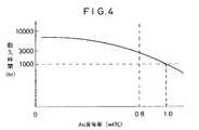
ここで、Auの含有率を0.03%以上、0.8%未満とする根拠について図4及び図5を参照しながら説明する。
【0086】
まず、図4は、第1の実施の形態に係る測定装置50Aを、装置温度600℃下であって、かつ、ディーゼルエンジンの排気ガス中で作動させた際の主ポンプセル68のインピーダンスが初期値の5倍になるまでの時間と、Au−Pt系合金電極の組成との関係を示すグラフであり、Au量が1%以上では合金電極が焼結し易くなり、主ポンプセルのインピーダンスが上昇することによって、高温での耐久性に欠けることを示している。
【0087】
更に、前記内側ポンプ電極64及び測定電極72をサーメットにて構成した場合においては、Au量を0.8%以上とした場合、電極の焼き付け工程で焼結による目詰まりが起こり易く、酸素ポンプとしての機能が低下するため、Au量は0.8%未満とすることが好ましい。
【0088】
次に、図5は、第1の実施の形態に係る測定装置50Aにおいて、第1室54内に設けられた内側ポンプ電極64及び測定電極72をAu−Pt系合金を含む電極とした場合に、装置温度680℃、酸素=0.3%、H2O=3%、NO=5000ppm、残りが窒素の混合ガスを測定した場合に、制御用酸素分圧検出セル76に発生する起電力V1と、測定用ポンプセル84に流れる電流Ip2との関係を示す。
【0089】
窒素酸化物の測定精度を高めるには、測定ポンプセル84のポンプ電流値Ip2に現れるオフセット成分(オフセット電流)をなるべく小さくする必要がある。この例では、オフセット電流をNO換算で1ppm以下にしたいため、制御用酸素分圧検出セル76における起電力V1を約250mV以上に設定する必要がある。しかし、図5に示す関係からわかるように、Au添加量が0.01%以下では、触媒活性が十分低下しないため、被測定ガス中に共存する酸素をNOの分解を伴わずに汲み出すのに必要な酸素濃淡電池起電力の領域(起電力V1≧250mVの領域)において、NOの分解が起こってしまい、正確な窒素酸化物の量を測定することが困難となる。従って、前記Au−Pt系合金中のAu量は0.01%以上、望ましくは0.03%以上とするのが好ましい。
【0090】
また、合金の主要成分である白金族元素としては、Pt、Rh等を用いることができ、特にPtとAuとの合金が低触媒活性の点で望ましい。
【0091】
次に、図6を参照しながら前記第1の実施の形態に係る測定装置50Aの変形例について説明する。なお、図2と対応するものについては同符号を付してその重複説明を省略する。
【0092】
この変形例に係る測定装置50Aaは、図6に示すように、前記第1の実施の形態に係る測定装置50A(図2参照)とほぼ同じ構成を有するが、全体として、ZrO2等の酸素イオン伝導性固体電解質を用いたセラミックスよりなる6枚の固体電解質層52a〜52fが積層されて構成され、下から1層目及び2層目が第1及び第2の基板層52f及び52eとされ、下から3層目及び5層目が第1及び第2のスペーサ層52d及び52bとされ、下から4層目及び6層目が第1及び第2の固体電解質層52c及び52aとされている点で異なる。
【0093】
更に、この変形例に係る測定装置50Aaは、第2の基板層52bと第1の固体電解質層52cとの間において、第1の固体電解質層52cの下面、第2の基板層52bの上面及び第1のスペーサ層52dの側面によって、基準ガス導入空間62が区画、形成されている。
【0094】
また、第1及び第2の固体電解質層52c及び52a間に第2のスペーサ層52bが挟設されると共に、第1及び第2の拡散律速部58及び60が挟設されている。
【0095】
そして、第2の固体電解質層52aの下面、第1及び第2の拡散律速部58及び60の側面並びに第1の固体電解質層52cの上面によって、被測定ガス中の酸素分圧を調整するための第1室54が区画、形成され、第2の固体電解質層52aの下面、第2の拡散律速部60の側面、第2のスペーサ層52bの側面並びに第1の固体電解質層52cの上面によって、被測定ガス中の酸素分圧を微調整し、更に被測定ガス中の酸化物、例えば窒素酸化物(NOx)を測定するための第2室56が区画、形成される。
【0096】
それ以外の構成並びに窒素酸化物の測定原理については、前記第1の実施の形態に係る測定装置50Aと同じであるため、ここではその重複説明を省略する。
【0097】
この変形例に係る測定装置50Aaは、第1の実施の形態に係る測定装置50Aと同様に、第1室54内に設けられた内側ポンプ電極64と測定電極72が、0.01%以上、1%未満のAuと、残部が主として白金族元素からなる合金を含むようにしているため、窒素酸化物の測定に際して妨害成分となる酸素を実質的にゼロとなるまで、かつ、窒素酸化物の測定に影響を及ぼすことなく排除することができ、測定用ポンプセル84及び電流計88を通じて被測定ガスに含まれる窒素酸化物を高精度に、かつ、安定に測定することができる。
【0098】
次に、図7を参照しながら第2の実施の形態に係る測定装置50Bについて説明する。なお、図6と対応するものについては同符号を付してその重複説明を省略する。
【0099】
この第2の実施の形態に係る測定装置50Bは、図7に示すように、前記変形例に係る測定装置50Aa(図6参照)とほぼ同じ構成を有するが、測定用ポンプセル84に代えて、測定用酸素分圧検出セル100が設けられている点で異なる。
【0100】
この測定用酸素分圧検出セル100は、第1の固体電解質層52cの上面のうち、前記第2室56を形づくる上面に形成された検出電極102と、前記第1の固体電解質層52cの下面に形成された前記基準電極74と、前記第1の固体電解質層52cによって構成されている。
【0101】
この場合、測定用酸素分圧検出セル100における検出電極102と基準電極74との間に、検出電極102の周りの雰囲気と基準電極74の周りの雰囲気との間の酸素濃度差に応じた起電力(酸素濃淡電池起電力)V2が発生することとなる。
【0102】
従って、前記検出電極102及び基準電極74間に発生する起電力(電圧)V2を電圧計104にて測定することにより、検出電極102の周りの雰囲気の酸素分圧、換言すれば、被測定ガス成分(NOx)の還元又は分解によって発生する酸素によって規定される酸素分圧が電圧値V2として検出される。
【0103】
前記起電力V2の変化の度合いが、NOx濃度を表すことになる。つまり、前記検出電極102と基準電極74と第1の固体電解質層52cとから構成される測定用酸素分圧検出セル100から出力される起電力V2が、被測定ガス中のNOx濃度を表すことになる。
【0104】
そして、この第2の実施の形態に係る測定装置50Bにおいても、第1の実施の形態に係る測定装置50Aと同様に、第1室54内に設けられた内側ポンプ電極64と測定電極72が、0.01%以上、1%未満のAuと、残部が主として白金族元素からなる合金を含むようにしているため、窒素酸化物の測定に際して妨害成分となる酸素を実質的にゼロとなるまで、かつ、窒素酸化物の測定に影響を及ぼすことなく排除することができ、測定用酸素分圧検出セル及び電圧計を通じて被測定ガスに含まれる窒素酸化物を高精度に、かつ、安定に測定することができる。
【0105】
次に、図8を参照しながら第3の実施の形態に係る測定装置50Cについて説明する。なお、図2と対応するものについては同符号を付してその重複説明を省略する。
【0106】
この第3の実施の形態に係る測定装置50Cは、図8に示すように、前記第1の実施の形態に係る測定装置50Aとほぼ同様の構成を有するが、検出電極82を被覆するように、第3の拡散律速部110を構成する多孔質Al2O3層あるいは多孔質ZrO3層が形成されている点と、補助ポンプセル112が設けられている点で異なる。
【0107】
この補助ポンプセル112は、前記第2の固体電解質層52aの下面のうち、前記第2室56を形づくる下面全面に形成された平面ほぼ矩形状の多孔質サーメット電極からなる補助ポンプ電極114と、前記基準電極74と、第2の固体電解質層52a、第2のスペーサ層52b及び第1の固体電解質層52cにて構成されている。
【0108】
前記補助ポンプ電極114は、前記主ポンプセル68における内側ポンプ電極64と同様に、被測定ガス中のNOx成分に対する還元能力を弱めた、あるいは還元能力のない材料を用いて構成するようにしている。この場合、0.01%以上、1%未満のAuと、残部が主として白金族元素からなる合金であって、より好ましくは、Au含有率が0.03%以上、0.8%未満の合金を含むようにしている。
【0109】
そして、前記補助ポンプセル112における補助ポンプ電極114と基準電極74間に、外部の電源116を通じて所望の一定電圧Vp3を印加することにより、第2室56内の雰囲気中の酸素を基準ガス導入空間62に汲み出せるようになっている。
【0110】
これによって、第2室56内の雰囲気の酸素分圧が、実質的に被測定ガス成分(NOx)が還元又は分解され得ない状況下で、かつ目的成分量の測定に実質的に影響がない低い酸素分圧値とされる。この場合、第1室54における主ポンプセル68の働きにより、この第2室56内に導入される酸素の量の変化は、被測定ガスの変化よりも大幅に縮小されるため、第2室56における酸素分圧は精度よく一定に制御される。
【0111】
また、この第3の実施の形態に係る測定装置50Cにおいては、前記定電圧(直流)電源86は、第3の拡散律速部110により制限されたNOxの流入下において、測定用ポンプセル84で分解時に生成した酸素のポンピングに対して限界電流を与える大きさの電圧を印加できるようになっている。
【0112】
従って、前記構成を有する第3の実施の形態に係る測定装置50Cにおいては、前記第2室56内において酸素分圧が制御された被測定ガスは、第3の拡散律速部110を通じて所定の拡散抵抗の下に、検出電極82に導かれることとなる。
【0113】
ところで、前記主ポンプセル68を動作させて第1室54内の雰囲気の酸素分圧をNOx測定に実質的に影響がない低い酸素分圧値に制御しようとしたとき、換言すれば、制御用酸素分圧検出セル76にて検出される電圧V1が一定となるように、フィードバック制御系80を通じて可変電源70のポンプ電圧Vp1を調整したとき、被測定ガス中の酸素濃度が大きく、例えば0〜20%に変化すると、通常、第2室56内の雰囲気及び検出電極82付近の雰囲気の各酸素分圧は、僅かに変化するようになる。これは、被測定ガス中の酸素濃度が高くなると、測定電極72上の第1室54の幅方向及び厚み方向に酸素濃度分布が生じ、この酸素濃度分布が被測定ガス中の酸素濃度により変化するためであると考えられる。
【0114】
しかし、この第3の実施の形態に係る測定装置50Cにおいては、第2室56に対して、その内部の雰囲気の酸素分圧を常に一定に低い酸素分圧値となるように、補助ポンプセル112を設けるようにしているため、第1室54から第2室56に導入される雰囲気の酸素分圧が被測定ガスの酸素濃度に応じて変化しても、前記補助ポンプセル112のポンプ動作によって、第2室56内の雰囲気の酸素分圧を常に一定の低い値とすることができ、その結果、NOxの測定に実質的に影響がない低い酸素分圧値に制御することができる。
【0115】
そして、検出電極82に導入された被測定ガスのNOxは、該検出電極82の周りにおいて還元又は分解されて、例えばNO→1/2N2+1/2O2の反応が引き起こされる。このとき、測定用ポンプセル84を構成する検出電極82と基準電極74との間には、酸素が第2室56から基準ガス導入空間62側に汲み出される方向に、所定の電圧Vp2、例えば430mV(700℃)が印加される。
【0116】
従って、測定用ポンプセル84に流れるポンプ電流Ip2は、第2室56に導かれる雰囲気中の酸素濃度、即ち、第2室56内の酸素濃度と検出電極82にてNOxが還元又は分解されて発生した酸素濃度との和に比例した値となる。
【0117】
この場合、第2室56内の雰囲気中の酸素濃度は、補助ポンプセル112にて一定に制御されていることから、前記測定用ポンプセル84に流れるポンプ電流Ip2は、NOxの濃度に比例することになる。また、このNOxの濃度は、第3の拡散律速部110にて制限されるNOxの拡散量に対応していることから、被測定ガスの酸素濃度が大きく変化したとしても、測定用ポンプセル84から電流計88を通じて正確にNOx濃度を測定することが可能となる。
【0118】
例えば、補助ポンプセル112にて制御された第2室56内の雰囲気の酸素分圧が0.02ppmで、被測定ガス中のNOx成分たるNO濃度が100ppmとすると、NOが還元又は分解されて発生する酸素濃度50ppmと第2室56内の雰囲気中の酸素濃度0.02ppmとの和(=50.02ppm)に相当するポンプ電流Ip2が流れることとなる。従って、測定用ポンプセル84におけるポンプ電流値Ip2は、NOxがほとんど還元又は分解された量を表し、そのため、被測定ガス中の酸素濃度に依存するようなこともない。
【0119】
次に、図9を参照しながら第4の実施の形態に係る測定装置50Dについて説明する。なお、図7及び図8と対応するものについては同符号を付してその重複説明を省略する。
【0120】
この第4の実施の形態に係る測定装置50Dは、図9に示すように、前記第2の実施の形態に係る測定装置50B(図7参照)とほぼ同様の構成を有するが、第3の実施の形態に係る測定装置50C(図8参照)と同じように、測定用酸素分圧検出セル100における検出電極102を被覆するように、第3の拡散律速部110を構成する多孔質Al2O3層あるいは多孔質ZrO3層が形成されている点と、補助ポンプセル112が設けられている点で異なる。
【0121】
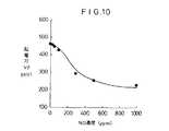
ここで、図10の特性図を参照しながら前記第4の実施の形態に係る測定装置50Dの検出原理を説明する。
【0122】
まず、外部空間のNO濃度が0ppmのとき、第1室54内の雰囲気中の酸素分圧が1.3×10⁻⁷atm、即ち、起電力V1=約300mVに保たれるように、主ポンプセル68におけるポンプ電圧Vp1を制御する。
【0123】
次に、補助ポンプセル112に印加される設定電圧Vp3を460mVに設定する。補助ポンプセル112の作用により、第2室56内の酸素分圧は、6.1×10⁻¹¹atmに制御され、その結果、前記測定用酸素分圧検出セル100における検出電極102と基準電極74との間の起電力V2は約460mVとなる。
【0124】
この場合、第2室56内の酸素分圧が6.1×10⁻¹¹atmであっても、第1室54内の酸素分圧が1.3×10⁻⁷atmであるため、可燃ガス成分は第1室54内で酸化され、NOx感度に影響しない。
【0125】
そして、外部空間のNO濃度が徐々に増加すると、前記検出電極102も上述した測定用ポンプセル84(図6参照)における検出電極82と同様に、NOx還元触媒として機能することから、前記検出電極102では、NOの還元又は分解反応が引き起こされ、該検出電極102の周りの雰囲気中の酸素濃度が上がり、これによって、検出電極102と基準電極74間に発生する起電力V2が徐々に低下することとなる。図10の特性図では、NO濃度が例えば300ppm、500ppm、1000ppmというように徐々に増加するにつれて、電圧計104にて検出される起電力V2は、300mV、250mV、220mVというように徐々に低下している。
【0126】
前記起電力V2の低下の度合いが、NO濃度を表すことになる。つまり、前記検出電極102と基準電極74と第1の固体電解質層52cとから構成される測定用酸素分圧検出セル100から出力される起電力V2が、被測定ガス中のNO濃度を表すことになる。
【0127】
この場合、前記第3の実施の形態に係る測定装置50Cと同様に、第2室56内の雰囲気の酸素分圧が、実質的に被測定ガス成分(NOx)が還元又は分解され得ない状況下で、かつ目的成分量の測定に実質的に影響がない低い酸素分圧値とされ、第1室54における主ポンプセル68の働きにより、この第2室56内に導入される酸素の量の変化は、被測定ガスの変化よりも大幅に縮小されるため、第2室56における酸素分圧は精度よく一定に制御される。
【0128】
従って、被測定ガスの酸素濃度が大きく変化したとしても、測定用酸素分圧検出セル100から電圧計104を通じて正確にNOx濃度を測定することが可能となる。
【0129】
前記第1〜第4の実施の形態に係る測定装置(変形例も含む)によれば、共存する水や炭酸ガス及び酸素の影響を排除して、長期間安定に測定することが可能であり、産業上極めて有用である。
【0130】
なお、この発明に係る窒素酸化物の測定装置は、上述の実施の形態に限らず、この発明の要旨を逸脱することなく、種々の構成を採り得ることはもちろんである。
【0131】
【発明の効果】
本発明の窒素酸化物の測定装置によれば、被測定ガス中の例えばNOx濃度を、酸素あるいはCO2、H2O等の影響を受けることなく、かつ、広い温度範囲において、長時間安定に測定可能となる。
【図面の簡単な説明】
【図1】第1の実施の形態に係る測定装置を示す平面図である。
【図2】図1におけるA−A線上の断面図である。
【図3】第1の実施の形態に係る測定装置における窒素酸化物の測定原理を示す説明図である。
【図4】第1の実施の形態に係る測定装置において、ディーゼルエンジンの排気ガス中での耐久性を示す特性図である。
【図5】第1の実施の形態に係る測定装置において、各組成の電極に対する主ポンプセルにおけるポンプ電圧と測定用ポンプセルにおけるポンプ電流との関係を示す特性図である。
【図6】第1の実施の形態に係る測定装置の変形例を示す断面図である。
【図7】第2の実施の形態に係る測定装置を示す断面図である。
【図8】第3の実施の形態に係る測定装置を示す断面図である。
【図9】第4の実施の形態に係る測定装置を示す断面図である。
【図10】第4の実施の形態に係る測定装置において、NO濃度の変化に対する測定用酸素分圧検出セルにて発生する起電力の変化を示す特性図である。
【図11】従来技術に係るガス分析装置の断面構成図である。
【符号の説明】
50A〜50D…測定装置 52a…第2の固体電解質層
52b…第2のスペーサ層 52c…第1の固体電解質層
52d…第2のスペーサ層 52e…第2の基板層
52f…第1の基板層 54…第1室
56…第2室 58…第1の拡散律速部
60…第2の拡散律速部 62…基準ガス導入空間
64…内側ポンプ電極 66…外側ポンプ電極
68…主ポンプセル 70…可変電源
72…測定電極 74…基準電極
76…制御用酸素分圧検出セル 82…検出電極
84…測定用ポンプセル 90…ヒータ
100…測定用酸素分圧検出セル 102…検出電極
110…第3の拡散律速部 112…補助ポンプセル
114…補助ポンプ電極[0001]
BACKGROUND OF THE INVENTION
The present invention relates to a nitrogen oxide measuring device for measuring nitrogen oxides contained in, for example, vehicle exhaust gas and the atmosphere. In the description of the metal composition, “%” means “% by weight” unless otherwise specified.
[0002]
[Prior art]
For example, in exhaust gas discharged from vehicles such as gasoline cars and diesel engine cars, nitrogen monoxide (NO), nitrogen dioxide (NO2) And other nitrogen oxides (NOx), carbon monoxide (CO), carbon dioxide (CO2), Water (H2O), hydrocarbon (HC), hydrogen (H2), Oxygen (O2) Etc. are included. In this case, NO accounts for about 80% of the total NOx, and NO and NO2Account for about 95% of the total NOx.
[0003]
Such a three-way catalyst that purifies HC, CO, and NOx contained in the exhaust gas exhibits the maximum purification efficiency near the theoretical air-fuel ratio (A / F = 14.6), and the A / F is 16 or more. When controlled, the amount of NOx generated decreases, but the purification efficiency of the catalyst decreases, and as a result, the amount of NOx discharged tends to increase.
[0004]
By the way, in recent years, CO for effective use of fossil fuels and prevention of global warming2There is an increasing market demand for reducing emissions, and there is a growing need to improve fuel efficiency to meet this demand. In response to such demands, for example, research on lean burn engines, research on NOx purification catalysts, and the like are being conducted, and among them, the need for NOx sensors is increasing.
[0005]
Conventionally, there is a NOx analyzer that detects such NOx. This NOx analyzer measures the characteristics unique to NOx using a chemiluminescence analysis method, but the apparatus itself is very large and has the disadvantage of being expensive. In addition, since optical system parts for detecting NOx are used, frequent maintenance is required. Furthermore, this NOx analyzer measures and measures NOx, and the detection element itself cannot be directly inserted into the fluid, so the situation frequently fluctuates, such as automobile exhaust gas. It is not suitable for analysis of transient phenomena.
[0006]
In order to solve these problems, a sensor has been proposed in which a desired gas component in exhaust gas is measured using a substrate made of an oxygen ion conductive solid electrolyte.
[0007]
FIG. 11 shows a configuration of a gas analyzer disclosed in International Publication WO95 / 30146. This apparatus includes a first chamber 4 into which a gas to be measured containing NO is introduced through a
[0008]
In the gas analyzer configured as described above, the partial pressure of oxygen contained in the gas to be measured introduced into the first chamber 4 through the
[0009]
On the other hand, O2The gas to be measured from which most of the gas is removed is introduced into the second chamber 8 through the pores 6. In the second chamber 8, the partial pressure of oxygen in the chamber is measured by detecting a potential difference generated between the measuring electrodes 14 a and 14 b with the
NO → (1/2) N2+ (1/2) O2
O is generated at that time2Is pumped out of the room by the
[0010]
[Problems to be solved by the invention]
By the way, at least the
[0011]
However, such an Au electrode alone or an alloy electrode containing Au is inferior in heat resistance, and if used for a long time, the electrode function is lowered by sintering, and there is a possibility that it cannot function sufficiently as an oxygen pump.
[0012]
The present invention has been made to eliminate the drawbacks of the conventional nitrogen oxide measuring apparatus, and the problem to be solved is that, for example, the concentration of NOx in the gas to be measured is changed to oxygen or CO.2, H2An object of the present invention is to provide a nitrogen oxide measuring device that can be measured stably for a long time without being affected by O or the like and in a wide temperature range.
[0013]
[Means for Solving the Problems]
BookThe nitrogen oxide measuring device according to the invention is:One sideExternal spaceIt was arranged on the introduction side of the gas to be measured fromHaving a pair of pump electrodes and pumping oxygen contained in the gas to be measured introduced from the external space on the basis of a control voltage applied between the pair of pump electrodes; A main pump means for controlling the oxygen partial pressure to a predetermined value at which NO cannot be decomposed, and a pair of detection electrodes provided on the introduction side of the gas to be measured after one is pumped by the main pump means And measuring pump means for pumping oxygen contained in the gas to be measured after being pumped by the main pump means based on a measuring voltage applied between the pair of detection electrodes And current detection means for detecting a pump current generated according to the amount of the oxygen pumped by the measurement pump means.CoatAt least one electrode exposed to the measurement gas processing spaceBut,0.03%that's all,0.8% Of Au and the balance mainly comprising platinum group elements.It is characterized byTo do.
[0014]
Thereby, first, oxygen is pumped by the main pump means in the gas to be measured introduced from the external space, and the oxygen is adjusted to a predetermined concentration. The gas to be measured whose oxygen concentration is adjusted by the main pump means is guided to the next measuring pump means. The measurement pump means pumps oxygen out of the gas to be measured based on a measurement voltage applied between the inner detection electrode and the outer detection electrode. The pump current generated in the measurement pump means is detected by the current detection means in accordance with the amount of oxygen pumped by the measurement pump means, whereby the oxide corresponding to the oxygen amount is measured.
[0015]
That is, in the measurement pump means, a voltage sufficient to decompose the nitrogen oxide is applied between the pair of detection electrodes, or the nitrogen oxide is decomposed into the measurement pump means. Install a cracking catalystIfThe oxygen generated from the nitrogen oxide decomposed by the voltage and / or the action of the nitrogen oxide decomposition catalyst is pumped, and the pump current generated thereby is detected by the current detection means, so that the amount of oxygen depends on the amount of oxygen. Oxide is measured.
[0016]
In particular, in the nitrogen oxide measuring apparatus according to the present invention, at least one electrode exposed to the processing space of the gas to be measured introduced from the external space,0.03%that's all,0.8% Of Au and the balance is made of an alloy mainly composed of platinum group elements. The electrode containing the alloy has extremely low activity as a decomposition catalyst for nitrogen oxides and does not decompose nitrogen oxides even under a low oxygen partial pressure. Can be eliminated without affecting the measurement of nitrogen oxides, and the nitrogen oxides contained in the gas to be measured can be accurately detected through the measurement pump means and the current detection means, and It can be measured stably.
[0017]
next,BookThe nitrogen oxide measuring device according to the invention is:One sideExternal spaceIt was arranged on the introduction side of the gas to be measured fromHaving a pair of pump electrodes and pumping oxygen contained in the gas to be measured introduced from the external space on the basis of a control voltage applied between the pair of pump electrodes; A main pump means for controlling the oxygen partial pressure to a predetermined value at which NO cannot be decomposed, and a pair of detection electrodes provided on the introduction side of the gas to be measured after one is pumped by the main pump means And is included in the gas to be measured after being pumped by the main pump means.Partial pressure of oxygen produced by the action of nitrogen oxide decomposition catalyst on oxide and oxygen contained in gas on the other detection electrode sideAccording to the differenceOxygen concentration cellA concentration detection unit that generates an electromotive force; and a voltage detection unit that detects the electromotive force generated by the concentration detection unit.CoatAt least one electrode exposed to the measurement gas processing spaceBut,0.03%that's all,0.8% Of Au and the balance mainly comprising platinum group elements.It is characterized byTo do.
[0018]
Thereby, first, oxygen is pumped by the main pump means in the gas to be measured introduced from the external space, and the oxygen is adjusted to a predetermined concentration. The gas to be measured whose oxygen concentration is adjusted by the main pump means is guided to the next concentration detecting means, and is contained in the gas to be measured after being pumped by the main pump means in the concentration detecting means. Oxygen concentration cell electromotive force is generated according to the difference between the amount of oxygen generated and the amount of oxygen contained in the gas on the other detection electrode side, and the electromotive force is detected by the voltage detection means. The corresponding nitrogen oxides are measured.
[0020]
In particular, in the nitrogen oxide measuring apparatus according to the present invention, at least one electrode exposed to the processing space of the gas to be measured introduced from the external space,0.03%that's all,0.8% Of Au and the balance is made of an alloy mainly composed of platinum group elements. The electrode containing the alloy has extremely low activity as a decomposition catalyst for nitrogen oxides and does not decompose nitrogen oxides even under a low oxygen partial pressure. Can be eliminated without affecting the measurement of nitrogen oxides, and the nitrogen oxides contained in the gas to be measured can be accurately detected through the measurement pump means and the current detection means, and It can be measured stably.
[0022]
PreviousWhen the electrode containing the alloy is composed of cermet, if the Au amount is 0.8% or more, clogging due to sintering is likely to occur in the electrode baking process, and the function as an oxygen pump is reduced. Is preferably less than 0.8%.
[0023]
Further, in order to improve the measurement accuracy of nitrogen oxides, it is necessary to reduce the offset component appearing in the detection value (current value or voltage value) of the measurement pump means or concentration detection means as much as possible, but the Au addition amount is 0.01 % Or less, the catalytic activity does not decrease sufficiently, so NO decomposition occurs within the range of the oxygen concentration cell electromotive force required to pump out oxygen present in the gas under measurement without decomposition of nitrogen oxides. As a result, it becomes difficult to accurately measure the amount of nitrogen oxides.
[0024]
Therefore, the Au content of the electrode containing the alloy is preferably 0.03% or more and less than 0.8%.
[0025]
Moreover, as a platinum group element which is a main component of the alloy, Pt, Rh, or the like can be used, and an alloy of Pt and Au is particularly desirable from the viewpoint of low catalytic activity.
[0026]
And in the said structure, one has a pair of measuring electrode arrange | positioned so as to oppose said one pump electrode in the said main pump means, And it is measured at the time of the pumping process in the said main pump means A concentration measuring means for measuring an oxygen concentration cell electromotive force generated according to a difference between the amount of oxygen contained in the gas and the amount of oxygen contained in the gas on the other measuring electrode side, and detected by the concentration measuring meansSaidThe main pump control means for adjusting the control voltage of the main pump means based on an electromotive force may be provided.Yes.
[0027]
Accordingly, in the concentration measuring unit, the difference between the amount of oxygen contained in the gas to be measured and the amount of oxygen contained in the gas on the other measuring electrode side during the pumping process by the main pump unit is determined. An electromotive force is generated. Then, the level of the control voltage applied between the pair of pump electrodes in the main pump means is adjusted based on the electromotive force through the main pump control means.
[0028]
The main pump means pumps oxygen in the gas to be measured introduced from the external space in an amount corresponding to the level of the control voltage. By supplying the level-adjusted control voltage to the main pump means, the oxygen concentration in the measurement gas is feedback-controlled to a predetermined level.
[0029]
Moreover, in the said structure, one pump electrode arrange | positioned at the introduction side of the said to-be-measured gas among the said pair of pump electrodes in the said main pump means is made from the inert material with low catalytic activity with respect to a nitrogen oxide. Preferred to configureYes.In this case, the decomposition action of nitrogen oxides on the one pump electrode is more preferably suppressed.
[0030]
In the above configuration, the auxiliary pump electrode is formed in the vicinity of the one detection electrode, and oxygen contained in the gas to be measured after being pumped by the main pump means is used as the auxiliary pump. An auxiliary pump means for performing the pumping process based on a voltage applied between the electrode and the other detection electrode may be provided.Yes.
[0031]
Thereby, first, the gas to be measured, in which the predetermined gas component is roughly adjusted to a predetermined concentration by the main pump means, is further finely adjusted by the auxiliary pump means.
[0032]
Generally, when the concentration of a predetermined gas component in the measurement gas in the external space changes greatly (for example, 0 to 20%), the concentration distribution of the predetermined gas component of the measurement gas led to the main pump means changes greatly, and the measurement The predetermined gas component amount led to the pump means or the concentration detection means also changes.
[0033]
At this time, the oxygen concentration in the gas to be measured after being pumped by the main pump means is finely adjusted by the pumping process by the auxiliary pump means. The change in oxygen concentration in the gas to be measured led to the auxiliary pump means is greatly reduced compared to the change in oxygen concentration in the gas to be measured from the external space (the gas to be measured led to the main pump means). The concentration of the predetermined gas component in the vicinity of one detection electrode in the pump means or in the vicinity of one detection electrode in the concentration detection means can be controlled accurately and constant.
[0034]
Therefore, the concentration of the predetermined gas component guided to the measuring pump means or the concentration detecting means is less affected by the change in oxygen concentration in the measured gas (measured gas guided to the main pump means), and as a result, The pump current value detected by the current detection means or the electromotive force detected by the voltage detection means is not affected by the concentration change of the predetermined gas component in the measured gas, and the amount of the target component present in the measured gas. The value corresponds exactly to.
[0035]
AndMentioned aboveIn the invention, the other measurement electrode is disposed at a position exposed in the space into which the reference gas is introduced.so,The oxygen contained in the gas to be measured can be compared with the oxygen contained in the reference gas, and the oxide can be detected more accurately.
[0036]
In particular, it is preferable to configure the other measurement electrode in common with the other detection electrode.Yes.In this case, the common electrode of the other measurement electrode in the concentration measurement means and the measurement pump means or the other detection electrode in the concentration detection means is exposed to the reference gas introduction space, and the concentration measurement means and the measurement pump means In accordance with this, one measurement electrode in the concentration measurement means and one detection electrode in the measurement pump means and one detection electrode in the concentration detection means can be respectively defined as the measurement electrode and the reference electrode in each detection process of the concentration detection means. It can be defined as a detection electrode.
[0037]
The main pump means is surrounded by a base made of a solid electrolyte, andOf the processing space,An inner pump electrode and an outer pump electrode formed inside and outside the first chamber into which the gas to be measured is introduced, and the base body sandwiched between these electrodes can be configured.The
[0038]
The measuring pump means is surrounded by a base made of a solid electrolyte, andOf the processing space,A reference electrode which is surrounded by a base made of a solid electrolyte and a detection electrode formed in a second chamber into which a gas to be measured after being pumped by the main pump means is introduced, and into which a reference gas is introduced A reference electrode formed in the introduction chamber, and the substrate sandwiched between the detection electrode and the reference electrode can be configured.The
[0039]
The concentration detecting means is surrounded by a base made of a solid electrolyte, andOf the processing space,A reference electrode which is surrounded by a base made of a solid electrolyte and a detection electrode formed in a second chamber into which a gas to be measured after being pumped by the main pump means is introduced, and into which a reference gas is introduced A reference electrode formed in the introduction chamber, and the substrate sandwiched between the detection electrode and the reference electrode can be configured.The
[0040]
The concentration measuring means is surrounded by a base made of a solid electrolyte, andOf the processing space,A measurement electrode formed in the first chamber into which the gas to be measured from the external space is introduced and a base made of a solid electrolyte, and formed in a reference gas introduction chamber into which the reference gas is introduced The reference electrode and the substrate sandwiched between the measurement electrode and the reference electrode can be configured.The
[0041]
Furthermore, in the above-described configuration, a first diffusion rate-determining unit that provides a predetermined diffusion resistance to the gas to be measured is provided in the introduction path of the gas to be measured to the first chamber in the external space, In the introduction path of the gas to be measured into the second chamber after being pumped by the pumping means, a second diffusion rate-limiting unit that gives a predetermined diffusion resistance to the gas to be measured is provided. MoyoYes.
[0042]
In addition, a third diffusion rate-determining unit that provides a predetermined diffusion resistance to the gas to be measured may be provided in an entry path of the gas to be measured to the detection electrode in the second chamber.Yes.
[0043]
Further, in the above configuration, a heating means for heating each of the substrates constituting the first chamber and the second chamber to a predetermined temperature may be provided.Yes.As a result, the nitrogen oxide detection operation is performed by heating the first chamber and the second chamber to a predetermined temperature by the heating means, so that the oxygen detection by the measurement pump means or the concentration detection means is highly accurate. To be done.
[0044]
As the solid electrolyte, ZrO2The oxygen ion conductive solid electrolyte using ceramics such as the above is suitable, and the first diffusion rate-limiting part or the second diffusion rate-limiting part is the desired gas state to be measured in the first chamber and the second chamber. In order to achieve this state, it is preferable to use a porous material that imparts a predetermined diffusion resistance to the gas to be measured.
[0045]
It is preferable to use Rh cermet as the nitrogen oxide decomposition catalyst constituting the electrode or catalyst disposed in the first chamber and the second chamber.The
[0046]
DETAILED DESCRIPTION OF THE INVENTION
Hereinafter, the nitrogen oxide measuring device according to the present invention includes NO, NO contained in, for example, vehicle exhaust gas and the atmosphere.2Several embodiments applied to a nitrogen oxide measuring apparatus for measuring nitrogen oxides will be described with reference to FIGS.
[0047]
First, as shown in FIGS. 1 and 2, the measuring
[0048]
Specifically, the
[0049]
A
[0050]
In addition, a through hole (first diffusion rate-determining part) for communicating the external space to be measured with gas and the
[0051]
A
[0052]
A space (for example, the atmosphere) into which a reference gas for measuring oxide is introduced is introduced by the lower surface of the second
[0053]
That is, in the
[0054]
Here, the first and second diffusion rate-limiting
[0055]
In particular, the second diffusion
[0056]
In addition, an
[0057]
Then, a desired control voltage (pump voltage)
[0058]
In addition, among the upper surfaces of the first
[0059]
The control oxygen partial
[0060]
That is, the voltage V1 generated between the
V1 = RT / 4F · ln (P1 (O2) / P0 (O2))
R: Gas constant
T: Absolute temperature
F: Faraday number
P1 (O2): Oxygen partial pressure in the
P0 (O2): Oxygen partial pressure of the reference gas
Have the relationship. Therefore, by measuring the voltage V1 based on the Nernst equation with a
[0061]
The detected oxygen partial pressure value is used to control the pump voltage of the
[0062]
Further, in the measuring
[0063]
The
[0064]
In the
[0065]
Further, in the measuring
[0066]
As shown in FIG. 2, the
[0067]
For example, when the gas temperature of the gas to be measured changes between 300 ° C. and 850 ° C., the
[0068]
In particular, in the
[0069]
Further, when an alloy of Au and a platinum group element is included in the electrode material, it is desirable to include an alloy of 0.01% or more and less than 1% Au and the balance mainly consisting of the platinum group element, more preferably, The Au content of the alloy is set to 0.03% or more and less than 0.8%.
[0070]
Au and platinum group elements may be pre-alloyed in an alloy powder and baked as a cermet, and a small amount of Au is attached to an electrode made of only Pt by a method such as electroless plating. It may be alloyed by aging or by thermal diffusion during use.
The measuring
[0071]
Prior to the measurement of the oxide, the
[0072]
Next, measurement of oxides such as NOx contained in the measurement gas is started by introducing the measurement gas into the
[0073]
The gas to be measured introduced into the
[0074]
This voltage V1 is the oxygen concentration cell electromotive force defined by the Nernst equation described above, and the pump voltage Vp1 of the
[0075]
Further, in the
[0076]
This is because NOx in the gas to be measured (atmosphere) is N in the first chamber 54.2And O2This is because the NOx in the
[0077]
The gas to be measured, which is controlled to have a predetermined oxygen partial pressure in the
[0078]
In the
[0079]
Here, the measurement principle of the
[0080]
In FIG. 3, the gas to be measured is introduced into the
[0081]
Then, the atmosphere in the
[0082]
In this method, the NOx concentration: Cn is obtained by Cn = k · Ip2-A. However, k is a sensitivity coefficient, Ip2 is a current value flowing through the
[0083]
Most of the Ip2 is due to oxygen generated by decomposition of the NOx component in the gas to be measured. Compared with the conventional method, the Ip2 is in a state where a small amount of oxygen is excluded. It is possible to measure accurately up to NOx. The
[0084]
Thus, in the measuring
[0085]
Here, the grounds for setting the Au content to be 0.03% or more and less than 0.8% will be described with reference to FIGS.
[0086]
First, FIG. 4 shows that the impedance of the
[0087]
Further, in the case where the
[0088]
Next, FIG. 5 illustrates a case where the
[0089]
In order to increase the measurement accuracy of nitrogen oxides, it is necessary to make the offset component (offset current) appearing in the pump current value Ip2 of the
[0090]
Moreover, as a platinum group element which is a main component of the alloy, Pt, Rh, or the like can be used, and an alloy of Pt and Au is particularly desirable from the viewpoint of low catalytic activity.
[0091]
Next, a modification of the
[0092]
As shown in FIG. 6, the measuring apparatus 50Aa according to this modification has substantially the same configuration as the measuring
[0093]
Furthermore, the measuring apparatus 50Aa according to this modification includes a lower surface of the first
[0094]
Further, the
[0095]
In order to adjust the partial pressure of oxygen in the gas to be measured by the lower surface of the second
[0096]
Since the rest of the configuration and the measurement principle of nitrogen oxides are the same as those of the
[0097]
As with the
[0098]
Next, a measuring
[0099]
As shown in FIG. 7, the measuring
[0100]
The measurement oxygen partial
[0101]
In this case, an oxygen concentration difference between the atmosphere around the
[0102]
Therefore, by measuring the electromotive force (voltage) V2 generated between the
[0103]
The degree of change in the electromotive force V2 represents the NOx concentration. That is, the electromotive force V2 output from the measurement oxygen partial
[0104]
And also in the measuring
[0105]
Next, a measurement apparatus 50C according to the third embodiment will be described with reference to FIG. 2 corresponding to those in FIG. 2 are denoted by the same reference numerals, and redundant description thereof is omitted.
[0106]
As shown in FIG. 8, the measurement apparatus 50C according to the third embodiment has substantially the same configuration as the
[0107]
The
[0108]
Similar to the
[0109]
Then, a desired constant voltage Vp3 is applied between the
[0110]
As a result, the oxygen partial pressure of the atmosphere in the
[0111]
In the measuring apparatus 50C according to the third embodiment, the constant voltage (direct current)
[0112]
Therefore, in the measuring apparatus 50C according to the third embodiment having the above-described configuration, the gas to be measured whose oxygen partial pressure is controlled in the
[0113]
By the way, when the
[0114]
However, in the measuring apparatus 50C according to the third embodiment, the
[0115]
The NOx of the gas to be measured introduced into the
[0116]
Accordingly, the pump current Ip2 flowing through the
[0117]
In this case, since the oxygen concentration in the atmosphere in the
[0118]
For example, if the oxygen partial pressure of the atmosphere in the
[0119]
Next, a measuring
[0120]
As shown in FIG. 9, the measuring
[0121]
Here, the detection principle of the
[0122]
First, when the NO concentration in the external space is 0 ppm, the oxygen partial pressure in the atmosphere in the
[0123]
Next, the set voltage Vp3 applied to the
[0124]
In this case, the oxygen partial pressure in the
[0125]
When the NO concentration in the external space gradually increases, the
[0126]
The degree of decrease in the electromotive force V2 represents the NO concentration. That is, the electromotive force V2 output from the measurement oxygen partial
[0127]
In this case, as in the measurement apparatus 50C according to the third embodiment, the oxygen partial pressure of the atmosphere in the
[0128]
Therefore, even if the oxygen concentration of the gas to be measured changes greatly, the NOx concentration can be accurately measured from the measuring oxygen partial
[0129]
According to the measurement apparatus (including modifications) according to the first to fourth embodiments, it is possible to stably measure for a long period of time by eliminating the influence of coexisting water, carbon dioxide gas and oxygen. It is extremely useful in industry.
[0130]
The nitrogen oxide measuring device according to the present invention is not limited to the above-described embodiment, and it goes without saying that various configurations can be adopted without departing from the gist of the present invention.
[0131]
【The invention's effect】
According to the nitrogen oxide measuring apparatus of the present invention, for example, the NOx concentration in the gas to be measured is changed to oxygen or CO 2.2, H2Measurement can be performed stably for a long time without being affected by O or the like and in a wide temperature range.
[Brief description of the drawings]
FIG. 1 is a plan view showing a measuring apparatus according to a first embodiment.
FIG. 2 is a cross-sectional view taken along line AA in FIG.
FIG. 3 is an explanatory diagram showing the measurement principle of nitrogen oxides in the measuring apparatus according to the first embodiment.
FIG. 4 is a characteristic diagram showing durability in the exhaust gas of a diesel engine in the measuring apparatus according to the first embodiment.
FIG. 5 is a characteristic diagram showing the relationship between the pump voltage in the main pump cell and the pump current in the measurement pump cell with respect to the electrodes of each composition in the measuring apparatus according to the first embodiment.
FIG. 6 is a cross-sectional view showing a modification of the measuring apparatus according to the first embodiment.
FIG. 7 is a cross-sectional view showing a measuring apparatus according to a second embodiment.
FIG. 8 is a cross-sectional view showing a measuring apparatus according to a third embodiment.
FIG. 9 is a cross-sectional view showing a measuring apparatus according to a fourth embodiment.
FIG. 10 is a characteristic diagram showing a change in electromotive force generated in a measurement oxygen partial pressure detection cell with respect to a change in NO concentration in the measurement apparatus according to the fourth embodiment.
FIG. 11 is a cross-sectional configuration diagram of a gas analyzer according to a conventional technique.
[Explanation of symbols]
50A to 50D ... Measuring
52b ...
52d ...
52f ...
56 ...
60 ... Second
64 ...
68 ...
72 ...
76 ... oxygen partial pressure detection cell for
84 ...
100 ... oxygen partial pressure detection cell for
110: Third diffusion control unit 112: Auxiliary pump cell
114 ... Auxiliary pump electrode
Claims (15)
Translated fromJapanese一方が、前記主ポンプ手段にてポンピング処理された後の被測定ガスの導入側に設けられた一対の検出電極を有し、かつ、前記主ポンプ手段にてポンピング処理された後の被測定ガスに含まれる酸素を、前記一対の検出電極間に印加される測定用電圧に基づいてポンピング処理する測定用ポンプ手段と、
前記測定用ポンプ手段によりポンピング処理される前記酸素の量に応じて生じるポンプ電流を検出する電流検出手段とを具備し、
前記被測定ガスの処理空間に露呈する少なくとも一つの電極が、0.03%以上、0.8%未満のAuと、残部が主として白金族元素からなる合金を含むことを特徴とする窒素酸化物の測定装置。One has a pair of pump electrodes disposed on the introduction side of the gas to be measured from the external space, and oxygen contained in the gas to be measured introduced from the external space is transferred between the pair of pump electrodes. Main pump means for controlling the oxygen partial pressure in the processing atmosphere to a predetermined value at which NO cannot be decomposed by pumping based on a control voltage applied to
One of the gas to be measured having a pair of detection electrodes provided on the introduction side of the gas to be measured after being pumped by the main pump means and having been pumped by the main pump means Measuring pump means for pumping oxygen contained in the gas based on a measuring voltage applied between the pair of detection electrodes;
Current detecting means for detecting a pump current generated according to the amount of oxygen pumped by the measuring pump means;
At least one electrode is0.03% or more, of nitrogen oxides, which comprises a less than0.8% Au, the alloy and the balance being mainly a platinum group element which is exposed to the process space priorSymbol measurement gas Measuring device for things.
前記測定用ポンプ手段は、前記一対の検出電極間に窒素酸化物を分解するのに十分な電圧を印加し、あるいは該測定用ポンプ手段に配設された窒素酸化物分解触媒のいずれか、あるいは両方の作用によって生成した酸素を、前記一対の検出電極間に印加される前記測定用電圧に基づいてポンピング処理することを特徴とする窒素酸化物の測定装置。In the measuring device of nitrogen oxides according to claim 1,
The measurement pump means applies a voltage sufficient for decomposing nitrogen oxides between the pair of detection electrodes, or one of the nitrogen oxide decomposition catalysts disposed in the measurement pump means, or An apparatus for measuring nitrogen oxides, wherein oxygen generated by both actions is pumped based on the measurement voltage applied between the pair of detection electrodes.
一方が、前記主ポンプ手段にてポンピング処理された後の被測定ガスの導入側に設けられた一対の検出電極を有し、かつ、前記主ポンプ手段にてポンピング処理された後の被測定ガスに含まれる酸化物に対する窒素酸化物分解触媒の作用によって生成された酸素と他方の検出電極側のガスに含まれる酸素との分圧差に応じた酸素濃淡電池起電力を発生する濃度検出手段と、
前記濃度検出手段により発生する前記起電力を検出する電圧検出手段とを具備し、
前記被測定ガスの処理空間に露呈する少なくとも一つの電極が、0.03%以上、0.8%未満のAuと、残部が主として白金族元素からなる合金を含むことを特徴とする窒素酸化物の測定装置。One has a pair of pump electrodes disposed on the introduction side of the gas to be measured from the external space, and oxygen contained in the gas to be measured introduced from the external space is transferred between the pair of pump electrodes. Main pump means for controlling the oxygen partial pressure in the processing atmosphere to a predetermined value at which NO cannot be decomposed by pumping based on a control voltage applied to
One of the gas to be measured having a pair of detection electrodes provided on the introduction side of the gas to be measured after being pumped by the main pump means and having been pumped by the main pump means and concentration detection means for generatingoxygen concentration cell electromotive force corresponding to apartial pressure differencebetween the oxygen contained in the gas produced oxygen and other detection electrode side by the action of the nitrogen oxide decomposing catalyst to the oxide contained in the ,
Voltage detecting means for detecting the electromotive force generated by the concentration detecting means,
At least one electrode is0.03% or more, of nitrogen oxides, which comprises a less than0.8% Au, the alloy and the balance being mainly a platinum group element which is exposed to the process space priorSymbol measurement gas Measuring device for things.
一方が、前記主ポンプ手段における前記一方のポンプ電極と対向するように配設された一対の測定電極を有し、かつ、前記主ポンプ手段でのポンピング処理時における被測定ガスに含まれる酸素の量と他方の測定電極側のガスに含まれる酸素の量との差に応じて生じる酸素濃淡電池起電力を測定する濃度測定手段と、
前記濃度測定手段にて検出された前記起電力に基づいて前記主ポンプ手段の前記制御電圧を調整する主ポンプ制御手段が設けられていることを特徴とする窒素酸化物の測定装置。In the measuring device of nitrogen oxides according to any one of claims 1 to3 ,
One has a pair of measurement electrodes arranged to face the one pump electrode in the main pump means, and oxygen contained in the gas to be measured during the pumping process in the main pump means Concentration measuring means for measuring an oxygen concentration cell electromotive force generated according to a difference between the amount and the amount of oxygen contained in the gas on the other measurement electrode side;
Measuring apparatus of nitrogen oxides, characterized in that the main pumping control means for adjusting the control voltage of said main pumping means onthe basis ofthe electromotive force detected by said concentration-measuring means.
前記一方の検出電極の近傍に形成された補助ポンプ電極を有し、かつ、前記主ポンプ手段にてポンピング処理された後の被測定ガスに含まれる酸素を、前記補助ポンプ電極と前記他方の検出電極間に印加される電圧に基づいて前記ポンピング処理する補助ポンプ手段が設けられていることを特徴とする窒素酸化物の測定装置。In the measuring device of nitrogen oxides according to any one of claims 1 to4 ,
It has an auxiliary pump electrode formed in the vicinity of the one detection electrode, and oxygen contained in the gas to be measured after being pumped by the main pump means detects the auxiliary pump electrode and the other detection electrode. An apparatus for measuring nitrogen oxides, comprising auxiliary pump means for performing the pumping process based on a voltage applied between electrodes.
前記他方の測定電極は、基準ガスが導入される空間に露呈する位置に配設されていることを特徴とする窒素酸化物の測定装置。In the measuring device of nitrogen oxides according to any one of claims 1 to5 ,
2. The nitrogen oxide measuring device according to claim 1, wherein the other measuring electrode is disposed at a position exposed to a space into which the reference gas is introduced.
前記他方の測定電極は、前記他方の検出電極と共通に構成されていることを特徴とする窒素酸化物の測定装置。In the measuring device of nitrogen oxides according to any one of claims 1 to6 ,
2. The nitrogen oxide measuring apparatus according to claim 1, wherein the other measuring electrode is configured in common with the other detecting electrode.
前記主ポンプ手段は、固体電解質からなる基体にて囲まれ、かつ、前記処理空間のうち、前記被測定ガスが導入される第1室の内外に形成された内側ポンプ電極及び外側ポンプ電極と、
これら両電極にて挟まれた前記基体を有することを特徴とする窒素酸化物の測定装置。In the measuring device of nitrogen oxides according to any one of claims 1 to7 ,
The main pump means is surrounded by a substrate made of a solid electrolyte, and an inner pump electrode and an outer pump electrode formed inside and outside the first chamber into which the gas to be measured is introduced in theprocessing space ,
An apparatus for measuring nitrogen oxide, comprising the substrate sandwiched between these two electrodes.
固体電解質からなる基体にて囲まれ、かつ基準ガスが導入される基準ガス導入室に形成された基準電極と、
前記検出電極と前記基準電極にて挟まれた前記基体を有することを特徴とする窒素酸化物の測定装置。According to claim 1, the measuring apparatus of nitrogen oxides according to any one of4-8, wherein the measuring pumping means is surrounded by substrates composed of solid electrolytes,and, among the processing space, A detection electrode formed in a second chamber into which a gas to be measured after being pumped by the main pump means is introduced;
A reference electrode surrounded by a substrate made of a solid electrolyte and formed in a reference gas introduction chamber into which a reference gas is introduced;
An apparatus for measuring nitrogen oxide, comprising: the substrate sandwiched between the detection electrode and the reference electrode.
前記濃度検出手段は、固体電解質からなる基体にて囲まれ、かつ、前記処理空間のうち、前記主ポンプ手段にてポンピング処理された後の被測定ガスが導入される第2室内に形成された検出電極と、
固体電解質からなる基体にて囲まれ、かつ基準ガスが導入される基準ガス導入室に形成された前記基準電極と、
前記検出電極と前記基準電極にて挟まれた前記基体を有することを特徴とする窒素酸化物の測定装置。In the measuring device of nitrogen oxides according to any one of claims 3 to8 ,
The concentration detection means is surrounded by a base made of a solid electrolyte, and is formed in a second chamber of theprocessing space into which a gas to be measured after being pumped by the main pump means is introduced. A sensing electrode;
The reference electrode surrounded by a base made of a solid electrolyte and formed in a reference gas introduction chamber into which a reference gas is introduced;
An apparatus for measuring nitrogen oxide, comprising: the substrate sandwiched between the detection electrode and the reference electrode.
前記濃度測定手段は、固体電解質からなる基体にて囲まれ、かつ、前記処理空間のうち、前記外部空間からの被測定ガスが導入される第1室内に形成された測定電極と、
固体電解質からなる基体にて囲まれ、かつ基準ガスが導入される基準ガス導入室に形成された前記基準電極と、
前記測定電極と前記基準電極にて挟まれた前記基体を有することを特徴とする窒素酸化物の測定装置。In the measuring device of nitrogen oxides according to any one of claims4 to10 ,
It said density measuring device is surrounded by substrates composed of solid electrolytes,and, among the processing space, and a measuring electrode measurement gas from the external space is formed in thefirst chamberthat will be introduced,
The reference electrode surrounded by a base made of a solid electrolyte and formed in a reference gas introduction chamber into which a reference gas is introduced;
An apparatus for measuring nitrogen oxide, comprising: the substrate sandwiched between the measurement electrode and the reference electrode.
前記外部空間における前記被測定ガスの前記第1室への導入経路に、前記被測定ガスに対して所定の拡散抵抗を付与する第1の拡散律速部が設けられ、
前記主ポンプ手段にてポンピング処理された後の前記被測定ガスの前記第2室への導入経路に、前記被測定ガスに対して所定の拡散抵抗を付与する第2の拡散律速部が設けられていることを特徴とする窒素酸化物の測定装置。In the measurement apparatus of the nitrogen oxide according to any one of claims8-11,
A first diffusion rate-determining section that provides a predetermined diffusion resistance to the gas to be measured is provided in the introduction path of the gas to be measured to the first chamber in the external space;
A second diffusion rate-determining unit that provides a predetermined diffusion resistance to the gas to be measured is provided in the introduction path of the gas to be measured to the second chamber after being pumped by the main pump unit. An apparatus for measuring nitrogen oxides.
前記第2室における前記被測定ガスの前記検出電極への進入経路に、前記被測定ガスに対して所定の拡散抵抗を付与する第3の拡散律速部が設けられていることを特徴とする窒素酸化物の測定装置。In the measuring device of nitrogen oxides according to any one of claims9 to12 ,
Nitrogen, characterized in that a third diffusion rate-determining part for providing a predetermined diffusion resistance to the gas to be measured is provided in an entry path of the gas to be measured to the detection electrode in the second chamber. Oxide measuring device.
前記第1室及び前記第2室を構成する前記各基体を所定温度に加熱する加熱手段を有することを特徴とする窒素酸化物の測定装置。In the nitrogen oxide measuring apparatus according to any one of claims9 to13 ,
An apparatus for measuring nitrogen oxide, comprising heating means for heating each of the substrates constituting the first chamber and the second chamber to a predetermined temperature.
前記窒素酸化物分解触媒はRhサーメットであることを特徴とする窒素酸化物の測定装置。In the measuring device of nitrogen oxides according to any one of claims 2 to14 ,
The nitrogen oxide decomposing catalyst is Rh cermet, and the nitrogen oxide measuring apparatus is characterized in that:
Priority Applications (3)
| Application Number | Priority Date | Filing Date | Title |
|---|---|---|---|
| JP02557697AJP3619344B2 (en) | 1996-02-23 | 1997-02-07 | Nitrogen oxide measuring device |
| DE69733509TDE69733509T2 (en) | 1996-02-23 | 1997-02-24 | Sensor arrangement for the determination of nitrogen oxides |
| EP19970301197EP0791825B1 (en) | 1996-02-23 | 1997-02-24 | Sensing device for measuring nitrogen oxides |
Applications Claiming Priority (3)
| Application Number | Priority Date | Filing Date | Title |
|---|---|---|---|
| JP8-36753 | 1996-02-23 | ||
| JP3675396 | 1996-02-23 | ||
| JP02557697AJP3619344B2 (en) | 1996-02-23 | 1997-02-07 | Nitrogen oxide measuring device |
Publications (2)
| Publication Number | Publication Date |
|---|---|
| JPH09288086A JPH09288086A (en) | 1997-11-04 |
| JP3619344B2true JP3619344B2 (en) | 2005-02-09 |
Family
ID=26363212
Family Applications (1)
| Application Number | Title | Priority Date | Filing Date |
|---|---|---|---|
| JP02557697AExpired - LifetimeJP3619344B2 (en) | 1996-02-23 | 1997-02-07 | Nitrogen oxide measuring device |
Country Status (3)
| Country | Link |
|---|---|
| EP (1) | EP0791825B1 (en) |
| JP (1) | JP3619344B2 (en) |
| DE (1) | DE69733509T2 (en) |
Families Citing this family (15)
| Publication number | Priority date | Publication date | Assignee | Title |
|---|---|---|---|---|
| JP3544437B2 (en)* | 1996-09-19 | 2004-07-21 | 日本碍子株式会社 | Gas sensor |
| DE69703018T2 (en) | 1996-12-02 | 2001-05-03 | Ngk Spark Plug Co., Ltd. | Method and device for measuring nitrogen oxide concentration |
| US6695964B1 (en) | 1996-12-02 | 2004-02-24 | Ngk Spark Plug Co., Ltd. | Method and apparatus for measuring NOx gas concentration |
| US20020011409A1 (en)* | 1998-09-18 | 2002-01-31 | Satoshi Sugaya | Gas sensor |
| JP3916945B2 (en) | 2001-12-12 | 2007-05-23 | 株式会社デンソー | Gas sensor element |
| JP3979240B2 (en) | 2002-09-13 | 2007-09-19 | 株式会社デンソー | Gas concentration detector |
| EP2058653A4 (en)* | 2006-09-29 | 2012-12-26 | Ngk Insulators Ltd | Gas sensor element treatment method |
| JP2009244140A (en)* | 2008-03-31 | 2009-10-22 | Ngk Insulators Ltd | GAS SENSOR AND NOx SENSOR |
| JP5081772B2 (en)* | 2008-09-15 | 2012-11-28 | 株式会社日本自動車部品総合研究所 | Method for manufacturing gas sensor element |
| JP6346524B2 (en)* | 2014-08-29 | 2018-06-20 | 日本碍子株式会社 | Gas sensor and method for forming gas inlet in gas sensor |
| CN111896591A (en)* | 2020-08-04 | 2020-11-06 | 北京致感致联科技有限公司 | Self-calibration gas sensor device and calibration method and system thereof |
| CN114646683B (en)* | 2020-12-18 | 2024-04-23 | 江苏惟哲新材料有限公司 | Ceramic humidity sensor |
| CN114689651B (en)* | 2020-12-31 | 2024-10-22 | 长城汽车股份有限公司 | Nitrogen-oxygen sensor, nitrogen oxide measuring method and vehicle |
| CN115112740B (en)* | 2022-01-04 | 2024-05-10 | 长城汽车股份有限公司 | Sensor for monitoring ammonia content and method for monitoring ammonia content in tail gas |
| CN115876856B (en)* | 2022-12-01 | 2024-11-22 | 长城汽车股份有限公司 | Ammonia and nitrogen oxide co-detection system, method and vehicle in engine exhaust |
Family Cites Families (8)
| Publication number | Priority date | Publication date | Assignee | Title |
|---|---|---|---|---|
| JPH0672861B2 (en)* | 1986-08-04 | 1994-09-14 | 日本碍子株式会社 | NOx sensor |
| JP2636883B2 (en)* | 1988-04-30 | 1997-07-30 | 日本碍子株式会社 | NOx concentration measuring device |
| US5034112A (en)* | 1988-05-19 | 1991-07-23 | Nissan Motor Company, Ltd. | Device for measuring concentration of nitrogen oxide in combustion gas |
| US5217588A (en)* | 1992-02-27 | 1993-06-08 | Gte Laboratories Incorporated | Method and apparatus for sensing NOx |
| JP2885336B2 (en)* | 1994-04-21 | 1999-04-19 | 日本碍子株式会社 | Method and apparatus for measuring NOx concentration in gas to be measured |
| GB2288873A (en)* | 1994-04-28 | 1995-11-01 | Univ Middlesex Serv Ltd | Multi-component gas analysis apparatus |
| DE4439901C2 (en)* | 1994-11-08 | 1998-01-15 | Bosch Gmbh Robert | Electrochemical sensor for the determination of nitrogen oxides in gas mixtures |
| JP3450084B2 (en)* | 1995-03-09 | 2003-09-22 | 日本碍子株式会社 | Method and apparatus for measuring combustible gas components |
- 1997
- 1997-02-07JPJP02557697Apatent/JP3619344B2/ennot_activeExpired - Lifetime
- 1997-02-24DEDE69733509Tpatent/DE69733509T2/ennot_activeExpired - Lifetime
- 1997-02-24EPEP19970301197patent/EP0791825B1/ennot_activeExpired - Lifetime
Also Published As
| Publication number | Publication date |
|---|---|
| EP0791825B1 (en) | 2005-06-15 |
| DE69733509T2 (en) | 2006-05-11 |
| JPH09288086A (en) | 1997-11-04 |
| EP0791825A1 (en) | 1997-08-27 |
| DE69733509D1 (en) | 2005-07-21 |
Similar Documents
| Publication | Publication Date | Title |
|---|---|---|
| JP3671100B2 (en) | Oxide sensor | |
| JP3610182B2 (en) | Gas sensor | |
| JP3488591B2 (en) | Oxide sensor | |
| JP3537983B2 (en) | Gas sensor | |
| JP3701124B2 (en) | Gas sensor and nitrogen oxide sensor | |
| US5939615A (en) | Method of measuring a gas component and sensing device for measuring the gas component | |
| JP2885336B2 (en) | Method and apparatus for measuring NOx concentration in gas to be measured | |
| JP3623065B2 (en) | Nitrogen oxide sensor | |
| JP3619344B2 (en) | Nitrogen oxide measuring device | |
| JP3647181B2 (en) | Nitrogen oxide measurement method | |
| JP3631582B2 (en) | Gas sensor | |
| JPWO2008007706A1 (en) | Gas sensor and nitrogen oxide sensor | |
| JP3623066B2 (en) | Gas sensor | |
| JP3860590B2 (en) | Gas sensor and nitrogen oxide sensor | |
| JP3664558B2 (en) | Gas sensor | |
| JP4165652B2 (en) | Gas sensor | |
| JP3771569B2 (en) | NOx sensor | |
| JP3511468B2 (en) | Measuring method of NOx concentration in measured gas | |
| US20050235631A1 (en) | Sensor element for a sensor for determining the oxygen concentration in the exhaust gas of internal combustion engines | |
| JP3798412B2 (en) | NOx sensor | |
| JP3571039B2 (en) | Measurement device for NOx concentration in gas to be measured | |
| JP3756123B2 (en) | NOx sensor and method for measuring NOx concentration |
Legal Events
| Date | Code | Title | Description |
|---|---|---|---|
| A131 | Notification of reasons for refusal | Free format text:JAPANESE INTERMEDIATE CODE: A131 Effective date:20040810 | |
| A521 | Written amendment | Free format text:JAPANESE INTERMEDIATE CODE: A523 Effective date:20041007 | |
| TRDD | Decision of grant or rejection written | ||
| A01 | Written decision to grant a patent or to grant a registration (utility model) | Free format text:JAPANESE INTERMEDIATE CODE: A01 Effective date:20041109 | |
| A61 | First payment of annual fees (during grant procedure) | Free format text:JAPANESE INTERMEDIATE CODE: A61 Effective date:20041112 | |
| R150 | Certificate of patent or registration of utility model | Free format text:JAPANESE INTERMEDIATE CODE: R150 | |
| FPAY | Renewal fee payment (event date is renewal date of database) | Free format text:PAYMENT UNTIL: 20081119 Year of fee payment:4 | |
| FPAY | Renewal fee payment (event date is renewal date of database) | Free format text:PAYMENT UNTIL: 20081119 Year of fee payment:4 | |
| FPAY | Renewal fee payment (event date is renewal date of database) | Free format text:PAYMENT UNTIL: 20091119 Year of fee payment:5 | |
| FPAY | Renewal fee payment (event date is renewal date of database) | Free format text:PAYMENT UNTIL: 20101119 Year of fee payment:6 | |
| FPAY | Renewal fee payment (event date is renewal date of database) | Free format text:PAYMENT UNTIL: 20101119 Year of fee payment:6 | |
| FPAY | Renewal fee payment (event date is renewal date of database) | Free format text:PAYMENT UNTIL: 20111119 Year of fee payment:7 | |
| FPAY | Renewal fee payment (event date is renewal date of database) | Free format text:PAYMENT UNTIL: 20111119 Year of fee payment:7 | |
| FPAY | Renewal fee payment (event date is renewal date of database) | Free format text:PAYMENT UNTIL: 20121119 Year of fee payment:8 | |
| FPAY | Renewal fee payment (event date is renewal date of database) | Free format text:PAYMENT UNTIL: 20131119 Year of fee payment:9 | |
| EXPY | Cancellation because of completion of term |