JP3619176B2 - Aerosol particle sorting device and inhaler - Google Patents
Aerosol particle sorting device and inhalerDownload PDFInfo
- Publication number
- JP3619176B2 JP3619176B2JP2001278974AJP2001278974AJP3619176B2JP 3619176 B2JP3619176 B2JP 3619176B2JP 2001278974 AJP2001278974 AJP 2001278974AJP 2001278974 AJP2001278974 AJP 2001278974AJP 3619176 B2JP3619176 B2JP 3619176B2
- Authority
- JP
- Japan
- Prior art keywords
- rotor
- drug
- inhaler
- shape
- medicine
- Prior art date
- Legal status (The legal status is an assumption and is not a legal conclusion. Google has not performed a legal analysis and makes no representation as to the accuracy of the status listed.)
- Expired - Fee Related
Links
- 239000002245particleSubstances0.000titleclaimsdescription25
- 239000000443aerosolSubstances0.000titleclaimsdescription10
- 239000003814drugSubstances0.000claimsdescription83
- 229940079593drugDrugs0.000claimsdescription58
- 238000001514detection methodMethods0.000claimsdescription8
- GUBGYTABKSRVRQ-QKKXKWKRSA-NLactoseNatural productsOC[C@H]1O[C@@H](O[C@H]2[C@H](O)[C@@H](O)C(O)O[C@@H]2CO)[C@H](O)[C@@H](O)[C@H]1OGUBGYTABKSRVRQ-QKKXKWKRSA-N0.000description16
- 239000008101lactoseSubstances0.000description16
- 239000002775capsuleSubstances0.000description9
- 230000000694effectsEffects0.000description7
- 238000000926separation methodMethods0.000description5
- 230000001225therapeutic effectEffects0.000description5
- 230000008021depositionEffects0.000description4
- 238000010586diagramMethods0.000description4
- 210000004072lungAnatomy0.000description4
- 239000013078crystalSubstances0.000description3
- 239000000843powderSubstances0.000description3
- 230000003434inspiratory effectEffects0.000description2
- 230000002093peripheral effectEffects0.000description2
- 208000023504respiratory system diseaseDiseases0.000description2
- 239000000758substrateSubstances0.000description2
- 208000006673asthmaDiseases0.000description1
- 239000006185dispersionSubstances0.000description1
- 239000002552dosage formSubstances0.000description1
- 229940112141dry powder inhalerDrugs0.000description1
- 239000010419fine particleSubstances0.000description1
- 230000005484gravityEffects0.000description1
- 239000004615ingredientSubstances0.000description1
- 230000037431insertionEffects0.000description1
- 238000003780insertionMethods0.000description1
- 230000007170pathologyEffects0.000description1
- 239000000546pharmaceutical excipientSubstances0.000description1
- 210000003800pharynxAnatomy0.000description1
- 210000002345respiratory systemAnatomy0.000description1
- 238000010008shearingMethods0.000description1
Images


Classifications
- A—HUMAN NECESSITIES
- A61—MEDICAL OR VETERINARY SCIENCE; HYGIENE
- A61M—DEVICES FOR INTRODUCING MEDIA INTO, OR ONTO, THE BODY; DEVICES FOR TRANSDUCING BODY MEDIA OR FOR TAKING MEDIA FROM THE BODY; DEVICES FOR PRODUCING OR ENDING SLEEP OR STUPOR
- A61M15/00—Inhalators
- A61M15/0028—Inhalators using prepacked dosages, one for each application, e.g. capsules to be perforated or broken-up
- A—HUMAN NECESSITIES
- A61—MEDICAL OR VETERINARY SCIENCE; HYGIENE
- A61M—DEVICES FOR INTRODUCING MEDIA INTO, OR ONTO, THE BODY; DEVICES FOR TRANSDUCING BODY MEDIA OR FOR TAKING MEDIA FROM THE BODY; DEVICES FOR PRODUCING OR ENDING SLEEP OR STUPOR
- A61M15/00—Inhalators
- A61M15/0001—Details of inhalators; Constructional features thereof
- A61M15/0005—Details of inhalators; Constructional features thereof with means for agitating the medicament
- A—HUMAN NECESSITIES
- A61—MEDICAL OR VETERINARY SCIENCE; HYGIENE
- A61M—DEVICES FOR INTRODUCING MEDIA INTO, OR ONTO, THE BODY; DEVICES FOR TRANSDUCING BODY MEDIA OR FOR TAKING MEDIA FROM THE BODY; DEVICES FOR PRODUCING OR ENDING SLEEP OR STUPOR
- A61M15/00—Inhalators
- A61M15/0028—Inhalators using prepacked dosages, one for each application, e.g. capsules to be perforated or broken-up
- A61M15/003—Inhalators using prepacked dosages, one for each application, e.g. capsules to be perforated or broken-up using capsules, e.g. to be perforated or broken-up
- A61M15/0033—Details of the piercing or cutting means
- A61M15/0035—Piercing means
- A61M15/0036—Piercing means hollow piercing means
- A—HUMAN NECESSITIES
- A61—MEDICAL OR VETERINARY SCIENCE; HYGIENE
- A61M—DEVICES FOR INTRODUCING MEDIA INTO, OR ONTO, THE BODY; DEVICES FOR TRANSDUCING BODY MEDIA OR FOR TAKING MEDIA FROM THE BODY; DEVICES FOR PRODUCING OR ENDING SLEEP OR STUPOR
- A61M2202/00—Special media to be introduced, removed or treated
- A61M2202/06—Solids
- A61M2202/064—Powder
- A—HUMAN NECESSITIES
- A61—MEDICAL OR VETERINARY SCIENCE; HYGIENE
- A61M—DEVICES FOR INTRODUCING MEDIA INTO, OR ONTO, THE BODY; DEVICES FOR TRANSDUCING BODY MEDIA OR FOR TAKING MEDIA FROM THE BODY; DEVICES FOR PRODUCING OR ENDING SLEEP OR STUPOR
- A61M2205/00—General characteristics of the apparatus
- A61M2205/33—Controlling, regulating or measuring
- A61M2205/3365—Rotational speed
- A—HUMAN NECESSITIES
- A61—MEDICAL OR VETERINARY SCIENCE; HYGIENE
- A61M—DEVICES FOR INTRODUCING MEDIA INTO, OR ONTO, THE BODY; DEVICES FOR TRANSDUCING BODY MEDIA OR FOR TAKING MEDIA FROM THE BODY; DEVICES FOR PRODUCING OR ENDING SLEEP OR STUPOR
- A61M2205/00—General characteristics of the apparatus
- A61M2205/82—Internal energy supply devices
- A61M2205/8206—Internal energy supply devices battery-operated
Landscapes
- Health & Medical Sciences (AREA)
- Engineering & Computer Science (AREA)
- Bioinformatics & Cheminformatics (AREA)
- Pulmonology (AREA)
- Anesthesiology (AREA)
- Biomedical Technology (AREA)
- Heart & Thoracic Surgery (AREA)
- Hematology (AREA)
- Life Sciences & Earth Sciences (AREA)
- Animal Behavior & Ethology (AREA)
- General Health & Medical Sciences (AREA)
- Public Health (AREA)
- Veterinary Medicine (AREA)
- Medicinal Preparation (AREA)
Description
Translated fromJapanese【0001】
【発明の属する技術分野】
この発明は、呼吸器系疾患者が薬剤を吸入するために用いる吸入器に使用されるエアロゾル粒子分別装置、並びにその装置を備えた吸入器に関する。
【0002】
【従来の技術】
喘息患者など呼吸器系疾患者の病状をコントロール若しくは改善するために、粉体状の薬剤を吸入するドライパウダ吸入器が上市されている。ドライパウダ薬剤は、賦形剤である数10μmから百μm前後の乳糖に数μmの薬剤(薬効成分)が付着したものである。ドライパウダ吸入器は、患者による吸入作動性であり、患者の吸入気流で乱流を発生させ、この乱流によって乳糖から薬剤を分離させて吸入している。
【0003】
【発明が解決しようとする課題】
しかしながら、そのような従来の吸入器においては、次のような問題点▲1▼〜▲3▼があった。
▲1▼患者の吸入によって発生する乱流の度合いは、患者の吸気流速に大きく依存するため、例えば、重等症患者や小児など充分な吸気流速が得られない場合、乱流の発生度合いが不足し、乳糖からの薬効成分の剥離が充分でなくなる。薬剤が付着したままとなった乳糖は、比較的大きな慣性力のため咽頭に衝突したり、大径のため上気道に沈着したりするので、目的とする治療患部である肺内深部に到着できない。
▲2▼薬剤の剤型形状は球形でなく、針状であったり、縦長偏平形状であったりする。上市されているドライパウダ吸入器から発生する薬剤粒子は様々な配向角を持つため、空気力学的径が一定でなく幅広い分布を持ち、薬剤の体内沈着部位も幅広い分布を示していた。このため、患者により治療効果にばらつきがあったり、たとえ同一患者でも治療効果にばらつきが生じていた。
▲3▼従来の吸入器においては、分布範囲の広い粒子径分布を一括で噴霧していたが、噴霧する粒子径分布を任意に選ぶことができなかった。
【0004】
本発明は、そのような問題点に着目してなされたものであって、患者の吸気量によらず乳糖から薬剤を効率良く分離させること、薬剤の配向角を一定にすること、薬剤の粒子径分布を変更できるようにすることを実現するエアロゾル粒子分別装置及び吸入器を提供することを目的としている。
【0005】
【課題を解決するための手段】
前記課題を解決するために、この発明のエアロゾル粒子分別装置は、薬剤を吸入するために用いる吸入器に使用される装置であって、薬剤の流路において薬剤の供給源側に斜面を向けて配置される円錐形状、半球形状、円錐の底面に基部を設けた形状、半球の底面に基部を設けた形状の中から選ばれる形状の回転子と、この回転子を回転駆動する駆動手段とを備えることを特徴とする。
【0006】
この装置では、回転子が回転することで、回転子の斜面近傍には層流が発生し、層流内に分布する薬剤には、薬剤内に生じる速度差によって発生する剪断応力が作用する。従って、薬剤の供給源から分散した薬剤が回転子を通過する際に剪断応力により乳糖から容易に分離する。この結果、薬剤を目的とする治療患部(例えば肺内深部)に確実に到達させることができ、吸入による治療効果が高まる。
【0007】
更に、乳糖から剥離した薬剤は、回転する回転子の斜面上を浮遊している間に、例えば針状結晶上の薬剤や偏平形状の薬剤には、一定の配向角を持って浮遊する効果が付与され、薬剤の空気力学的粒子径を均一化でき、薬剤の体内への沈着効率を向上させることができる。
【0008】
上記基本構成に加えて、薬剤の供給源と回転子との間に、薬剤を回転子側に分散させて送るファンを配置することで、薬剤の供給源から分散した薬剤を回転子の斜面に向かって強制的に送ることができるので、より一層、乳糖からの薬剤の剥離効果が高くなる。
【0009】
また、回転子の回転速度を検出する検出手段と、この検出手段で検出された回転子の回転速度に応じて回転子の回転速度を制御する制御手段とを備えることにより、検出手段の検出結果に応じて様々な制御が可能となる。例えば、回転子の回転速度(回転数)を変化させて、薬剤の粒子径分布を任意に変えることができる。或いは、患者の吸入速度を計測し、吸入速度に応じて回転子を回転させる制御が可能となる。この場合、患者の吸入速度に依存しない粒子径の薬剤を発生させることができる。この他、患者の吸気に同期して回転子の回転を開始するようにしてもよい。
【0010】
他方、回転子とファンを同一の回転軸に取付ければ、1つの駆動手段で済み、部品点数及びコストを削減できるだけでなく、省スペース化を達成できる。これに関連して、更に回転子、ファン及び駆動手段を同一の回転軸上に位置させることにより、3つの要素が一直線上に並び、省スペース化は勿論のこと、薬剤の供給源からの分散、薬剤の乳糖からの分離、分離後の薬剤の送出といった空気流れの中での一連の作用を効率良く行うことができる。
【0011】
一方、本発明の吸入器は、内部が薬剤の流路となる筒状のケースと、このケースの一端側に配置された薬剤供給源と、ケース内部において薬剤供給源側に斜面を向けて回転可能に配置された円錐形状、半球形状、円錐の底面に基部を設けた形状、半球の底面に基部を設けた形状の中から選ばれる形状の回転子と、この回転子を回転駆動する駆動手段とを備えることを特徴とする。この吸入器は、上記エアロゾル粒子分別装置を備えるもので、同様の作用効果が得られる。
【0012】
なお、本発明において、円錐とは頂点が先鋭な形状だけを指すのではなく、円錐の先端部(頂点部)を少し裁断した形状も含む。
【0013】
【発明の実施の形態】
以下、実施の形態により、この発明を更に詳細に説明する。
【0014】
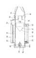
実施形態に係る吸入器の外観斜視図を図1に、その吸入器の構造の一例を示す分解斜視図を図2に、同吸入器の縦断面図を図3に示す。
【0015】
この吸入器は、内部が薬剤の流路となる筒状のケース10を備える。ケース10は、電源として2個の電池20を収納する電池収納部12を有し、電池収納部12の両端には電池端子21が取付けられ、電池収納部12には電池カバー22が着脱可能に取付けられる。
【0016】
また、ケース10は、電池収納部12の反対側に電子回路収納部14を有し、電子回路収納部14には制御手段としてのCPU31やスイッチ32等が実装された基板30が収納され、電子回路収納部14にはカバー34が装着されている。スイッチ32は、カバー34に形成された挿通孔34aに挿通されてケース10の表側に現出する。
【0017】
ケース10の一端側の開口にはマウスピース40が着脱自在に嵌着され、他端側の開口にはボトムカバー42が嵌着されている。ボトムカバー42は空気孔42aを有する。ボトムカバー42の空気孔42aには、部分的に開口するニードル44が挿入され、ニードル44は薬剤を収容したカプセル45を貫通し、ニードル44の開口がカプセル45内に位置する。カプセル45は、ボトムカバー42の内側に突設された支持枠42bに嵌入されることで支持される。
【0018】
ケース10内部には、カプセル45側に斜面を向けて円錐形状の回転子50が回転可能に配置されている。回転子50は、円錐形状の斜面部51と円板状の基部52とからなり、基部52の外周面とケース10の内周面との間には僅かな間隙が設けられている。回転子50の基部52の中心には、回転子50を回転駆動するモータ(駆動手段)55の回転軸が固定され、モータ55はケース10の内部に設けられたモータ取付部16の中心に取付けられている。勿論、モータ取付部16はその中心以外に空気及び薬剤が流れる空隙を有する。モータ55の回転軸、回転子50の中心軸、ニードル44は、ケース10の中心で一直線上に並んでいる。
【0019】
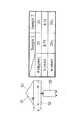
回転子50のサイズは、吸入器の大きさにもよるが、二例を示すと図4のとおりである。図4では、回転子50における斜面部51の斜面と基部52との成す角度をθ、基部52の厚さをh、基部52の外径(幅)をwとすると、サンプル1ではθを20度に、サンプル2ではθを30度に設定してある。サンプル1,2のいずれでもh,wは同じ値に設定される。
【0020】
このように構成された吸入器では、スイッチ32をONにすると、モータ55が作動し、回転子50が回転する。ここで、患者がマウスピース40から吸引すると、ケース10内部が負圧になるので、空気がボトムカバー42の空気孔42aからニードル44内を通り、ケース10内部に流入する。空気がニードル44内を通過するとき、カプセル45内の薬剤がニードル44の開口から吸い込まれ、ケース10内部に分散され、回転子50の方向に移動する。
【0021】
一方、回転子50の回転により、その斜面部51の近傍には層流が発生し、層流内に分布する薬剤には、薬剤内に生じる速度差によって発生する剪断応力が作用する。一般的に剪断応力は、その場所の速度勾配に比例する。例えば、図5のように物体表面に垂直な方向をy軸とすると、各位置での剪断応力τは速度勾配に比例し、次式で示される。
【0022】
τ=η(du/dy)、η:粘度
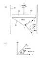
この剪断応力によって乳糖と薬剤が分離される。つまり、図6の(a)において、回転子50に対し、斜面部51に沿う方向をx軸、このx軸に垂直な方向をy軸、z軸とすると、図6の(b)のようにx軸方向に吸引力が、y軸方向に剪断応力τが作用する。
【0023】
通常は当該装置はマウスピース40側を上向きにして使用するので、分離された乳糖は重力により装置の下部に落下し、微小粒子の薬剤のみマウスピース40側に吸引される。従って、薬剤を目的とする治療患部(例えば肺内深部)に確実に到達させることができ、吸入による治療効果が高まる。更に、薬剤が回転中の斜面部51の表面を浮遊している間に、例えば針状結晶上の薬剤や偏平形状の薬剤は、一定の配向角度を持って浮遊する効果を持つようになる。これにより、薬剤の空気力学的粒子径を均一化することができ、体内への沈着効率を向上させることができる。
【0024】
別実施形態に係る吸入器の縦断面図を図7に示す。この吸入器は、上記実施形態の吸入器と比べて、薬剤を回転子50側に分散させて送るファン60を有する点だけが異なるので、それ以外の同じ要素には同一符号を付してある。ファン60は、ケース10内部におけるカプセル45と回転子50との間において、回転子50の中心に取付けられたシャフト61に取付けられ、回転子50と同軸上で一体に回転する。ファン60が回転子50と共に回転することで、カプセル45から分散した薬剤を回転子50の斜面部51に向かって強制的に送ることができるので、より一層、乳糖からの薬剤の剥離効果が高くなる。
【0025】
また、回転子50、ファン60及びモータ55を同一の回転軸上に位置させてあるので、3つの要素が一直線上に並び、省スペース化は勿論のこと、薬剤のカプセル45からの分散、薬剤の乳糖からの分離、分離後の薬剤の送出といった空気流れの中での一連の作用を効率良く行うことができる。
【0026】
更に、別実施形態に係る吸入器の構造の一例を示す分解斜視図を図8に、その吸入器の縦断面図を図9に示す。この吸入器は、図7の吸入器の構成に加えて、回転子50の回転速度を検出する検出手段としてフォトセンサ65が設けられている。ここでは、反射型のフォトセンサ65に対応して、ファン60の先端に被検出部60aが設けられている。フォトセンサ65は、基板30の裏側に実装され、ケース10内部に現出している。ファン60の被検出部60aは、例えば黒線が施されたもので、フォトセンサ65に対向しており、ファン60、すなわち回転子50の回転速度がフォトセンサ65で検出される。
【0027】
この場合の概略ブロック図を図10に示す。吸気センサ70は、フォトセンサ65とファン60の被検出部60aで構成され、フォトセンサ65で検出された回転子50の回転速度は制御部(CPU)31に取り込まれる。CPU31は、回転子50の回転速度に応じてモータ55の回転速度をいわばフィードバック制御する。
【0028】
CPU31により回転子50の回転を様々に制御できる。例えば、回転子50の回転速度(回転数)を変化させて、薬剤の粒子径分布を任意に変えることができる。或いは、患者の吸入速度を計測し、吸入速度に応じて回転子50の回転を調整できる。この場合、患者の吸入速度に依存しない粒子径の薬剤を発生させることができる。例えば、図11は回転子50の回転数に対する薬剤の粒子径とその分布度合をグラフで示す。このグラフから分かるように、回転子50が回転しないとき(回転子50を設けないとき)は、粒子径は約7μmを中心として分布するが、回転子50の回転数が7000rpmのときは約5μm、10000rpmでは約2μmをそれぞれ中心とする分布状態に変化する。従って、患者の吸入速度に関係なく、回転子50の回転速度を制御することで、任意の粒子径分布状態を発生させることができる。
【0029】
この他、患者の吸気に同期して回転子50の回転を開始するように制御してもよい。この場合、スイッチ32は不要である。
【0030】
【発明の効果】
以上説明したように、この発明によれば、薬剤の供給源から分散した薬剤に回転子の回転により剪断応力が加わるので、薬剤が乳糖から容易に分離する。この結果、薬剤を目的とする治療患部(例えば肺内深部)に確実に到達させることができ、吸入による治療効果が高まる。
【0031】
また、乳糖から剥離した薬剤は、回転する回転子の斜面上を浮遊している間に、例えば針状結晶上の薬剤や偏平形状の薬剤には、一定の配向角を持って浮遊する効果が付与され、薬剤の空気力学的粒子径を均一化でき、薬剤の体内への沈着効率を向上させることができる。
【図面の簡単な説明】
【図1】一実施形態に係る吸入器の外観斜視図である。
【図2】図1の吸入器の構造を示す分解斜視図である。
【図3】図1の吸入器の縦断面図である。
【図4】同吸入器における回転子の各部の寸法例を示す図である。
【図5】同吸入器において薬剤に作用する剪断応力を説明する図である。
【図6】同吸入器において回転子の回転により薬剤に作用する剪断応力を説明する図である。
【図7】別実施形態に係る吸入器の縦断面図である。
【図8】更に別実施形態に係る吸入器の構造を示す分解斜視図である。
【図9】図8の吸入器の縦断面図である。
【図10】図8の吸入器の概略ブロック図である。
【図11】同吸入器における回転子の回転数に対する薬剤の粒子径とその分布度合を示すグラフである。
【符号の説明】
10 ケース
20 電池
31 CPU(制御手段)
45 カプセル(薬剤供給源)
50 回転子
51 斜面部
52 基部
55 モータ(駆動手段)
60 ファン
60a 被検出部
65 フォトセンサ(検出手段)[0001]
BACKGROUND OF THE INVENTION
The present invention relates to an aerosol particle sorting device used in an inhaler used by a respiratory disease person to inhale a drug, and an inhaler including the device.
[0002]
[Prior art]
In order to control or improve the pathology of respiratory diseases such as asthma patients, dry powder inhalers that inhale powdered drugs are on the market. A dry powder drug is one in which a drug (medicinal component) of several μm adheres to lactose of several tens of μm to around 100 μm as an excipient. The dry powder inhaler is inhalable by a patient, generates turbulent flow by the patient's inhaled airflow, and separates the drug from lactose by the turbulent flow for inhalation.
[0003]
[Problems to be solved by the invention]
However, such conventional inhalers have the following problems (1) to (3).
(1) The degree of turbulent flow generated by the patient's inhalation greatly depends on the patient's inspiratory flow rate. For example, if a sufficient inspiratory flow rate cannot be obtained, such as a severely ill patient or a child, Insufficient separation of medicinal ingredients from lactose will not be sufficient. Lactose that has been left attached to the drug collides with the pharynx because of its relatively large inertia, and deposits in the upper respiratory tract due to its large diameter, so it cannot reach the deep lung area, which is the target treatment area. .
(2) The dosage form of the drug is not spherical, but is a needle shape or a vertically long flat shape. Drug particles generated from commercially available dry powder inhalers have various orientation angles, so the aerodynamic diameter is not constant and has a wide distribution, and the site of drug deposition also shows a wide distribution. For this reason, there are variations in the therapeutic effect among patients, and even in the same patient, the therapeutic effect varies.
(3) In the conventional inhaler, the particle size distribution having a wide distribution range was sprayed at once, but the particle size distribution to be sprayed could not be arbitrarily selected.
[0004]
The present invention has been made paying attention to such problems, and is capable of efficiently separating a drug from lactose regardless of the amount of inhalation of a patient, making a drug orientation angle constant, and particles of a drug. It is an object of the present invention to provide an aerosol particle sorting device and an inhaler that can realize a change in diameter distribution.
[0005]
[Means for Solving the Problems]
In order to solve the above-mentioned problems, an aerosol particle sorting device according to the present invention is a device used in an inhaler used for inhaling a medicine, and a slope is directed to the medicine supply source side in the medicine flow path. A rotor having a shape selected from a conical shape, a hemispherical shape, a shape in which a base is provided on the bottom surface of the cone, and a shape in which a base is provided on the bottom surface of the hemisphere, and driving means for rotationally driving the rotor. It is characterized by providing.
[0006]
In this apparatus, when the rotor rotates, a laminar flow is generated in the vicinity of the inclined surface of the rotor, and a shear stress generated by a speed difference generated in the drug acts on the drug distributed in the laminar flow. Accordingly, when the drug dispersed from the drug supply source passes through the rotor, it is easily separated from lactose by shear stress. As a result, it is possible to reliably reach the therapeutically affected part (for example, deep inside the lung) for the purpose of the medicine, and the therapeutic effect by inhalation is enhanced.
[0007]
Furthermore, while the drug released from lactose floats on the slope of the rotating rotor, for example, a drug on a needle crystal or a flat-shaped drug has the effect of floating with a certain orientation angle. The aerodynamic particle diameter of the drug can be made uniform, and the deposition efficiency of the drug in the body can be improved.
[0008]
In addition to the basic configuration described above, a fan that distributes the medicine to the rotor side and sends it between the medicine supply source and the rotor is arranged so that the medicine dispersed from the medicine supply source is placed on the rotor slope. Since the medicine can be forcibly sent, the effect of peeling the drug from lactose is further enhanced.
[0009]
The detection result of the detection means includes a detection means for detecting the rotation speed of the rotor and a control means for controlling the rotation speed of the rotor according to the rotation speed of the rotor detected by the detection means. Various controls are possible depending on the situation. For example, the particle size distribution of the drug can be arbitrarily changed by changing the rotation speed (number of rotations) of the rotor. Alternatively, it is possible to control the patient's inhalation speed and rotate the rotor according to the inhalation speed. In this case, it is possible to generate a drug having a particle size independent of the patient's inhalation speed. In addition, the rotation of the rotor may be started in synchronization with the patient's inspiration.
[0010]
On the other hand, if the rotor and the fan are mounted on the same rotating shaft, only one driving means is required, and not only the number of parts and cost can be reduced, but also space saving can be achieved. In this connection, by further positioning the rotor, fan, and driving means on the same rotation axis, the three elements are aligned in a straight line, saving space as well as distributing from the drug supply source. A series of actions in an air flow such as separation of the drug from lactose and delivery of the drug after separation can be efficiently performed.
[0011]
On the other hand, the inhaler of the present invention rotates in a cylindrical case whose inside is a drug flow path, a drug supply source disposed on one end side of the case, and an inclined surface toward the drug supply source side in the case Rotor having a shape selected from a conical shape, a hemispherical shape, a shape in which a base is provided on the bottom of the cone, and a shape in which a base is provided on the bottom of the hemisphere, and driving means for rotationally driving the rotor It is characterized by providing. This inhaler is provided with the aerosol particle sorting device, and the same effect can be obtained.
[0012]
In the present invention, the cone does not only indicate a shape having a sharp apex, but also includes a shape obtained by slightly cutting the tip (vertex) of the cone.
[0013]
DETAILED DESCRIPTION OF THE INVENTION
Hereinafter, the present invention will be described in more detail with reference to embodiments.
[0014]
FIG. 1 is an external perspective view of an inhaler according to the embodiment, FIG. 2 is an exploded perspective view showing an example of the structure of the inhaler, and FIG. 3 is a longitudinal sectional view of the inhaler.
[0015]
This inhaler includes a
[0016]
The
[0017]
A
[0018]
A
[0019]
Although the size of the
[0020]
In the inhaler configured as described above, when the
[0021]
On the other hand, due to the rotation of the
[0022]
τ = η (du / dy), η: Viscosity Lactose and drug are separated by this shear stress. That is, in FIG. 6A, when the direction along the
[0023]
Usually, since the apparatus is used with the
[0024]
FIG. 7 shows a longitudinal sectional view of an inhaler according to another embodiment. This inhaler is different from the inhaler of the above-described embodiment only in that it has a
[0025]
Further, since the
[0026]
FIG. 8 is an exploded perspective view showing an example of the structure of an inhaler according to another embodiment, and FIG. 9 is a longitudinal sectional view of the inhaler. This inhaler is provided with a photosensor 65 as detection means for detecting the rotational speed of the
[0027]
A schematic block diagram in this case is shown in FIG. The
[0028]
The
[0029]
In addition, the
[0030]
【The invention's effect】
As described above, according to the present invention, since the shearing stress is applied to the drug dispersed from the drug supply source by the rotation of the rotor, the drug is easily separated from the lactose. As a result, it is possible to reliably reach the therapeutically affected part (for example, deep inside the lung) for the purpose of the medicine, and the therapeutic effect by inhalation is enhanced.
[0031]
In addition, while the drug released from lactose is floating on the slope of the rotating rotor, for example, the drug on the needle-like crystal or the flat drug has the effect of floating with a certain orientation angle. The aerodynamic particle diameter of the drug can be made uniform, and the deposition efficiency of the drug in the body can be improved.
[Brief description of the drawings]
FIG. 1 is an external perspective view of an inhaler according to an embodiment.
2 is an exploded perspective view showing a structure of the inhaler of FIG. 1. FIG.
3 is a longitudinal sectional view of the inhaler of FIG. 1. FIG.
FIG. 4 is a view showing an example of dimensions of each part of a rotor in the inhaler.
FIG. 5 is a diagram for explaining shear stress acting on a medicine in the inhaler.
FIG. 6 is a diagram for explaining shear stress acting on a medicine by rotation of a rotor in the inhaler.
FIG. 7 is a longitudinal sectional view of an inhaler according to another embodiment.
FIG. 8 is an exploded perspective view showing a structure of an inhaler according to still another embodiment.
9 is a longitudinal sectional view of the inhaler of FIG.
10 is a schematic block diagram of the inhaler of FIG.
FIG. 11 is a graph showing the drug particle size and the degree of distribution with respect to the number of rotations of the rotor in the inhaler.
[Explanation of symbols]
10
45 capsules (drug source)
50
60
Claims (6)
Translated fromJapanese薬剤の流路において薬剤の供給源側に斜面を向けて配置される円錐形状、半球形状、円錐の底面に基部を設けた形状、半球の底面に基部を設けた形状の中から選ばれる形状の回転子と、この回転子を回転駆動する駆動手段とを備えることを特徴とするエアロゾル粒子分別装置。A device used in an inhaler used for inhaling a medicament,
A shape selected from a conical shape, a hemispherical shape, a shape having a base portion on the bottom surface of the cone, and a shape having a base portion on the bottom surface of the hemisphere in the drug flow path with the inclined surface facing the drug supply source side An aerosol particle sorting apparatus comprising: a rotor; and a driving unit that rotationally drives the rotor.
Priority Applications (4)
| Application Number | Priority Date | Filing Date | Title |
|---|---|---|---|
| JP2001278974AJP3619176B2 (en) | 2001-09-14 | 2001-09-14 | Aerosol particle sorting device and inhaler |
| US10/241,977US20030056789A1 (en) | 2001-09-14 | 2002-09-10 | Module of drug particle separator and inhaler provided with same |
| EP02020687AEP1293225B1 (en) | 2001-09-14 | 2002-09-13 | Dry powder inhaler |
| DE60221611TDE60221611T2 (en) | 2001-09-14 | 2002-09-13 | dry powder inhaler |
Applications Claiming Priority (1)
| Application Number | Priority Date | Filing Date | Title |
|---|---|---|---|
| JP2001278974AJP3619176B2 (en) | 2001-09-14 | 2001-09-14 | Aerosol particle sorting device and inhaler |
Publications (2)
| Publication Number | Publication Date |
|---|---|
| JP2003079731A JP2003079731A (en) | 2003-03-18 |
| JP3619176B2true JP3619176B2 (en) | 2005-02-09 |
Family
ID=19103249
Family Applications (1)
| Application Number | Title | Priority Date | Filing Date |
|---|---|---|---|
| JP2001278974AExpired - Fee RelatedJP3619176B2 (en) | 2001-09-14 | 2001-09-14 | Aerosol particle sorting device and inhaler |
Country Status (4)
| Country | Link |
|---|---|
| US (1) | US20030056789A1 (en) |
| EP (1) | EP1293225B1 (en) |
| JP (1) | JP3619176B2 (en) |
| DE (1) | DE60221611T2 (en) |
Families Citing this family (20)
| Publication number | Priority date | Publication date | Assignee | Title |
|---|---|---|---|---|
| GB9924780D0 (en) | 1999-10-21 | 1999-12-22 | Glaxo Group Ltd | Medicament dispenser |
| GB9924808D0 (en)* | 1999-10-21 | 1999-12-22 | Glaxo Group Ltd | Medicament dispenser |
| FR2856930B1 (en)* | 2003-07-04 | 2007-09-07 | Saime Sarl | MODULAR TURBINE BREATHING AIDING DEVICE. |
| CA2559403C (en) | 2004-01-22 | 2013-01-15 | Amir Belson | Respiratory system for inducing therapeutic hypothermia |
| US7168101B2 (en)* | 2005-02-14 | 2007-01-30 | Tesfa Guma | Security underwear device for sexual organs |
| WO2007089477A2 (en) | 2006-01-31 | 2007-08-09 | Oriel Therapeutics, Inc. | Dry powder inhalers having spiral travel paths, unit dose microcartridges with dry powder, related devices and methods |
| JP5713406B2 (en)* | 2008-12-02 | 2015-05-07 | クール セラピューティクス, インコーポレイテッド | System for delivery of respiratory gases with fine ice particles |
| IL298116A (en) | 2010-12-22 | 2023-01-01 | Syqe Medical Ltd | Method and system for drug delivery |
| JP2013132473A (en)* | 2011-12-27 | 2013-07-08 | Omron Healthcare Co Ltd | Nebulizer and nebulizer kit |
| US10238831B2 (en) | 2013-09-08 | 2019-03-26 | Qool Therapeutics, Inc. | Temperature measurement and feedback for therapeutic hypothermia |
| CA3215815A1 (en)* | 2014-06-30 | 2016-01-07 | Syqe Medical Ltd. | Method and device for vaporization and inhalation of isolated substances |
| RU2721064C2 (en) | 2014-06-30 | 2020-05-15 | Сике Медикал Лтд. | Flow-controlled inhaler |
| AU2015283589B2 (en) | 2014-06-30 | 2019-09-12 | Syqe Medical Ltd. | Method and device for vaporization and inhalation of isolated substances |
| US11298477B2 (en) | 2014-06-30 | 2022-04-12 | Syqe Medical Ltd. | Methods, devices and systems for pulmonary delivery of active agents |
| CN106659858B (en) | 2014-06-30 | 2020-11-24 | Syqe医药有限公司 | Medication dose box for inhaler device |
| WO2016138045A1 (en) | 2015-02-23 | 2016-09-01 | Qool Therapeutics, Inc. | Systems and methods for endotracheal delivery of frozen particles |
| CA3009599A1 (en) | 2016-01-06 | 2017-07-13 | Syqe Medical Ltd. | Low dose therapeutic treatment |
| WO2018069675A1 (en) | 2016-10-11 | 2018-04-19 | British American Tobacco (Investments) Limited | Aerosol provision system and method |
| US20220184326A1 (en)* | 2019-03-11 | 2022-06-16 | Health Research, Inc. | Medicinal nebulizer and method of dispensing medicament |
| CN119405953B (en)* | 2024-12-10 | 2025-09-30 | 中国人民解放军陆军军医大学第一附属医院 | Inhaled drug delivery devices |
Family Cites Families (12)
| Publication number | Priority date | Publication date | Assignee | Title |
|---|---|---|---|---|
| US3831606A (en)* | 1971-02-19 | 1974-08-27 | Alza Corp | Auto inhaler |
| GB1459426A (en)* | 1973-02-26 | 1976-12-22 | Allen & Hanburys Ltd | Inhalation devices |
| US3971377A (en)* | 1974-06-10 | 1976-07-27 | Alza Corporation | Medicament dispensing process for inhalation therapy |
| IT1116047B (en)* | 1979-04-27 | 1986-02-10 | Sigma Tau Ind Farmaceuti | DEVICE FOR THE QUICK INHALATION OF POWDER DRUGS BY PERSONS SUFFERING FROM ASTHMA |
| EP0069715B1 (en)* | 1981-07-08 | 1986-11-05 | Aktiebolaget Draco | Powder inhalator |
| DE3419148C1 (en)* | 1984-05-23 | 1985-08-01 | Hans Ulrich 7912 Weißenhorn Klimt | Inhalation device |
| US4739754A (en)* | 1986-05-06 | 1988-04-26 | Shaner William T | Suction resistant inhalator |
| DK0665759T3 (en)* | 1992-10-19 | 1999-08-23 | Dura Pharma Inc | The dry powder inhaler |
| WO1995005208A1 (en)* | 1993-08-18 | 1995-02-23 | Fisons Plc | Inhalator with breath flow regulation |
| US6102036A (en)* | 1994-04-12 | 2000-08-15 | Smoke-Stop | Breath activated inhaler |
| SE9700937D0 (en)* | 1997-03-14 | 1997-03-14 | Astra Ab | Powder inhales I |
| US6237591B1 (en)* | 1998-11-02 | 2001-05-29 | Dura Pharmaceuticals, Inc. | Turbine dry powder inhaler |
- 2001
- 2001-09-14JPJP2001278974Apatent/JP3619176B2/ennot_activeExpired - Fee Related
- 2002
- 2002-09-10USUS10/241,977patent/US20030056789A1/ennot_activeAbandoned
- 2002-09-13DEDE60221611Tpatent/DE60221611T2/ennot_activeExpired - Lifetime
- 2002-09-13EPEP02020687Apatent/EP1293225B1/ennot_activeExpired - Lifetime
Also Published As
| Publication number | Publication date |
|---|---|
| DE60221611D1 (en) | 2007-09-20 |
| JP2003079731A (en) | 2003-03-18 |
| EP1293225A3 (en) | 2003-08-20 |
| US20030056789A1 (en) | 2003-03-27 |
| EP1293225B1 (en) | 2007-08-08 |
| EP1293225A2 (en) | 2003-03-19 |
| DE60221611T2 (en) | 2008-05-21 |
Similar Documents
| Publication | Publication Date | Title |
|---|---|---|
| JP3619176B2 (en) | Aerosol particle sorting device and inhaler | |
| CN110799231B (en) | Dry powder conveying device and using method thereof | |
| US11247003B2 (en) | Systems and methods of aerosol delivery with airflow regulation | |
| ES2253898T3 (en) | DEVICE FOR THE ADMINISTRATION OF PHARMACOS AND MEDICINES. | |
| ES2703215T3 (en) | Nozzle inlet air flow control for aerosol generators | |
| CN102438685B (en) | Rotating box system for dry powder inhalers | |
| CN1859938B (en) | Unit dose cartridge and dry powder inhaler | |
| JP2927836B2 (en) | Drug supply device | |
| ES2256293T3 (en) | INHALERS. | |
| EP3117858A1 (en) | Nebulizer for infants and respiratory compromised patients | |
| NZ284315A (en) | Dry powder inhaler (self actuating); comprises a non motorised free spinning impeller rotatably mounted within a housing, a plurality of inlets passing through the housing to enter a mixing chamber and an outlet to a mouthpiece | |
| US20090056708A1 (en) | Device, system and method for targeting aerosolized particles to a specific area of the lungs | |
| US20230293832A1 (en) | Dry powder nebulizer | |
| Islam et al. | Dry powder inhaler design and particle technology in enhancing Pulmonary drug deposition: Challenges and future strategies | |
| CN204910375U (en) | A rotary vertical capsule dry powder inhalation device | |
| JP2008500851A (en) | Unit dose dry powder inhaler | |
| US6237591B1 (en) | Turbine dry powder inhaler | |
| US20050039744A1 (en) | Delivery of dispersed powders | |
| CN216877481U (en) | Powdered medicament inhaler | |
| Terzano et al. | State of the art and new perspectives' on dry powder inhalers | |
| HK40021790B (en) | Dry powder delivery device and methods of use | |
| HK40021790A (en) | Dry powder delivery device and methods of use | |
| D’Lima | Characterization of a Novel Dry Powder Inhaler |
Legal Events
| Date | Code | Title | Description |
|---|---|---|---|
| A977 | Report on retrieval | Free format text:JAPANESE INTERMEDIATE CODE: A971007 Effective date:20040402 | |
| A131 | Notification of reasons for refusal | Free format text:JAPANESE INTERMEDIATE CODE: A131 Effective date:20040518 | |
| TRDD | Decision of grant or rejection written | ||
| A01 | Written decision to grant a patent or to grant a registration (utility model) | Free format text:JAPANESE INTERMEDIATE CODE: A01 Effective date:20041102 | |
| A61 | First payment of annual fees (during grant procedure) | Free format text:JAPANESE INTERMEDIATE CODE: A61 Effective date:20041111 | |
| R150 | Certificate of patent or registration of utility model | Free format text:JAPANESE INTERMEDIATE CODE: R150 | |
| FPAY | Renewal fee payment (event date is renewal date of database) | Free format text:PAYMENT UNTIL: 20071119 Year of fee payment:3 | |
| FPAY | Renewal fee payment (event date is renewal date of database) | Free format text:PAYMENT UNTIL: 20081119 Year of fee payment:4 | |
| FPAY | Renewal fee payment (event date is renewal date of database) | Free format text:PAYMENT UNTIL: 20081119 Year of fee payment:4 | |
| FPAY | Renewal fee payment (event date is renewal date of database) | Free format text:PAYMENT UNTIL: 20091119 Year of fee payment:5 | |
| FPAY | Renewal fee payment (event date is renewal date of database) | Free format text:PAYMENT UNTIL: 20101119 Year of fee payment:6 | |
| FPAY | Renewal fee payment (event date is renewal date of database) | Free format text:PAYMENT UNTIL: 20101119 Year of fee payment:6 | |
| FPAY | Renewal fee payment (event date is renewal date of database) | Free format text:PAYMENT UNTIL: 20111119 Year of fee payment:7 | |
| FPAY | Renewal fee payment (event date is renewal date of database) | Free format text:PAYMENT UNTIL: 20121119 Year of fee payment:8 | |
| FPAY | Renewal fee payment (event date is renewal date of database) | Free format text:PAYMENT UNTIL: 20121119 Year of fee payment:8 | |
| FPAY | Renewal fee payment (event date is renewal date of database) | Free format text:PAYMENT UNTIL: 20131119 Year of fee payment:9 | |
| R250 | Receipt of annual fees | Free format text:JAPANESE INTERMEDIATE CODE: R250 | |
| LAPS | Cancellation because of no payment of annual fees |