JP3618776B2 - Image processing apparatus and method - Google Patents
Image processing apparatus and methodDownload PDFInfo
- Publication number
- JP3618776B2 JP3618776B2JP05411094AJP5411094AJP3618776B2JP 3618776 B2JP3618776 B2JP 3618776B2JP 05411094 AJP05411094 AJP 05411094AJP 5411094 AJP5411094 AJP 5411094AJP 3618776 B2JP3618776 B2JP 3618776B2
- Authority
- JP
- Japan
- Prior art keywords
- edge
- image
- color
- maximum value
- color component
- Prior art date
- Legal status (The legal status is an assumption and is not a legal conclusion. Google has not performed a legal analysis and makes no representation as to the accuracy of the status listed.)
- Expired - Fee Related
Links
Images


Landscapes
- Facsimile Image Signal Circuits (AREA)
- Color Image Communication Systems (AREA)
- Image Analysis (AREA)
- Image Processing (AREA)
Description
Translated fromJapanese【0001】
【産業上の利用分野】
本発明は画像処理装置及び方法に関し、例えば写真画像、網点画像、文字画像を読み込んで出力する画像処理装置及び方法に関するものである。
【0002】
【従来の技術】
網点画像印刷方法とは、階調のある画像に対して画像を細かいドットの集合体に分解し、そのドットの大きさで疑似的に階調を表現する画像印刷方法である。
【0003】
しかし、網点画像印刷方法を用いて印刷出力された原稿画像を画素単位に読み込むと、読み込まれた画像データにはモアレと呼ばれるテクスチャが出現してしまう場合があった。そのため、従来の画像処理装置及び方法においては、読み込んだ画像からモアレを除去するために、読み込んだ画像データに対してフィルタリング等の処理を行う必要があった。
【0004】
しかしながら、読み込む原稿画像が文字や写真及び網点画像の混在した画像である場合には、一様にモアレ抑制のフィルタリング処理等を行うと、文字や写真画像の品位が損なわれてしまう場合が発生する。従って、文字や写真及び網点画像の混在画像を処理する場合には、モアレ抑制処理は網点画像の部分のみに施されるべきである。
【0005】
従って従来の画像処理装置及び方法においては、入力画像中から網点画像領域を判別する必要があり、その判別法としては網点のドットの孤立性を検出し、孤立したドットの集合体を網点画像領域として判別する方式や、ブロック毎の相関を取る方式など、様々な方法が提案されてきた。
【0006】
【発明が解決しようとする課題】
しかしながら、上述したような従来の網点画像領域判別方法はいずれも単色の画像データから網点画像を判別することを仮定した方法であった。一方、カラーの網点画像を含む原稿画像に対しては、各色成分毎の情報を用いて網点画像判別処理を行った手法は提案されておらず、従ってカラー画像において効率良く網点画像を判別することができなかった。
【0007】
【課題を解決するための手段】
本発明は上述した課題を解決するためになされたものであり、上述した課題を解決するために以下の構成を備える。
【0008】
即ち、注目画素の注目色成分のエッジ方向を判定するために、注目色成分の水平方向、垂直方向、及び斜め方向のエッジの度合いを示すエッジ量を算出し、算出した中の最大エッジ量を持つ方向を注目色成分のエッジ方向として検出し、この検出を色成分毎に行う検出手段と、前記検出手段で検出された色成分毎の最大エッジ量の中の最大値を求める最大値検出手段と、前記最大値検出手段で検出された最大値が所定の閾値以下である場合には、当該注目画素は写真画像領域に属すると判定する第1の判定手段と、前記最大値検出手段で検出された最大値が前記所定の閾値を超える場合において、少なくとも2つの色成分同士のエッジ方向が一致するときは、当該注目画素は文字線画領域に属すると判定し、各色成分のエッジ方向が他のいずれの色成分のエッジ方向にも一致しないときは、当該注目画素はカラー網点画像領域に属すると判定する第2の判定手段とを有することを特徴とする。
【0011】
【作用】
以上の構成により、色分解された入力画像から色成分毎の画像の特徴を捉えることにより、カラー網点画像領域と、文字線画像領域と写真画像領域とを判別することが可能になり、分離された各画像領域についてそれぞれ最適の画像処理等を施すことにより、高品位な画像を形成することができる。
【0013】
【実施例】
以下、図面を参照して本発明に係る一実施例について詳細に説明する。
【0014】
<第1実施例>
図1は、本実施例の画像処理装置の構成を示すブロック図である。
【0015】
図1において、101はCCDカラーセンサ、102はアナログ増幅部、103はA/D変換部、104はシェーディング補正部、105はプリント信号発生部、106は画像領域分離部である。また、108は読み取り同期信号発生部、111はカラープリンタであり、114は画像処理装置全体を制御するCPUである。
【0016】
CCDカラーセンサ101によって読み込まれた画像信号は、アナログ増幅部102で増幅され、A/D変換部103でアナログからデジタルに変換され、シェーディング補正部104に入力され、画像信号の読み取り位置による明るさのバラツキの補正を行う。シェーディング補正は原稿の位置による明るさ、色味の歪を補正するものであり、この補正により入力原稿のおかれる位置に関わらず、本実施例における画像領域の分離を正確に行うことができる。尚、シェーディング補正部104におけるシェーディング補正は公知技術であるため、その詳細については説明を省略する。
【0017】
シェーディング補正部104から出力された補正後の画像信号は画像領域分離部106に入力され、本実施例の特徴である画像領域分離を行い、領域判別信号107をプリント信号発生部105に出力する。
【0018】
プリント信号生成部105ではシェーディング補正部104から出力されたカラー信号R(レッド),G(グリーン),B(ブルー)を、Y(イエロー),M(マゼンタ),C(シアン),Bk(ブラック)信号に変換し、各種の補正処理を行う。尚、この補正処理は、画像領域分離部106からの領域判別信号107によってどのような補正処理を行うかが決定され、CPU114によって制御される。
【0019】
そして、プリント信号発生部105から出力されたY(イエロー),M(マゼンタ),C(シアン),Bk(ブラック)信号は、カラープリンタ111によって、カラー画像として最終的に出力される。
【0020】
また、以上に説明した各構成は、読み取り同期信号発生部108から発生される各同期信号により同期が取られる。読み取り同期信号発生部108からは、主走査有効区間信号HS,画素読み取り基本クロックCLK,副走査有効区間信号VSが発生される。
【0021】
次に、上述した画像領域分離部106について詳細に説明を行う。尚、画像領域分離部106は、本実施例の特徴をなすものである。
【0022】
図2は、画像領域分離部106の詳細構成を示すブロック図である。
【0023】
図2において、まずシェーディング補正回路104からの出力であるR(レッド)信号201、G(グリーン)信号202、B(ブルー)信号203がエッジ検出部204に入力される。このエッジ検出部204では、各画素毎にエッジの量及びその方向を検出することによって、画素毎の画像領域判別を行う。
【0024】
エッジ検出部204により写真画像判定信号(PICT信号)205,カラー網点画像判定信号(AMI信号)206,文字線画像判定信号(CHA信号)207のオン/オフが制御されて、1次平滑部208に入力される。1次平滑部208でまず第1次の平滑化処理が行われ、次いで2次平滑部212において第2次の平滑処理が行われる。尚、1次平滑部208,2次平滑部212における各平滑化処理は、それぞれメモリ210,213に格納されている周囲画素の情報を参照して行われ、メモリ210,213への読み込み/書き込みはCPU114により制御されている。
【0025】
本実施例では、上述した画像領域分離部106において入力画像から網点の色毎のエッジの方向を検出し、検出されたエッジ方向が色毎に異なるとカラー網点画像領域であると判別する。
【0026】
多色刷りの網点印刷による画像は色成分毎にスクリーン角を有しており、エッジの方向はスクリーン角に依存する。そのため、網点画像を色分解した画像信号からエッジ成分を抽出すると、色毎にその方向が異なるという特徴がある。一方、文字原稿は、例えば多色刷りによるカラー原稿であっても各色は重ね合わされているため、色成分毎のエッジの方向は一致する。そこで、本実施例においては、上述した画像によるエッジ方向の特徴を利用することにより、カラー網点原稿と文字原稿、さらには写真等の中間調の原稿などが混在した入力原稿から、カラー網点画像領域、文字線画像領域、写真画像領域とを分離する。
【0027】
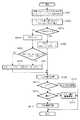
上述したような構成をなす画像領域分離部106における画像領域分離処理を、図3のフローチャートを参照して詳細に説明する。
【0028】
まずステップS301において、各画素を構成するR,G,Bの各色成分毎にフィルタ関数を用いて5×5画素のフィルタリング処理を行い、それぞれのエッジ及びその方向を検出する。
【0029】
本実施例における5×5画素のフィルタリング処理について、以下に説明する。
【0030】
例えば、座標(xi,yi)である注目画素に対して5×5画素のフィルタリング処理を行う場合、係数マトリクスを図4のように、例えば座標(xi,yi)の濃度値がf(xi,yj)である注目画素に対する係数はa33であるとすると、各座標毎に以下の式(1)に示すフィルタ関数Fによりフィルタリング処理が施される。
【0031】
【0032】
本実施例においては、図5の(a)から(h)に示す8種類の係数マトリクスを用いて、上述したフィルタ関数(1)によりフィルタリング処理を行う。尚、図5の各係数マトリクスにおいて、空白で示された係数部分は「0」を表わすものである。図5に示す8種類の係数マトリクスを用いてフィルタリング処理を行うことにより、即ち、8方向(L=1〜8)についてのエッジ成分の検出を行うことができ、本実施例において全ての方向についてのエッジ成分は、8方向のいずれかに近似される。
【0033】
上述したフィルタ関数(1)を用いて、まずR信号201に対して、図5に示す8方向のエッジ量DR1〜DR8を求める。
【0034】
次にこの8方向のエッジ量DR1〜DR8から、エッジ量の最大値DRMAXと、その方向LR (1〜8)を求める。同様にして、G信号202についてのエッジ量の最大値DGMAXとその方向LG 、B信号203についてのエッジ量の最大値DBMAXとその方向LB を求める。
【0035】
以上説明した様にステップS301においては、座標(xi,yi)における各RGB信号の最大エッジ量及びその方向を求める。
【0036】
次にステップS302において、ステップS301で求めた各RGB信号の最大エッジ量DRMAX,DGMAX,DBMAXの中から、最大であるDMAX 及びその方向LMAXを検出する。
【0037】
そして処理はステップS303に進み、銀塩写真等の連続階調画像領域(以下、写真画像領域と呼ぶ)の判別を行う。即ち、適当な閾値θを境にして、ステップS302で検出したDMAX との関係がDMAX ≦θである場合に、当該画素は写真画像領域であると判断し、ステップS305に進む。ステップS305では、写真画像判定信号(PICT)205をHレベルとし、カラー網点画像判定信号(AMI)206と、文字線画像判定信号(CHA)207とをLレベルとして、次段の1次平滑化部208に出力する。
【0038】
一方、ステップS303においてDMAX >θである場合はステップS304に進み、写真画像判定信号(PICT)205をLレベルとし、ステップS306に進む。ステップS306においてはLR =LG ,又はLG =LB ,又はLB =LR のうちのいずれかが成り立つか否かを判定する。ステップS306において上述した各関係のうちのいずれかが成り立つのであれば、エッジの方向が色によらずに同一である文字線で構成された画像領域(文字線画像領域)であると判定され、ステップS307に進む。ステップS307においては、カラー網点画像判定信号(AMI)206をLレベル、文字線画像判定信号(CHA)207とをHレベルとして、ステップS309に進む。
【0039】
一方、ステップS306において上述した各関係がすべて成り立たないのであれば、エッジ方向が色により異なることを特徴とするカラー網点画像領域であると判定され、ステップS308に進む。ステップS308においては、カラー網点画像判定信号(AMI)206をHレベル、文字線画像判定信号(CHA)207とをLレベルとして、ステップS309に進む。
【0040】
ステップS309では、図2に示す1次平滑化部208における第1の平滑化処理を行う。まずCPU114からの書き込み信号WEに従って、メモリ210に領域判別結果信号209を書き込む。尚、領域判別結果信号209は、PICT信号205がHレベルであれば「0」、AMI信号206がHレベルであれば「1」、CHA信号207がHレベルであれば「2」となる。
【0041】
次に、注目画素の周囲1画素分、即ち8画素分の領域判別結果をメモリ210から読み出し、3×3画素のウィンドウ処理による1次平滑化を行う。つまり、注目画素の周りを取り囲む8画素の領域判別結果が、いずれも注目画素の判別結果と異なる場合、注目画素の判別結果を周辺画素の判別結果のうちの多数である方に置き換える。この処理によって、局所的に出現した誤判定を除去することが可能となる。ステップS309において以上のようにして平滑化処理が施された後、処理はステップS310に進む。
【0042】
ステップS310においては、2次平滑化部212で注目画素が文字線画像領域であった場合に、平滑化処理を行う。ステップS312では、まず1次平滑化信号211をメモリ213に書き込む。次に、注目画素に対して周囲2画素分、即ち24画素分の領域判別結果をメモリ213から読み込み、5画素×5画素のウィンドウ処理による2次平滑化を行う。本実施例における2次平滑化部212における文字線画像領域の平滑化処理の例を、図6を参照して説明する。
【0043】
図6は、2次平滑化部212における文字線画像領域を判別する条件を示す図である。図6の(a)に示すように5×5画素のウインドウについて、各画素のCHA信号がCmnであるとした場合、図6の(b)に示す全28個の条件のうちの各CHA信号のいずれかがHレベルであれば、当該注目画素は文字線画像領域であると判別する。
【0044】
上述したようにしてステップS310において注目画素が文字線画像領域であると判別されると、処理はステップS311に進み、文字線画像領域として注目画素の領域判別結果を「2」に補正する。
【0045】
一方、ステップS310において図6に示す条件がいずれも成立しなかった場合、注目画素が文字線画像領域ではないと判別され、処理はステップS312に進み、今度は注目画素が網点画像であるか否かを判定する。ステップS312では、25画素中においてAMI信号がHレベルである画素を数える。25画素中のAMI信号がHレベルである画素数としては、適当な閾値δが予め設定されており、この閾値δよりもAMI信号がHレベルである画素数が多い場合に、注目画素はカラー網点画像領域であると判別する。
【0046】
上述したようにしてステップS312において注目画素がカラー網点画像領域であると判別されると、処理はステップS313に進み、カラー網点画像領域として注目画素の領域判別結果を「1」に補正する。
【0047】
一方、ステップS312においてAMI信号がHレベルである画素数が、閾値δよりも少なかった場合、注目画素は写真画像領域であると判別され、ステップS314で注目画素の領域判別結果が「0」に補正される。
【0048】
以上説明したようにして、画像領域分離部106においては注目画素の画像領域を判別する。そして領域判別結果はプリント信号発生部105に入力される。
【0049】
尚、以上の説明においては、エッジ方向毎の濃度変化を検出するためのフィルタ関数として、(1)式を例として説明を行ったが、この例に限ることなく、エッジ量及び方向を得ることができるものであれば何でもよい。また、その際に処理を行う色信号の順序も不同である。
【0050】
次に、プリント信号発生部105について説明を行う。
【0051】
図7は、プリント信号発生部105の詳細構成を示すブロック図である。
【0052】
図7において、700はLOG変換部であり、入力されるRGBの3色信号を、プリント出力用のYMC信号に変換する。LOG変換部700でLOG変換された信号はマスキングUCR演算部A701,マスキングUCR演算部B702,マスキングUCR演算部C703に入力される。マスキングUCR演算部A701では、公知のUCR処理が行われ、YMC信号からBk信号を生成する。また、マスキングUCR演算部B702では、入力YMC信号に対して3×3画素の公知のスムージング処理を行い、その後、公知のUCR処理を行って、Bk信号を生成する。また、マスキングUCR演算部C703では、入力YMC信号に対して3×3画素の公知のエッジ強調処理を行い、その後、公知のUCR処理を行って、Bk信号を生成する。
【0053】
以上説明したようにマスキングUCR演算部A701,マスキングUCR演算部B702,マスキングUCR演算部C703から出力されるそれぞれのプリント用YMCBk信号は、全てセレクタ704に入力される。セレクタ704には上述した図1に示す画像領域分離部106からの画像領域判別信号107が入力されており、この画像領域判別信号に従って、前記マスキングUCR演算部A701,マスキングUCR演算部B702,マスキングUCR演算部C703からの出力を選択して、カラープリンタ111に出力する。
【0054】
即ち、画像領域判別信号107が「0」であれば写真画像領域であるとしてマスキングUCR演算部A701からのYMCBk信号が、また、画像領域判別信号107が「1」であればカラー網点画像領域であるとしてマスキングUCR演算部B702からのスムージング処理を施されたYMCBk信号が、また、画像領域判別信号107が「2」であれば文字線画像領域であるとしてマスキングUCR演算部C703からのエッジ強調処理が施されたYMCBk信号が、セレクタ704において選択される。
【0055】
以上説明したように本実施例によれば、カラー原稿からカラー網点画像領域及び文字線画像領域、写真画像領域を判別し、それぞれに適した画像処理を施すことにより、より最適な画像処理を行うことが可能となる。
【0056】
<第2実施例>
以下、本発明に係る第2実施例について説明する。
【0057】
上述した第1実施例においては、シェーディング補正部104から出力されたRGBの画像信号に対して、画像領域分離部106で画像領域判別処理を行い、プリント信号発生部105においてLOG変換処理等を行っていた。第2実施例においては、上述した第1実施例と異なり、RGB信号にLOG変換処理を施した後に、画像領域判別処理を行う場合について説明を行う。
【0058】
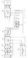
図8は、第2実施例の画像処理装置の構成を示すブロック図である。図8において、上述した第1実施例の図1に示す構成と同一の構成には同一番号を付し、説明を省略する。
【0059】
図8において、801はLOG変換部であり、上述した第1実施例の図7に示すLOG変換部700と同様である。また、802はプリント信号発生部であり、第1実施例の図1に示すプリント信号発生部105は図7に示すようにLOG変換部700を保持していたが、第2実施例のプリント信号発生部802はこれを保持しない。
【0060】
即ち、第2実施例においては、シェーディング補正部104から出力されたRGB信号をLOG変換部801でLOG変換することによりCMY信号に変換する。このCMY信号は画像領域分離部106に入力され、上述した第1実施例と同様の係数マトリクスを用いて各色のエッジを検出し、画像領域を判別する。そして、プリント信号発生部802において、画像領域分離部106から出力された画像領域判別信号107に従ってUCR処理をはじめとする適当な画像処理を行い、カラープリンタ111から画像を印刷出力する。
【0061】
以上説明したように第2実施例によっても、上述した第1実施例と同様の効果が得られる。
【0062】
<第3実施例>
以下、本発明に係る第3実施例について説明する。
【0063】
第3実施例においては、入力されたカラー画像を通常の単色の網点画像判別処理に加え、上述した第1実施例におけるカラー網点画像判別処理を更に行う。
【0064】
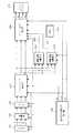
図9は、第3実施例の画像処理装置の構成を示すブロック図である。図9において、上述した第1実施例の図1に示す構成と同一の構成には同一番号を付し、説明を省略する。
【0065】
図9において、901は画像領域分離部A、902は画像領域分離部Bであり、903はプリント信号発生部である。
【0066】
画像領域分離部A901はRGBの画像信号を入力とし、各色についてそれぞれ公知の単色用の網点画像判別処理を行い、画像領域判別信号907が出力される。また、画像領域分離部B902は、上述した第1実施例の画像領域分離部106と同様であり、第1実施例と同様に画像判別信号107を出力する。プリント信号発生部903では、画像領域分離部A901,画像領域分離部B902から出力されたそれぞれの画像判別信号907,107により、最適な画像処理を選択する。
【0067】
例えば、画像判別信号907により網点画像であると判定された画素と、画像判別信号107により網点画像であると判定された画素との和を網点画像として判別することにより、通常の単色の網点画像判別処理では見落とされていた網点画像も検出することができ、例えば網点画像中の文字等を判別することも可能となる。従って、より高精度での画像判別が可能となる。
【0068】
尚、第3実施例は、カラーインクが比較的均等に分布しているような画像において、特に効果的である。
【0069】
以上説明したように第3実施例によれば、従来の方法による画像領域判別処理では検出されなかった網点画像領域についても判別可能となり、より高精度の画像処理を行うことができる。
【0070】
また、第3実施例においては、上述した第1実施例の図1に示す画像領域分離部106の前段に画像領域分離部A901を備える構成について説明を行ったが、もちろん第2実施例の図8に示す画像領域分離部106の前段に、同様に単色用の画像領域分離部を設けても、同様の効果を得ることができる。
【0071】
尚、上述した第1〜第3実施例においては、最終出力先としてカラープリンタを例に説明を行ったが、本発明はこの例に限定されるものではなく、例えば外部装置へインタフェースを介して出力する等、画像信号を出力する装置であれば何でもよい。
【0072】
尚、本発明は、複数の機器から構成されるシステムに適用しても、1つの機器から成る装置に適用しても良い。また、本発明はシステム或は装置にプログラムを供給することによって達成される場合にも適用できることは言うまでもない。
【0073】
【発明の効果】
以上説明したように本発明によれば、色分解された入力画像から色成分毎の画像のエッジ情報を検出することにより、カラー網点画像領域と、文字線画像領域と写真画像領域とを判別することが可能になる。
【0076】
【図面の簡単な説明】
【図1】本発明に係る一実施例の画像処理装置の構成を示すブロック図である。
【図2】本実施例における画像領域分離部の詳細構成を示すブロック図である。
【図3】本実施例における画像領域判別処理を示すフローチャートである。
【図4】本実施例におけるエッジ検出部でのフィルタリング処理で用いる係数マトリクスを示す図である。
【図5】本実施例におけるエッジ検出部でのフィルタリング処理で用いる実際のフィルタの係数マトリクスを示す図である。
【図6】本実施例における2次平滑化部での文字線画像判別条件を示す図である。
【図7】本実施例におけるプリント信号発生部の詳細構成を示すブロック図である。
【図8】本発明に係る第2実施例の画像処理装置の構成を示すブロック図である。
【図9】本発明に係る第3実施例の画像処理装置の構成を示すブロック図である。
【符号の説明】
101 CCDカラーセンサ
102 アナログ増幅部
103 A/D変換部
104 シェーディング補正部
105 プリント信号発生部
106 画像領域分離部
107 画像領域判定信号
108 読み取り同期信号発生部
111 カラープリンタ
114 CPU
204 エッジ検出部
208 1次平滑化部
210,213 メモリ
212 2次平滑化部
700 LOG変換部
701 マスキングUCR演算部A
702 マスキングUCR演算部B
703 マスキングUCR演算部C[0001]
[Industrial application fields]
The present invention relates to an image processing apparatus and method, for example, an image processing apparatus and method for reading and outputting a photographic image, a halftone dot image, and a character image.
[0002]
[Prior art]
The halftone image printing method is an image printing method in which an image is decomposed into an aggregate of fine dots with respect to an image having gradation, and a gradation is expressed in a pseudo manner by the size of the dot.
[0003]
However, when a document image printed and output using the halftone image printing method is read in units of pixels, a texture called moire may appear in the read image data. Therefore, in the conventional image processing apparatus and method, it is necessary to perform processing such as filtering on the read image data in order to remove moire from the read image.
[0004]
However, if the original image to be read is an image in which characters, photos, and halftone images are mixed, the quality of the characters and photo images may be impaired if the filtering process for moire suppression is performed uniformly. To do. Therefore, when processing a mixed image of characters, photographs, and halftone images, moire suppression processing should be performed only on the halftone image portion.
[0005]
Therefore, in the conventional image processing apparatus and method, it is necessary to discriminate the halftone dot image region from the input image. As the discrimination method, the isolation of the halftone dot is detected, and the group of isolated dots is halftone. Various methods such as a method of discriminating as a point image region and a method of obtaining a correlation for each block have been proposed.
[0006]
[Problems to be solved by the invention]
However, any of the conventional halftone dot image region discrimination methods as described above is a method that assumes that a halftone dot image is discriminated from single-color image data. On the other hand, for a manuscript image including a color halftone image, a method for performing halftone image discrimination processing using information for each color component has not been proposed. Therefore, a halftone image is efficiently displayed in a color image. Could not be determined.
[0007]
[Means for Solving the Problems]
The present invention has been made to solve the above-described problems, and has the following configuration in order to solve the above-described problems.
[0008]
That is, in order to determine the edge direction of the target color component of the target pixel, the edge amount indicating the degree of edge of the target color component in thehorizontal direction, the vertical direction, and the diagonal direction is calculated, and the calculated maximum edge amount is calculated. A detecting unit that detects the direction of the detected color component as an edge direction of the target color component and performs this detection for each color component; and a maximum value detecting unit that obtains a maximum value among the maximum edge amounts for each color component detected by the detecting unit And when the maximum value detected by the maximum value detecting means is equal to or less than a predetermined threshold, the first determining means for determining that the target pixel belongs to a photographic image area, and the maximum value detecting means In the case where the determined maximum value exceeds the predetermined threshold value, when the edge directions of at least two color components coincide with each other, it is determined that the target pixel belongs to the character / line drawing region, and the edge direction of each color component is different from the other Izu When the do not match the edge direction of the color components, the target pixel is characterized by a second judging means judges that belongs to a color halftone image area.
[0011]
[Action]
With the above configuration, it is possible to distinguish color halftone image areas, character line image areas, and photographic image areas by capturing the characteristics of the image for each color component from the color-separated input image. A high-quality image can be formed by performing optimum image processing or the like for each of the image areas.
[0013]
【Example】
Hereinafter, an embodiment according to the present invention will be described in detail with reference to the drawings.
[0014]
<First embodiment>
FIG. 1 is a block diagram showing the configuration of the image processing apparatus of this embodiment.
[0015]
In FIG. 1, 101 is a CCD color sensor, 102 is an analog amplification unit, 103 is an A / D conversion unit, 104 is a shading correction unit, 105 is a print signal generation unit, and 106 is an image region separation unit.
[0016]
The image signal read by the
[0017]
The corrected image signal output from the
[0018]
The print
[0019]
The Y (yellow), M (magenta), C (cyan), and Bk (black) signals output from the print
[0020]
In addition, each configuration described above is synchronized by each synchronization signal generated from the read synchronization
[0021]
Next, the image
[0022]
FIG. 2 is a block diagram illustrating a detailed configuration of the image
[0023]
In FIG. 2, first, an R (red) signal 201, a G (green) signal 202, and a B (blue) signal 203 that are outputs from the
[0024]
The
[0025]
In this embodiment, the image
[0026]
An image obtained by halftone dot printing has a screen angle for each color component, and the edge direction depends on the screen angle. Therefore, when an edge component is extracted from an image signal obtained by color-separating a halftone image, the direction is different for each color. On the other hand, even if the character document is a color document by multi-color printing, for example, the respective colors are superimposed, the edge directions for each color component match. Therefore, in the present embodiment, by utilizing the edge direction characteristics of the above-described image, a color halftone dot can be obtained from an input original in which a color halftone original and a character original, and a halftone original such as a photograph are mixed. The image area, the character line image area, and the photographic image area are separated.
[0027]
The image region separation processing in the image
[0028]
First, in step S301, 5 × 5 pixel filtering processing is performed using a filter function for each of R, G, and B color components constituting each pixel, and each edge and its direction are detected.
[0029]
The 5 × 5 pixel filtering process in this embodiment will be described below.
[0030]
For example, when a 5 × 5 pixel filtering process is performed on a pixel of interest at coordinates (xi, yi), the coefficient matrix has a density value of coordinates (xi, yi), for example, f (xi, yi) as shown in FIG. Assuming that the coefficient for the pixel of interest that is yj) is a33, a filtering process is performed for each coordinate by the filter function F shown in the following equation (1).
[0031]
[0032]
In the present embodiment, the filtering process is performed by the filter function (1) described above using the eight types of coefficient matrices shown in FIGS. In each coefficient matrix of FIG. 5, the coefficient part indicated by a blank represents “0”. By performing the filtering process using the eight kinds of coefficient matrices shown in FIG. 5, that is, edge components in eight directions (L = 1 to 8) can be detected. In this embodiment, all the directions are detected. The edge component of is approximated in one of eight directions.
[0033]
Using the filter function (1) described above, first, the edge amounts DR1 to DR8 in the eight directions shown in FIG.
[0034]
Next, from the edge amounts DR1 to DR8 in the eight directions, the maximum value DRMAX of the edge amount and its direction LR (1 to 8) are obtained. Similarly, the maximum edge amount value DGMAX and its direction LG for the G signal 202 and the maximum edge amount value DBMAX and its direction LB for the
[0035]
As described above, in step S301, the maximum edge amount and direction of each RGB signal at coordinates (xi, yi) are obtained.
[0036]
Next, in step S302, the maximum DMAX and its direction LMAX are detected from the maximum edge amounts DRMAX, DGMAX, and DBMAX of each RGB signal obtained in step S301.
[0037]
Then, the process proceeds to step S303 to determine a continuous tone image region (hereinafter referred to as a photographic image region) such as a silver halide photograph. That is, when the relationship with DMAX detected in step S302 is DMAX ≦ θ with an appropriate threshold θ as a boundary, it is determined that the pixel is a photographic image region, and the process proceeds to step S305. In step S305, the photographic image determination signal (PICT) 205 is set to the H level, the color halftone dot image determination signal (AMI) 206 and the character line image determination signal (CHA) 207 are set to the L level, and the primary smoothing of the next stage is performed. To the
[0038]
On the other hand, if DMAX> θ in step S303, the process proceeds to step S304, the photographic image determination signal (PICT) 205 is set to L level, and the process proceeds to step S306. In step S306, it is determined whether or not LR = LG, LG = LB, or LB = LR is satisfied. If any of the above-described relationships is established in step S306, it is determined that the edge region is an image region (character line image region) composed of the same character line regardless of the color, The process proceeds to step S307. In step S307, the color halftone dot image determination signal (AMI) 206 is set to L level and the character line image determination signal (CHA) 207 is set to H level, and the process proceeds to step S309.
[0039]
On the other hand, if all of the above relationships are not satisfied in step S306, it is determined that the color dot image region is characterized in that the edge direction differs depending on the color, and the process proceeds to step S308. In step S308, the color halftone image determination signal (AMI) 206 is set to H level and the character line image determination signal (CHA) 207 is set to L level, and the process proceeds to step S309.
[0040]
In step S309, a first smoothing process is performed in the
[0041]
Next, the region discrimination result for one pixel around the pixel of interest, that is, for eight pixels is read from the
[0042]
In step S310, if the target pixel is a character line image region in the
[0043]
FIG. 6 is a diagram showing conditions for determining the character line image area in the
[0044]
As described above, when it is determined in step S310 that the target pixel is the character line image region, the process proceeds to step S311 and the region determination result of the target pixel is corrected to “2” as the character line image region.
[0045]
On the other hand, if none of the conditions shown in FIG. 6 is satisfied in step S310, it is determined that the pixel of interest is not a character line image region, and the process proceeds to step S312 to determine whether the pixel of interest is a halftone image. Determine whether or not. In step S312, the number of pixels in which the AMI signal is at the H level among the 25 pixels is counted. As the number of pixels in which the AMI signal in the 25 pixels is at the H level, an appropriate threshold value δ is set in advance, and when the number of pixels in which the AMI signal is at the H level is larger than the threshold value δ, the target pixel is the color It is determined that it is a halftone image area.
[0046]
As described above, when it is determined in step S312 that the target pixel is a color halftone image area, the process proceeds to step S313, and the area determination result of the target pixel is corrected to “1” as the color halftone image area. .
[0047]
On the other hand, if the number of pixels whose AMI signal is at the H level is smaller than the threshold δ in step S312, it is determined that the target pixel is a photographic image region, and the region determination result of the target pixel is set to “0” in step S314. It is corrected.
[0048]
As described above, the image
[0049]
In the above description, the filter function for detecting the density change for each edge direction has been described by using the expression (1) as an example. However, the present invention is not limited to this example, and the edge amount and direction can be obtained. Anything can be used. Further, the order of the color signals to be processed at that time is not the same.
[0050]
Next, the
[0051]
FIG. 7 is a block diagram illustrating a detailed configuration of the print
[0052]
In FIG. 7,
[0053]
As described above, the printing YMCBk signals output from the masking UCR
[0054]
That is, if the image
[0055]
As described above, according to the present embodiment, a color halftone image area, a character line image area, and a photographic image area are discriminated from a color document, and image processing suitable for each is performed, so that more optimal image processing can be performed. Can be done.
[0056]
<Second embodiment>
The second embodiment according to the present invention will be described below.
[0057]
In the first embodiment described above, the image
[0058]
FIG. 8 is a block diagram illustrating the configuration of the image processing apparatus according to the second embodiment. In FIG. 8, the same components as those shown in FIG. 1 of the first embodiment are denoted by the same reference numerals, and the description thereof is omitted.
[0059]
In FIG. 8,
[0060]
That is, in the second embodiment, the RGB signal output from the
[0061]
As described above, the second embodiment can provide the same effects as those of the first embodiment described above.
[0062]
<Third embodiment>
The third embodiment according to the present invention will be described below.
[0063]
In the third embodiment, the input color image is added to the normal single color halftone image discrimination process, and the color halftone image discrimination process in the first embodiment is further performed.
[0064]
FIG. 9 is a block diagram illustrating the configuration of the image processing apparatus according to the third embodiment. 9, the same components as those shown in FIG. 1 of the first embodiment described above are denoted by the same reference numerals, and the description thereof is omitted.
[0065]
In FIG. 9,
[0066]
The image area
[0067]
For example, by determining the sum of a pixel determined to be a halftone image by the
[0068]
The third embodiment is particularly effective for an image in which color inks are relatively evenly distributed.
[0069]
As described above, according to the third embodiment, it is possible to discriminate a halftone dot image region that has not been detected by the image region discriminating process according to the conventional method, and more accurate image processing can be performed.
[0070]
In the third embodiment, the configuration in which the image area
[0071]
In the first to third embodiments described above, the color printer is described as an example of the final output destination. However, the present invention is not limited to this example. For example, the interface is connected to an external device via an interface. Any device that outputs an image signal, such as an output, may be used.
[0072]
The present invention may be applied to a system composed of a plurality of devices or an apparatus composed of a single device. Needless to say, the present invention can also be applied to a case where the present invention is achieved by supplying a program to a system or apparatus.
[0073]
【The invention's effect】
As described above, according to the present invention, the color halftone image area, the character line image area, and the photographic image area are discriminated by detecting the edge information of the image for each color component from the color-separated input image. It becomes possible to do.
[0076]
[Brief description of the drawings]
FIG. 1 is a block diagram illustrating a configuration of an image processing apparatus according to an embodiment of the present invention.
FIG. 2 is a block diagram illustrating a detailed configuration of an image region separation unit in the present embodiment.
FIG. 3 is a flowchart illustrating an image area determination process according to the present exemplary embodiment.
FIG. 4 is a diagram illustrating a coefficient matrix used in a filtering process in an edge detection unit in the present embodiment.
FIG. 5 is a diagram illustrating an actual filter coefficient matrix used in the filtering process in the edge detection unit according to the present exemplary embodiment.
FIG. 6 is a diagram showing character line image discrimination conditions in a secondary smoothing unit in the present embodiment.
FIG. 7 is a block diagram illustrating a detailed configuration of a print signal generation unit in the present embodiment.
FIG. 8 is a block diagram showing a configuration of an image processing apparatus according to a second embodiment of the present invention.
FIG. 9 is a block diagram showing a configuration of an image processing apparatus according to a third embodiment of the present invention.
[Explanation of symbols]
DESCRIPTION OF
204
702 Masking UCR operation part B
703 Masking UCR operation part C
Claims (2)
Translated fromJapanese前記検出手段で検出された色成分毎の最大エッジ量の中の最大値を求める最大値検出手段と、
前記最大値検出手段で検出された最大値が所定の閾値以下である場合には、当該注目画素は写真画像領域に属すると判定する第1の判定手段と、
前記最大値検出手段で検出された最大値が前記所定の閾値を超える場合において、少なくとも2つの色成分同士のエッジ方向が一致するときは、当該注目画素は文字線画領域に属すると判定し、各色成分のエッジ方向が他のいずれの色成分のエッジ方向にも一致しないときは、当該注目画素はカラー網点画像領域に属すると判定する第2の判定手段と、
を有することを特徴とする画像処理装置。In order to determine the edge direction of the target color component of the target pixel, the edge amount indicating the degree of edge of the target color component in thehorizontal direction, the vertical direction, and the diagonal direction is calculated, and the direction having the calculated maximum edge amount Detecting means for detecting the edge direction of the color component of interest and performing this detection for each color component;
Maximum value detecting means for obtaining a maximum value among maximum edge amounts for each color component detected by the detecting means;
First determination means for determining that the target pixel belongs to a photographic image area when the maximum value detected by the maximum value detection means is equal to or less than a predetermined threshold;
When the maximum value detected by the maximum value detection means exceeds the predetermined threshold value, when the edge directions of at least two color components coincide with each other, it is determined that the target pixel belongs to the character line drawing region, and each color Second determination means for determining that the target pixel belongs to a color halftone image area when the edge direction of the component does not match the edge direction of any other color component;
An image processing apparatus comprising:
前記検出工程で検出された色成分毎の最大エッジ量の中の最大値を求める最大値検出工程と、
前記最大値検出工程で検出された最大値が所定の閾値以下である場合には、当該注目画素は写真画像領域に属すると判定する第1の判定工程と、
前記最大値検出工程で検出された最大値が前記所定の閾値を超える場合において、少なくとも2つの色成分同士のエッジ方向が一致するときは、当該注目画素は文字線画領域に属すると判定し、各色成分のエッジ方向が他のいずれの色成分のエッジ方向にも一致しないときは、当該注目画素はカラー網点画像領域に属すると判定する第2の判定工程と、
を有することを特徴とする画像処理方法。In order to determine the edge direction of the target color component of the target pixel, the edge amount indicating the degree of edge of the target color component in thehorizontal direction, the vertical direction, and the diagonal direction is calculated, and the direction having the calculated maximum edge amount Detecting as the edge direction of the target color component and performing this detection for each color component;
A maximum value detection step for obtaining a maximum value among the maximum edge amounts for each color component detected in the detection step;
A first determination step for determining that the target pixel belongs to a photographic image area when the maximum value detected in the maximum value detection step is equal to or less than a predetermined threshold;
When the maximum value detected in the maximum value detection step exceeds the predetermined threshold value, when the edge directions of at least two color components match, it is determined that the target pixel belongs to the character / line drawing region, and each color When the edge direction of the component does not match the edge direction of any other color component, a second determination step of determining that the target pixel belongs to the color halftone image region;
An image processing method comprising:
Priority Applications (1)
| Application Number | Priority Date | Filing Date | Title |
|---|---|---|---|
| JP05411094AJP3618776B2 (en) | 1994-03-24 | 1994-03-24 | Image processing apparatus and method |
Applications Claiming Priority (1)
| Application Number | Priority Date | Filing Date | Title |
|---|---|---|---|
| JP05411094AJP3618776B2 (en) | 1994-03-24 | 1994-03-24 | Image processing apparatus and method |
Publications (2)
| Publication Number | Publication Date |
|---|---|
| JPH07264399A JPH07264399A (en) | 1995-10-13 |
| JP3618776B2true JP3618776B2 (en) | 2005-02-09 |
Family
ID=12961467
Family Applications (1)
| Application Number | Title | Priority Date | Filing Date |
|---|---|---|---|
| JP05411094AExpired - Fee RelatedJP3618776B2 (en) | 1994-03-24 | 1994-03-24 | Image processing apparatus and method |
Country Status (1)
| Country | Link |
|---|---|
| JP (1) | JP3618776B2 (en) |
Families Citing this family (6)
| Publication number | Priority date | Publication date | Assignee | Title |
|---|---|---|---|---|
| JP4013478B2 (en) | 2000-12-25 | 2007-11-28 | コニカミノルタビジネステクノロジーズ株式会社 | Image processing device |
| JP4269521B2 (en) | 2001-01-24 | 2009-05-27 | コニカミノルタビジネステクノロジーズ株式会社 | Image processing apparatus and image forming apparatus |
| JP4245019B2 (en) | 2006-09-04 | 2009-03-25 | ソニー株式会社 | Viewfinder, imaging device, and display signal generation circuit |
| JP4673920B2 (en)* | 2009-01-16 | 2011-04-20 | 株式会社東芝 | Image processing apparatus and image processing method |
| JP5995704B2 (en)* | 2012-12-21 | 2016-09-21 | 三菱電機株式会社 | Image processing apparatus, image processing method, program, and recording medium |
| KR102324867B1 (en)* | 2015-09-25 | 2021-11-12 | 엘지디스플레이 주식회사 | Method for text detection and display device using thereof |
- 1994
- 1994-03-24JPJP05411094Apatent/JP3618776B2/ennot_activeExpired - Fee Related
Also Published As
| Publication number | Publication date |
|---|---|
| JPH07264399A (en) | 1995-10-13 |
Similar Documents
| Publication | Publication Date | Title |
|---|---|---|
| JP3517757B2 (en) | Image processing device | |
| JP3100391B2 (en) | Color image area separation device | |
| EP0695079B1 (en) | Image processing apparatus with image content judgement | |
| JP3560776B2 (en) | Color type discriminator | |
| JP3618776B2 (en) | Image processing apparatus and method | |
| JP3599367B2 (en) | Image processing apparatus and method | |
| JP3334047B2 (en) | IMAGE PROCESSING APPARATUS, IMAGE READING APPARATUS AND IMAGE FORMING APPARATUS EQUIPPED WITH THE SAME, IMAGE PROCESSING METHOD, AND COMPUTER-READABLE STORAGE MEDIUM CONTAINING IMAGE PROCESSING PROCEDURE | |
| JP3247446B2 (en) | Image processing apparatus and image processing method | |
| JPH0541796A (en) | Copying machine | |
| JP3554012B2 (en) | Image processing apparatus and image processing method | |
| JPH11127353A (en) | Image processing apparatus and image processing method | |
| JP3281391B2 (en) | Full-color image reproducing apparatus and full-color image reproducing method | |
| JP3251348B2 (en) | Image processing apparatus and image processing method | |
| JP3245153B2 (en) | Image processing device | |
| JP2000357237A (en) | IMAGE PROCESSING APPARATUS, IMAGE READING APPARATUS AND IMAGE FORMING APPARATUS EQUIPPED WITH THE SAME, IMAGE PROCESSING METHOD, AND COMPUTER-READABLE STORAGE MEDIUM CONTAINING IMAGE PROCESSING PROCEDURE | |
| JP3313738B2 (en) | Image processing apparatus and image processing method | |
| JP3262773B2 (en) | Method and apparatus for detecting pixel color of color image | |
| JPS62188566A (en) | Color picture information processor | |
| JP3261247B2 (en) | Image processing system | |
| JP3596962B2 (en) | Image processing device | |
| JPH0846799A (en) | Image processing device | |
| JPH09130598A (en) | Color image forming equipment | |
| JPH04302268A (en) | Image processing device and method | |
| JP2001157059A (en) | Image forming apparatus and method | |
| JPH08275017A (en) | Image processing apparatus and method |
Legal Events
| Date | Code | Title | Description |
|---|---|---|---|
| A02 | Decision of refusal | Free format text:JAPANESE INTERMEDIATE CODE: A02 Effective date:20031201 | |
| A61 | First payment of annual fees (during grant procedure) | Free format text:JAPANESE INTERMEDIATE CODE: A61 Effective date:20041111 | |
| R150 | Certificate of patent or registration of utility model | Free format text:JAPANESE INTERMEDIATE CODE: R150 | |
| FPAY | Renewal fee payment (event date is renewal date of database) | Free format text:PAYMENT UNTIL: 20071119 Year of fee payment:3 | |
| FPAY | Renewal fee payment (event date is renewal date of database) | Free format text:PAYMENT UNTIL: 20081119 Year of fee payment:4 | |
| FPAY | Renewal fee payment (event date is renewal date of database) | Free format text:PAYMENT UNTIL: 20081119 Year of fee payment:4 | |
| FPAY | Renewal fee payment (event date is renewal date of database) | Free format text:PAYMENT UNTIL: 20091119 Year of fee payment:5 | |
| FPAY | Renewal fee payment (event date is renewal date of database) | Free format text:PAYMENT UNTIL: 20101119 Year of fee payment:6 | |
| FPAY | Renewal fee payment (event date is renewal date of database) | Free format text:PAYMENT UNTIL: 20101119 Year of fee payment:6 | |
| FPAY | Renewal fee payment (event date is renewal date of database) | Free format text:PAYMENT UNTIL: 20111119 Year of fee payment:7 | |
| FPAY | Renewal fee payment (event date is renewal date of database) | Free format text:PAYMENT UNTIL: 20121119 Year of fee payment:8 | |
| FPAY | Renewal fee payment (event date is renewal date of database) | Free format text:PAYMENT UNTIL: 20131119 Year of fee payment:9 | |
| LAPS | Cancellation because of no payment of annual fees |