JP3614907B2 - Data retransmission control method and data retransmission control system - Google Patents
Data retransmission control method and data retransmission control systemDownload PDFInfo
- Publication number
- JP3614907B2 JP3614907B2JP32691194AJP32691194AJP3614907B2JP 3614907 B2JP3614907 B2JP 3614907B2JP 32691194 AJP32691194 AJP 32691194AJP 32691194 AJP32691194 AJP 32691194AJP 3614907 B2JP3614907 B2JP 3614907B2
- Authority
- JP
- Japan
- Prior art keywords
- data
- fec
- interleaver
- error
- sscs
- Prior art date
- Legal status (The legal status is an assumption and is not a legal conclusion. Google has not performed a legal analysis and makes no representation as to the accuracy of the status listed.)
- Expired - Fee Related
Links
Images


Classifications
- H—ELECTRICITY
- H04—ELECTRIC COMMUNICATION TECHNIQUE
- H04L—TRANSMISSION OF DIGITAL INFORMATION, e.g. TELEGRAPHIC COMMUNICATION
- H04L1/00—Arrangements for detecting or preventing errors in the information received
- H04L1/004—Arrangements for detecting or preventing errors in the information received by using forward error control
- H04L1/0056—Systems characterized by the type of code used
- H04L1/0071—Use of interleaving
- H—ELECTRICITY
- H03—ELECTRONIC CIRCUITRY
- H03M—CODING; DECODING; CODE CONVERSION IN GENERAL
- H03M13/00—Coding, decoding or code conversion, for error detection or error correction; Coding theory basic assumptions; Coding bounds; Error probability evaluation methods; Channel models; Simulation or testing of codes
- H03M13/29—Coding, decoding or code conversion, for error detection or error correction; Coding theory basic assumptions; Coding bounds; Error probability evaluation methods; Channel models; Simulation or testing of codes combining two or more codes or code structures, e.g. product codes, generalised product codes, concatenated codes, inner and outer codes
- H03M13/2906—Coding, decoding or code conversion, for error detection or error correction; Coding theory basic assumptions; Coding bounds; Error probability evaluation methods; Channel models; Simulation or testing of codes combining two or more codes or code structures, e.g. product codes, generalised product codes, concatenated codes, inner and outer codes using block codes
- H03M13/2909—Product codes
- H03M13/2915—Product codes with an error detection code in one dimension
- H—ELECTRICITY
- H03—ELECTRONIC CIRCUITRY
- H03M—CODING; DECODING; CODE CONVERSION IN GENERAL
- H03M13/00—Coding, decoding or code conversion, for error detection or error correction; Coding theory basic assumptions; Coding bounds; Error probability evaluation methods; Channel models; Simulation or testing of codes
- H03M13/63—Joint error correction and other techniques
- H03M13/635—Error control coding in combination with rate matching
- H03M13/6356—Error control coding in combination with rate matching by repetition or insertion of dummy data, i.e. rate reduction
- H—ELECTRICITY
- H04—ELECTRIC COMMUNICATION TECHNIQUE
- H04L—TRANSMISSION OF DIGITAL INFORMATION, e.g. TELEGRAPHIC COMMUNICATION
- H04L1/00—Arrangements for detecting or preventing errors in the information received
- H04L1/004—Arrangements for detecting or preventing errors in the information received by using forward error control
- H04L1/0045—Arrangements at the receiver end
- H—ELECTRICITY
- H04—ELECTRIC COMMUNICATION TECHNIQUE
- H04L—TRANSMISSION OF DIGITAL INFORMATION, e.g. TELEGRAPHIC COMMUNICATION
- H04L1/00—Arrangements for detecting or preventing errors in the information received
- H04L1/004—Arrangements for detecting or preventing errors in the information received by using forward error control
- H04L1/0056—Systems characterized by the type of code used
- H04L1/0057—Block codes
- H—ELECTRICITY
- H04—ELECTRIC COMMUNICATION TECHNIQUE
- H04L—TRANSMISSION OF DIGITAL INFORMATION, e.g. TELEGRAPHIC COMMUNICATION
- H04L1/00—Arrangements for detecting or preventing errors in the information received
- H04L1/12—Arrangements for detecting or preventing errors in the information received by using return channel
- H04L1/16—Arrangements for detecting or preventing errors in the information received by using return channel in which the return channel carries supervisory signals, e.g. repetition request signals
- H04L1/18—Automatic repetition systems, e.g. Van Duuren systems
- H04L1/1812—Hybrid protocols; Hybrid automatic repeat request [HARQ]
- H04L1/1819—Hybrid protocols; Hybrid automatic repeat request [HARQ] with retransmission of additional or different redundancy
- H—ELECTRICITY
- H04—ELECTRIC COMMUNICATION TECHNIQUE
- H04Q—SELECTING
- H04Q11/00—Selecting arrangements for multiplex systems
- H04Q11/04—Selecting arrangements for multiplex systems for time-division multiplexing
- H04Q11/0428—Integrated services digital network, i.e. systems for transmission of different types of digitised signals, e.g. speech, data, telecentral, television signals
- H04Q11/0478—Provisions for broadband connections
- H—ELECTRICITY
- H03—ELECTRONIC CIRCUITRY
- H03M—CODING; DECODING; CODE CONVERSION IN GENERAL
- H03M13/00—Coding, decoding or code conversion, for error detection or error correction; Coding theory basic assumptions; Coding bounds; Error probability evaluation methods; Channel models; Simulation or testing of codes
- H03M13/03—Error detection or forward error correction by redundancy in data representation, i.e. code words containing more digits than the source words
- H03M13/05—Error detection or forward error correction by redundancy in data representation, i.e. code words containing more digits than the source words using block codes, i.e. a predetermined number of check bits joined to a predetermined number of information bits
- H03M13/13—Linear codes
- H03M13/15—Cyclic codes, i.e. cyclic shifts of codewords produce other codewords, e.g. codes defined by a generator polynomial, Bose-Chaudhuri-Hocquenghem [BCH] codes
- H03M13/151—Cyclic codes, i.e. cyclic shifts of codewords produce other codewords, e.g. codes defined by a generator polynomial, Bose-Chaudhuri-Hocquenghem [BCH] codes using error location or error correction polynomials
- H03M13/1515—Reed-Solomon codes
- H—ELECTRICITY
- H04—ELECTRIC COMMUNICATION TECHNIQUE
- H04L—TRANSMISSION OF DIGITAL INFORMATION, e.g. TELEGRAPHIC COMMUNICATION
- H04L1/00—Arrangements for detecting or preventing errors in the information received
- H04L2001/0092—Error control systems characterised by the topology of the transmission link
- H04L2001/0093—Point-to-multipoint
- H—ELECTRICITY
- H04—ELECTRIC COMMUNICATION TECHNIQUE
- H04L—TRANSMISSION OF DIGITAL INFORMATION, e.g. TELEGRAPHIC COMMUNICATION
- H04L12/00—Data switching networks
- H04L12/54—Store-and-forward switching systems
- H04L12/56—Packet switching systems
- H04L12/5601—Transfer mode dependent, e.g. ATM
- H04L2012/5625—Operations, administration and maintenance [OAM]
- H04L2012/5627—Fault tolerance and recovery
- H—ELECTRICITY
- H04—ELECTRIC COMMUNICATION TECHNIQUE
- H04L—TRANSMISSION OF DIGITAL INFORMATION, e.g. TELEGRAPHIC COMMUNICATION
- H04L12/00—Data switching networks
- H04L12/54—Store-and-forward switching systems
- H04L12/56—Packet switching systems
- H04L12/5601—Transfer mode dependent, e.g. ATM
- H04L2012/5629—Admission control
- H04L2012/563—Signalling, e.g. protocols, reference model
Landscapes
- Engineering & Computer Science (AREA)
- Computer Networks & Wireless Communication (AREA)
- Signal Processing (AREA)
- Physics & Mathematics (AREA)
- Probability & Statistics with Applications (AREA)
- Theoretical Computer Science (AREA)
- Data Exchanges In Wide-Area Networks (AREA)
- Detection And Prevention Of Errors In Transmission (AREA)
Description
Translated fromJapanese【0001】
【産業上の利用分野】
本発明は、FECによる誤り訂正機能及び再送による誤り訂正機能を用いた通信におけるデータ再送制御方法及びデータ再送制御システムに関する。
【0002】
【従来の技術】
多種多様な情報をATMセルを用いた通信形態に適応させるには、ATM網と上位レイヤとのインタワークが必要であり、その機能を備えたAALがATMレイヤと上位レイヤの間に存在する。
【0003】
図31に、ATMアダプテーションレイヤの一例としてAALタイプ5の位置づけを示す。タイプ5の場合、AALは大きく分けてCSレイヤ(Convergence Sublayer)とSARレイヤ(Segmentation and Reassemble)の2つのサブレイヤからなっている。CSレイヤはさらに2つのサブレイヤからなっており、CPCSレイヤ(Common Part CS)はサービスの種類に係わらず必要となる処理を、また、SSCSレイヤ(Service Specific CS)はサービスに依存して行われる処理を受け持っている。従って、SSCSレイヤがヌルの場合も有る。SARレイヤは、主にデータの分解/組立を行っており、送信時にはATMレイヤでATMヘッダを付与することができるサイズ、つまりペイロードサイズである48オクテットにデータを区切って下位レイヤに渡す処理を行う。それとは反対に、受信時には下位レイヤからペイロードサイズのデータを受け取り、CS−PDUに組み立ててCSレイヤに渡す。
【0004】
現在までに、AALは扱う情報の種類に応じて4つのタイプがITU−Tなどにより標準化されている。具体的には、AAL1は固定ビットレートの音声・画像などのリアルタイム通信、AAL2は可変ビットレートのリアルタイム通信、AAL3/4と5は可変データ通信用(但し、AAL3と5はコネクションオリエンテッド(CO)通信用、AAL4はコネクションレス(CL))となっている。
【0005】
この中でも、特に、AAL3/4と5はデータ通信用であることから、わずか1ビットのビット誤りでさえ許容されないようなデータの正確さ、換言すると受信したデータが送信したデータと完全に同一のものであるということを保証できるような信頼性が要求されるアプリケーションの存在が考えられる。また、AAL1、2といったリアルタイムアプリケーションで高いQOSが要求されるような場合にも、データ自体の信頼性が必要となってくることは言うまでもない。
【0006】
しかし、現状ではATM技術についてはプリミティブな部分の標準化に留まっており、AALにて誤り制御機能が十分には提供されていない。このため、正確さが要求されるデータ通信をAAL3/4、あるいはAAL5のユーザが求める場合、例えばAAL5であれば、標準の決まっていないCPCSレイヤよりも上位のレイヤに、信頼性を保証させるプロトコルを実装する必要がある。AAL5のCPCSレイヤ以下では仕様が固まっており、すでに標準化されているため、サービスに依存した新しい機能を付加する場合にはCPCSレイヤよりも上位のレイヤでなければならない。
【0007】
これまで知られている例としては、SSCSレイヤ(Service Specific Convergence Sublayer;サービス依存CSレイヤ)に再送制御を基本としたプロトコルを実装する方法(例えば、ITU−TのQ.SAALプロトコル)や、SSCSレイヤをヌルとし、その上位にトランスポートレイヤプロトコル(例えば、TCPやOSI/TP4など)を実装する方法などがある。
【0008】
上記のような方法は、全て再送によりその信頼性を確保する方法である。
【0009】
しかしながら、(1)大容量トランザクションなど、大容量で実時間性が求められ(すなわち再送制御が基本的に許されない)、かつ信頼性も要求されるアプリケーションが今後ますます増えていくと考えられる。
【0010】
また、(2)LAN、MAN、WANなど、通信網の広域化がなされている。通信網が広域であればあるほど、上記のレイテンシイの確保と、再送による誤り制御とは相いれないものとなってくる(情報の再送には莫大な時間がかかる)。
【0011】
また、(3)一般に、再送による誤り制御を行う方式においては、再送の単位は上位レイヤパケット群(具体的には、例えばTCPパケットや、レイヤ4パケットグループ)であり、セルの廃棄といった比較的小さな単位のデータ消失に対し、大きなデータの再送を求めるものとなっており、網資源の浪費につながる場合がある。
【0012】
このような理由により、上述した再送を基本とする誤り制御方法をATM端末上に実装するのみでは対処が難しいデータ通信領域が、今後ますます増大していくことが考えられる。特に、リアルタイム性が重視される場合には、リアルタイム性の確保が必須であり、再送を基本とする誤り制御方法による対処では極めて難しい。
【0013】
そこで、1994年電子情報通信学会春季大会にて本発明者らは、“B−786 ATM網における誤り制御方式、FEC(Forward Error Correction)on AAL Type 5”と題してFECをAAL5に実装する方法を提案している。この方式は、送信するデータに対して誤り訂正符号を付与して通信を行い、網内にて多少の情報の廃棄や誤りが生じた場合でも受信側において消失情報の再生を行うという、信頼性のある通信を行うための別のアプローチを適用したものである。より具体的には、AAL1のCSレイヤにおけるオプションとして用意されている誤り訂正符号と同様の符号をAAL5のSSCSレイヤ以上の部分に適用するものである。AAL1では、送信側から受信側へ音声・映像などのリアルタイム通信を行うため、再送が現実的にできないことから、該データに誤り制御符号を付与して、伝送中のエラーに対する耐性を強くするといった工夫が行なわれている。この方法と同様のインタリーブ方式を用いて、FEC冗長コードをAAL5のデータに対して付加することによって(再送を必要としない)リアルタイム通信や、信頼性のある通信を保証することができる。
【0014】
ここでAAL3/4でなく、AAL5を用いた理由としては、例えば以下の点があげられる。
【0015】
(1)次世代通信方式としてATM方式が本命視される中、ITU−TやATMフォーラムなどの標準化機関により標準化が進められているデータ通信用AAL(具体的にはAAL5)が、今後の高速端末(マルチメディア端末を含む)に実装されていく可能性が極めて高いこと。
【0016】
(2)AAL5は、高スループット、低レイテンシイを目的としていること。
【0017】
ただし、上記方式をタイプ5以外のAALにも実装可能であることはもちろんのことである。
【0018】
この実装にあたって、AAL1で行われているようなFECを行うためには、送信側において、上位レイヤから渡されたデータを一度マトリクス状のインタリーバに書き込んで、冗長用の符号を付与した後に転送する必要がある。また、受信側では到着すべきであったが廃棄されてしまったり、到着が許容範囲以上に遅くなってしまったデータ(セル)が送信時にインタリーバのどの位置にあったかを特定する必要がある。AAL1では、デフォルトの処理としてSARレイヤでセルにシーケンスナンバ(SN)を付与することになっているので、オプションとしてFECを行う場合にもこれを用いることができ、必然的に誤り位置の特定を行うことができた。一方、AAL5には位置を特定するための処理は行われていない。そこで、FEC冗長符号およびSNの付与を行う機能を、現状ではヌルであるSSCSレイヤに持たせることを提案した。
【0019】
ところで、上記学会発表にて想定しているインタリーバはAAL1で用いられているものと同じであり、データを書き込めるサイズは固定であった。AAL1では、転送するデータが音声等のCBR(Constant Bit Rate;固定ビットレート)であり、一定の割合で連続して上位レイヤから渡されることが予めわかっているので、大きめの固定サイズのインタリーバでも問題はなかった。しかしながら、データ転送においては、どのようなタイミングで、どのような大きさのデータが上位レイヤから渡されるかわからない。よって、大きさの固定されたインタリーバでは、インタリーバのサイズよりもかなり小さいデータを転送する場合には、残りの領域にダミーデータをパディングしてダミーセルを送出しなければならない。データのサイズをインタリーバのサイズで割ったときの剰りが小さい場合、ダミーデータが増えてしまうので、特に問題になる。
【0020】
したがって、このような方法では、帯域を有効に使うことができず、余分なトラヒックを増やしてしまうことになりかねない。加えて、従来のAAL1と異なり、ダミーデータがインタリーバ毎に入るときには、どこからがダミーデータであるかを示すための表示部分がインタリーバ毎に必要であるので、この部分を受信側で的確に取り出せるための機構も必要となる。
【0021】
また、既存のインタリーバは、上位レイヤから渡されたデータを一度メモリに書き込んでから読み出しを行っているので、書き込みと読み出しの方向が垂直になる場合には、レイテンシイが少なくとも1つのインタリーバに書き込むのに必要な時間だけかかった。例えば、ITU−T勧告I.363においてAAL1のオプションとなっているインタリーバ1つあたりのサイズはデータ領域で47×124=5828オクテットあり、この領域に対して最初の列にデータを書き込み始めてから最終列の書き込みに入る所までの間、下位レイヤに対しての送出は全くできないことになる。
【0022】
他のインタリーブ方式としては、最近、ITU−T,SG XIII,Working Document TD/27(Rev.) (13−2)−E,March,1994 at Geneva,“Status Report on AAL1/2 for video signal transport”にあるように、斜めインタリーブ(読み出しと書き込みの方向が斜めに交差する)という手法が提案されている。しかしながら、この方法を用いても、垂直に交差する場合と比べてレイテンシイは半分にしかならないという問題があった。
【0023】
この遅延への対策として、松崎らにより示される文献(1994年春 電子情報通信学会 春季全国大会 B−853;「ATMセルとMPEG−2システム規格との整合性を考慮した誤り訂正手法の検討」)において、データの読み出しと書き込みが同じ方向であるかのごときインタリーバが図示されており、そのように書き込みと読み出しを行えば上記のような遅延自体は改善される。当該図に対しては何ら説明が与えられていないが、一般的に該インタリーバへはデータを書き込み、その後読み出すという操作が必要であり、またその読み書きのためのメモリ領域もインタリーバの大きさが必要である。すなわち、この方法においても、なお、インタリーバの大きなメモリ領域の確保が必要であるとともに、該メモリへの読み書きのための遅延が回避できないという問題があった。
【0024】
また、受信側で受信するデータにFEC冗長符号が付与されている場合、既存の方法(AAL1等)では、従来送信時にFEC冗長符号を付与するのと同程度のあるいはそれ以上の遅延がすべてのデインタリーバ処理で生じてしまうという問題もあった。それは、受信時には到着したデータを、データ領域かFEC冗長領域かにかかわらず、全て順次デインタリーバ内に格納していくという処理が必要であったからである。AAL1では、セル廃棄をSNで検出することは可能であるが、データ内のビット誤りを検出する機能がFEC冗長符号にしかないため、データが正しいことを確認するには、受信側は全てのデータに対してFECによる復号処理を行わなければならない。これらの処理に要する遅延は、ビットエラーがセル廃棄と比較して極めてまれであってほとんどのデータが正しいような場合には、特に無駄が大きくなってしまっていた。
【0025】
【発明が解決しようとする課題】
以上述べたように、従来のFECによる誤り訂正は、本来CBR伝送等に適切な方式であって、転送すべきデータが連続的に上位レイヤから到着することを前提としている。よって、特にAAL3/4、5のようなデータ転送を行うプロトコルに、従来のようなFECによる誤り訂正を実装するのは不向きであった。すなわち、AAL1で採用されている固定サイズのインタリーバでは、送りたいデータがそのサイズと比べて小さい場合には、データでインタリーバのデータ領域を満たすことができないので、残りの領域にはダミーデータを入れてダミーセルを送出するしかなかった。このような方法では、帯域を有効に使うことができず、余分なトラヒックを増やしてしまい、輻輳を招くことになりかねない。加えて、どこからがダミーデータであるかをインタリーバ毎に明確にし、それを受信側にわかるように伝送する機能が必要となるが、従来のAAL1のインタリーバでは全く考えられていなかった。
【0026】
また、既存の方法ではインタリーバに対して書き込みと読み出しの方向が異なるために、メモリに書き込んでいる間、メモリからの読み出しを待つことで遅延が存在する。この遅延はインタリーバの大きさにおよそ比例するものであり、比較的低遅延であると言われている斜めインタリーブの方法を用いても遅延の大きさを半分にすることしかできない。
【0027】
さらに、これへの解決法と考えられるデータの読み書きが同じとなるような既存の方法においても、インタリーバのメモリ領域の確保が必要で、また該メモリへの読み書きのための遅延時間が必要であった。
【0028】
また、AAL1等で行われている既存の方法では、誤り検出や復号のために受信時にも従来送信時と同程度あるいはそれ以上の遅延が生じてしまうという問題もあった。というのは、受信時には、到着したデータをデータ領域のものだけでなくFEC冗長領域のものも含めて全て、順次デインタリーバ内に格納し、FECにより誤り検出、さらには訂正を行なっていたからである。
【0029】
本発明は、FECによる誤り訂正機能及び再送による誤り訂正機能を用いた通信におけるデータ再送制御方法及びデータ再送制御システムを提供することを目的とする。
【0030】
【課題を解決するための手段】
本発明は、FECによる誤り訂正機能および再送による誤り訂正機能を用いた通信におけるデータ再送制御方法であって、送信端末において、受信端末から、該受信端末にてFECによる誤り訂正機能によっては訂正できない誤りを伴って受信された誤りのある通信データに対する再送を要求する再送要求を受信する第1の手順と、前記第1の手順にて受信された前記再送要求およびFECによる前記誤り訂正機能の誤り訂正能力に基づいて、前記誤りのある通信データを、前記FECによる誤り訂正機能および前記再送による誤り訂正機能を用いることによってリカバーするのに必要な再送データの最小量を決定する第2の手順と、前記第2の手順にて決定された前記最小量の再送データを、前記送信端末から前記受信端末へ再送する第3の手順とを有することを特徴とする。
好ましくは、前記通信は、前記送信端末から複数の受信端末へのマルチキャスト通信であり、前記第1の手順では、送信端末において、少なくとも一つの受信端末から前記再送要求を受信し、前記第3の手順では、前記最小量の再送データを、前記送信端末から前記少なくとも一つの受信端末へ再送するようにしてもよい。
また、本発明は、FECによる誤り訂正機能および再送による誤り訂正機能を用いた通信におけるデータ再送制御システムであって、送信端末において、受信端末から、該受信端末にてFECによる誤り訂正機能によっては訂正できない誤りを伴って受信された誤りのある通信データに対する再送を要求する再送要求を受信する第1の手段と、前記第1の手段にて受信された前記再送要求およびFECによる前記誤り訂正機能の誤り訂正能力に基づいて、前記誤りのある通信データを、前記FECによる誤り訂正機能および前記再送による誤り訂正機能を用いることによってリカバーするのに必要な再送データの最小量を決定する第2の手段と、前記第2の手段にて決定された前記最小量の再送データを、前記送信端末から前記受信端末へ再送する第3の手段とを有することを特徴とする。
好ましくは、前記通信は、前記送信端末から複数の受信端末へのマルチキャスト通信であり、前記第1の手段では、送信端末において、少なくとも一つの受信端末から前記再送要求を受信し、前記第3の手段では、前記最小量の再送データを、前記送信端末から前記少なくとも一つの受信端末へ再送するようにしてもよい。
【0034】
【作用】
本発明では、送信端末において、受信端末から、該受信端末にてFECによる誤り訂正機能によっては訂正できない誤りを伴って受信された誤りのある通信データに対する再送を要求する再送要求を受信し、受信された前記再送要求およびFECによる前記誤り訂正機能の誤り訂正能力に基づいて、前記誤りのある通信データを、前記FECによる誤り訂正機能および前記再送による誤り訂正機能を用いることによってリカバーするのに必要な再送データの最小量を決定し、決定された前記最小量の再送データを、前記送信端末から前記受信端末へ再送する。これによって、信頼性の高いデータ通信を効果的に実現することができる。
【0043】
(4)また、本発明によると、インタリーバのデータ部分と冗長部分を独立したものとすることが可能となる。これによって、ネットワーク上での誤り率が比較的小さい場合にはほとんどのインタリーバのデータ部分には誤りが無いと判断されるのでFEC処理が不要となり、よってSSCSレイヤでの処理時間を更に短縮することができる。
【0048】
【実施例】
以下、図面を参照しながら本発明の実施例を説明する。
【0049】
本実施例では、送信側端末と受信側端末との間にてATM網を介してAALタイプ5を用いたデータ通信を行う場合を示すが、本発明は他のタイプの方式にも同様に適用できることは言うまでもない。
【0050】
この送受信端末間では、例えば大容量トランザクション処理が行われており、両端末間におけるデータのやりとりは、低レイテンシ(再送制御が基本的に許されない)、高スループット、かつ信頼性のあるデータ通信が求められている場合を想定している。例えば、端末が公衆網を介してWAN接続されており、物理的に遠い距離にあるような場合も含まれる。
【0051】
ここでは、両端末間にてやりとりするデータにFEC(Forward Error Correction)のための誤り訂正ビットを付与し、送信中の伝送路やATMスイッチ内でセル廃棄が生じた場合に、再送せずに正しいデータを再生できる手法を示す。
【0052】
本実施例では、ATMの特徴であるセル廃棄のみを主に仮定して説明を進めているが、実際のデータ通信ではビット誤りも生じる可能性はある。このビット誤りに対する訂正方法としては、後述するようなSSCSヘッダ/トレイラにCRCフィールドを設け、セルごとにビット誤り検出を行うことによって誤りの検出されたセルは廃棄し、セル廃棄されたものとみなす方法がある。また、誤り訂正を行う符号として、インタリーバ内のどの位置にビット誤りが生じているのかわからなくても訂正可能であるリードソロモン符号(RS符号)を用いる方法もある。ただし、この機能を適用するには、受信側で必ず誤り位置の特定のための復号演算を行う必要がある。
【0053】
本実施例では、送信側端末と受信側端末は、それぞれATM端末でありAAL5を用いている。エラーフリーなデータを高いスループットで、かつ低いレイテンシで送受信できるように、AAL5のCPCSレイヤの上位レイヤであるSSCSレイヤにFEC機能を実装している。
【0054】
(第1の実施例)
まず、第1の実施例を説明する。本実施例は、1対1の端末が通信を行なう場合の例である。
【0055】
図1に、本実施例の送受信端末のプロトコルスタックの構造を示す。これは、Uプレーン通信(アプリケーション間の通信)を行なう場合のプロトコルスタックである。図中、1はATM網、3はATM交換機を表している。
【0056】
送信側端末2tおよび受信側端末2rでは、ともに大容量トランザクション処理のアプリケーションが動作しており、送信側端末2tから受信側端末2rに対して大容量・リアルタイムのデータが転送される。両端末2t,2rは、直接接続されているものとする。このエンドーエンドのATMコネクションは、アプリケーション間に予め確立される。従って、レイヤ2、3、4は通常ヌルとなっている。
【0057】
もし、何らかの理由で送信側端末2tと受信側端末2rのコネクション間に1つでもルータが介されている場合には、そのルータはSSCSレイヤの処理として同様のFEC処理を行えることが必要である。
【0058】
AALレイヤではすでに標準化が決まっているAAL5を実装しており、標準のAAL5の上のSSCSレイヤに、本発明のインタリーバ処理とFEC処理を実装している。これにより、エンド−エンド間で信頼性のある通信を実現している。
【0059】
ただし、より信頼性を増すために、上記でヌルであったトランスポートプロトコルのレイヤ4にもライトウェイトな再送制御プロトコルを実装していてもよい。FECには冗長の程度に応じて訂正能力限界があり、通常はエラーは訂正能力の範囲内におさまるように設計されるべきであるが、万一その範囲を越える場合(すなわち訂正不可能な場合)も考えられる。再送制御プロトコルを実装すれば、FECの能力を越えてしまうほど多量の廃棄が生じるようなことが仮にあった場合、遅延の増大は生じるとしても、データの信頼性だけは保つことができる。
【0060】
図2に、送信側端末2tおよび受信側端末2rの内部構成を示す。
【0061】
送信側端末2tは、アプリケーション処理(例えば広域トランザクション処理)を行い、受信側端末2rに対してアプリケーションデータを送信する。
【0062】
アプリケーション処理モジュール4tは、アプリケーションデータをSSCS処理モジュール6tに渡す処理を行う。
【0063】
SSCS処理モジュール6tでは、渡されたデータに対してインタリーブ操作を行い、FEC冗長コードを付与した後、そのインタリーバの列に対してSSCSヘッダ/トレイラを付与し、これをCPCS処理モジュール14tに渡す。
【0064】
CPCS処理モジュール14tでは、SSCS処理モジュール6tから受けとったデータに対して、AAL5のCPCS処理、すなわち長さ表示とCRCの2つのフィールドを各々演算して付与する処理を含むトレイラ付与作業を行ない、SAR処理モジュール20tに渡す。
【0065】
SAR処理モジュール20tでは、通常のAAL5のSARレイヤ処理としてCPCS処理モジュール14tから渡されたデータに対してセグメンテーションを行なう。
【0066】
セグメンテーションされたデータはATMヘッダ付与モジュール22tに渡され、ATMセルヘッダが付与され、さらに図示しない下位レイヤの処理が行なわれてATM網1にセルとなって投入される。
【0067】
一方、受信側端末2rは、ATM網1から入力されてきたセル流に対して、図示しない物理レイヤおよびATMレイヤの処理を行い、自端末宛のセルを選択して取り出す。そして、ATMヘッダ削除モジュール22rは、ATMヘッダを削除した後にSAR処理モジュール20rに渡す。その際、ATMセルヘッダのPT(ペイロードタイプ)のUUI(ユーザユーザ情報)領域に、CS−PDUの最後部を示すビットが表示されていたら、これをSAR処理モジュール20rに通知する。
【0068】
SAR処理モジュール20rは、受け取ったデータ(セルのペイロード)に対して、CS−PDUの最後部の情報を参照しながらAAL5のリアセンブリ処理を行なう。
【0069】
CPCS処理モジュール14rは、SAR処理モジュール20rから受け取ったCS−PDUに対してAAL5のCPCSレイヤ処理、すなわちCRCと長さ表示のチェック等を行ない、CS−SDUを再生する。
【0070】
SSCSヘッダ/トレイラ確認モジュール12rは、CS−SDUに付与されたSSCSヘッダ/トレイラを確認しながら削除し、デインタリーバモジュール8rに渡していく。その際、CPCSトレイラで誤りが検出されている場合には、その事実をFEC訂正モジュール10rに通知する。
【0071】
デインタリーバ8rで正しく再生されたデータは、SSCS処理モジュール6rからアプリケーションデータとしてアプリケーション処理モジュール4rへ渡されていく。
【0072】
ところで、上記した個々のモジュールは、ハードウェア処理あるいはソフトウェア処理のいずれで行なっても構わない。例えば、アプリケーション処理モジュール4t,4rおよびSSCS処理モジュール6t,6rは、各々の端末2t,2r内部に設けたCPUによるソフトウェア処理で、また、それらより下層のCPCS処理モジュール14t,14r、SAR処理モジュール20t,20rおよびATMヘッダ付与/削除モジュール22t,22rは、各々端末2t,2r内にハードウェアとして実装する方法もある。
【0073】
次に、送信側端末2tにおける処理をレイヤの順に従って説明する。
【0074】
(A)アプリケーション処理モジュール4tによる処理
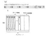
まず、アプリケーション処理モジュール4で、例えば図3のようなアプリケーションデータが生成される。アプリケーションデータの長さは、アプリケーションに依って異なり、一般的には広いレンジを持つ可変長のデータである。アプリケーションデータの発生間隔もアプリケーションに依存し、連続する場合や断続的、断片的な場合など様々なケースが考えられる。
【0075】
アプリケーション処理モジュール4tは、インタリーバモジュール8tに対してアプリケーションデータ(AAL−IDU)を渡していくが、1アプリケーションデータが終了した時点で、その旨をデリミタとしてインタリーバモジュール8tに通知する。
【0076】
(B)インタリーバモジュール8tによる処理
インタリーバモジュール8tは、アプリケーション処理モジュール4tから渡されたアプリケーションデータであるAAL−IDUを、マトリクス状メモリであるインタリーバのデータ領域の部分に順次書き込んでいく。書き込み方は、例えば図4の様に左上端から垂直方向に1列ずつ行う。
【0077】
インタリーバへの書き込みの方法として、ここでは図4に示した方向、順序に従う例を挙げるが、図5に示すような方法など、様々な書き込み順序、方向が可能である。
【0078】
FEC冗長領域内にはデータは書き込まず、書き込み終了後に各行のシンボルごとに対して予め決まった演算を行った結果を、対応するFEC冗長領域内の各行に書き込む。なお、演算を行った結果をメモリ内のインタリーバ領域に具体的に書き込まずに、論理的に別のメモリに格納し必要に応じて読み出し下位レイヤに渡すという方法も可能である。
【0079】
インタリーバのサイズは様々なものが考えられるが、例えば、AAL1では以下のようなサイズのインタリーバがオプションとしてITU−T勧告I.363によって標準化されている。横(列)のサイズとしては、1シンボルが1オクテットであって、データ領域124シンボル、FEC冗長領域4シンボルである。この場合の縦(行)のサイズは、セル長からSARヘッダ長を差し引いた長さ、47オクテットである。また、AAL1でのオプションの他の値として、同じシンボルサイズで縦のサイズが8シンボル、横のサイズがデータ88シンボル、FEC冗長領域6シンボルであるものも標準化されている。ただし、ここではこれらの値にこだわる必要はない。
【0080】
本実施例において、いくつかのインタリーバサイズの値を提示しているが、これらはいずれも、インタリーバがデータ領域としてとることのできる最大値を示している。すなわち、アプリケーションデータのサイズによって、それよりも小さく変化させることが可能である。アプリケーションデータのサイズがインタリーバの横のサイズを最大値まで用いた場合でも、その領域に入らないときには、2枚目のインタリーバ、3枚目のインタリーバと言うように、AAL1でのCBR転送と同じように複数枚のインタリーバを用いて転送することとなる。また、縦のサイズはセルのペイロードのサイズとの関係でいくつか実装に適当なサイズがある。
【0081】
例えば、インタリーバの1列に対して1つのSSCSヘッダ/トレイラとAAL5のCPCSトレイラを付与する方法をとったものとする。この場合には、縦の長さはセルのペイロード長からSSCSヘッダ/トレイラ分(ヘッダ/トレイラ部分によるオーバーヘッドをなるべく小さくするように、1オクテット等が考えられる)とCPCSトレイラ分(8オクテット)を除いた長さ(48−1−8=)39オクテット等が考えられる。また、1列を複数セル、例えば2セル分とすれば縦のサイズは(39+48=)87オクテット等が適当であると考えられる。
【0082】
縦のサイズが大きい場合と小さい場合を比べてみる。上述したものと同じ、インタリーバ1列をペイロードに持つSSCS−PDUについて比較すると、SSCSヘッダ/トレイラ長が同じならば、縦のサイズの大きい方が上位レイヤデータの転送効率(packing efficency)があがるという利点がある。一方、縦のサイズが長いと転送すべきデータが列の途中で終了してしまう可能性も高く、その場合にはその列の残りの部分をパディングで満たさなければならず、逆に転送効率が下がってしまうという問題点もある。縦のサイズとして適当な値を選ぶには、このようなトレードオフを加味すべきである。さらに、あまりに大き過ぎると、ランダムなビット誤りを含み易い問題あるいはFEC符号のオーバーヘッドが上がる問題などが生じる。
【0083】
横のサイズに関しては、従来と同じ誤り訂正符号として1シンボルがnビットのリード・ソロモン符号(以下RS符号と記す)を用いるとして、通常、最大長が(2^n)−1シンボルに限定される。拡張RS符号を利用すると、それよりも1あるいは2シンボル長いものも可能であるが、拡張RS符号は通常のものと比較して、受信後の復号処理、誤り訂正処理が複雑である。従って本実施例では、あえて拡張RS符号を用いないこととする。nの値としては、ソフトウェアによる処理の容易さも考慮して、8またはその倍数を用いることが一般的である。
【0084】
図6に一例を示すように、上記の値を越えない範囲で、インタリーバのサイズとして、横のサイズを4オクテットの倍数にする方法がある。この方法では、例えばRS符号で1シンボルをnビットとしたときに、nと列シンボル数との積が32の倍数になることを意味している。FEC機能をソフト処理で実現する場合を想定すると、計算機で仮想的にインタリーバへのデータの書き込み、読み出しを行うことになるが、計算機のCPUはメモリへのアクセスが4オクテット単位の方が扱いやすいので、有効なデータが足りない場合には4オクテット単位になるようにパディングをしてでもアライメントをとった方が良い場合もある。
【0085】
後で詳しく述べるが、今度はCPCSトレイラをデータ領域とFEC冗長領域の各々に1つずつ付ける例を考える。この場合、インタリーバの縦の長さはSSCSヘッダ/トレイラ分のみを考慮すれば十分である。よって、SSCSレイヤのオーバヘッドを例えば1オクテットとして、(48−1=)47バイトが良いと考えられる。しかしこの方法では、CPCSトレイラによって増加する8オクテットの増加分もセルのペイロードとして伝送しなければいけないことを考慮していないので、そのための8バイト分をインタリーバのデータ領域内に確保する方法か、あるいはCPCSレイヤのアライメントをとる機能に任せる方法のいずれかをとる必要が生じる。CPCSレイヤのアライメントをとる機能に任せる場合には、CPCSトレイラのみを1セルに格納することになるので40バイトのパディングが必要となり、オーバーヘッドが大きくなってしまう問題点がある。従って、インタリーバのデータ領域にあらかじめCPCSレイヤ用に8オクテットのスペースを確保しておく方がパッキング効率は良い。
【0086】
前述したように、データ転送の場合、AAL−IDUのサイズは一定でなく、SSCSモジュール6tではこのサイズを認識し、さらに受信側SSCSモジュール6rにも知らせる必要がある。多くのプロトコルでは、SSCSモジュール6tでAAL−IDUの終了(デリミタ)を検出することができ、SSCSレイヤでは予めサイズを認識することが可能となっている。従って、送信側のSSCSレイヤにおいてインタリーバのどの位置までデータを書き込んだかを、何らかの手段で明記し受信側SSCSレイヤにわかるようにしなければならない。
【0087】
次に、これまで述べてきた種々の例に基づいて任意のサイズのAAL−IDUをインタリーバに格納していった最終的な様子をいくつかの例について説明する。これらの例では、あらかじめコネクション毎に用いるインタリーバの最大サイズ、FEC領域の大きさ、SSCS−PDUの大きさやフォーマットなどが呼設定時にネゴシエーションされているものとする。
【0088】
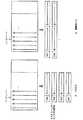
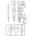
図7には、インタリーバの縦のサイズが39オクテットである例を示した。このサイズは、1列ごとに対して1オクテットのSSCSヘッダ/トレイラ(図7(b)のようにヘッダを付与している)とCPCSトレイラが1つずつ付いている例である。インタリーバの最大列数は128オクテットであり、各行に4オクテット分のFEC領域がある。
【0089】
また、この例は比較的大きなサイズのアプリケーションデータが格納された様子を示しており、複数枚(#1から#Nまで)のインタリーバに渡っている。もちろん、小さなサイズのアプリケーションデータであっても、図7に示したインタリーバの状態と同じように格納できる。図7(a)の#1は、データ領域がこの例で許容される最大値まで使用されているインタリーバであり、最後の1オクテットを用いてその列に含まれている有効なデータ量を長さ表示(LI)フィールドに表示する。また、図7(a)の#Nはデータ領域に未使用部分が残っている(アプリケーションデータが途中で終了した)インタリーバであり、最終列はパディングを含む場合もある。このインタリーバでも同様に最終列の最後の1バイトを用いて、その列の有効データ量をLIフィールドに表示する。よって、最終列の有効データ長とLIフィールドの1オクテットの和が39オクテットに満たない場合、その足りない分だけパッドを付加する。
【0090】
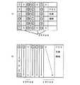
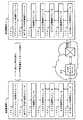
次に、図8に、インタリーバの縦のサイズが47バイトである例を示す。図9には、この場合のSSCSレイヤの処理の流れを説明するための図を示す。
【0091】
AAL−IDUが到着すると(ステップS11)、インタリーバへの書き込みを行う(ステップS13)。
【0092】
インタリーバが満たされると(ステップS14)、必要に応じてPADを挿入し、LIを書き込む(ステップS15)。そして、FEC冗長コードの計算を行う(ステップS16)。
【0093】
インタリーバからは、順次、列ごとのデータが読みだされ、SSCSヘッダが付与される(ステップS17)。
【0094】
そして、CPCS処理(ステップS18)、SAR処理(ステップS19)が行われ、ATMヘッダが付与され(ステップS18)、ATMセルとしてATM網を転送される。
【0095】
さて、図8は、インタリーバのデータ領域とFEC領域それぞれに対して1つずつCPCSトレイラが付与されている例である。図7の例と同じように、各列に対しては、1バイトのSSCSヘッダ/トレイラが付与される(図8(b))。また、この例も比較的大きなサイズのアプリケーションデータが格納された様子を示しており、複数枚のインタリーバ(#1〜#N)に渡っている。もちろん、小さなサイズのアプリケーションデータであっても、図8に示したインタリーバの状態と同じように格納できる。
【0096】
図8(a)の#1は、データ領域が最大値まで使用されているインタリーバであり、最後の9バイトを用いてその列に含まれているパディングの量をLIフィールド(1オクテット)に表示し、残り(8オクテット)は未使用とする。この8オクテットCPCSトレイラが付与される際に余分なパディングを行わなくてすむように、予めトレイラのサイズ分を確保しておくための領域である。また、図8(a)の#Nは、データ領域に未使用部分が残っている(アプリケーションデータが途中で終了した)インタリーバであり、最終列はパディングを含む場合もある。このインタリーバでも同様に最終列の最後の1バイトを用いてその列のパディングの量をLIフィールドに表示する。よってパッドは、最終列の有効データ長とLIフィールドの1オクテットの和が47オクテットに満たない場合、その足りない分だけ付加される。
【0097】
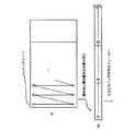
次に、図7と図8で用いられているLI表示の方法について詳しく説明する。図10には、その例を示した。(a)は図7に対応する場合で、データ領域内の途中の列の最下行でアプリケーションデータが終了した場合を表している。この場合最終列には有効なデータは含まれていないので、LIフィールドは0となり、38オクテット分のパディングをする。また、(b)は図8に対応する場合で、アプリケーションデータを書き込んでいって終了した行が38〜47オクテット目であった場合の表示方法を示している。この時は、LIフィールドにはパディングの量を示すようにする。この様な方法をとることで、送信側から受信側に正確にアプリケーションデータの量を伝えることが可能となる。
【0098】
同じアプリケーションのデータであれば、複数のAAL−IDUを1つのインタリーバ内に格納することも可能である。よって、1つのAAL−IDUのデリミタ検出後に、タイマを起動させ、ある一定時間次のAAL−IDUが到着するまでそのインタリーバの送出を待つこともできる。
【0099】
タイマーの設定は、アプリケーションがどれくらいのレイテンシを要求するかによっても様々な設定が可能である。例えば、遅延に対する要求条件の厳しくないファイル転送等では数秒待つことも可能であり、またそれとは逆で、動画像などの場合にはタイマーのしきい値を0に設定し帯域を最大限まで使用することもできる。
【0100】
アプリケーションデータをデータ領域に書き込んだ後には、レイテンシイを小さく抑えるためにも、できるだけ速やかにFEC冗長領域を計算することが望ましい。
【0101】
図11に一例を示すように、インタリーバからの読み出しは書き込んだ方向、順序と同じに、1シンボル書き込み終了後引き続いて1シンボル読み出しをすぐに行う。書き込みと読み出しを交代に、または並列に行うことによって、今まで書き込み終わるまで読み出しができなかったというボトルネックが解消され、SSCSレイヤの上位レイヤから下位レイヤに渡すまでにかかる時間が大きく減少する。データ読み出し後は、順次SSCSヘッダ/トレイラ付与モジュール12tへ渡していく。
【0102】
以上のように行うと、インターリーブにより生じていた遅延がほとんど無視でき、SSCSレイヤがヌルの場合とかなり近い速度が得られる。以前のインタリーブでは、書き込みは水平方向に、読み出しは垂直方向にと、1つのデータ領域内全てにデータが書き込まれてから(全てが埋まらない場合にはPADをしてから)読み出しを行っていた。これに対して本実施例の方法では、下位レイヤに渡すデータの読み出し方向を書き込み方向と同一にし、特にデータ領域に関しては書き込みと読み出しがほぼ同時に行われるので、データ領域全てを書き込むまでデータの送出を待たなくてもよくなり、遅延がかなり小さくなる。
【0103】
(C)FEC付与モジュール10tによる処理
FEC付与モジュール10tでは、図12に例を示すように、データ領域の範囲内に書き込まれたデータの各行に対して、それぞれのFEC冗長領域を計算し対応する位置に書き込んでいく。n行目に対するFEC冗長領域は、n行1列、n行2列、・・・、n行m列のm個のシンボルを用いて演算することによって得られた結果である。
【0104】
パディングがなされていないインタリーバの場合は図12(a)のように、また、インタリーバの途中でデータが終了している場合は図12(b)のように未使用部分を除いて各行に対応するFEC冗長領域を計算していく。(b)の場合に、n行目に対するFEC冗長領域を計算するには、n行1列からn行4列までのシンボルを用いて、未使用部分が無い場合と同じ演算方法でFEC冗長領域を計算することが可能である。
【0105】
図13に、1列が1つのCPCS−SDUとなる場合の例を示す。インタリーバは、AAL−IDUであるデータが書き込み終わったら、図13(a)のように、その列の残りの部分をPAD(例えばシンボル中のビットがall“0”またはall“1”)で埋めて、さらにその列の最後の1シンボルの部分に、その列に含まれる有効なデータの長さを書き込む。もし、ある列の最後までデータが埋まっていたら、図13(b)のように、次の列を使って長さ表示を行う。要するに、列の最後に長さ表示が含まれている列の前の列はデータで満たされることになる。
【0106】
データが全く書かれていない残りの列に対しては、PAD等は行なわない。データ領域の最後は次のステップで付与されるSSCSヘッダ/トレイラで受信側が認識できるので、余分なPADをしてインタリーバの最大サイズに合わせる必要はない。また、データを書き込んでいない部分はセルとなって転送されることもない。この様な操作を行うと、CBR転送に適していたインタリーバをデータ転送にも容易に適用することが可能となるのである。
【0107】
FEC冗長領域を計算する際、データが書き込まれていずダミーの入っていないデータ領域の各列はFEC冗長コード演算のために代入するパラメータが存在しないので、演算数が少なくて済むことになる。しかしながら、ダミーとして0または1がパディングされていて、しかもそれをFECの計算のためのデータとして用いる従来の場合には、その値を用いてデータがある列と同様の計算を各シンボルに対して行わなければならないので、データ領域が有効なデータで満たされている場合と同じだけの計算時間が必要になってしまう。したがって、残ったデータ領域にPADを入れず、かつその領域をFECのための演算領域からはずす場合は、演算量が減少するため簡単に短時間でFEC冗長の計算が行えることになり、より高速にプロトコル処理できることになる。
【0108】
図13は、データを書き込むという観点から、仮想的にインタリーブ行列をおいて、そこに左上から書き込む様子を示しているが、FECのための冗長を演算するような立場からは、実際には図14のように書かれていることと等価になる。すなわち、マトリクスの左側(すなわちFECのための情報部分の上位の方)はダミーのPADがつけられていて、データ領域の右端につめられて実データが置かれている構成である。実データ領域の中では、番号の若い(すなわち早く上位レイヤから来た)データほど左側にある。すなわち、FEC演算をする符号語、という点からは、下位の実データ分の情報部分とFEC冗長部分とがあるように見える。この様子を、図15(a)に示す。
【0109】
他には、例えば図16の様にデータが全く入らない列にダミーデータを入れてFEC冗長領域を計算するが、それらを含むダミーセルは送出しない方法もある。網に送出されるデータ量は図13の場合と同様に最低限に抑えることが可能である。
【0110】
それ以外にも、前述した図5(a)のようにシンボル毎にインタリーブのデータ領域中にランダムに配置したり、図5(b)のように行の順序をデータ領域の中で自由に設定することも可能である。これらの場合、同様にデータの全く入らない列にいれたダミーデータ列は送出しないことにより、網の送出されるデータ量はやはり図13や図16と同じく最低限に抑えることが可能である。
【0111】
これらの例では、あらかじめ通信前に送受信双方でインタリーブ行列への挿入方法についてあらかじめネゴシエーションしておくことは言うまでもない。
【0112】
図16および図5は、図13とは異なり、FEC演算の立場から見たインタリーブマトリクス構造はそれぞれの図と同一である。すなわち、各符号語は、図16の場合は、図15(b)にあるように、上位に実データの情報、その下にダミーの(シンボル値0の)情報があるような情報部分とFEC冗長部分とから構成される。また、図5(b)のようにランダムに実データ列を配する場合は、図15(c)のように実データとダミーデータがまだらに入ったような情報部分と、その右側の冗長部分から成る。
【0113】
図13、図16および図5共に、実データ部分はセルとして伝送されるが、ダミー部分は送出されない。受信側では、ダミー部分には0が送信されたものとみなして復号が行われる。
【0114】
図13および図16に関するFEC冗長領域の作成方法については、後でより詳細に説明する。以下のプロトコル処理の流れでは、代表例として図13のインタリーブマトリクスへの書き込み方法であるものとして説明を行う。
【0115】
FEC冗長領域を演算し始めた時には、データ領域に一度書き込まれたデータはSSCSヘッダ/トレイラを付与するためにSSCSヘッダ/トレイラ付与モジュール12tにほとんど渡されている(図11)。図7および図8のように、FEC冗長領域に書き込まれた計算結果も、演算終了次第、データ領域と同様に列方向に1列ずつ読み出され、SSCSヘッダ/トレイラ付与モジュール12tへと順次渡されていく。FEC冗長領域の計算にかかる時間は、一般にデータを水平方向に書き込むのを待つ時間よりもはるかに小さいことがわかっている。
【0116】
(D)SSCSヘッダ/トレイラ付与モジュール12tによる処理
SSCSヘッダ/トレイラ付与モジュール12tでは、インタリーバモジュール8tから列単位で読み出されたデータに対して、SSCSヘッダ/トレイラを付与しCPCS処理モジュール14tに渡していく。SSCSヘッダ/トレイラを付与する単位は、図17(a)のようにインタリーバの1列ごとでもよいし、図17(b)のように、一定の列数ごと、例えば2列ごとをひとまとめにしたものなども考えられる。すなわち、インタリーバの複数列にSSCSヘッダ/トレイラを付与したものがSSCS−PDUとなる。複数のインタリーバ列をSSCS−PDUとする場合には、ひとまとめとする列数が最低限FECの訂正能力を越えないようにする。FEC方式の誤り訂正では、付与している誤り訂正符号のオーバーヘッド(冗長部分)の量によって、訂正できるシンボル数(インタリーバの列数)に限界がある。例えば、前述の図8におけるインタリーバのFEC冗長領域の列サイズが4の場合には、データとFEC領域全体に対して、4列までの消失誤りを訂正することができる。
【0117】
ここで付与するSSCSヘッダ/トレイラには、それが付与されているデータ列がインタリーバのどの位置(何列目)にあったかを確実に特定するための情報が含まれていなければならない。
【0118】
代表的なFECを行う誤り訂正符号としては、Reed−Solomon符号があるが、この誤り訂正符号を用いて容易に訂正するための前提として、「誤り位置が特定されていること」という条件がある。もし、誤り位置が特定されていない場合、その位置特定のための計算量を多く必要とし、また、訂正能力も位置特定時のおよそ半分のシンボルエラーしか訂正できない。誤り位置(ここでは誤りが生じているデータを含むセルのインタリーバ内の位置に相当する)を特定するには、何らかの形で送信時にセル毎の識別子を付けておく必要がある。その識別子として最も有効であろう方法は、例えばセル単位にSNを付与することである。また、SNにもある程度の信頼性を持たせる必要がある。
【0119】
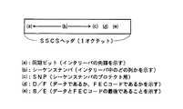
SSCSヘッダ/トレイラとしては、例えば図18のようなフィールドを持たせることができる。ここでは、1バイトの長さのヘッダの例を示している。
【0120】
インタリーバの横のサイズの一例として、CPUを用いてのソフト処理のためには、データ長を該CPUがアクセスする単位として4バイトにアライメントすることが望ましいことを前述したが、ここでも同様のことが言え、ヘッダ/トレイラ長を4バイトとすることも可能である。
【0121】
ここで、図18のSSCSヘッダの一例について説明する。
【0122】
(a)は、同期ビットであり、インタリーバの先頭のSSCSヘッダ/トレイラであることを示す。例えば、先頭の時は“1”、それ以外は“0”と表示する。
【0123】
(b)は、シーケンスナンバであり、インタリーバ中の順序を表示する。例えば、セル廃棄された時の抜けが検出できる。
【0124】
(c)は、SNP(Sequence Number Protection)ビット、すなわちシーケンスナンバに対するプロテクトのためのパリティビットであり、シーケンスナンバの誤りを検出する。
【0125】
(d)は、D/F(Data/Flag)ビットであり、ペイロードの中身がデータであるかそれともFEC冗長コードであるかを示す。
【0126】
(e)は、B/E(Begin/End)ビットであり、データとFEC冗長コード領域各々の最後であることを示す。例えばインタリーバ内で、データ領域およびFEC冗長領域の最後にあたるSSCSヘッダ/トレイラのこのフラグを“1”、それ以外を“0”に設定する。
【0127】
インタリーバからは、データ領域に引き続いてFEC冗長領域が読み出され、SSCSヘッダ/トレイラ付与モジュール12tに渡されてくる。SSCSヘッダ/トレイラの付与は、これらのデータ列に対して、上述したようなヘッダ/トレイラを一定間隔に挿入していくことで実現される。ここでいう一定間隔は、インタリーバにおける1列分の長さであったり、もしくは複数列分の長さである。
【0128】
図19には、インタリーバ1つ分に対するSSCSヘッダ/トレイラの例を示す。ここで示した値は、誤りの無い正しいSSCSヘッダ/トレイラの一例である。
【0129】
同期ビットは、インタリーバの先頭にあるSSCS−PDUを示し、シーケンスナンバはこの場合4ビットで循環している。図19の例では、シーケンスナンバはデータ領域に付与されている最初のSSCSヘッダ/トレイラを0としてスタートし、16を法として増加しており、データ領域の最後のSSCSヘッダ/トレイラとFEC冗長領域の最初のSSCSヘッダ/トレイラは連続している。また、別の方法としてFEC冗長領域の最初のSSCSヘッダ/トレイラでシーケンスナンバをクリアし再度0からスタートさせた場合でも実現は可能である。ただし、シーケンスナンバを途中でクリアせずに図19の例のように連続していた方が、データ領域とFEC冗長領域の境界でセル廃棄が生じた場合もセル廃棄の検出が容易に行えるという利点がある。また、1つのAAL−IDUのサイズがかなり大きく、複数のインタリーブに渡って格納される場合に対しては、連続したインタリーブ間に連続したシーケンスナンバを付与する方法と、データ領域の先頭のSSCSヘッダ/トレイラには必ず0を付与する方法との2通りが考えられる。データ領域の列数は固定長でないが、SSCSヘッダ/トレイラの別のフィールド(D/FビットやB/E)の表示や、FEC冗長領域のサイズが予めエンドエンド間でネゴシエーションされていることから、データ領域とFEC冗長領域が交代して転送されてくる境界を正しく識別することが可能である。
【0130】
シーケンスナンバプロテクトは4ビットのシーケンスナンバに対して偶パリティを計算するものとする。もちろん、その代わりに奇数パリティを用いても構わない。
【0131】
本実施例では、D/Fビットは1であればインタリーバ内のデータ領域であることを示し、0であればFEC冗長領域であることを示している。B/Eビットは、ENDを1として、データ領域のSSCS−PDUの最後のPDUとFEC領域のSSCS−PDUの最後のPDUにマークをしている。
【0132】
図19で示したSSCSヘッダ/トレイラで、B/Eフィールド=1,D/Fフィールド=データ、の値を持つヘッダ/トレイラが、そのインタリーバのデータ領域の最終列に含まれる有効なデータ長を示すLIフィールドを含むSSCS−SDUに付与される。
【0133】
(E)CPCS処理モジュール14tの処理
順次CPCS処理モジュール14tに渡されたデータには通常のAAL5処理が行われ、長さ表示とCPCSトレイラが付けられる。CPCS−SDUとなる単位の例として、図7と図8の2種類を挙げる。図7では、SSCSヘッダ/トレイラとそのペイロードが1組となったものが、CPCS−SDUとなる単位である。図8では、インタリーバのデータ領域とインタリーバのFEC冗長領域のそれぞれ(合計2つ)が、CPCS−SDUとなる単位である。
【0134】
図7の場合は、インタリーバの1列ごとにSSCSヘッダ/トレイラを付与する方法をとり、それぞれに対してAAL5のCPCSトレイラが付与される。この方法ではAAL5のCRCがインタリーバの一列に対して適用されるので、もし受信側でエラーが発見された場合には、該インタリーバの特定の一列にエラーのあることが認識される。また、もしセル廃棄が発生したとしても、SSCSヘッダ/トレイラにおけるシーケンス番号の抜けから、どのインタリーブ列が受信側に到着しなかったかを把握できるようになっている。このようにして、セル廃棄やビット誤りの位置を正確に特定することが可能となる。
【0135】
図7の応用として、インタリーバの1列ではなく、複数列毎にSSCSヘッダ/トレイラを付与する方法もある。図7ではSSCSレイヤのオーバヘッドとインタリーバデータの一列とCPCSトレイラの和が例えば48オクテットになるようにインタリーバを設計して、レイヤ毎に余分なパディングを防ぐような工夫をしている。これを応用した場合においても、インタリーバの縦の長さを工夫して、SSCS−PDUの長さとCPCSトレイラの長さの和が48オクテットの倍数か、あるいはそれが通信を行う端末の操作上不可能な場合でも、なるべくCPCSレイヤでのパディングを少なくするような設計が、データ転送効率をあげる上で望ましい。
【0136】
図8の場合は、AAL5トレイラも1つのインタリーバに対して2つだけ付与する方法をとる。2つとは、データ領域全体に対して1つのCPCSトレイラを付与し、FEC冗長領域全体に対してもう1つのCPCSトレイラを付与することを意味している。前者については、パディングを最小限にするために、予めインタリーバモジュール8tでインタリーバのデータ領域の最後の8バイト分は未使用にしてあるので、SSCSレイヤから渡されたデータにCPCSトレイラを付与すると、ちょうど48バイトの倍数になり、SAR処理を行うときにパディングの必要がなくなる。一方、FEC冗長領域に対してCPCSトレイラを付与する場合には、予めインタリーバモジュール8tで未使用部分を確保しておくことができないので、図8のようにインタリーバの一列を47オクテット長とした場合には、40オクテットのパディングが必要になってしまう。しかし、例えば図7と比較して、AAL5のトレイラ数が少ない分のオーバーヘッドを小さくすることができ、転送効率があがることになる。また、上記パディングを減らしたい場合には、例えば図8において、インタリーバの長さを変更し、FEC冗長領域を含むSSCS−PDUとCPCSトレイラの長さの和を48オクテットで割った余りが0であるかあるいは、48オクテットに十分近い値であるようにすることも可能である。詳しくは、受信側のSSCSヘッダ/トレイラ確認モジュール12rの説明において述べる。
【0137】
(F)SAR処理モジュール20tによる処理
SAR処理モジュール20tでは、CPCS処理モジュール14tから受け取ったデータ(CPCS−PDU)のセグメンテーション処理が行なわれる。ただし、インタリーバの縦のサイズ、SSCSヘッダ/トレイラのサイズ、CPCSトレイラのサイズの合計が48オクテットになっていれば、セグメンテーションは行なわれない。一方、例えば、CPCS−PDUが図8のようになっていて、CPCSトレイラがデータ領域、FEC冗長領域のそれぞれに対して1つずつ付与されているような場合には、セグメンテーションが行われる。
【0138】
48オクテットに区切られたSAR−PDUは、ATMヘッダ付与モジュール22tに渡される。その際、ATMヘッダ付与モジュール22tに渡されるSAR−PDUがCS−PDUの最後部にあたるデータである場合、その旨をATMヘッダ付与モジュール22tに通知する。
【0139】
(G)ATMヘッダ付与モジュール22tによる処理
ATMヘッダ付与モジュール22tでは、呼設定時に定められたATMセルヘッダを付与した後、物理レイヤの処理を介して、ATMセル化されたデータをATM網1に対して送出する。SAR処理モジュール20tからデータ(SAR−PDU)を受け取る際、これはCPCS−PDUの最後部である旨の通知を受けている場合は、ATMセルヘッダのペイロードのUUIフィールドに、これを告げる旨のビットを立てておく。
【0140】
以上が、送信側端末2tにおける処理の流れである。
【0141】
次に、受信側端末2rにおける処理をレイヤの昇順、すなわち各処理モジュールの動作する順に従って説明する。
【0142】
(H)ATMヘッダ削除モジュール22rによる処理
ATMヘッダ削除モジュール22rでは、ATM網1から受け取ったセル流について、物理レイヤ処理を行った後に呼設定時に定められたATMセルヘッダを有したセルを受け取った場合、これをフィルタリングして受け取り、その他のセルは無視し、ATMセルヘッダを削除してSAR処理モジュール20rに渡す。ここで、ATMセルヘッダのペイロードタイプのUUIフィールドに、CPCS−PDUの最後部であることを示すビットが立てられていたらその旨をSAR処理モジュール20rに対して通知する。
【0143】
CPCS−PDUの最後部を構成するセルであることを示すビットを含むセルが廃棄された場合、図20のように、次に到着するCPCS−PDUと同一のCPCS−PDUとして上位レイヤに渡されてしまう。しかしながら、CPCSトレイラのチェックによりこの誤りは検出される。さらに、その誤りを含むCPCS−PDUをSSCS処理モジュール6tまで渡すことで、FECを用いて訂正することが可能なのである。
【0144】
(I)SAR処理モジュール20rによる処理
SAR処理モジュール20rでは、ATMセルヘッダ削除モジュール22rから渡されたデータ(SAR−PDU)に対し、CPCS−PDUの最後部であるという表示を参照してデータのアセンブリを行う。アセンブリ終了後、CPCS処理モジュール14rに該データが渡される。
【0145】
(J)CPCS処理モジュール14rによる処理
CPCS処理モジュール14rでは、SAR処理モジュール20rから受け取ったCPCS−PDUに対し、AAL5の処理であるCRC演算処理、および長さ表示の確認を順次行う。
【0146】
ここで、CRC演算処理、および長さ表示の値のいずれかに誤りが検出されたかどうか、結果をSSCS処理モジュール6rに通知する。この場合、どちらの演算で誤りが生じたかを知らせる必要は必ずしもない。
【0147】
(K)SSCSヘッダ/トレイラ確認モジュール12rによる処理
SSCSヘッダ/トレイラ確認モジュール12rでは、主にSNに抜けがないか、さらに、CPCSトレイラで誤りが検出されている場合にはその通知を受け取る等の確認しながら、ヘッダ/トレイラを取り除いていく。
【0148】
CPCSトレイラで誤りが検出されていることを通知されている場合には、そのCPCS−PDUに含まれるSSCS−PDUのいずれかが廃棄されている可能性が高いので、SNをチェックしセル廃棄の位置を特定しなければならない。
【0149】
SSCSヘッダ/トレイラの誤り(ビット誤りも含む)としては様々な状況が考えられる。ここでは、図18の例に示したフィールドを持ったヘッダ/トレイラの誤りの対処について説明する。
【0150】
(a)の同期ビットはインタリーバの先頭を示すビットである。そのSSCS−PDUがインタリーバの先頭のデータを含んでいる場合にはそのビットをたてて1とし、その他の場合には0とするものである。もし、この同期ビットが反転してしまうような誤りが起きた場合には、そのSSCS−PDUから新規のインタリーバであることがわからないかも知れない。しかし、その前のSSCS−PDUの(d)のFEC冗長コードである表示と(e)B/Eビットが最後であることを示していることによって、同期ビットが反転していても新規のインタリーバの先頭を検出することが可能である。
【0151】
(b)のシーケンスナンバでビット誤りが生じた場合には、その後の(c)のシーケンスナンバプロテクション(例えば、偶数パリティ)を用いて誤り検出することができる。前後のシーケンスナンバが正しいことがわかれば、ヘッダ/トレイラを取り除いた後、SSCSのペイロード部はインタリーバの相当する位置に書き込むことができる。また、その代わりに、疑わしいデータを廃棄してしまってセル廃棄と見なしてFEC冗長コードを用いて正しいデータを再生させることも可能である。
【0152】
(d)のD/Fは、ペイロード部が含むビット列がデータであれば1、FEC冗長コードであれば0というように、ペイロードのタイプを示す。また、(e)のB/Eは、データを含む複数の連続したSSCS−PDUの中でそのSSCS−PDUが最後であることを示す。FEC冗長部についても、同様に、連続したSSCS−PDUの中で最後であることを示す。従って、B/Eビットが1の(要するにそのSSCS−PDUが最後のデータである)場合に、この表示がビット誤りを起こしたとする。しかし、次のSSCSヘッダ/トレイラのD/Fビットが1から0になり、そのペイロードにはFEC冗長コードを含むことが知らされるので、SSCS確認モジュール12rでは正しく認識することが可能である。
【0153】
上記では、伝送路においてビット誤り率が例えば10^(−10)以下といった微小なネットワークであるような場合を想定していることから、該SSCSヘッダ/トレイラおよびその前後のSSCSヘッダ/トレイラには同時に2ビット以上のビット誤りが存在しないことを前提として記述をしている(ただし、^はべき乗を意味する)。しかしながら、実際には、極めて珍しいことではあるが、その範囲に2ビット以上の誤りが含まれることもあり、その場合には、例えば、インタリーバのFEC冗長領域の大きさが固定であることや、シーケンス番号が連続していること等、上記以外の条件を加味して正確なSSCSヘッダ/トレイラを再現することが可能である。さらには、該SSCSヘッダ/トレイラ全体の長さを例えば2オクテット長にし、その一部または全体を誤り訂正符号化することによって、ほぼ完全にビット誤り対策が施されることになる。
【0154】
次に、以上のような対誤り性を考慮した上で、具体例として図7と図8で示した送信データを受信した場合の処理について説明する。また、各々の場合で、CPCS処理モジュール14rからCPCSトレイラに誤りが検出された対処の方法について述べる。
【0155】
まず、図7の場合について説明する。
【0156】
この場合は、インタリーバ内の比較的小さな単位、例えば1列ごとに1つのSSCSデータについて、1つのCPCSトレイラが付与されている。それぞれの列に関してCRCおよび長さ表示を用いたチェックを行うことができるので、それらが正しい場合にはそれぞれのペイロード部の信頼性が保証され、ペイロードに含まれているSSCSヘッダ/トレイラの信頼性も保証されることになる。もちろん、CRCチェックによって漏れがあるような誤りパターンが存在しない訳ではない。しかしながら、そのようなパターンの発生確率は、該データに4ビット以上の誤りが発生し、かつ、その誤りパターンが偶然CRCチェックにより検出できないという、極めて微小なケースであり、これはこのレイヤの誤り検出レベルとしては、十分無視できる程度のものである。
【0157】
また、このCPCSトレイラの付与の方法では、セル単位にCRCが演算されることになり、セル内のビット誤りを検出することも可能となる。そこで、ビット誤りの検出されたセルを廃棄されたと見なすことによって、誤り位置不明のビット誤りを位置のわかった消失誤りの形で誤り訂正することができる。FEC符号では、位置不明のランダム誤りを訂正するよりも、位置のわかった消失誤りに対しての方がおよそ2倍の訂正能力があるため、この手法はより少ないFEC冗長部で同じ訂正能力を有することができるという点で極めて有効である。
【0158】
図7の応用として、インタリーバの数列に対してCPCSトレイラを1つ付加する場合を上述した。そのような場合に、もし1つのCPCS−PDUが1つのセルに入らない場合は、複数セルに対して、CPCSトレイラによるチェックが行われる。そのケースで、CRC等のチェックによってビットエラーが発見されたとすると、そのエラーがインタリーバの数列のどこにあるかがわからないため、該当するCPCS−PDUに属するインタリーバの数列全部を廃棄されたものとみなす方法と、位置の特定できないランダム誤りが発生したとして訂正を行う方法がある。もちろん、これらいずれの場合においても、訂正できるだけの十分なFEC冗長領域を有していることが必要である。
【0159】
図7において、1つのインタリーバに含まれるデータ領域を含む全てのCPCS−PDUに対してCPCSトレイラの誤りが全く通知されていない場合には、上述したように、該インタリーバのデータ領域には誤りがないと判断できる。この場合、SSCSヘッダ/トレイラ確認モジュール12rはそれらのデータに対して以下の手順で処理を行う。
【0160】
先頭SSCS−PDUから順にSSCSヘッダ/トレイラのD/FビットがDであることを確認しながら、デインタリーバモジュール8rに渡していく。CPCSトレイラで誤りが検出されていないので、デインタリーバモジュール8rのデータ領域に格納せずに、直接上位レイヤであるアプリケーションレイヤまで渡すように通知する。
【0161】
そして、データ領域に相当する部分を含む複数のCPCS−SDUより以降に到着する、FEC冗長符号を含むCPCS−SDUは廃棄するように命令を出す。というのは、もはや誤り訂正をする必要がないので、次以降に到着するFEC冗長領域のデータを含むCPCS−SDUは不要だからである。
【0162】
もちろん、SNのチェックを行い、セル廃棄が無いことを確認しながら、SSCSヘッダ/トレイラを取り除くことはいうまでもない。これらの処理は、SSCSヘッダ/トレイラ確認モジュール12rの基本動作である。よって、以下に説明するケースでも必ず行われる。
【0163】
次に、図7において、CPCS−PDUに誤りが検出された場合を考える。
【0164】
先頭のSSCS−PDUから順にSSCSヘッダ/トレイラのD/FビットがDであることを確認しながら、デインタリーバのデータ領域に格納するようにデインタリーバモジュール8rに渡していく。データ領域の最後の列を含むSSCS−PDUに付与されたヘッダ/トレイラはエンドビットがマークされており、更に次のSSCS−PDUはF/DビットがDからFに変わる。このPDUからは、FECを含むデータであることをデインタリーバモジュール8rに通知する。この通知に従って、デインタリーバモジュール8rは、データとFEC冗長符号をデインタリーバの正しい位置に格納していく。途中で生じているセル廃棄は、SSCSヘッダ/トレイラ中のSNにより廃棄されたセルの位置の特定が可能である。
【0165】
上記のようにデインタリーバ上に置かれたデータに関する誤り訂正の詳細については、デインタリーバモジュール8rによる処理の説明のところで行う。
【0166】
次に、図8の場合について説明する。これは、インタリーバ内のデータ領域とFEC冗長領域に対してそれぞれ1つずつのCPCSトレイラが付与されている例である。図21には、この場合の処理の流れを説明するための図を示す。
【0167】
ATM網から転送されてきたATMセルのATMヘッダを削除し(ステップS31)、SAR処理(ステップS32)、CPCSR処理(ステップS33)を行う。CPCS−PDUに対して行われたCRCおよび長さ表示チェックの結果がCPCS処理モジュール14rからSSCSレイヤに対して通知される。
【0168】
図7の場合と同様に、誤りが検出されていなければ、その旨の通知をSSCSヘッダ/トレイラ確認モジュール12rがCPCS処理モジュール14rから受けている。この場合には、次にFEC冗長領域を含むCPCS−PDUがCPCSレイヤから渡されたときには、誤りを含む含まないに係わらずそのCPCS−SDUを廃棄してよい。よって、図21で「FEC冗長コードの廃棄命令を出す」というオペレーションが動作し(ステップS35)、次に到着するCPCS−SDUを廃棄する(ステップS36)。このように処理を行えば、FECを付与していない場合と比較してもSSCSヘッダ/トレイラを削除するだけのオーバーヘッドで実現が可能である。
【0169】
すなわち、FEC冗長領域とデータ領域が別々のCPCS−PDUに属していることにより、上述したように、データ領域のCPCS−PDUにエラーのない場合に、FEC領域のSSCS処理を行う無駄がなくなり、結果として処理の軽減を図ることができるのである。これは、必ずしもデータ領域とFEC冗長領域に1つずつのCPCS−PDUを割り当てる場合にとどまらず、図7の例などにもあるように、1つのCPCS−PDU内に、インタリーバのデータ領域とFEC冗長領域が混ざって存在しなければ、同様にあてはまることである。
【0170】
次に、データ領域を含むCPCS−SDUにエラーが発見された場合について説明する。CPCSトレイラで誤りが検出されたデータ列の先頭に位置するSSCSヘッダ/トレイラの中を見て(ステップS34)、ペイロード内のデータ列がデータ領域を示している場合、すなわちD/FビットがDである場合、誤り訂正を行わなければならない(ステップS38,S40)。ペイロードの中身がFEC冗長領域、すなわちD/FビットがFである場合には、それとペアであるデータ領域を含むCPCS−SDUで誤りが検出されていなければ上述の例にあてはまるので、FEC冗長符号を含むCPCS−SDUはもはや不要であり、訂正の必要はない(ステップS39,S40)。
【0171】
先頭のSSCS−PDUから順にSSCSヘッダ/トレイラのD/FビットがDであることを確認しながら、デインタリーバのデータ領域に格納するようにデインタリーバモジュール8rに渡していく。データ領域の最後の列を含むSSCS−PDUに付与されたヘッダ/トレイラはエンドビットがマークされており、更に次のSSCS−PDUはF/DビットがDからFに変わる。このPDUからは、FECを含むデータであることをデインタリーバモジュール8rに通知する。この通知に従って、デインタリーバモジュール8rは、データとFEC冗長符号をデインタリーバの正しい位置に格納していく。途中で生じているセル廃棄は、SSCSヘッダ/トレイラ中のSNにより廃棄されたセルの位置の特定が可能である。
【0172】
しかしながら、図7の場合と異なり、通常のランダム誤りが含まれている場合、その誤り位置をインタリーブのどの一列あるいは数列であるかを特定することができない。従って、この場合は、位置のわからないランダム誤りが含まれることを前提とした誤り訂正処理を行わなければならない。
【0173】
このランダム誤り訂正は、一般に消失誤り訂正よりも処理量が多くなるため、それを防ぐための工夫を行うことができる。
【0174】
セル内に含まれるランダム誤り(位置のわからないビット誤り)を検出するためには、セル毎にセル全体に対するCRCを設けることが必要である。このようなCRCを設けるには、SSCSヘッダ/トレイラに含めることが適切であると考えられ、その場合には、SSCSヘッダ/トレイラは、図18に示した例よりも大きなサイズになる可能性もある。SSCSヘッダ/トレイラのCRCにより、あるセル内に誤りが生じていることが発見された場合には、そのセルは消失したものとみなし、デインタリーバにはそのセルは廃棄されたと通知する手段をとる。このように、ランダム誤りを消失誤りにみたてて訂正を行うことにより、処理量が多くなるのを避けることができる。
【0175】
ところで、受信側のCPCS処理とSSCS処理を協調動作させたソフトウェアで実現する場合には、さらなる高速化を図ることができる。すなわち、データ領域に対するCPCS処理時に行う通常の長さのカウントとCRC演算を同時に行うのと並行に、SSCS処理としてSSCSヘッダ/トレイラの削除を行うものである。
【0176】
このように行うと、CPCS処理で誤りが検出されなかった場合には、すでにメモリにはSSCSヘッダ/トレイラの取り除かれた状態で書き込まれているので、上位レイヤへの受け渡しがポインタ渡しで瞬時に行えるのである。もちろんこの後に渡されるFEC冗長領域を含むCPCS−SDUは、すでに不必要であるので廃棄して構わない。
【0177】
データ領域を格納したCPCS−PDUについてのチェックで誤りが検出されたならば、その旨をSSCS処理モジュール6rに通知し、続いてCPCS処理モジュール14rで処理されるFEC冗長領域を含むCPCS−PDUをチェックし、両CPCS−PDUをSSCS処理モジュール6rに渡さなければならない。SSCS処理モジュール6rでも誤りの検出された通知を受け、それに従いシーケンスナンバ等ヘッダ/トレイラのを確認し、セルの抜けている位置をデインタリーバに通知し誤り訂正をさせることとなる。
【0178】
(L)デインタリーバモジュール8rによる処理
デインタリーバモジュール8rでは、SSCSヘッダ/トレイラ確認モジュール12rからの情報により、データ領域に誤りがなければデータ列をインタリーバに書き込みしなおすことなく、スルーな状態でアプリケーション処理モジュール4rに渡していく。例えば図5のように、インタリーブ上ではランダムな並びであるようなデータもあるが、これらデータの送受信の順序は上位アプリケーションから見て順序透過性がある。すなわち、CPCSレイヤからのデータについて、SSCSレイヤでのオーバヘッドを除けば、そのままスルーしてアプリケーション処理モジュール4rに渡すことが可能である。
【0179】
SSCSヘッダ/トレイラ確認モジュール12rからの情報により、データ領域に誤りが検出されていれば、誤りを含むデータをインタリーバの所定の位置に戻していき、該データ領域に対応して付随されているFEC冗長領域のビット列をSSCSヘッダ/トレイラ確認モジュール12rから受け取り、同じくインタリーバのFEC冗長領域に戻し、FEC演算を行って誤り訂正を行う。
【0180】
この際、データ領域の最後のSSCS−SDUは全てがデータではなく、一部がダミーデータである可能性が高い。1列のどこまでがデータであるかは、SSCSヘッダ/トレイラによりデータを含む最後のSSCS−SDUであることを認識した結果を、デインタリーバまで通知してもらうことにより検出する。
【0181】
図8の場合、デインタリーバではデータ領域の最後のSSCS−SDUが到着したら、その列の最後から9シンボル目(LIフィールド)を見る。そこに示された値は、LIフィールドから逆方向に何オクテットのパディングが挿入されているかを示している。また、図7の場合には、データ領域の最終列の最後のシンボルがLIフィールドとなっており、そのLIフィールドから逆方向に何オクテットのパディングが挿入されているか、またはその最終列内の最上行から何オクテットの実データが含まれているかのいずれかの情報を表す。
【0182】
その後、データ領域に書き込まれている訂正されたデータをアプリケーション処理モジュール4rに渡していく。渡す順序は送信側端末2tでインタリーバモジュール8tに書き込んだ順序と同様に列方向に読み出しながら渡していく。デインタリーバ処理を行ってデータ長を正確に把握しているので、上位レイヤに渡す場合にもパッドのダミーデータを上位に渡してしまうことはない。データ領域のSSCS−PDUに誤りが検出されていない場合にも、上位にパッド以外のデータのみを渡さなければならないので、データの正確な長さを把握する必要がある。この場合は、FEC冗長コードの廃棄命令を出す際に、先に説明したデインタリーバを行った場合と同じようにデータ領域を含む最後のSSCS−SDUをSSCSヘッダ/トレイラ確認時に通知してもらい、それによって長さを正確に知る。パッドであった部分は上位レイヤに渡す前に取り除く。
【0183】
(M)アプリケーション処理モジュール4rによる処理
最後に、アプリケーション処理モジュール4rが、アプリケーションデータをSSCSヘッダ/トレイラ確認モジュール12rから受け取り、アプリケーション処理を行う。
【0184】
以上が、受信側端末2rにおける処理の流れである。
【0185】
次に、より具体的な例として、FEC付与モジュール10tおよびFEC訂正モジュール10rにおけるFEC手法の動作例をあげる。
【0186】
送信側において、FEC付与モジュール10tでは、インタリーバモジュール8tからのデータを見ながらインタリーバのFEC冗長領域に付加すべきデータを計算し、その結果をすぐにインタリーバモジュール8tに返す役割を担う。インタリーバモジュール8tでは、受け取ったFEC冗長領域用のデータを通常のデータに続けてSSCSヘッダ/トレイラ付与モジュール12tに渡す。SSCSヘッダ/トレイラ付与モジュール12tでは、それぞれの領域に従って、ヘッダ/トレイラを付与する。
【0187】
また、受信側において、FEC訂正モジュール10rは、そのインタリーバについて訂正する必要のある時のみ動作する。すなわち、下位のCPCS処理モジュール14rにおいてセル抜けやビット誤りによるエラーが検出された時、そのデータはSSCS処理モジュール6rに渡されてデインタリーバモジュール8rに蓄えられる。そして、SSCSヘッダ/トレイラ確認モジュール12rにおいて、多くの場合、デインタリーバ内のどの位置にセル抜けあるいはビット誤りがあるのかが検出される。プロトコル仕様によっては、位置の正確に特定できないビット誤りが含まれることがあるが、その場合でも、訂正能力は誤り位置の特定された場合よりも限定されるものの、FEC訂正モジュール10rにおいては訂正可能な構成をとることができる。しかしながら、この実施例では簡単のため、上記SSCSヘッダ/トレイラに付与された種々のビットが有する能力によって、ビット誤りが発生した場合においても、その誤りシンボル位置が特定できるものと仮定する。このようなエラーに対して、FEC訂正モジュール10rでは、デインタリーバモジュール8rのデータを参照しながら、データ抜け部分の復元、あるいはビット誤りの訂正を行う。そして、訂正情報をデインタリーバモジュール8tに戻す。
【0188】
FEC付与モジュール10tおよびFEC訂正モジュール10rの構成は、これまでに述べてきたインタリーバモジュール自身のサイズや、それぞれのインタリーバについて、1つのSSCSヘッダ/トレイラを付与する列数や、またインタリーバへの書き込み位置等によって、少しずつ異なることになる。
【0189】
従って、これらのモジュールの例を挙げる際には、インタリーバモジュール8tおよびデインタリーバモジュール8rと関連させながら説明することとなる。はじめに、送信側におけるFEC冗長シンボル構成法の例をあげ、その後にそれぞれの方法に対する、受信側での誤り訂正方法の例を述べることとする。
【0190】
まず、図7および図8に示されるようなインタリーバの一列がすべて1セルのペイロードに収容され、また該1列のみでSSCSレイヤのペイロードとなる場合について説明する。このような場合は、インタリーバの縦の長さは39オクテットまたは47オクテット、横の最大長はRS符号の1シンボルをkビットとして2^k−1シンボル長以下になる。このようにシンボルの大きさを可変にすると、それに従ってインタリーバの大きさが変わるが、これらインタリーブ処理には、主としてソフトウェア上での操作を考慮する必要があるので、ソフトウェア処理に適したインタリーバ長にするため、1シンボルのビット数は2のn乗(nは整数)、すなわち4ビット、8ビット、16ビット等が望ましい。また、この中で、AAL1では1シンボルを8ビットとした仕様が決められている。従って以下では、1シンボルは全て8ビットの場合のみについて記すこととする。もちろん、他のビット数の場合も同様の操作で行われる。
【0191】
そのようにすると、図7のような例では、インタリーバの縦の長さが39オクテット、横の長さが255オクテット長以下の任意のオクテット長となる。また図8では、横は同じで縦のみが47オクテットとなる。どちらの図でも、データ領域に最大124オクテット、FEC冗長領域に4オクテット分を割り当てている。実際にはこれらの合計が255オクテットを越えないように設計できることになるが、本実施例では、AAL1におけるインタリーバの横の大きさに合わせた例として、図7および図8の場合について詳細に示すこととする。従って、生成多項式等もAAL1と同様のものとして論じることとする。
【0192】
具体的には、αを8次の原始多項式の根とし、生成多項式は、
【0193】
図7および図8における実際のFEC演算の方法としては、図13および図14による方法、図16による方法、図5による方法等がある。
【0194】
以下、それぞれの方法を示す。
【0195】
(1)送信側FEC処理方法1
ここでは、図13や図14の送信側におけるインタリーバへのデータ挿入方法に対するFEC冗長データの生成方法を示す。
【0196】
図14にあるように、この方式の場合、インタリーバのなるべく右側につめてデータが挿入されていることが特徴である。従って、図7のインタリーバで具体的に説明すると、データがインタリーバのデータ領域に全部入っている場合には、39×124シンボル分のデータが入るが、もしデータがm列分しかない場合、インタリーバの左から(124−m)列は空(データがはいっていない)となる。そして、残りm列の先頭からデータが入るが、データ領域の最後の列は実データが全部入っている場合と、パディング用のデータの混じっている場合がある。
【0197】
データの入っていない先頭の(124−m)列に関しては、この部分をセルに合成して送信することはないため、FEC用の符号化をするに際しても、この部分は、符号化のための情報部に含めない。ただし、装置化するにあたって、送受信の少なくとも一方がインタリーバの大きさを可変長にすることが困難であるような場合があるかもしれない。そのときは、あらかじめ送受信間でネゴシエーションし、実際にはデータを送らないとしても、インタリーバの中で空きがでる部分にどのようなダミーデータをいれてFECの符号化および復号化を行うかについて決めておく方法もある。
【0198】
インタリーバについては、各行毎に符号化を行うこととする。この場合、mシンボル(オクテット)の情報部分と4シンボル(オクテット)の冗長部分からなる符号語が39行分できることになる。各行は並列に符号化/復号化が行われ、それぞれの行で同じ動作が行われるため、以下では一行のみについて示すこととする。
【0199】
インタリーバの一行には情報シンボルはm個(1≦m≦124)あるので、それをインタリーバの左側から表して、
【0200】
また、符号語のシンボルは(m+4)個あるので、それもインタリーバの左側から表すと、
【0201】
従って、上記(2)式と(3)式において、情報シンボルはそのまま符号シンボルとして使用し、
【0202】
このようにすると、送信時に、上位レイヤからのメッセージをそのまま下位に流すことができる。すなわち、一旦インタリーバに書き込むことなく、上位レイヤからのメッセージをスルーして流せるため、遅延が小さくて済むというメリットが生まれる。ただし、上位から下位へ流すデータは、冗長シンボル生成のための計算処理のためには使用される。
【0203】
一方、受信時にはデインタリーバのデータ領域の全体、あるいはその領域をいくつかに分割したそれぞれの部分に対して、下位レイヤにおいてCRCによる誤り検査が行われる。この検査の結果そのデインタリーバのデータ領域に誤りがないと判定された場合には、データ領域のデータは、SSCSレイヤにおいて、デインタリーバに改めて書き込むことなく、SSCSヘッダ/トレイラ処理のみを行ってスルーして上位レイヤに送ることができる。また、冗長部分は不必要なので、これも特に処理を行わず即座に廃棄できる。このようにして、受信側処理全体のスループットを向上させるというメリットがある。ところが、もし同じ値を元の情報と符号語とで共有している式(4)のような構成になっていなければ、符号語全体を受信しないと元のメッセージが復元できないため、上述のメリットが生まれないことになる。
【0204】
以上は、主として図14に関するインタリーバモジュール8t中のデータについて述べた。式(4)のようにして、C[m+3]からC[4]までは簡単に生成することができる。
【0205】
次に、残りの冗長部分の生成方法を述べる。この冗長部分は、上述した構成のインタリーバモジュール8tからのデータ受けて、FEC付与モジュール10tにおいて生成される。
【0206】
ここでは、AAL1と同じようなRS符号を用いることとしているので、演算としては、まず情報Mを多項式表現したM(X)を、
【0207】
ここで、Q(X)は、M(X)・X^4をG(X)で割った商にあたり、式(6)のQ(X)・G(X)以外の右辺部分は、その余りに相当する。よって、M(X)が決まると、式(6)の左辺をG(X)でわり算すればよい。a[m]、b[m]、c[m]、d[m]はそれぞれ、
【0208】
繰り返し述べているように、このインタリーバはある最大サイズまでは可変であり、しかもそれがどれ位の大きさになるかは、上位からのデータ量次第である。従ってデータが多い場合も少ない場合も同じような計算手法を使わないと、計算に無駄が生じることになる。式(6)をそのまま用いることは、M(X)が確定してからならばよいが、通常は上位レイヤからいきなりメッセージMを全部一度に与えられることはない。上位レイヤからは、例えば数バイト長ずつのデータが流れてきている。それを全部受け取った後に、はじめて上位レイヤからのメッセージ長がどれだけの量であった、ということが判明するのである。従って、もしM(X)が確定するまでFEC演算処理の開始を待つとすると、それは従来のAAL1のような垂直方向のデータの読み書きをする場合と同じ程度の遅延を要することになってしまう。そのような訳で、上位レイヤからデータが流れ始めると、すぐにFEC冗長領域の計算が開始でき、しかもいつ上位レイヤからのデータが終わったとしても、常に式(6)の形になっているような計算方法を用いる必要がある。
【0209】
そこで、本実施例においては、ハードウェアにおいて符号化に用いられているシフトレジスタを用いた方式を(ソフトウェアで実現する場合においても)採用するのがよい。すなわち、まずM[m−1]が上位レイヤより来るため、これに対してあたかもこれが最終列のシンボルであるかのように以下の計算を行う。
【0210】
【0211】
もし、m=1であって、M[m−1]が最後であったとすると、右辺の4つの係数の値がそれぞれ式(6)のa,b,c,dに相当する。すなわち、M[0]はC[4]にそのまま変わり、
【0212】
次に、2シンボル目が到着した場合を考える。式(6)に合わせるように記述すると、
【0213】
そこで、式(8)をうまく利用することを考える。
式(11)は、式(8)を用いて、
【0214】
式(12)の左辺を展開して、
【0215】
従って、
【0216】
式(14)は、帰納的に用いることができる。すなわち、2シンボル目以降は毎回その以前のシンボル値から容易に計算できる。よってkシンボル目が到着した時には、
【0217】
このようにして最後のシンボルが到着するまで、あるいはインタリーバに収容されるデータ領域の最大列数(本実施例では124)までのシンボルが計算されると、終了し、その次のタイミングで、他の行において計算されたものと一緒に、FEC付与モジュール10tからインタリーバモジュールにFEC冗長領域データとして送られる。送る順序は、a[m]、b[m]、c[m]、d[m]の順である。
【0218】
図10においては、最後の列にはパディングされた部分があるが、この部分については符号化のための情報に加える方法も加えない方法も実現可能である。しかし、少なくともLI表示のシンボルはFEC符号化のためのデータに加えたいので、パディング部分も(たとえall“0”のデータでも)一応、加えた方が装置化が楽になるであろう。もし、パディング部分を含まないようなFEC符号化を行うとすると、全くデータのない(つまり情報Mがヌルである)行が存在し得る。このような場合は、FEC付与モジュールは、a[0]=b[0]=c[0]=d[0]=0のデータをインタリーバモジュールに返す。
【0219】
(2)送信側FEC処理方法2
ここでは、図16にあるように、送信側にてデータをインタリーバの左上から正確に挿入するような場合のFEC冗長データの生成方法を示す。
【0220】
図16にあるように、本方式の場合、今度はインタリーバのなるべく左側につめてデータが挿入されているという特徴を有している。従って、図7のインタリーバで具体的に説明すると、データがインタリーバのデータ領域に全部入っている場合には、前述した例と同様に、39×124シンボル分のデータが入るが、もしデータがm列分しかない場合、インタリーバの右から(124−m)列は空(データがはいっていない)となる。そして、m列目は実データが全部入っている場合と、パディング用のデータの混ざっている場合がある。
【0221】
データ領域の残りの(124−m)列に関しては、この部分をセルに合成して送信することはない。それはすなわちトラヒックの無駄を意味するからである。FEC用の符号化をするに際しては、この部分は、あたかも全て“0”のデータが入っているかのように扱われる。
【0222】
別の手法として、あらかじめ送受信間でネゴシエーションし、実際にはデータを送らないとしても、インタリーバの中で空きがでる部分にどのようなダミーデータをいれてFECの符号化および復号化を行うかについて決めておく手法もある。この場合は必ずしも空き領域を全て“0”にするような必要はなく、お互いの決めたビットパターンを用いて符号化すればよい。しかし、一般にそのようなビットパターンを決めておくと、FECのための符号化にはかえって演算時間を増加させることになってしまので、ここではall“0”を仮定することとする。
【0223】
インタリーバにおいては、前述した例と同様に各行毎に符号化を行うこととする。すると、この場合はmシンボル(オクテット)の情報部分と、(124−m)シンボルの“0”のデータと、4シンボル(オクテット)の冗長部分からなる符号語が39行分できることになる。各行は並列に符号化/復号化が行われ、それぞれの行で同じ動作が行われるため、そのうち一列について見ることとする。
【0224】
インタリーバの一行には情報シンボルはm個(1≦m≦124)あるので、それをインタリーバの左側から表して、
【0225】
また、符号語のシンボルは128個あるので、それもインタリーバの左側から表すと、
【0226】
従って、上記(16)式と(17)式において、情報シンボルはそのまま符号シンボルとして使用し、
【0227】
このようにすると、送信時には、上位レイヤからのメッセージをそのまま下位に流すことができる。すなわち、一旦インタリーバに書き込むことなく、上位レイヤからのメッセージをスルーして流せるため、遅延が小さくて済むというメリットが生まれる。ただし、上位から下位へ流すデータは、冗長部分生成のための計算処理のためには使用される。
【0228】
受信時には、下位レイヤのCRCによる誤り検査の結果、そのデインタリーバのデータ領域に誤りがない場合、データはSSCSヘッダ/トレイラ処理のみでスルーして上位レイヤに渡せる。冗長部分は即座に廃棄でき、デインタリーバへ改めて誤り訂正のための書き込みを行う必要はない。このようにして、全体の処理遅延を減らすことができるという利点が得られる。もし、式(18)のように同じ値を元情報と符号語とで共有しているような構成になっていなければ、符号語全体を受信しないと元のメッセージが復元できないため、上述の利点は得られない。
【0229】
以上は、主として図16に関するインタリーバモジュール8t中のデータについて述べた。式(18)のようにして、C[127]からC[4]までは簡単に生成することができる。
【0230】
次に、残りの冗長部分の生成方法を述べる。この冗長部分は、上述した構成のインタリーバモジュール8tからのデータ受けて、FEC付与モジュール10tにおいて生成される。
【0231】
ここでは、AAL1と同じようなRS符号を用いることとしているので、演算としては、まず情報Mを多項式表現したM(X)を、
【0232】
ここで、Q(X)は、M(X)・X^4をG(X)で割った商にあたり、式(20)のQ(X)・G(X)以外の右辺部分は、その余りに相当する。インタリーバのデータ領域中のダミー部分は、値が“0”であり、符号化の計算には関わらないため、式(20)では既に省略されている。よって、M(X)が決まると、式(20)の左辺ををG(X)でわり算すればよい。e[m]、f[m]、g[m]、h[m]はそれぞれ、
【0233】
前述した例とは異なり、M(X)を構成する個々の項において、M(X)におけるmの値によらず項の係数と次数は変化しない。すなわち、インタリーバの1列目のデータM[m−1]に対しては、必ずX^123であり、これは2列目、3列目とデータが増えていっても変化しない。もちろん2列目以降についても同様である。すると、式(20)において、
【0234】
以下、この方法を具体的に示す。
【0235】
まず、インタリーバの最初のデータが到着すると、
【0236】
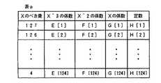
式(23)および式(24)のようなG(X)でのモジュロ計算は、毎回行うとかなり計算時間をとられることになる。従って、通常は、各Xのべき乗に対するG(X)のモジュロ値のテーブルを持つのがよい。
【0237】
テーブルには、
【0238】
この表aを用いると、任意の入力データM[m−k+1]に対して、
【0239】
このようにして、最後のシンボルが到着するまで、あるいはインタリーバに収容されるデータ領域の最大列数(本実施例では124)までのシンボルが計算されると終了し、その次のタイミングで、計算結果を他の行において計算されたものと一緒に、FEC付与モジュール10tからインタリーバモジュールにFEC冗長領域データとして送る。送る順序は、e[m]、f[m]、g[m]、h[m]の順である。
【0240】
図16においても、前述した例と同様に、最後の列にはパディングされた部分があるが、この部分については符号化のための情報に加える方法も加えない方法も実現可能である。しかし、少なくともLI表示のシンボルはFEC符号化のためのデータに加えたいので、パディング部分も(たとえall“0”のデータでも)データとして加えた方が、装置化が容易になる。もし、パディング部分を含まないようなFEC符号化を行うとすると、全くデータのない(つまり情報Mがヌルである)行が存在し得る。このような場合は、FEC付与モジュールは、e[0]=f[0]=g[0]=h[0]=0のデータをインタリーバモジュールに返す。
【0241】
(3)送信側FEC処理方法3
ここでは、図5の送信側におけるインタリーバへのデータ挿入方法に対するFEC冗長データの生成方法を示す。
【0242】
図5のようにランダムにインタリーバへの書き込みが行われる場合には、送信側FEC処理方法1のような規則的な手法を用いることはできない。そこで、送信側FEC処理方法2のようなテーブルを用いて、各シンボルに対する剰余を計算し、それを加えることによって、FEC冗長領域の値を計算する手法が用いられる。
【0243】
以下に、図5のそれぞれについて簡単にFEC冗長領域の生成方法を述べる。
【0244】
送信側FEC処理方法においては、インタリーバの左端から規則正しくデータが挿入されていたので、テーブルの内容についても、図22の表aのように規則正しく並んでいた。しかし、図5のそれぞれの実施例については、その規則性がないため、それぞれ送信側と受信側とであらかじめネゴシエーションした後に、はじめて上記のような表が書けることになる。
【0245】
図5(b)の場合には、ランダムであるのは書き込む列の順序だけであり、縦方向の書き込み方は決められているので、前述した例と同様に、図22の表aだけを用いればよいが、図5(a)の方は、書き込む列の順序だけでなく、その一列の中でのシンボルの書き込み順序が異なるため、その順序情報についての表を追加して書かなければならない。
【0246】
まず、図5(b)について説明する。ここでは、図に従いデータ領域が右端7行、FEC冗長領域が4行あることとする。左端の行から、5番目、2番目、7番目(実際はヌルでデータなし)、4番目、1番目、3番目、6番目(実際はヌル)、といったデータとなる。
【0247】
すると、送信側FEC処理方法2と同様にして、情報の多項式表現M(X)は、
【0248】
以下の処理は、送信側FEC処理方法2における式(20)〜式(28)の経過と比較して、M[*]、e[*]、f[*]、g[*]、h[*]の係数を除くとほとんど同じである。従って、図22の表aを用いて、まずM[4]に対するeの係数を式(28)の方法で、
【0249】
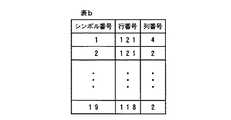
次に、図5(a)の場合を示す。この場合も図に従ってシンボル単位に書き込みが行われるとすると、図22の表a1の他に、図23の表bを用いることによって計算することができる。ここでも、図に示されているようなデータ領域が右端6行、FEC冗長領域が4行ある具体例を用いて説明する。なお、行番号は左端および上端から昇べきの順につけるものとする。
【0250】
この図23の表bに従うと、図で例えば上から4行目の情報の多項式表現M(X)は、各シンボルをM[*]で表すと、
【0251】
こうして、e[119]、f[119]、g[119]、h[119]がそれぞれ上から4行目の冗長シンボルとなる。他の行については、式(33)において情報Mのシンボル番号が異なるだけで、それ以外は同様の演算により得られる。
【0252】
以上のように、図5(a),(b)の例でのFEC冗長領域の計算は、送信側FEC処理方法2を多少変形した方法を用いることによって実行することができる。
【0253】
図7および図8のような構成以外の例として、インタリーバの一列が1セルよりも大きい場合、また、インタリーバの複数列に対してSSCSヘッダを付加する場合等が考えられるが、これらの場合においても、図13、図16、図5のそれぞれの例に合わせて、全く同様の演算でFEC冗長シンボルの計算が行える。
【0254】
これまでは3種類の例をあげて、送信側におけるFEC冗長領域の計算方法について説明してきたが、今度はそれぞれに関する受信側での復号方法および誤り訂正方法について説明する。
【0255】
送信側のインタリーバモジュール8tから出力されたデータはセルとして伝送され、受信側に到達し、セル分解の後、受信側のデインタリーバモジュール8rに入る。ある送信側インタリーバからの受信データは、データ領域の何列かをペイロードに含む1つ以上のCPCS−PDUと、FEC冗長領域の何列かをペイロードに含むやはり1つ以上のCPCS−PDUから成っている。このうち、データ領域をペイロードに含む全CPCS−PDUが、CPCSレイヤにおけるCRCチェック等によって、全てエラーなしと判定された場合、SSCSレイヤにおいては、SSCSヘッダ/トレイラを除去するのみで残りのデータをそのまま上位のアプリケーションモジュール4rに渡す。そして、そのデインタリーバに関して、FEC冗長領域をペイロードに含むCPCS−PDUは全て、デインタリーバ用のメモリに書き込むことなく廃棄して構わない。
【0256】
ただし、データ領域側データをペイロードに含む複数のCPCS−PDUにおいて、1つでもCRCチェック等によるエラーがあるときには、そのデインタリーバに関連する全てのデータは、FEC冗長領域のものを含めて、誤り訂正のために必要なものとなる。
【0257】
図7の場合は、デインタリーバの一列から1つのCPCS−PDUを構成しており、しかもそれが1つのセルとなる。このため、受信したCPCS−PDUにおいてCPCSトレイラのCRCチェック等が異常であるという場合には、該CPCS−PDU内にビット誤りが発生していることを意味している。この時、エラーの発見された列はデインタリーバモジュール8r上で、伝送中にセル廃棄された場合と同じ扱いにしてしまう。すなわち、そこの一列にはセルが到着しなかったと同等にみなす。そしてその結果として生じたセル抜けの位置をSSCSヘッダのSNチェックにより確認する。
【0258】
一方、図8のような場合は、デインタイリーバの一列は1セルであるが、CPCS−PDUは複数列にまたがって構成される。従って、CPCSトレイラによるチェックのみでは、ランダム誤りおよびセル抜けの状態が不明確である。仮にあるCPCS−PDUにおいてセル抜けがあったとすると、CPCSトレイラの機能だけでは、そのCPCS−PDUに属する他のデインタリーバ列がエラーフリーである保証がなされない。
【0259】
そこで、まずセル抜けに対しては、SSCSヘッダ/トレイラのSNを用いて確認する。SN自体に誤り検査ビットを加えておくと、抜けた位置を特定する際の確実性が増す。また、ランダムなビット誤りへの対策としては、SSCSヘッダ/トレイラがデインタリーバの1列毎についているので、この部分にSSCS−PDU全体の誤り検出機能を付加する。そして、伝送中のセル廃棄によって、CPCSトレイラの誤り検出機能が有効に働かなかった場合、あるいはビット誤りによってCPCSトレイラのCRCチェックにエラーが発見された場合に限って、SSCSレイヤにおけるデインタリーバ一列単位の該誤り検査を行い、各列のエラーの有無を検査するという方法が考えられる。これによって、CPCS−PDUのサイズによらず、実際にビット誤りおよびセル廃棄の発見されたインタリーバ列に属するシンボルのみを訂正すればよいことになる。
【0260】
また、別の場合として、デインタリーバの一列が複数セルで構成され、その一列をペイロードに含んでSSCS−PDUおよびCPCS−PDUを構成することも考えられる。ここでも、1つのセルが伝送路中に廃棄された場合には、その他の部分のシンボルエラーはCPCSトレイラを用いても検出不可能になる。この場合には、計算を簡単にするために、該当する一列全てが廃棄されたとみなして誤り訂正を試みる方法をとることができる。このような方法を用いることによって、例えば図7の例に比べて誤り訂正能力は若干落ちるが、処理遅延は増加させることなく小さく保持できる。廃棄されたとみなされるデインタリーバ一列の位置は、SSCSヘッダ/トレイラによって特定される。
【0261】
SSCSヘッダを除いたデータは、インタリーバと全く同様の順番でデインタリーバ領域に書き込む。この書き込み順は、あらかじめ送受信間でネゴシエーションされているものとする。その際、抜けのある部分については、そのことを別領域に明示するか、あるいはダミーのペイロードデータを書き込む。そして、そのデータをFEC訂正モジュール10rに渡し、シンボル抜けの部分を再生する。その後に、情報データをデインタリーバモジュール8tから書き込んだ順に読み出して、受信側のアプリケーション処理モジュール4rに送る。
【0262】
以下では、上記FEC演算の送信側FEC処理方法1,2,3に従って、受信側のFEC訂正モジュール10rにて行われる夫々の場合に対応する誤り訂正操作を、受信側FEC処理方法1,2,3として説明する。このモジュールが動作するのは、デインタリーバの任意の一行において、訂正可能な範囲のシンボルエラーがあり、かつその位置が判明している場合であり、以下では、そのような場合を例にとって説明する。なお、図7にあるように、インタリーバの一列がすべて1セルのペイロードに収容され、また該1列のみでSSCSレイヤのペイロードを構成する場合について説明するが、それ以外のデインタリーバの構成にも適用可能である。
【0263】
(4)受信側FEC処理方法1
ここでは、送信側FEC処理方法1として述べたインタリーバに対するデインタリーバを用いた誤り訂正方法を記す。
【0264】
送信側FEC処理方法1ではFEC冗長領域が4シンボル分である場合について記してあるので、この受信側FEC処理方法1でもそれに従って記述する。FEC冗長領域が4シンボルの場合、誤りシンボル位置が明確であれば、4シンボルまでの誤りを訂正することが可能である。
【0265】
いま、s番目、t番目、u番目、v番目のシンボルに誤りまたは抜けがあるとする。ただし、0<s<t<u<v<(m+1)であるとする。
【0266】
図14は、送信側FEC処理方法1において説明したように、デインタリーバのできるだけ右側につめてシンボルを挿入する構成をしている。デインタリーバ上に埋まるデータ量は毎回可変なので、受信が開始された時点では、どの位のデータが到着するかの予測ができない。従って、送信側と同様に、可変シンボル長に柔軟に対応できるような復号処理を行う必要がある。
【0267】
受信シンボル列は、情報シンボルと冗長シンボルとの合計がmシンボルあるとすると、(17)式から、
【0268】
さて、FEC訂正モジュール10rでの処理を行うまでに、既にシンボル単位にエラーの有無が明確になっている。もし1シンボルもエラーがない場合には、式(34)は、
【0269】
【0270】
すると、シンドロームS[i](i=1,2,3,4)は、以下のようにして計算される。
【0271】
手順1:S[1] =S[2] =S[3] =S[4] =0とおく。
【0272】
手順2:シンボルが1 つ来る度に(すなわちデインタリーバの1 列が到着する度に)、
【0273】
手順3:手順2を最後のシンボルまで計算した時のS[i](i=1,2,3,4)の値が、求めるシンドローム値である。
【0274】
手順2を詳細に説明する。最終的には式(37)の値を求めたいのであるが、受信を終了するまで、シンボル数がどれだけあるのかがわからない。よって、シンボルを受信する度に計算を行い、突然シンボル受信が終了したとしても、シンドロームS[i](i=1,2,3,4)の計算結果が最終的に求める値になっている必要がある。
【0275】
実際に、手順2では、以下の計算と同じことを行っている。まず、最初のシンボルC[m−1]が到着すると、シンドローム値は、
【0276】
次に、シンボルC[m−2]が到着すると、
【0277】
同様にしていくと、最終的に
【0278】
このような方法をとることによって、k個のシンボルが到着した時には、必ずシンドロームS[i](i=1,2,3,4)は、(k−1)次の多項式にα^(119+i) (i=1,2,3,4)を代入した形をとっているので、デインタリーバモジュール8rのシンボル到着がいつ終了しても、常にその時点の本実施例に基づくデインタリーバ構成での正しいシンドローム演算値を示していることになる。なお、式(40)〜(42)において、エラーのあるシンボルを受信した部分については、C[*]からE[*]に表記を書き換えるとよい。
【0279】
次に、このようにして得られるシンドローム値の意味を考える。誤りのあるシンボルがもし正しく受信されていたとすると、これらはそれぞれ、C[m−k](k=s,t,u,v)と表される。すると、これらの記号を用いて式(37)のシンドロームS[1]の値は、
【0280】
なお、本実施例では、α^bcは、αの(b×c)乗を表すものとする。例えば、上記のα^120(m−s)は、αの(120×(m−s))乗を表す。
【0281】
他のシンドロームも同様に、
【0282】
このことから、式(39)の手順によってS[i](i=1,2,3,4)の値が求められると、式(45)は、C[m−s]、C[m−t]、C[m−u]、C[m−v]に関する連立方程式となる。そしてこれを解くことによって、それぞれの正しいシンボル値が求められる。本実施例では、エラーシンボルの見落としがない(すなわち、SSCSレイヤ以下によってエラーのあるシンボルが確実に検出され、それ以外には存在しない)ことを想定しているので、これらの連立方程式には、必ず一意な解が存在する。
【0283】
解は、それぞれ、
【0284】
式(45)において、エラーシンボルがもし1つ(E[m−s])のみであれば、上式は、
【0285】
また、もしエラーシンボルが2つ(E[m−s]とE[m−t])であれば、式(45)は、
【0286】
そして、解は、
【0287】
また、エラーシンボルが3つ(E[m−s]とE[m−t]とE[m−u])であるとき、式(45)は、
【0288】
解は、
【0289】
これらの演算には、αのべき乗の計算が多数必要となる。常に出てくる演算(例えばα^120等)に関しては、表を作っておくと高速化を図ることができる。
【0290】
(5)受信側FEC処理方法2
ここでは、送信側FEC処理方法2で述べたインタリーバに対するデインタリーバを用いた誤り訂正方法を説明する。
【0291】
受信側FEC処理方法1と同様に、FEC冗長領域の大きさと同じ4シンボルまで訂正可能である。そこで、0<s<t<u<v<(m+5)であるような、s番目、t番目、u番目、v番目にそれぞれシンボル誤り、またはシンボル抜けがあるとする。
【0292】
図16の場合は、送信側FEC処理方法2で説明したように、データ領域内のシンボルはデインタリーバのできるだけ左側に詰められており、一方FEC冗長領域のシンボルは、デインタリーバの右端4列に入れられているような構成である。受信側FEC処理方法1と同様に、データが終了するまで、デインタリーバのデータ領域のどこまでデータが入るかは毎回に異なり、全くわからない。従って、シンボル受信開始と同時に復号演算を開始し、シンボル受信がいつが終了したとしても、即座に誤り訂正処理に入れるような復号処理を行う必要がある。
【0293】
受信シンボルは、受信側FEC処理方法1の場合とは異なり、データがmシンボル(0<m<125)、冗長部分が4シンボルあるとする。このとき、受信シンボル列Rは(17)式から、
【0294】
FEC訂正モジュール10rでの処理を行うまでに、既にシンボル単位にエラーの有無が明確になっている。シンボルの訂正を簡単にするために、式(53)において、E[128−s]、E[128−t]、E[128−u]、E[128−v]は全て値が0であるとおき、訂正後のシンボルをそれぞれC[128−s]、C[128−t]、C[128−u]、C[128−V]とする。
【0295】
受信側FEC処理方法1に従って、式(37)のようにシンドロームS[i](i=1,2,3,4)を定義すると、これらは以下のように計算される。
【0296】
手順1:S[i]=0(i=1,2,3,4)とおく。
【0297】
手順2:シンボルが1つ到着する度に、
【0298】
手順3:手順2で最後のシンボルまで計算した時のS[i](i=1,2,3,4)の値が求めるシンドローム値である。
【0299】
上記手順においてC[127]が到着した時点で、仮に正しいデータ領域シンボルの到着が終わったとすると、
【0300】
このようにして得られるシンドローム値は、もし受信シンボルに全く誤りがなければ全て0となる。実際は、受信側FEC処理方法1の式(45)にならって、
【0301】
これらは4次の連立方程式となり、解は、
【0302】
式(56)において、エラーシンボルがもし1つ(E[128−s])のみであれば、上式は、
【0303】
また、もしエラーシンボルが2つ(E[128−s]とE[128−t])であれば、式(45)は、
【0304】
これも2つのシンドローム、例えばS[1]とS[2]のみを計算すればよく、他のシンドロームに対してかかる分の演算を減らすことができる。
【0305】
そして解は、
【0306】
また、エラーシンボルが3つ(E[128−s]とE[128−t]とE[128−u])であるとき、式(56)は、
【0307】
解は、
【0308】
これらの演算を行う場合には、α^(119+i)(128−k) (k=1〜128),(i=1,2,3,4)の演算に多少の時間がかかってしまうので、iおよびkをパラメータとした表をあらかじめ作成しておくと、毎回αのべき乗を計算するよりもより高速に演算ができる。
【0309】
(6)受信側FEC処理方法3
ここでは、送信側FEC処理方法3で述べたインタリーバに対するデインタリーバを用いた誤り訂正方法を示す。
【0310】
受信側FEC処理方法1、2と同様にエラーシンボルは最大4つまで訂正可能である。そこで、それらのエラーシンボル位置をそれぞれs番目、t番目、u番目、s番目(0<s<t<u<v<(m+5))とする。
【0311】
図5の場合は、到着したシンボル毎にデータ領域のシンボルはランダムに、またFEC冗長領域のシンボルは、受信側FEC処理方法1、2と同様にデインタリーバの右端4列に位置する。この場合も、デインタリーバによっていつシンボル受信が終了するかわからない。よって、そのような可変シンボル長に柔軟に対応できるような復号処理を行う必要がある。
【0312】
一般的には、エラーがのった受信シンボルは式(34)で、エラーフリーの場合の受信シンボルは式(35)で夫々表されるが、以下では、図5にある具体例を用いて説明する。
【0313】
まず、図5(b)についてみると、全てのシンボルが正しく受信できたときの受信系列Cは、
【0314】
さて、式(65)のシンボルのうち、最大4つのシンボルがエラーを起こしているとする。ただし、冗長シンボルのみのエラーである場合は、誤り訂正処理を行わないので、ここでは、少なくとも1つのエラーシンボルは、データ領域に属するシンボルであるとする。
【0315】
受信側FEC処理方法1、2と同様にエラー数に応じて、シンドロームS[i]の計算を行う。エラーシンボル数と同じだけのシンドロームの計算を行えば、誤り訂正が可能である。シンドロームの計算は、
手順1:S[i]=0 (i=1,2,3,4)とおく。
【0316】
手順2:受信シンボルに応じて、以下の計算を行う。
【0317】
【0318】
手順2において、f(k)はC[k]と対になる、多項式上のべき乗数を示す。例えば図5(b)において、C[8]に相当するべき乗数はf(8)=6である。
【0319】
上記演算により得られるS[i](i=1,2,3,4)の別の表現は、式(45)の変形で与えられる。誤りのあるシンボルの訂正後の値をC[m−k](k=s,t,v,u)とすると、本実施例の具体例では、m=8なので、
【0320】
式(66)と式(67)から、4次の連立方程式ができ、これからC[8−k](k=s,t,u,v)の値を求めることができる。エラーシンボルが4つあるときの解は、それぞれ
【0321】
式(67)において、エラーシンボルがもし1つ(s番目)のみであれば、上式は、
【0322】
また、もしエラーシンボルが2つ(s番目とt番目)であれば、式(67)は、
【0323】
そして、解は、
【0324】
また、エラーシンボルが3つ(s番目とt番目とu番目)であるとき、式(67)は、
【0325】
このときの解は、
【0326】
これらの演算には、αのべき乗の計算が多数必要となる。常に出てくる演算(例えばα^120等)に関しては、表を作っておくと高速化を図ることができる。
【0327】
次に、図5(a)の場合を説明する。これは基本的に図5(b)と同じであるので、図に示した具体例のみを説明することとする。
【0328】
図5(a)の場合は、受信側でも送信側と同じ表2を持っていて、シンボル到着の度に、そのシンボルがデインタリーバのどの位置にくるのかを把握しておく必要がある。ここでも、送信側と同じく上から4行目を例にとり、この行がもし全くエラーがないとすると、受信シンボルを使った多項式は、式(32)から
【0329】
この場合も、最大4シンボルのエラーを想定する。シンドロームの計算方法は、式(66)にある手順と全く同じである。ただし、kの値は式(75)にあるC[k]から取り出されているので、ランダムな値をとる。そして、f(k)は式(75)において、そのkの値に対するC[k]を係数とするXの次数を表す。例えば、k=1に対して、f(1)=7である。
【0330】
エラーがある場合のシンドロームの値は0にはならず、式(67)にならって記述すると、
【0331】
式(66)と式(76)を解くことによって、訂正後のシンボル値が計算できる。まず、4つのエラーがある場合は、
【0332】
式(67)において、エラーシンボルがもし1つ(s番目)のみであれば、上式は、
【0333】
また、もしエラーシンボルが2つ(s番目とt番目)であれば、式(67)は
【0334】
そして、解は、
【0335】
また、エラーシンボルが3つ(s番目とt番目とu番目)であるとき、式(67)は、
【0336】
このときの解は、
【0337】
本実施例では、データの信頼性を保証するためのプロトコルとしてはAALタイプ5のSSCSレイヤのFEC処理以外を想定していない。しかしながら、実際にはFECの能力には限界があり、一定数以上セルが廃棄された場合にはもはやFECによる誤り訂正は不可能となってしまう。このような状況では再送による誤り訂正を行なうしかなく、そのためには予めSSCSレイヤのFECによる誤り訂正の他に上位レイヤにライトウェイトな再送制御を実装しなければならない。FECで訂正できない場合、元のデータを得るには再送を行なうしかないので、本実施例では、SSCSの上位にライトウェイトな再送制御のためのプロトコルは実装していると想定している。また、予めATM網の状態をみて誤りの多く発生する状態であれば能力の高いFEC用符号を用いる、またほとんど誤りの発生しない状態であれば軽いFEC符号を用いるなど、パラメータを選択した上で通信を開始できる。
【0338】
なお、前述のように、本実施例ではAALタイプ5に関するものについて説明したが、本発明の誤り訂正方法はデータ転送に限定されるものではなく、同様の方法で他のタイプにも適用可能である。
【0339】
逆に、例えば、AAL5機能のみが実装された端末装置において、該端末装置がマルチメディア/コンティニュアスメディア処理機能(音声、動画等)を持っていれば、この様なアプリケーションを実現する場合にAAL5の処理機能に本実施例の誤り制御方式を併用させることによって柔軟に対処し様々な状況で様々なデータの信頼性を保証することができるのである。
【0340】
(第2の実施例)
次に、第2の実施例を説明する。第1の実施例は、1対1の端末が通信を行なう場合の例であったが、第2の実施例では、1対多通信の場合について説明する。
【0341】
本実施例では、図24に示すように、1台の送信側端末2tが、複数台の受信側端末2r(2r−1〜2r−n)に対して通信を行なっているものとする。なお、図中の受信側端末2rのいずれか複数個が受信側端末かつ送信側端末となり、同じようなコネクションを張り同じように1対多通信を行なうことによって多対多通信を実現することもできるが、このような場合にも、本発明を適用することが可能である。
【0342】
以下、FECを付与しマルチキャストを行なう場合の例について説明する。
【0343】
図25は、本実施例の送受信端末のプロトコルスタックの一例である。基本的な構成は、第1の実施例のプロトコルスタックとほぼ同様である。図1と異なる点は、本実施例では、いずれかのレイヤにマルチキャスト機能を提供する能力のあるプロトコルが必要になることである。
【0344】
一般的に広く知られたマルチキャスト機能を提供できるプロトコルとしては、マルチキャストIPアドレスを使ったIP転送などがある。現状のシステムでは、IPマルチキャストを行なう場合に、その上位レイヤプロトコルとしてUDP(User Datagram Protcol)が用いられるのが通常である。UDPはTCP(Transmission Control Protcol)と異なり、エンド−エンドに信頼性の保証を行なわないプロトコルであるので、転送途中でパケットが廃棄されても、ビット誤り等が生じても、訂正は行なわない。しかしながら、ここで転送しようとしているアプリケーションデータはマルチメディアで放送形態をとるデジタルメディアを想定しているので、IP+UDPのようなデータの信頼性を保証しないプロトコルでは不都合である。そこで、本実施例では、MTP(Multicast Transport Protocol)やRMP(Reliable Multicast Protocol)をレイヤ4のプロトコルとした。しかし、本発明のFECを実装している場合には、信頼性の保証を上位レイヤによる再送で行なう必要性がかなり少なくなる。
【0345】
MTPは、IPでマルチキャストを行なう場合、転送途中に生じた誤りを訂正する機能を持ったプロトコルである。現在はインターネットドラフトのRFC1301に実現の方法に関する詳細が記述されている。該ドラフトの誤り訂正の方法とは、受信者による再送要求により送信者がデータを再送するという方法である。RMPは、カリフォルニア大学バークレイ校のB.Wettenらにより提案されたものであり、MTPとほぼ同様の動作及び機能を持ったプロトコルである。しかし、両者ともCSCWなどをアプリケーションとすることを前提としているので、リアルタイム性の保証は行なっていない。
【0346】
しかしながら、例で挙げたようなアプリケーションを実現するにはリアルタイム性の保持を行なう必要がある。その場合には、受信者が誤りを検出してから送信者に対して再送要求を行なっていたのでは、遅延が許容範囲を越えてしまう可能性が高い。このような場合にも、前述した第1の実施例のように、転送するデータに予め誤り訂正を行なうための冗長な符号を付与しておくことによって、上記のような問題点を解消できるのである。
【0347】
さて、IPのような上位レイヤで提供されるマルチキャストは、ATMレベルでは図25のようにスイッチ3のコピー機能などを用いて実現される。また、コネクションの張り方としては、主に以下の2通りが考えられる。
【0348】
(1)送信側端末から全ての受信側端末に対してポイント−マルチポイントのATMコネクションを張る。
【0349】
(2)送信側端末から一部の受信側端末と一部の中継サーバに対してポイント−マルチポイントのATMコネクションを張る。中継サーバよりも(マルチキャストツリー内で)下流の受信側端末と中継サーバに関しては、該中継サーバが担当する。中継サーバとは、物理的または論理的にネットワークやサブネットを接続しているような装置を指し、AALよりも上位のレイヤでコネクションを一度終端することもある。
【0350】
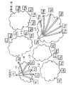
上記2の例を図26に示す。Hは送信側端末(2t)、H1〜H25は受信側端末(2r)、S1〜S5は中継サーバである。ネットワーク1−1〜1−7は、ATM網である。図26のように、送信側端末Hから受信側端末H1、H2、および中継サーバS1、S2、S3に対して、コネクションを設定し、中継サーバS1、S2、S3は、それぞれの下流に位置するATM網1−2,1−3,1−4内のマルチキャストグループに属する受信側端末やさらに下流にメンバーが存在する中継サーバに対して同じようにコネクションを張る。
【0351】
上記1の方法は,受信側端末の総数が比較的少ない場合には適切な方法である。これに対して、上記2の方法は受信側端末の総数がかなり多い場合でも、階層的に下流の中継サーバにコネクションを一度終端させることで、広域に渡るマルチキャストが実現できる方法である。
【0352】
次に、送信側端末2tおよび受信側端末2rを説明する。図27に、本実施例の送信側端末2tおよび受信側端末2rの内部構成を示す。本実施例の送信側端末2tおよび受信側端末2rの内部構成は、基本的には、第1の実施例とほぼ同様である。したがって、以下では、本実施例の送信側端末2tおよび受信側端末2rについて、第1の実施例との相違点を中心として説明する。なお、ここでも、AALとしてタイプ5を例にあげる。
【0353】
まず、送信側端末2tのアプリケーション処理モジュール104t、MTP/RMP処理を行うMTP/RMP処理モジュール130t、IP処理を行うIP処理モジュール131tでは、マルチキャストしたい送信側端末2rに対して、それぞれのプロトコルに特有な処理が行なわれる。データの種類としては、動画、音声、テキストデータなどATMの特徴を活かして様々なメディアを転送するが、ここまでの処理は、本発明に限られた方法ではない。
【0354】
次に、SSCS処理モジュール106t、CPCS処理モジュール114t、SAR処理モジュール120tでは、第1の実施例で説明したものと同様の処理が施される。
【0355】
ただし、FECを行なうSSCSレイヤで、上位レイヤに対してエラーフリーな通信を提供する場合、そのためには、SSCSレイヤ以下のレイヤでトランスペアレント(透過的)なデータの受渡しが可能であることが必要となる。というのは、送信側のSSCSレイヤのエンティティに対して、受信側のSSCSレイヤのエンティティから再送要求が送られた場合に、セル単位の再送を行なうためには、SSCSレイヤで、個々のセルの識別ができることが必須になるからである。例えば、SSCSレイヤでセル単位の再送を行なう場合、再送要求、あるいは再送に関係あるデータはSSCSレイヤよりも下のレイヤではトランスペアレントに受渡しされなければならない。これらは、受信側端末2rの処理の説明において詳しく述べる。SSCSレイヤ以下に関しても、第1の実施例と同様の処理が行なわれる。
【0356】
次に、受信側端末2rについて説明する。
【0357】
マルチキャストを行なう場合には、多くの宛先に対してメッセージを送信するため、いずれかの受信側端末2rで正しくデータを受信できない可能性が高くなる。言い換えると、送信側にいずれかの送信側端末2tから再送要求が送られる確率が高くなる。しかし、本発明によれば、予めFECを付与するレイヤ(AAL5の場合であればSSCSレイヤ)に、データの信頼性を保証する機能を持たせることで、その確率を激減させることができるのである。
【0358】
受信側端末2rでの誤り検出は、まず、CPCS処理モジュール114rで行なわれる。その際、誤りが検出されなければ、第1の実施例で示したように、SSCS処理モジュール106rを省略して上位レイヤにデータを渡す方法も可能である。その場合には、送信側で付与したFEC冗長符号のオーバーヘッド程度ですみ、スループット、レイテンシイは、AAL5にかなり近い性能を得ることができる。
【0359】
前述したように、マルチキャストの場合、IPレベルでマルチキャストグループに該当する複数のIPアドレスに対してデータグラムを送出するので、一般的なIPマルチキャストでは、送信側端末2tで再送要求を受けとる確率がポイント−ポイントの場合よりも大きい。マルチキャストグループに属する端末数が大きければ大きいほどその確率は大きくなる。例えば、受信側端末数が10^4、データリンクの誤り率が無線程度に大きい場合には、1に近い確率で送信側端末2tは再送要求を受けとる。
【0360】
誤りのレベルとしては、大きく2種類に分けられる。
(1)予め付与した誤り訂正符号(FECコード)により訂正可能な程度である場合
(2)上記1のレベルを上回り、FECコードによる訂正が不可能、よって、再送以外に訂正は無理である場合
もちろん、上記1の場合には、第1の実施例の1対1通信の場合と同様に誤り訂正を行なって、正しいデータを上位レイヤに渡すことができる。
【0361】
しかしながら、上記2のケースが発生した場合には再送により誤りを訂正しなければならず、その方法としては以下のような候補がある。
A)AALよりも上位レイヤで再送制御を行なう(例えば、図25のレイヤ4に相当するMTP/RMP等)。
B)AALのいずれかのレイヤで再送制御を行なう。
【0362】
上記Aのケースでは、それぞれの再送プロトコルの手順にしたがって誤り訂正が行なわれるので、第1の実施例で説明した手順をもちることができるが、上記Bの方法で再送制御を行なうには、第1の実施例で説明した手順に加え、いくつかの処理が必要になる。以下、上記2のようなレベルの誤りが生じ、それを上記Bのような方法で誤り回復をはかろうとした場合の手順について説明する。
【0363】
FECの訂正能力を上回るような誤りが転送中に生じた場合に、SSCSレイヤで信頼性保証のために再送制御を行なう方法について説明する。再送制御を行なうとすると、再送の単位は様々な方法が可能である。
1)ATMレイヤレベルのセル再送
2)CPCS−PDUを単位とする再送
3)SSCS−PDU(インタリーバ)を単位とする再送
4)SSCS−PDU(インタリーバ)内の列(任意の列数)を単位とする再送
5)レイヤ3以上のパケットを単位とする再送
ここでは、一例として、マルチキャストを行う場合で、かつ、上記3)のSSCS−PDU(インタリーバ)内の列(任意の列数)を単位として再送により誤り訂正を行なうケースについて述べる。
【0364】
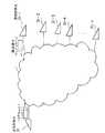
第1の実施例で述べたように、送信側端末2tのSSCS処理モジュール106tでは、セル単位にSNを含むSSCSヘッダが付与されている。受信側端末2rのSSCS処理モジュール106rでは、このSSCSヘッダに従ってセル廃棄されたセルを特定するのである。これ以前で、何らかの誤りが生じているという事実は、CPCSレイヤのCRCにより検出済みである。検出した誤りが広範囲に及んでおり、送信時に付与されたFECの訂正能力を越えている場合には、送信側のSSCSレイヤに対して、再送要求を出す。再送要求のメッセージは、マルチキャストグループのメンバーである受信側端末のいずれかから送られることが予想され、その台数はわからない。1台だけかも知れないし、または数台から送られることもある。
【0365】
例えば、受信側端末2r−1のみが訂正能力以上の誤りを検出した場合、送信側端末2tのSSCS処理モジュール106tに対して、受信側端末2r−1は少なくとも自分のアドレス、またはマルチキャストアドレス、再送して欲しいセルのSNを送ることによって誤り訂正を実現する(図28参照)。
【0366】
受信側端末2r−1が送信した再送要求は、送信側端末2tのSSCS処理モジュール106tに届けられる。送信側端末2tでは再送要求メッセージの内容に応じて、それに対応するSNを持つセルを再送する。その際、マルチキャストコネクションとは別に設定されたポイント−ポイントコネクションを利用して、再送要求を送信した受信側端末にのみ再送データを送信しても構わないし、再度マルチキャストを行なっても構わない。
【0367】
廃棄されたセルをSSCS−PDU内のどの列に対応するかということをSNから特定できても、この例ではAAL5を前提としているので、通常、その廃棄されたセルのみを転送することはできない。AAL5のトレイラが付与され、1セル分の実データでも2セル分のAAL−PDUとなってしまう。再送データを転送する方法としては、以下のようなものが可能である。
(1)実データを独立したインタリーバに格納し直して、新たにFECを付与し、独立したAAL−PDUとして送出する。この場合は、廃棄された時のSNも新たなSSCSヘッダ/トレイラに記す必要がある。
(2)AALをヌルにして送出する。SSCSヘッダ/トレイラは以前のものを付与する。
(3)再送要求を受けとった時点で、その時、またはその次に転送するインタリーバの最初または最後に含ませてしまう。他のデータと混ざらないように、再送データであることの表示が必要。
【0368】
また、上記の方法での、再送の宛先としては、以下のそれぞれがある。
A)マルチキャストグループに属する全ての受信側端末(マルチキャストによって転送する)
B)再送要求を送ってきた受信側端末のみ(何らかの方法でポイント−ポイントのコネクションを設定する必要がある)
C)再送用のコネクションを個々の受信側端末に対して予め張っておいて、再送要求を送ってきた受信側端末に対してのみ再送する。SSCSヘッダ/トレイラは以前のものを付与する。
D)マルチキャストグループ内の一部
上記1の場合には、廃棄されたセル数が小さいと、FECコードの冗長性が高くなってしまう可能性がある。
【0369】
上記2の場合には、最小限のデータ量を網に送出することになりオーバーヘッドが小さい。
【0370】
上記Aのように、マルチキャストで再送データを送出すると、特定の受信側端末だけにコネクションを張り直すという処理を送信側端末が行なわなくて済むという利点がある。
【0371】
マルチキャストデータに再送セルを含ませる場合、受信したデータが再送データであるという識別は、SSCSヘッダ/トレイラに再送データであることを示すビットを立てるようにすれば良い。すでに正しく受信できている場合には受信側のSSCS処理モジュール106rで廃棄してしまえば良いので実現は比較的簡単である。
【0372】
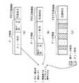
図18のSSCSヘッダ/トレイラの例にはそのようなフィールドがなく、SSCSレイヤでエラーフリーな通信を提供する場合には、図29のように拡張したSSCSヘッダ/トレイラが通常の転送時から必要になる。
【0373】
(1)は、図18では1バイトであったSSCSヘッダ/トレイラに、再送データであることを表示するフィールドを1ビット付加した。
【0374】
(2)は、バイト単位が望ましいという見地から、SSCSヘッダ/トレイラのSNをより大きな値までとれるようにし、インタリーバ内のデータ領域と冗長コードの領域がより確実に識別できるようフィールドを増やした。
【0375】
(3)は、(2)とは逆に、SNフィールドを小さくすることによって1バイトのSSCSヘッダ/トレイラ内に再送データ表示フィールドを1ビット設けた。
【0376】
再送セル数は、FECの訂正能力に依存して減らすことが可能である。例えば、FECの訂正能力が128セル中4セルだった場合、再送要求で8個のセルを再送するようにリクエストされたとする。このFECコードでは4セル以内の廃棄ならば訂正できるので、再送するセル数は少なくとも4セル送ってやれば済む。このように、最小限のセルを送ることによって、網の輻輳を引き起こさないように防止することができる。このような利点も、FECを用いている場合の特徴の一つである。
【0377】
次に、送信側端末に複数の受信側端末から再送要求が送られてきた場合について説明する。ここでは、FECの訂正能力としては、1インタリーバのサイズが16セル、その内、1セルまでの訂正が可能なコードであるものとして説明する。
【0378】
廃棄されたセルを全て再送する方法の他に、次のようにして再送セルの数を削減できる方法がある。
【0379】
図30のように、受信側端末2r−1,2r−3から各々次のようなセルの再送要求が送信側端末2tのSSCS処理モジュール106tに到着したとする。
受信側端末2r−1→セルのSN…1,2,3
受信側端末2r−3→セルのSN…2,3,4
どの受信側端末で、どのセルが廃棄されたのかが、送信側端末で上記のように特定できた場合、その後の処理として以下のような方法がある。
(1)受信側端末が受信できなかったセルのSNを全て再送する。
(2)FFCの能力に応じて復号に必要な最小限のセルを再送する
ここでもそれぞれ、マルチキャストで送る方法と、ポイント−ポイントで送る方法がある。
【0380】
上記の廃棄されたセルのSNを比較すると、2と3が共通であることがわかる。上記2の方法に従えば、それぞれの受信側端末で3セルずつ廃棄が生じているので、それぞれ、あと2セルずつ正しく受信できれば、残りの1セルはFEC符号により回復することができる。よって、前で説明したように最小限のセルを再送する、というポリシーに基づいて、送信側端末2tは、受信側端末2r−1,2r−3に対して共通の廃棄セルであるSN=2,3を送信するという方法がとれる。もちろん、受信側端末2r−1に対してSN=1,2,3のセル、受信側端末2r−3に対してSN=2,3,4のセルと、個々に最小限のセルを送ることもできる。しかし、マルチキャストグループ内の特定の端末に対して再送を行なう場合には、先にも述べたが対応するポイント−ポイントのコネクションが必要になる。
【0381】
送信先は、前述した例と同様に、受信側端末2r−1,2r−3に限ることもできるし、再度マルチキャストによってこれらの2セルのみ、またはSN=1,2,3,4,の4個のセルを送ることもできる。
【0382】
マルチキャストによる場合、すでに正しく復号されている受信側端末ではデータが再送セルであることをSSCSレイヤで検出することができるのでそのセルは廃棄することができる。よって、重複して別のデータに混入してしまって、影響を及ぼす恐れはない。
【0383】
この時の再送セルもオーバーヘッドを最小限にするために、再送セルのみをCPCS−SDUにせず、SSCSレイヤのレベルで別のインタリーバに挿入してしまうことが可能である。
【0384】
マルチキャストグループ内の特定の受信側端末(ここでは受信側端末2r−1,2r−3)にだけデータを送るようにするには、送信側端末か、もしくは送信側端末と受信側端末の中継点で特定の受信側端末にだけコネクションを設定して必要最小限のセルのみを転送するという方法が考えられる。
【0385】
以上の例では、セル廃棄を検出した受信側が再送要求を出すという、Negative ACK(否定的な応答確認)を用いた方法であったが、Positive ACK(肯定的な応答確認)を用いる方法もとることができる。
【0386】
このような場合には、送信側端末2tがマルチキャストデータを送信後、SSCS処理モジュール106tでタイマを起動して、マルチキャストグループの全ての受信側端末2rからACKが返ってくるのを待つ。ACKには、受信側端末2rのアドレス、受信できたデータの識別子などが記されている。
【0387】
タイマの上限値の設定は、ラウンドトリップタイムに応じて設定される。このタイマの上限値を越えてもACKが返ってこない場合には、その返事のない受信側端末に対してそれに応じたデータを再送する。この再送の方法は、今まで述べてきた方法と同様である。
【0388】
このデータ送出のメカニズムはTCPのウィンドウ制御によく似ている方法であり、同じようにスライディングウィンドウを用いることもできる。ただし、マルチキャストという環境下でPositive ACKを用いているので、全ての受信側端末2rからACKが返ってこないとそれに対応するデータは再送用のメモリから排除できなくなってしまう。よって、ACKが経路の途中の輻輳を起こしているノード等で送れてしまっている時には、送信者は次のデータを送出できないという状況に陥ってしまい、スループットの低下が起こる可能性もある。
【0389】
受信側のAALより上位のレイヤには、SSCSレイヤでのFECと再送による誤り制御の効果で、エラーフリーな正しいデータが渡されることになる。その後は、レイヤ3,4の通常の処理が行なわれ、アプリケーションレイヤにはもちろん正しいデータが届けられる。
【0390】
受信側の説明に含めて、再送時の送信側の説明を述べた。このように行なうことで、マルチキャストを行なっている時に、FECの能力を越えてしまうほどの誤りが転送中に生じても、最小限のオーバーヘッドと遅延でサービスを提供できる。
【0391】
上記したように送受信側端末の処理を行なうことで、AALレベルにエラーフリーな通信を提供することが可能である。マルチキャストを行なう場合は、受信側端末の数が大きければ大きいほど、いずれかの受信側端末から送信側端末に対して再送要求が生じる可能性が高い。しかし、AALレベルにFEC機能を持たせ、さらに、再送による誤り訂正を提供することによって、信頼性が高く、リアルタイム性のより保証されたシステムを構築することができる。
【0392】
以上、各実施例にて説明したように、本発明によれば、ATM通信網で高速通信を行う場合に、AALのいずれかのレイヤにインタリーバとFECを用いた誤り制御方法を実装し、さらに、インタリーバのサイズを柔軟にアプリケーションデータのサイズに合わせることによってデータ転送の高効率化、高速化、省資源化を図ることができる。特に、AALタイプ5で高速データ転送を行う場合には、CPCSよりも上位のレイヤに本発明の誤り制御方法を適用することによって、本来FECが持つオーバーヘッドを最小限に抑えつつ、AALタイプ5の高速性を最大限に発揮することが可能となる。また、AAL1、2、3/4に対しても、より高効率にFECを実装することが可能である。
【0393】
また、本発明は、上述した各実施例に限定されるものではなく、その要旨を逸脱しない範囲で、種々変形して実施することができる。
【0394】
【発明の効果】
本発明によれば、信頼性の高いデータ通信を効果的に実現することができる。
【図面の簡単な説明】
【図1】本発明の第1の実施例の送受信端末のプロトコルスタックの構造を示す図
【図2】送信側端末2tおよび受信側端末2rの内部構成を示す図
【図3】AAL−IDUとして上位から渡されるアプリケーションデータを示す図
【図4】インタリーバへのアプリケーションデータの書き込みの様子を示す図
【図5】インタリーバへの書き込み順序の例を示す図
【図6】4オクテット単位でデータ長のアライメントをとる場合の様子を示す図
【図7】インタリーバにデータを格納した様子を示す図
【図8】他のインタリーバにデータを格納した様子を示す図
【図9】図8の場合の処理の流れを説明するための図
【図10】図7および図8の場合のLIフィールドの例を示す図
【図11】インタリーバからのデータの読み出しの例を示す図
【図12】FEC冗長コードの付与の例を示す図
【図13】データ領域内の最終列の長さ表示の例を示す図
【図14】図13のFEC演算の立場から見たマトリクスの状態を示す図
【図15】マトリクスの1ラインの符号語構成の例を示す図
【図16】データ領域にダミーを入れる場合のインタリーバの状態を示す図
【図17】SSCSヘッダ/トレイラを付与する単位を示す図
【図18】SSCSヘッダ/トレイラの一例の図
【図19】インタリーバ1つに対するSSCSヘッダ/トレイラを示す図
【図20】UUI=1を含むセルが廃棄された場合の受信側でのレイヤ処理を説明するための図
【図21】図8の場合の処理の流れを説明するための図
【図22】モジュロ値のテーブルを示す図
【図23】冗長シンボルのテーブルを示す図
【図24】本発明の第2の実施例における1対多通信の形態を示す図
【図25】同実施例の送受信端末のプロトコルスタックの構造を示す図
【図26】ATMコネクションの張り方を説明するための図
【図27】送信側端末2tおよび受信側端末2rの内部構成を示す図
【図28】受信端末2r−1において再送要求が出された場合について説明するための図
【図29】SSCSヘッダ/トレイラの例を示す図
【図30】複数の端末から再送要求が送られた場合について説明するための図
【図31】ATMアダプテーションレイヤを説明するための図
【符号の説明】
1…ATM網、3…ATM交換機、2t…送信側端末、2r…受信側端末、4t…アプリケーション処理モジュール、4r…アプリケーション処理モジュール、6t…SSCS処理モジュール、6r…SSCS処理モジュール、8t…インタリーバモジュール、8r…デインタリーバモジュール、10t…FEC付与モジュール、10r…FEC訂正モジュール、12t…SSCSヘッダ/トレイラ付与モジュール、12r…SSCSヘッダ/トレイラ確認モジュール、14t…CPCS処理モジュール、14r…CPCS処理モジュール、16t…LI付与モジュール、16r…LI確認モジュール、18t…CRC付与モジュール、18r…CRC確認モジュール、20t…SAR処理モジュール(セグメンテーション)、20r…SAR処理モジュール(リアセンブリ)、22t…ATMヘッダ付与モジュール、22r…ATMヘッダ削除モジュール、1−1〜1−7…ATM網、2r−1〜2r−5…受信側端末、30…マルチキャストサーバ、104t…アプリケーション処理モジュール、104r…アプリケーション処理モジュール、130t…MTP/RMP処理モジュール、130r…MTP/RMP処理モジュール、131t…IP処理モジュール、131r…IP処理モジュール、106t…SSCS処理モジュール、106r…SSCS処理モジュール、114t…CPCS処理モジュール、114r…CPCS処理モジュール、120t…SAR処理モジュール、120r…SAR処理モジュール、122t…ATMヘッダ処理モジュール、122r…ATMヘッダ処理モジュール、H…送信側端末、H1〜H25…受信側端末、S1〜S5…中継サーバ[0001]
[Industrial application fields]
The present invention relates to a data retransmission control method and a data retransmission control system in communication using an error correction function by FEC and an error correction function by retransmission.
[0002]
[Prior art]
In order to adapt various types of information to a communication mode using ATM cells, interworking between the ATM network and the upper layer is necessary, and an AAL having the function exists between the ATM layer and the upper layer.
[0003]
FIG. 31 shows the positioning of
[0004]
To date, four types of AAL have been standardized by ITU-T etc. according to the type of information handled. Specifically, AAL1 is real-time communication such as fixed bit rate voice / image, AAL2 is variable bit rate real-time communication, AAL3 / 4 and 5 are for variable data communication (however, AAL3 and 5 are connection-oriented (CO ) For communication, AAL4 is connectionless (CL).
[0005]
Among them, in particular, since AAL3 / 4 and 5 are for data communication, the accuracy of data that even a bit error of only 1 bit is not allowed, in other words, the received data is completely the same as the transmitted data. There can be an application that requires reliability to guarantee that it is a product. In addition, it goes without saying that the reliability of the data itself becomes necessary even when a high QOS is required for real-time applications such as AAL1 and AAL2.
[0006]
However, at present, the ATM technology is limited to the standardization of primitive parts, and the error control function is not sufficiently provided by AAL. For this reason, when a user of AAL3 / 4 or AAL5 requests data communication that requires accuracy, for example, if it is AAL5, a protocol that guarantees reliability to a higher layer than a CPCS layer that is not standardized Need to be implemented. Since the specifications have been fixed below the AAL5 CPCS layer and have already been standardized, when adding a new function depending on the service, the layer must be higher than the CPCS layer.
[0007]
Examples known so far include a method of implementing a protocol based on retransmission control (for example, ITU-T's Q.SAAL protocol) in the SSCS layer (Service Specific Convergence Subscriber; service-dependent CS layer), SSCS, There is a method in which the layer is null and a transport layer protocol (for example, TCP, OSI / TP4, etc.) is mounted on the layer.
[0008]
The above methods are all methods for ensuring the reliability by retransmission.
[0009]
However, (1) applications such as large-capacity transactions that require large-capacity real-time performance (that is, retransmission control is basically not allowed) and reliability are expected to increase in the future.
[0010]
In addition, (2) a wide area of communication networks such as LAN, MAN, and WAN has been made. The wider the communication network, the more incompatible the above-mentioned latency and error control by retransmission (retransmission of information takes a lot of time).
[0011]
(3) In general, in a method of performing error control by retransmission, the unit of retransmission is a higher layer packet group (specifically, for example, a TCP packet or a
[0012]
For this reason, it is conceivable that the data communication area that is difficult to deal with only by mounting the above-described error control method based on retransmission on an ATM terminal will increase in the future. In particular, when real-time property is important, it is essential to ensure real-time property, and it is extremely difficult to deal with an error control method based on retransmission.
[0013]
Therefore, at the 1994 Spring Meeting of the Institute of Electronics, Information and Communication Engineers, the present inventors implemented a method of implementing FEC in AAL5 under the title of “B-786 ATM network error control method, FEC (Forward Error Correction) on AAL
[0014]
The reason why AAL5 is used instead of AAL3 / 4 is, for example, as follows.
[0015]
(1) While the ATM system is regarded as the next-generation communication system, AAL for data communication (specifically AAL5), which is being standardized by standardization organizations such as ITU-T and ATM Forum, is expected to The possibility of being implemented in terminals (including multimedia terminals) is extremely high.
[0016]
(2) AAL5 is intended for high throughput and low latency.
[0017]
However, it goes without saying that the above method can be implemented in AALs other than
[0018]
In this implementation, in order to perform FEC as performed in AAL1, on the transmission side, the data passed from the upper layer is once written in a matrix-like interleaver and transferred after a redundant code is assigned. There is a need. In addition, it is necessary to specify the position of the interleaver at the time of transmission of the data (cell) that should have arrived at the receiving side but has been discarded or the arrival has been delayed more than the allowable range. In AAL1, as a default process, a sequence number (SN) is assigned to a cell in the SAR layer. Therefore, this can be used even when FEC is performed as an option, and an error location is necessarily specified. Could be done. On the other hand, the process for specifying the position is not performed in AAL5. Therefore, it has been proposed to provide the SSCS layer, which is currently null, with the function of assigning the FEC redundant code and SN.
[0019]
By the way, the interleaver assumed in the conference presentation is the same as that used in AAL1, and the size in which data can be written is fixed. In AAL1, since it is known in advance that the data to be transferred is CBR (Constant Bit Rate) such as voice and is continuously passed from the upper layer at a constant rate, even a large fixed-size interleaver can be used. There was no problem. However, in data transfer, it is not known at what timing and what size data is transferred from the upper layer. Therefore, in the case of an interleaver having a fixed size, when data much smaller than the size of the interleaver is transferred, dummy data must be padded to the remaining area and dummy cells must be sent out. This is a particular problem because the dummy data increases when the remainder when the data size is divided by the interleaver size is small.
[0020]
Therefore, with such a method, the bandwidth cannot be used effectively, and extra traffic may be increased. In addition, unlike the conventional AAL1, when dummy data enters each interleaver, a display portion for indicating where the dummy data is from is required for each interleaver, so that this portion can be accurately extracted on the receiving side. This mechanism is also required.
[0021]
In addition, since the existing interleaver reads the data passed from the upper layer once after writing it into the memory, when the direction of writing and reading is vertical, the latency is written to at least one interleaver. It took only the time needed for For example, ITU-T Recommendation I.D. The size of one interleaver which is an option of AAL1 in 363 is 47 × 124 = 5828 octets in the data area, and from the start of writing data in the first column to the start of writing in the final column in this area In the meantime, transmission to the lower layer cannot be performed at all.
[0022]
As another interleaving method, recently, ITU-T, SG XIII, Working Document TD / 27 (Rev.) (13-2) -E, March, 1994 at Geneva, “Status Report on AAL1 / 2 for video transponder. As described in the above, a method of oblique interleaving (reading and writing directions intersect diagonally) has been proposed. However, even if this method is used, there is a problem that the latency is only halved as compared with the case of intersecting vertically.
[0023]
As a countermeasure against this delay, the literature presented by Matsuzaki et al. (Spring 1994 Spring National Conference of the Institute of Electronics, Information and Communication Engineers B-853; "Study of error correction method considering consistency between ATM cell and MPEG-2 system standard") In FIG. 5, an interleaver is illustrated as if data reading and writing are in the same direction, and the above-described delay itself can be improved by performing writing and reading in this manner. Although no explanation is given for the figure, generally, it is necessary to write data to the interleaver and then to read it, and the memory area for reading and writing must also be the size of the interleaver. It is. That is, this method still has a problem that it is necessary to secure a memory area having a large interleaver and a delay for reading and writing to the memory cannot be avoided.
[0024]
In addition, when the FEC redundant code is added to the data received on the receiving side, the existing method (AAL1, etc.) has a delay equivalent to or higher than that of the FEC redundant code added at the time of conventional transmission There was also a problem that it was caused by deinterleaver processing. This is because it is necessary to sequentially store all the data that arrives at the time of reception in the deinterleaver regardless of whether the data area or the FEC redundant area. In AAL1, it is possible to detect cell discard at the SN, but the function of detecting bit errors in data is limited to the FEC redundancy code. Must be decrypted by FEC. The delay required for these processes is particularly high when bit errors are extremely rare compared to cell discard and most data is correct.
[0025]
[Problems to be solved by the invention]
As described above, error correction by conventional FEC is a method that is originally suitable for CBR transmission and the like, and is based on the assumption that data to be transferred arrives continuously from an upper layer. Therefore, it is unsuitable to implement error correction by FEC as in the past in protocols that perform data transfer such as AAL3 / 4 and 5 in particular. That is, with the fixed-size interleaver adopted in AAL1, if the data to be sent is smaller than the size, the data area of the interleaver cannot be filled with the data, so dummy data is put in the remaining area. Then there was no choice but to send a dummy cell. In such a method, the bandwidth cannot be used effectively, and extra traffic is increased, which may lead to congestion. In addition, it is necessary to clarify for each interleaver where the dummy data originates and to transmit the data so that it can be understood by the receiving side. However, the conventional AAL1 interleaver has never been considered.
[0026]
In addition, in the existing method, since the writing and reading directions are different with respect to the interleaver, there is a delay in waiting for the reading from the memory while writing to the memory. This delay is approximately proportional to the size of the interleaver, and even if the diagonal interleaving method, which is said to be relatively low in delay, is used, the delay can only be halved.
[0027]
Furthermore, even in an existing method that is considered to be a solution to this problem, the memory area of the interleaver must be secured and a delay time for reading and writing to the memory is necessary. It was.
[0028]
In addition, in the existing method performed by AAL1 or the like, there is a problem that a delay equal to or more than that in the conventional transmission occurs at the time of reception for error detection and decoding. This is because at the time of reception, not only data in the data area but also data in the FEC redundant area are all stored sequentially in the deinterleaver, and errors are detected and further corrected by FEC.
[0029]
An object of the present invention is to provide a data retransmission control method and a data retransmission control system in communication using an error correction function by FEC and an error correction function by retransmission.
[0030]
[Means for Solving the Problems]
The present invention is a data retransmission control method in communication using an error correction function based on FEC and an error correction function based on retransmission, and cannot be corrected at the transmission terminal from the reception terminal by the error correction function based on FEC at the reception terminal. A first procedure for receiving a retransmission request for requesting retransmission of erroneous communication data received with an error; an error in the error correction function by the retransmission request received in the first procedure and FEC; A second procedure for determining a minimum amount of retransmission data necessary for recovering the erroneous communication data by using the error correction function based on the FEC and the error correction function based on the retransmission based on a correction capability; , Retransmitting the minimum amount of retransmission data determined in the second procedure from the transmitting terminal to the receiving terminal. And having a step.
Preferably, the communication is multicast communication from the transmitting terminal to a plurality of receiving terminals. In the first procedure, the transmitting terminal receives the retransmission request from at least one receiving terminal, and the third procedure In the procedure, the minimum amount of retransmission data may be retransmitted from the transmitting terminal to the at least one receiving terminal.
The present invention also relates to a data retransmission control system in communication using an error correction function based on FEC and an error correction function based on retransmission. In the transmission terminal, depending on the error correction function based on FEC at the reception terminal from the reception terminal. First means for receiving a retransmission request for requesting retransmission of erroneous communication data received with an error that cannot be corrected, and the error correction function based on the retransmission request received by the first means and FEC And determining a minimum amount of retransmission data required to recover the erroneous communication data by using the error correction function by the FEC and the error correction function by the retransmission. Means and the minimum amount of retransmission data determined by the second means are retransmitted from the transmitting terminal to the receiving terminal. And having a third means for.
Preferably, the communication is multicast communication from the transmitting terminal to a plurality of receiving terminals. In the first means, the transmitting terminal receives the retransmission request from at least one receiving terminal, and the third means The means may retransmit the minimum amount of retransmission data from the transmitting terminal to the at least one receiving terminal.
[0034]
[Action]
In the present invention, the transmitting terminal receives a retransmission request from the receiving terminal for requesting retransmission of erroneous communication data received with an error that cannot be corrected by the FEC error correction function. Necessary to recover the erroneous communication data by using the error correction function by FEC and the error correction function by retransmission based on the error correction capability of the error correction function by FEC and the error correction function by FEC The minimum amount of retransmission data is determined, and the determined minimum amount of retransmission data is retransmitted from the transmitting terminal to the receiving terminal. Thereby, highly reliable data communication can be effectively realized.
[0043]
(4) Further, according to the present invention, the data portion and the redundant portion of the interleaver can be made independent. As a result, when the error rate on the network is relatively small, it is determined that there is no error in the data part of most interleavers, so FEC processing is not required, and therefore the processing time in the SSCS layer is further reduced. Can do.
[0048]
【Example】
Embodiments of the present invention will be described below with reference to the drawings.
[0049]
In this embodiment, a case is shown in which data communication using
[0050]
For example, large-capacity transaction processing is performed between the transmitting and receiving terminals, and data exchange between the two terminals is performed with low latency (retransmission control is basically not permitted), high throughput, and reliable data communication. The case where it is required is assumed. For example, a case where the terminal is connected to the WAN via a public network and is physically far away is also included.
[0051]
Here, an error correction bit for FEC (Forward Error Correction) is added to data exchanged between both terminals, and when a cell is discarded in a transmission path or ATM switch during transmission, the data is not retransmitted. A method that can reproduce correct data is shown.
[0052]
In this embodiment, the description is made mainly assuming only cell discard, which is a feature of ATM, but bit errors may occur in actual data communication. As a correction method for this bit error, a CRC field is provided in an SSCS header / trailer as described later, and a cell in which an error is detected is discarded by performing bit error detection for each cell, and the cell is regarded as being discarded. There is a way. There is also a method of using a Reed-Solomon code (RS code) that can be corrected without knowing at which position in the interleaver a bit error has occurred as a code for error correction. However, in order to apply this function, it is necessary to always perform a decoding operation for specifying an error position on the receiving side.
[0053]
In this embodiment, the transmission side terminal and the reception side terminal are ATM terminals, respectively, and use AAL5. The FEC function is implemented in the SSCS layer, which is the upper layer of the AAL5 CPCS layer, so that error-free data can be transmitted and received with high throughput and low latency.
[0054]
(First embodiment)
First, the first embodiment will be described. This embodiment is an example when a one-to-one terminal performs communication.
[0055]
FIG. 1 shows the structure of the protocol stack of the transmission / reception terminal of this embodiment. This is a protocol stack for U-plane communication (communication between applications). In the figure, 1 indicates an ATM network, and 3 indicates an ATM switch.
[0056]
Both the
[0057]
If there is at least one router between the connection between the
[0058]
The AAL5, which has already been standardized, is implemented in the AAL layer, and the interleaver processing and FEC processing of the present invention are implemented in the SSCS layer above the standard AAL5. Thereby, reliable communication is realized between end-to-end.
[0059]
However, in order to further increase the reliability, a light-weight retransmission control protocol may be implemented in the
[0060]
FIG. 2 shows an internal configuration of the
[0061]
The
[0062]
The application processing module 4t performs processing for passing application data to the
[0063]
The
[0064]
The CPCS processing module 14t performs trailer assigning work including AAL5 CPCS processing on the data received from the
[0065]
The SAR processing module 20t performs segmentation on the data passed from the CPCS processing module 14t as a normal AAL5 SAR layer process.
[0066]
The segmented data is transferred to the ATM header adding module 22t, to which an ATM cell header is added, and further, lower layer processing (not shown) is performed and the cells are input to the
[0067]
On the other hand, the receiving
[0068]
The SAR processing module 20r performs AAL5 reassembly processing on the received data (cell payload) while referring to the information at the end of the CS-PDU.
[0069]
The CPCS processing module 14r performs AAL5 CPCS layer processing on the CS-PDU received from the SAR processing module 20r, that is, checks the CRC and length display, and reproduces the CS-SDU.
[0070]
The SSCS header / trailer confirmation module 12r deletes the SSCS header / trailer attached to the CS-SDU while confirming it, and passes it to the deinterleaver module 8r. At this time, if an error is detected in the CPCS trailer, the fact is notified to the FEC correction module 10r.
[0071]
Data correctly reproduced by the deinterleaver 8r is transferred from the SSCS processing module 6r to the application processing module 4r as application data.
[0072]
By the way, the individual modules described above may be performed by either hardware processing or software processing. For example, the application processing modules 4t and 4r and the
[0073]
Next, processing in the
[0074]
(A) Processing by the application processing module 4t
First, the
[0075]
The application processing module 4t passes application data (AAL-IDU) to the interleaver module 8t. When one application data is completed, the application processing module 4t notifies the interleaver module 8t as a delimiter.
[0076]
(B) Processing by the interleaver module 8t
The interleaver module 8t sequentially writes the AAL-IDU, which is application data passed from the application processing module 4t, into the data area portion of the interleaver, which is a matrix memory. For example, writing is performed one column at a time in the vertical direction from the upper left end as shown in FIG.
[0077]
As a method of writing to the interleaver, an example according to the direction and order shown in FIG. 4 is given here, but various writing orders and directions such as the method shown in FIG. 5 are possible.
[0078]
Data is not written in the FEC redundant area, and a result obtained by performing a predetermined calculation for each symbol in each line after the writing is completed is written in each line in the corresponding FEC redundant area. It is also possible to store the result of the operation in a logically different memory without being specifically written in the interleaver area in the memory, and read it out to a lower layer as needed.
[0079]
Various interleaver sizes are conceivable. For example, in AAL1, an interleaver having the following size is an option as an ITU-T recommendation I.D. 363. As for the horizontal (column) size, one symbol is one octet, the data area is 124 symbols, and the FEC redundant area is 4 symbols. The vertical (row) size in this case is 47 octets, which is the length obtained by subtracting the SAR header length from the cell length. As other values of options in AAL1, those having the same symbol size, the vertical size of 8 symbols, the horizontal size of data 88 symbols, and the FEC
[0080]
In the present embodiment, several interleaver size values are presented, all of which indicate maximum values that the interleaver can take as a data area. That is, it can be changed smaller than that depending on the size of the application data. Even when the application data size is up to the maximum value of the side of the interleaver, if it does not enter that area, the second interleaver and the third interleaver are used, as in CAL transfer with AAL1. The data is transferred using a plurality of interleavers. In addition, there are several vertical sizes suitable for implementation in relation to the size of the cell payload.
[0081]
For example, it is assumed that one SSCS header / trailer and an AAL5 CPCS trailer are added to one interleaver column. In this case, the vertical length is equal to the SSCS header / trailer portion (one octet is considered to minimize the overhead due to the header / trailer portion) and the CPCS trailer portion (8 octets) from the payload length of the cell. Excluded length (48-1-8 =) 39 octets, etc. can be considered. Further, if one column is composed of a plurality of cells, for example, two cells, the vertical size (39 + 48 =) 87 octets is considered appropriate.
[0082]
Compare the case where the vertical size is large and the case where it is small. Compared to the SSCS-PDU having the same interleaver sequence in the payload as described above, if the SSCS header / trailer length is the same, the larger vertical size increases the transfer efficiency (packing efficiency) of the upper layer data. There are advantages. On the other hand, if the vertical size is long, there is a high possibility that the data to be transferred will end in the middle of the column. In this case, the remaining part of the column must be filled with padding, and conversely the transfer efficiency is high. There is also the problem of going down. In order to select an appropriate value for the vertical size, such a trade-off should be taken into account. Furthermore, if it is too large, there arises a problem that random bit errors are easily included or a problem that the overhead of the FEC code increases.
[0083]
With regard to the horizontal size, assuming that a Reed-Solomon code (hereinafter referred to as an RS code) with 1 symbol being n bits is used as the same error correction code as in the prior art, the maximum length is usually limited to (2 ^ n) -1 symbols. The When an extended RS code is used, one longer than that by 1 or 2 symbols can be used. However, an extended RS code is more complicated in decoding processing and error correction processing after reception than in an ordinary RS code. Therefore, in this embodiment, the extended RS code is not used. The value of n is generally 8 or a multiple thereof in consideration of the ease of processing by software.
[0084]
As shown in an example in FIG. 6, there is a method in which the horizontal size is a multiple of 4 octets as the size of the interleaver within a range not exceeding the above value. This method means that the product of n and the number of column symbols is a multiple of 32, for example, when one symbol is n bits in the RS code. Assuming that the FEC function is realized by software processing, the computer virtually writes and reads data to and from the interleaver, but the computer CPU is easier to handle when the memory access is in units of 4 octets. Therefore, when there is not enough valid data, it may be better to take alignment even if padding is performed so that it becomes a unit of 4 octets.
[0085]
As will be described in detail later, consider an example in which one CPCS trailer is added to each of the data area and the FEC redundant area. In this case, it is sufficient to consider only the SSCS header / trailer length for the length of the interleaver. Therefore, assuming that the SSCS layer overhead is, for example, 1 octet, (48-1 =) 47 bytes is considered good. However, this method does not consider that an increase of 8 octets increased by the CPCS trailer must be transmitted as the payload of the cell, so a method of securing 8 bytes for that purpose in the data area of the interleaver, Alternatively, it is necessary to take one of the methods of leaving the function of aligning the CPCS layer. In the case of leaving it to the function of aligning the CPCS layer, since only the CPCS trailer is stored in one cell, 40 bytes of padding is required, and there is a problem that the overhead increases. Therefore, packing efficiency is better when a space of 8 octets is reserved in advance for the CPCS layer in the data area of the interleaver.
[0086]
As described above, in the case of data transfer, the size of the AAL-IDU is not constant, and the
[0087]
Next, the final state in which an AAL-IDU of an arbitrary size is stored in the interleaver based on the various examples described so far will be described with reference to some examples. In these examples, it is assumed that the maximum size of the interleaver used for each connection, the size of the FEC area, the size and format of the SSCS-PDU, etc. are negotiated at the time of call setup.
[0088]
FIG. 7 shows an example in which the vertical size of the interleaver is 39 octets. This size is an example in which one octet of SSCS header / trailer (having a header as shown in FIG. 7B) and one CPCS trailer are attached to each column. The maximum number of columns in the interleaver is 128 octets, and there is a 4-octet FEC area in each row.
[0089]
Further, this example shows a state in which application data having a relatively large size is stored, and is spread over a plurality of interleavers (from # 1 to #N). Of course, even small-size application data can be stored in the same manner as the interleaver state shown in
[0090]
Next, FIG. 8 shows an example where the vertical size of the interleaver is 47 bytes. FIG. 9 is a diagram for explaining the process flow of the SSCS layer in this case.
[0091]
When AAL-IDU arrives (step S11), writing to the interleaver is performed (step S13).
[0092]
When the interleaver is satisfied (step S14), a PAD is inserted as necessary and LI is written (step S15). Then, the FEC redundancy code is calculated (step S16).
[0093]
From the interleaver, the data for each column is sequentially read and an SSCS header is added (step S17).
[0094]
Then, CPCS processing (step S18) and SAR processing (step S19) are performed, an ATM header is added (step S18), and the ATM network is transferred as an ATM cell.
[0095]
FIG. 8 shows an example in which one CPCS trailer is assigned to each of the data area and the FEC area of the interleaver. As in the example of FIG. 7, a 1-byte SSCS header / trailer is attached to each column (FIG. 8B). This example also shows a state in which application data of a relatively large size is stored, and is spread over a plurality of interleavers (# 1 to #N). Of course, even small-size application data can be stored in the same manner as the interleaver state shown in FIG.
[0096]
# 1 in FIG. 8A is an interleaver in which the data area is used up to the maximum value, and the padding amount included in the column is displayed in the LI field (1 octet) using the last 9 bytes. The rest (8 octets) is unused. This is an area for preliminarily securing the size of the trailer so that extra padding is not required when the 8-octet CPCS trailer is provided. In addition, #N in FIG. 8A is an interleaver in which an unused portion remains in the data area (application data is terminated halfway), and the final column may include padding. Similarly in this interleaver, the last 1 byte of the last column is used to display the padding amount of that column in the LI field. Therefore, if the sum of the effective data length of the last column and one octet of the LI field is less than 47 octets, the pad is added by the shortage.
[0097]
Next, the LI display method used in FIGS. 7 and 8 will be described in detail. An example is shown in FIG. (A) corresponds to FIG. 7 and represents a case where the application data ends at the bottom row of the middle column in the data area. In this case, since no valid data is included in the last column, the LI field becomes 0 and padding of 38 octets is performed. Further, FIG. 8B shows a display method in the case corresponding to FIG. 8 in the case where the end line after writing application data is the 38th to 47th octets. At this time, the LI field indicates the amount of padding. By adopting such a method, it becomes possible to accurately convey the amount of application data from the transmission side to the reception side.
[0098]
For the same application data, a plurality of AAL-IDUs can be stored in one interleaver. Therefore, after detecting the delimiter of one AAL-IDU, the timer can be started and the transmission of the interleaver can be waited until the next AAL-IDU arrives for a certain period of time.
[0099]
Various timer settings can be made depending on how much latency is required by the application. For example, it is possible to wait several seconds for file transfer etc. where the requirements for delay are not strict, and conversely, in the case of moving images etc., the timer threshold is set to 0 and the bandwidth is used to the maximum You can also
[0100]
After the application data is written in the data area, it is desirable to calculate the FEC redundant area as soon as possible in order to reduce the latency.
[0101]
As shown in FIG. 11, reading from the interleaver is performed in the same direction and order of writing, and one symbol is read immediately after the completion of writing one symbol. By performing writing and reading alternately or in parallel, the bottleneck that reading has not been possible until the end of writing has been solved, and the time taken to pass from the upper layer of the SSCS layer to the lower layer is greatly reduced. After the data is read, the data is sequentially transferred to the SSCS header /
[0102]
When performed as described above, the delay caused by the interleaving can be almost ignored, and a speed very close to that when the SSCS layer is null can be obtained. In the previous interleaving, writing was performed in the horizontal direction, and reading was performed in the vertical direction. After data was written in one data area (when everything was not filled, PAD was performed). . On the other hand, in the method of the present embodiment, the reading direction of the data to be passed to the lower layer is made the same as the writing direction, and particularly the data area is written and read almost simultaneously, so the data is transmitted until the entire data area is written. The delay is considerably reduced.
[0103]
(C) Processing by FEC grant module 10t
As shown in FIG. 12, the FEC adding module 10t calculates each FEC redundant area for each row of data written in the range of the data area and writes it in the corresponding position. The FEC redundant area for the n-th row is a result obtained by calculating using m symbols of n rows and 1 column, n rows and 2 columns,..., n rows and m columns.
[0104]
In the case of an interleaver that has not been padded, as shown in FIG. 12 (a), and in the case where data ends in the middle of the interleaver, it corresponds to each row except for unused portions as shown in FIG. 12 (b). The FEC redundant area is calculated. In the case of (b), in order to calculate the FEC redundant area for the nth row, the FEC redundant area is calculated by using the symbols from the nth row and the first column to the nth row and the fourth column by the same calculation method as when there is no unused portion Can be calculated.
[0105]
FIG. 13 shows an example in which one column is one CPCS-SDU. When the data that is AAL-IDU is written, the interleaver fills the rest of the column with PAD (for example, the bit in the symbol is all “0” or all “1”) as shown in FIG. In addition, the length of valid data included in the column is written in the last one symbol portion of the column. If the data is filled up to the end of a certain column, the length is displayed using the next column as shown in FIG. In short, the column preceding the column containing the length indication at the end of the column is filled with data.
[0106]
PAD or the like is not performed for the remaining columns where no data is written. Since the receiver side can recognize the end of the data area by the SSCS header / trailer provided in the next step, it is not necessary to perform extra PAD to match the maximum size of the interleaver. Further, a portion where data is not written is not transferred as a cell. When such an operation is performed, an interleaver suitable for CBR transfer can be easily applied to data transfer.
[0107]
When calculating the FEC redundant area, there is no parameter to be substituted for the FEC redundant code calculation in each column of the data area in which no data is written and no dummy is entered, so that the number of calculations can be reduced. However, in the conventional case where 0 or 1 is padded as a dummy and it is used as data for FEC calculation, the same calculation as that of the column with the data is performed for each symbol using the value. Since this has to be done, the same computation time is required as when the data area is filled with valid data. Therefore, if the PAD is not inserted in the remaining data area and the area is removed from the calculation area for FEC, the calculation amount is reduced, and FEC redundancy can be calculated easily in a short time. Protocol processing is possible.
[0108]
FIG. 13 shows a state in which a virtual interleave matrix is virtually written from the viewpoint of writing data and is written from the upper left, but from the standpoint of calculating redundancy for FEC, it is actually a figure. It is equivalent to being written as 14. That is, the left side of the matrix (that is, the upper part of the information part for FEC) is provided with a dummy PAD, and the actual data is placed at the right end of the data area. In the actual data area, the data with the smaller number (that is, the data coming from the upper layer earlier) is on the left side. That is, from the viewpoint of a code word that performs FEC calculation, it seems that there are an information part for lower real data and an FEC redundant part. This situation is shown in FIG.
[0109]
In addition, for example, as shown in FIG. 16, there is a method in which dummy data is inserted in a column that does not contain any data to calculate the FEC redundant area, but a dummy cell including them is not transmitted. The amount of data transmitted to the network can be minimized as in the case of FIG.
[0110]
In addition to this, the symbols are randomly arranged in the interleaved data area as shown in FIG. 5A, or the row order is freely set in the data area as shown in FIG. 5B. It is also possible to do. In these cases, similarly, by not sending the dummy data string placed in a string that does not contain any data, the amount of data transmitted from the network can be kept to a minimum as in FIGS.
[0111]
In these examples, it goes without saying that the method of inserting into the interleaved matrix is negotiated in advance before transmission in both transmission and reception.
[0112]
16 and 5 differ from FIG. 13 in that the interleave matrix structure from the viewpoint of the FEC calculation is the same as each figure. That is, in the case of FIG. 16, each codeword includes an information part and FEC in which information of actual data is above and dummy (symbol value 0) information is below, as shown in FIG. It consists of redundant parts. Further, when the real data string is randomly arranged as shown in FIG. 5B, the information part in which the real data and the dummy data are mottled as shown in FIG. 15C and the redundant part on the right side thereof. Consists of.
[0113]
In FIGS. 13, 16, and 5, the actual data portion is transmitted as a cell, but the dummy portion is not transmitted. On the receiving side, decoding is performed assuming that 0 is transmitted to the dummy part.
[0114]
The method for creating the FEC redundant area with respect to FIGS. 13 and 16 will be described later in more detail. The following protocol processing flow will be described on the assumption that the writing method to the interleave matrix of FIG. 13 is a representative example.
[0115]
When the calculation of the FEC redundant area is started, the data once written in the data area is almost transferred to the SSCS header /
[0116]
(D) Processing by SSCS header /
The SSCS header /
[0117]
The SSCS header / trailer assigned here must include information for reliably specifying the position (numbered column) of the interleaver in which the data string to which the SSCS header / trailer is attached is included.
[0118]
As a typical error correction code for performing FEC, there is a Reed-Solomon code. As a precondition for easy correction using this error correction code, there is a condition that "error position is specified". . If the error position is not specified, a large amount of calculation is required for specifying the position, and the correction ability can correct only about half of the symbol errors at the time of position specification. In order to specify an error position (here, corresponding to a position in the interleaver of a cell including data in which an error has occurred), an identifier for each cell needs to be attached in some form. The most effective method as the identifier is to give SN to each cell, for example. In addition, the SN needs to have a certain level of reliability.
[0119]
As the SSCS header / trailer, for example, a field as shown in FIG. 18 can be provided. Here, an example of a header having a length of 1 byte is shown.
[0120]
As an example of the horizontal size of the interleaver, for software processing using a CPU, it has been described above that it is desirable to align the data length to 4 bytes as a unit accessed by the CPU. However, the header / trailer length may be 4 bytes.
[0121]
Here, an example of the SSCS header of FIG. 18 will be described.
[0122]
(A) is a synchronization bit, which indicates the SSCS header / trailer at the head of the interleaver. For example, “1” is displayed at the beginning, and “0” is displayed otherwise.
[0123]
(B) is a sequence number and displays the order in the interleaver. For example, a dropout when a cell is discarded can be detected.
[0124]
(C) is a SNP (Sequence Number Protection) bit, that is, a parity bit for protecting the sequence number, and detects an error in the sequence number.
[0125]
(D) is a D / F (Data / Flag) bit and indicates whether the content of the payload is data or an FEC redundancy code.
[0126]
(E) is a B / E (Begin / End) bit, which indicates the end of each of the data and the FEC redundant code area. For example, in the interleaver, this flag of the SSCS header / trailer at the end of the data area and the FEC redundant area is set to “1”, and the others are set to “0”.
[0127]
From the interleaver, the FEC redundant area is read following the data area, and passed to the SSCS header /
[0128]
FIG. 19 shows an example of an SSCS header / trailer for one interleaver. The value shown here is an example of a correct SSCS header / trailer without error.
[0129]
The synchronization bit indicates the SSCS-PDU at the head of the interleaver, and the sequence number is circulated in 4 bits in this case. In the example of FIG. 19, the sequence number starts with the first SSCS header / trailer attached to the data area as 0 and increases modulo 16, and the last SSCS header / trailer and FEC redundancy area in the data area The first SSCS header / trailer is continuous. As another method, it can be realized even when the sequence number is cleared at the first SSCS header / trailer in the FEC redundant area and is restarted from 0. However, if the sequence number is not cleared halfway and is continuous as in the example of FIG. 19, it is easier to detect cell discard even when cell discard occurs at the boundary between the data area and the FEC redundant area. There are advantages. In addition, in the case where the size of one AAL-IDU is quite large and stored over a plurality of interleaves, a method of assigning continuous sequence numbers between consecutive interleaves, and the SSCS header at the beginning of the data area / Trailers can be considered in two ways: 0 always. The number of columns in the data area is not a fixed length, but the display of another field (D / F bit and B / E) of the SSCS header / trailer and the size of the FEC redundant area are negotiated between the end ends in advance. It is possible to correctly identify the boundary where the data area and the FEC redundant area are transferred alternately.
[0130]
In the sequence number protection, an even parity is calculated for a 4-bit sequence number. Of course, odd parity may be used instead.
[0131]
In this embodiment, if the D / F bit is 1, it indicates a data area in the interleaver, and if it is 0, it indicates an FEC redundant area. The B / E bit sets END to 1, and marks the last PDU of the SSCS-PDU in the data area and the last PDU of the SSCS-PDU in the FEC area.
[0132]
In the SSCS header / trailer shown in FIG. 19, the header / trailer having the values of B / E field = 1 and D / F field = data indicates the effective data length included in the last column of the data area of the interleaver. It is given to the SSCS-SDU including the LI field to be indicated.
[0133]
(E) Processing of CPCS processing module 14t
The normal AAL5 processing is performed on the data sequentially passed to the CPCS processing module 14t, and a length display and a CPCS trailer are attached. As an example of a unit serving as a CPCS-SDU, two types of FIG. 7 and FIG. 8 are given. In FIG. 7, an SSCS header / trailer and its payload are a unit, which is a CPCS-SDU unit. In FIG. 8, each of the interleaver data area and the interleaver FEC redundant area (two in total) is a unit of CPCS-SDU.
[0134]
In the case of FIG. 7, an SSCS header / trailer is assigned to each interleaver column, and an AAL5 CPCS trailer is assigned to each. In this method, AAL5 CRC is applied to a row of interleavers. If an error is detected on the receiving side, it is recognized that there is an error in a specific row of the interleaver. Further, even if cell discard occurs, it is possible to grasp which interleave sequence has not arrived at the receiving side from the missing sequence number in the SSCS header / trailer. In this way, it is possible to accurately specify the position of cell discard or bit error.
[0135]
As an application of FIG. 7, there is a method in which an SSCS header / trailer is added to a plurality of columns instead of one column of an interleaver. In FIG. 7, the interleaver is designed so that the sum of the overhead of the SSCS layer, the sequence of interleaver data, and the CPCS trailer is, for example, 48 octets, so that extra padding is prevented for each layer. Even when this is applied, the length of the interleaver is devised so that the sum of the length of the SSCS-PDU and the length of the CPCS trailer is a multiple of 48 octets, or the operation of the terminal that performs the communication is not effective. Even if possible, a design that minimizes padding at the CPCS layer is desirable in terms of increasing data transfer efficiency.
[0136]
In the case of FIG. 8, only two AAL5 trailers are assigned to one interleaver. Two means that one CPCS trailer is assigned to the entire data area and another CPCS trailer is assigned to the entire FEC redundant area. As for the former, since the last 8 bytes of the data area of the interleaver are unused in the interleaver module 8t in advance to minimize padding, if the CPCS trailer is added to the data passed from the SSCS layer, This is a multiple of 48 bytes, and no padding is required when performing SAR processing. On the other hand, when a CPCS trailer is assigned to an FEC redundant area, an unused portion cannot be secured in advance by the interleaver module 8t. Therefore, when a row of interleavers has a length of 47 octets as shown in FIG. Requires 40 octets of padding. However, for example, compared to FIG. 7, the overhead can be reduced by the small number of trailers of AAL5, and the transfer efficiency is increased. Further, when it is desired to reduce the padding, for example, in FIG. 8, the length of the interleaver is changed, and the remainder obtained by dividing the sum of the lengths of the SSCS-PDU including the FEC redundant area and the CPCS trailer by 48 octets is 0. It is also possible to have a value sufficiently close to 48 octets. Details will be described in the description of the SSCS header / trailer confirmation module 12r on the receiving side.
[0137]
(F) Processing by SAR processing module 20t
In the SAR processing module 20t, segmentation processing of data (CPCS-PDU) received from the CPCS processing module 14t is performed. However, if the sum of the interleaver vertical size, SSCS header / trailer size, and CPCS trailer size is 48 octets, segmentation is not performed. On the other hand, for example, when the CPCS-PDU is as shown in FIG. 8 and one CPCS trailer is provided for each of the data area and the FEC redundant area, segmentation is performed.
[0138]
The SAR-PDU divided into 48 octets is passed to the ATM header adding module 22t. At this time, if the SAR-PDU passed to the ATM header adding module 22t is data corresponding to the last part of the CS-PDU, the ATM header adding module 22t is notified of this fact.
[0139]
(G) Processing by the ATM header adding module 22t
The ATM header attaching module 22t sends an ATM cell data to the
[0140]
The above is the flow of processing in the
[0141]
Next, processing in the receiving
[0142]
(H) Processing by ATM header deletion module 22r
When the ATM header deletion module 22r receives a cell having an ATM cell header determined at the time of call setup after performing physical layer processing on the cell stream received from the
[0143]
When a cell including a bit indicating that it is a cell constituting the last part of the CPCS-PDU is discarded, as shown in FIG. 20, the same CPCS-PDU as the next arriving CPCS-PDU is passed to the upper layer. End up. However, this error is detected by checking the CPCS trailer. Further, by passing the CPCS-PDU including the error to the
[0144]
(I) Processing by the SAR processing module 20r
In the SAR processing module 20r, the data (SAR-PDU) passed from the ATM cell header deletion module 22r is assembled by referring to the indication that it is the last part of the CPCS-PDU. After completion of the assembly, the data is passed to the CPCS processing module 14r.
[0145]
(J) Processing by CPCS processing module 14r
The CPCS processing module 14r sequentially performs CRC calculation processing, which is AAL5 processing, and confirmation of the length display on the CPCS-PDU received from the SAR processing module 20r.
[0146]
Here, the SSCS processing module 6r is notified of whether or not an error has been detected in any of the CRC calculation processing and the length display value. In this case, it is not always necessary to notify which operation caused the error.
[0147]
(K) Processing by SSCS header / trailer confirmation module 12r
The SSCS header / trailer confirmation module 12r mainly removes the header / trailer while confirming that there is no omission in the SN or that a notification is received when an error is detected in the CPCS trailer.
[0148]
When it is notified that an error is detected in the CPCS trailer, it is highly possible that any of the SSCS-PDUs included in the CPCS-PDU is discarded. The position must be specified.
[0149]
Various situations are conceivable as errors in SSCS header / trailer (including bit errors). Here, how to deal with an error in the header / trailer having the field shown in the example of FIG. 18 will be described.
[0150]
The synchronization bit (a) is a bit indicating the head of the interleaver. If the SSCS-PDU includes the head data of the interleaver, the bit is set to 1; otherwise, it is set to 0. If an error occurs that inverts this synchronization bit, it may not be known from the SSCS-PDU that it is a new interleaver. However, by indicating that the previous SSCS-PDU (d) FEC redundancy code and (e) the B / E bit are the last, a new interleaver is used even if the sync bit is inverted. It is possible to detect the head of.
[0151]
When a bit error occurs in the sequence number of (b), error detection can be performed using the subsequent sequence number protection (for example, even parity) of (c). If it is found that the sequence numbers before and after are correct, after removing the header / trailer, the payload part of the SSCS can be written in the corresponding position of the interleaver. Alternatively, suspicious data can be discarded and regarded as cell discard, and correct data can be reproduced using the FEC redundancy code.
[0152]
The D / F in (d) indicates the type of payload, such as 1 if the bit string included in the payload portion is data and 0 if it is an FEC redundancy code. Further, B / E in (e) indicates that the SSCS-PDU is the last among a plurality of consecutive SSCS-PDUs including data. Similarly, the FEC redundant part indicates the last in the continuous SSCS-PDU. Therefore, when the B / E bit is 1 (in short, the SSCS-PDU is the last data), it is assumed that this indication has caused a bit error. However, since the D / F bit of the next SSCS header / trailer is changed from 1 to 0 and the payload is informed that the FEC redundancy code is included, the SSCS confirmation module 12r can recognize it correctly.
[0153]
In the above, since it is assumed that the bit error rate is a minute network such as 10 ^ (− 10) or less in the transmission path, the SSCS header / trailer and the SSCS header / trailer before and after the SSCS header / trailer are used. At the same time, description is made on the assumption that there is no bit error of 2 bits or more (where ^ means power). In practice, however, the range may contain an error of 2 bits or more, in which case, for example, the size of the FEC redundant area of the interleaver is fixed, It is possible to reproduce an accurate SSCS header / trailer in consideration of conditions other than the above, such as that the sequence numbers are continuous. Furthermore, bit error countermeasures are almost completely implemented by setting the entire length of the SSCS header / trailer to, for example, 2 octets and performing error correction coding on a part or the whole thereof.
[0154]
Next, in consideration of the above-described error tolerance, processing when the transmission data shown in FIGS. 7 and 8 is received as a specific example will be described. In each case, a method for dealing with an error detected in the CPCS trailer from the CPCS processing module 14r will be described.
[0155]
First, the case of FIG. 7 will be described.
[0156]
In this case, one CPCS trailer is assigned to a relatively small unit in the interleaver, for example, one SSCS data per column. Each column can be checked using CRC and length indication, so if they are correct, the reliability of each payload part is guaranteed and the reliability of the SSCS header / trailer included in the payload is guaranteed. Will also be guaranteed. Of course, an error pattern that leaks due to CRC check does not exist. However, the probability of occurrence of such a pattern is an extremely small case in which an error of 4 bits or more occurs in the data, and the error pattern cannot be detected by accidental CRC check. This is an error in this layer. The detection level is sufficiently negligible.
[0157]
Further, in this CPCS trailer attaching method, CRC is calculated for each cell, and it is also possible to detect a bit error in the cell. Thus, by regarding a cell in which a bit error is detected as being discarded, it is possible to correct a bit error whose error position is unknown in the form of an erasure error whose position is known. Since the FEC code has approximately twice the correction capability for the erasure error whose position is known rather than correcting the random error whose position is unknown, this method has the same correction capability with fewer FEC redundant parts. It is extremely effective in that it can have.
[0158]
As an application of FIG. 7, the case where one CPCS trailer is added to a sequence of interleavers has been described above. In such a case, if one CPCS-PDU does not enter one cell, a check by a CPCS trailer is performed for a plurality of cells. In this case, if a bit error is found by checking CRC or the like, it is not known where the error is in the sequencer of the interleaver. Then, there is a method of correcting if a random error whose position cannot be specified has occurred. Of course, in any of these cases, it is necessary to have a sufficient FEC redundant area that can be corrected.
[0159]
In FIG. 7, when no CPCS trailer error is notified to all CPCS-PDUs including the data area included in one interleaver, as described above, there is an error in the data area of the interleaver. It can be judged that there is no. In this case, the SSCS header / trailer confirmation module 12r processes the data in the following procedure.
[0160]
While confirming that the D / F bit of the SSCS header / trailer is D in order from the top SSCS-PDU, it is passed to the deinterleaver module 8r. Since no error is detected in the CPCS trailer, a notification is sent to the application layer, which is the upper layer, without storing it in the data area of the deinterleaver module 8r.
[0161]
Then, the CPCS-SDU including the FEC redundant code that arrives after the plurality of CPCS-SDUs including the portion corresponding to the data area is instructed to be discarded. This is because there is no longer any need for error correction, and CPCS-SDU including FEC redundant area data that arrives after the next is unnecessary.
[0162]
Of course, it goes without saying that the SSCS header / trailer is removed while checking the SN and confirming that there is no cell discard. These processes are basic operations of the SSCS header / trailer confirmation module 12r. Therefore, it is always performed in the case described below.
[0163]
Next, consider the case where an error is detected in the CPCS-PDU in FIG.
[0164]
While confirming that the D / F bit of the SSCS header / trailer is D in order from the top SSCS-PDU, the data is transferred to the deinterleaver module 8r so as to be stored in the data area of the deinterleaver. The end bit is marked in the header / trailer attached to the SSCS-PDU including the last column of the data area, and the F / D bit of the next SSCS-PDU is changed from D to F. This PDU notifies the deinterleaver module 8r that the data includes FEC. In accordance with this notification, the deinterleaver module 8r stores the data and the FEC redundant code at the correct position of the deinterleaver. The cell discard occurring in the middle can specify the position of the cell discarded by the SN in the SSCS header / trailer.
[0165]
The details of the error correction regarding the data placed on the deinterleaver as described above will be described in the description of the processing by the deinterleaver module 8r.
[0166]
Next, the case of FIG. 8 will be described. In this example, one CPCS trailer is assigned to each of the data area and the FEC redundant area in the interleaver. FIG. 21 is a diagram for explaining the flow of processing in this case.
[0167]
The ATM header of the ATM cell transferred from the ATM network is deleted (step S31), SAR processing (step S32), and CPCSR processing (step S33) are performed. The result of CRC and length display check performed on the CPCS-PDU is notified from the CPCS processing module 14r to the SSCS layer.
[0168]
As in the case of FIG. 7, if no error is detected, the SSCS header / trailer confirmation module 12r receives a notification to that effect from the CPCS processing module 14r. In this case, when the CPCS-PDU including the FEC redundant area is next transferred from the CPCS layer, the CPCS-SDU may be discarded regardless of whether the CPCS-PDU includes an error. Therefore, the operation “issue a FEC redundancy code discard instruction” in FIG. 21 operates (step S35), and the CPCS-SDU that arrives next is discarded (step S36). If the processing is performed in this way, it is possible to realize the overhead with only the deletion of the SSCS header / trailer even when compared with the case where the FEC is not added.
[0169]
That is, since the FEC redundant area and the data area belong to different CPCS-PDUs, as described above, when there is no error in the CPCS-PDU of the data area, there is no waste of performing the SSCS processing of the FEC area. As a result, processing can be reduced. This is not limited to the case where one CPCS-PDU is allocated to each of the data area and the FEC redundant area. As shown in the example of FIG. 7, the data area of the interleaver and the FEC are included in one CPCS-PDU. If redundant areas do not exist in a mixed manner, the same applies.
[0170]
Next, a case where an error is found in the CPCS-SDU including the data area will be described. Looking at the SSCS header / trailer located at the head of the data string in which an error is detected in the CPCS trailer (step S34), if the data string in the payload indicates a data area, that is, the D / F bit is D If this is the case, error correction must be performed (steps S38 and S40). When the content of the payload is an FEC redundant area, that is, when the D / F bit is F, if no error is detected in the CPCS-SDU including the data area paired with the FEC redundant area, the FEC redundant code is applied. The CPCS-SDU that contains is no longer necessary and need not be corrected (steps S39 and S40).
[0171]
While confirming that the D / F bit of the SSCS header / trailer is D in order from the top SSCS-PDU, the data is transferred to the deinterleaver module 8r so as to be stored in the data area of the deinterleaver. The end bit is marked in the header / trailer attached to the SSCS-PDU including the last column of the data area, and the F / D bit of the next SSCS-PDU is changed from D to F. This PDU notifies the deinterleaver module 8r that the data includes FEC. In accordance with this notification, the deinterleaver module 8r stores the data and the FEC redundant code at the correct position of the deinterleaver. The cell discard occurring in the middle can specify the position of the cell discarded by the SN in the SSCS header / trailer.
[0172]
However, unlike the case of FIG. 7, when a normal random error is included, it is impossible to specify which sequence or sequence of interleaves the error position is. Therefore, in this case, it is necessary to perform error correction processing on the assumption that a random error whose position is unknown is included.
[0173]
Since this random error correction generally has a larger processing amount than erasure error correction, it is possible to devise measures to prevent it.
[0174]
In order to detect a random error (bit error whose position is unknown) included in a cell, it is necessary to provide a CRC for the entire cell for each cell. To provide such a CRC, it would be appropriate to include in the SSCS header / trailer, in which case the SSCS header / trailer could be larger than the example shown in FIG. is there. If the CRC of the SSCS header / trailer discovers that an error has occurred in a cell, the cell is considered lost and means are provided to notify the deinterleaver that the cell has been discarded. . In this way, it is possible to avoid an increase in the amount of processing by correcting random errors as erasure errors.
[0175]
By the way, when realizing the CPCS process and the SSCS process on the receiving side by software that performs a cooperative operation, it is possible to further increase the speed. That is, the SSCS header / trailer is deleted as the SSCS process in parallel with the normal length count and CRC calculation performed at the time of the CPCS process for the data area.
[0176]
In this way, if no error is detected in the CPCS process, the SSCS header / trailer has already been written in the memory, so that the transfer to the upper layer is instantaneous with the pointer transfer. It can be done. Of course, the CPCS-SDU including the FEC redundant area delivered after this is unnecessary and may be discarded.
[0177]
If an error is detected in the check on the CPCS-PDU storing the data area, the SSCS processing module 6r is notified to that effect, and the CPCS-PDU including the FEC redundant area processed by the CPCS processing module 14r is subsequently determined. Check and pass both CPCS-PDUs to the SSCS processing module 6r. The SSCS processing module 6r also receives notification that an error has been detected, confirms the header / trailer of the sequence number and the like, and notifies the deinterleaver of the missing cell position to correct the error.
[0178]
(L) Processing by the deinterleaver module 8r
With the information from the SSCS header / trailer confirmation module 12r, the deinterleaver module 8r passes the data string to the application processing module 4r in a through state without rewriting the data string to the interleaver if there is no error in the data area. For example, as shown in FIG. 5, there is data that is randomly arranged on interleaving, but the order of transmission / reception of these data is order-transparent from the viewpoint of the upper application. That is, the data from the CPCS layer can be passed through and passed to the application processing module 4r, except for the overhead in the SSCS layer.
[0179]
If an error is detected in the data area based on the information from the SSCS header / trailer confirmation module 12r, the data including the error is returned to a predetermined position of the interleaver, and the FEC associated with the data area is attached. The bit string of the redundant area is received from the SSCS header / trailer confirmation module 12r, and returned to the FEC redundant area of the interleaver, and the error correction is performed by performing the FEC operation.
[0180]
At this time, it is highly likely that the last SSCS-SDU in the data area is not all data but partly dummy data. The extent of the data in one column is detected by notifying the deinterleaver of the result of recognizing that it is the last SSCS-SDU containing data by the SSCS header / trailer.
[0181]
In the case of FIG. 8, when the last SSCS-SDU in the data area arrives, the deinterleaver looks at the ninth symbol (LI field) from the end of the column. The value shown there indicates how many octets of padding are inserted in the reverse direction from the LI field. In the case of FIG. 7, the last symbol in the last column of the data area is the LI field, and how many octets of padding are inserted in the reverse direction from the LI field or the top symbol in the last column. It represents any information of how many octets of actual data are included from the line.
[0182]
Thereafter, the corrected data written in the data area is transferred to the application processing module 4r. The transfer order is passed while reading in the column direction in the same manner as the order written in the interleaver module 8t by the
[0183]
(M) Processing by application processing module 4r
Finally, the application processing module 4r receives application data from the SSCS header / trailer confirmation module 12r and performs application processing.
[0184]
The above is the flow of processing in the receiving terminal 2r.
[0185]
Next, as a more specific example, an operation example of the FEC technique in the FEC adding module 10t and the FEC correction module 10r is given.
[0186]
On the transmission side, the FEC adding module 10t plays a role of calculating data to be added to the FEC redundant area of the interleaver while viewing the data from the interleaver module 8t, and immediately returning the result to the interleaver module 8t. The interleaver module 8t passes the received data for the FEC redundant area to the SSCS header /
[0187]
On the receiving side, the FEC correction module 10r operates only when it is necessary to correct the interleaver. That is, when an error due to cell loss or bit error is detected in the lower CPCS processing module 14r, the data is passed to the SSCS processing module 6r and stored in the deinterleaver module 8r. In many cases, the SSCS header / trailer confirmation module 12r detects at which position in the deinterleaver there is a missing cell or a bit error. Depending on the protocol specification, bit errors that cannot be accurately specified may be included. Even in this case, correction capability is limited compared to the case where the error position is specified, but correction is possible in the FEC correction module 10r. Can be configured. However, for the sake of simplicity in this embodiment, it is assumed that the error symbol position can be specified even if a bit error occurs due to the capability of various bits added to the SSCS header / trailer. In response to such an error, the FEC correction module 10r restores the missing data part or corrects the bit error while referring to the data of the deinterleaver module 8r. Then, the correction information is returned to the deinterleaver module 8t.
[0188]
The configurations of the FEC adding module 10t and the FEC correcting module 10r are the size of the interleaver module itself described so far, the number of columns to which one SSCS header / trailer is added for each interleaver, and the writing position to the interleaver. It will vary little by little.
[0189]
Accordingly, when examples of these modules are given, they will be described in relation to the interleaver module 8t and the deinterleaver module 8r. First, an example of the FEC redundant symbol configuration method on the transmission side will be given, and then an example of an error correction method on the reception side for each method will be described.
[0190]
First, a case will be described in which one column of the interleaver as shown in FIGS. 7 and 8 is accommodated in the payload of one cell, and only one column becomes the payload of the SSCS layer. In such a case, the vertical length of the interleaver is 39 octets or 47 octets, and the maximum horizontal length is equal to or shorter than 2 ^ k-1 symbols, where one symbol of the RS code is k bits. When the symbol size is made variable in this way, the size of the interleaver changes accordingly. However, since these interleaving processes mainly require operations on software, the interleaver length suitable for software processing is set. Therefore, the number of bits of one symbol is desirably 2 to the nth power (n is an integer), that is, 4 bits, 8 bits, 16 bits, and the like. Among them, AAL1 has a specification in which one symbol is 8 bits. Accordingly, in the following, only one symbol is described as being 8 bits. Of course, the same operation is performed for other numbers of bits.
[0191]
In this case, in the example as shown in FIG. 7, the interleaver has a vertical length of 39 octets and a horizontal length of any octet length of 255 octets or less. Also, in FIG. 8, the horizontal is the same and only the vertical is 47 octets. In both figures, a maximum of 124 octets are allocated to the data area and 4 octets are allocated to the FEC redundant area. In actuality, it can be designed so that the total of these does not exceed 255 octets. In this embodiment, the case of FIGS. 7 and 8 will be described in detail as an example according to the horizontal size of the interleaver in AAL1. I will do it. Therefore, the generator polynomial and the like will be discussed as being similar to AAL1.
[0192]
Specifically, let α be the root of an 8th order primitive polynomial, and the generator polynomial is
[0193]
The actual FEC calculation method in FIGS. 7 and 8 includes the method according to FIGS. 13 and 14, the method according to FIG. 16, the method according to FIG.
[0194]
Each method will be described below.
[0195]
(1) Transmission-side
Here, a method of generating redundant FEC data for the method of inserting data into the interleaver on the transmission side in FIGS. 13 and 14 is shown.
[0196]
As shown in FIG. 14, this method is characterized in that data is inserted as far as possible to the right of the interleaver. Accordingly, the interleaver in FIG. 7 will be described in detail. When the data is entirely in the data area of the interleaver, 39 × 124 symbols of data are input. However, if the data is only m columns, the interleaver The column (124-m) from the left is empty (no data is entered). Data is entered from the beginning of the remaining m columns, but the last column of the data area may contain all the actual data or may contain data for padding.
[0197]
For the first (124-m) column that does not contain data, this part is not combined with a cell and transmitted. Therefore, even when encoding for FEC, this part is used for encoding. Do not include in the information section. However, there are cases where it is difficult for at least one of transmission and reception to make the size of the interleaver variable. At that time, negotiate in advance between transmission and reception, and decide what kind of dummy data should be inserted into the empty part of the interleaver to encode and decode FEC, even if the data is not actually sent. There is also a way to keep it.
[0198]
The interleaver is encoded for each row. In this case, 39 lines of code words composed of an information portion of m symbols (octets) and a redundant portion of 4 symbols (octets) can be formed. Since each row is encoded / decoded in parallel and the same operation is performed in each row, only one row is shown below.
[0199]
Since there are m information symbols (1 ≦ m ≦ 124) in one line of the interleaver, it is expressed from the left side of the interleaver,
[0200]
Moreover, since there are (m + 4) symbols of the code word, it is also expressed from the left side of the interleaver.
[0201]
Therefore, in the above equations (2) and (3), the information symbol is used as a code symbol as it is,
[0202]
In this way, at the time of transmission, a message from an upper layer can be directly sent to the lower layer. In other words, since a message from an upper layer can be passed through without being written to the interleaver once, there is an advantage that a delay can be reduced. However, the data that flows from the upper level to the lower level is used for calculation processing for generating redundant symbols.
[0203]
On the other hand, at the time of reception, an error check by CRC is performed in the lower layer for the entire data area of the deinterleaver or for each part obtained by dividing the area. As a result of this check, if it is determined that there is no error in the data area of the deinterleaver, the data in the data area is passed through only the SSCS header / trailer processing in the SSCS layer without being written again to the deinterleaver. Can be sent to higher layers. Also, since the redundant part is unnecessary, it can be immediately discarded without any particular processing. In this way, there is a merit that the throughput of the entire processing on the receiving side is improved. However, since the original message cannot be restored unless the entire codeword is received unless the configuration like Equation (4) in which the same value is shared by the original information and the codeword is used, the above-mentioned merit is achieved. Will not be born.
[0204]
The above has mainly described the data in the interleaver module 8t related to FIG. As in Expression (4), C [m + 3] to C [4] can be easily generated.
[0205]
Next, a method for generating the remaining redundant portion will be described. This redundant portion is generated in the FEC adding module 10t by receiving data from the interleaver module 8t having the above-described configuration.
[0206]
Here, since the RS code similar to AAL1 is used, as an operation, first, M (X) representing the information M in a polynomial expression,
[0207]
Here, Q (X) is a quotient obtained by dividing M (X) · X ^ 4 by G (X), and the right side portion other than Q (X) · G (X) in Equation (6) is too much. Equivalent to. Therefore, when M (X) is determined, the left side of equation (6) may be divided by G (X). a [m], b [m], c [m], d [m]
[0208]
As described repeatedly, this interleaver is variable up to a certain maximum size, and how large it is depends on the amount of data from the top. Therefore, calculation is wasted if the same calculation method is not used regardless of whether the data is large or small. The expression (6) may be used as it is after M (X) has been determined, but usually the message M is not suddenly given from the upper layer all at once. For example, data of several bytes length is flowing from the upper layer. Only after receiving it all, it is revealed how much the message length from the upper layer was. Therefore, if the start of the FEC calculation process is waited until M (X) is determined, it will require the same delay as when reading and writing data in the vertical direction as in the conventional AAL1. For that reason, as soon as the data starts to flow from the upper layer, the calculation of the FEC redundant area can be started immediately, and even when the data from the upper layer ends, it always takes the form of equation (6). It is necessary to use such a calculation method.
[0209]
Therefore, in this embodiment, it is preferable to adopt a method using a shift register used for encoding in hardware (even when realized by software). That is, since M [m−1] comes from the upper layer first, the following calculation is performed as if it were the symbol of the last column.
[0210]
[0211]
If m = 1 and M [m−1] is the last, the values of the four coefficients on the right side correspond to a, b, c, and d in Equation (6), respectively. That is, M [0] is directly changed to C [4]
[0212]
Next, consider the case where the second symbol arrives. If it is described so as to match equation (6),
[0213]
Therefore, consider using Equation (8) well.
Equation (11) uses Equation (8),
[0214]
Expand the left side of Equation (12),
[0215]
Therefore,
[0216]
Equation (14) can be used inductively. That is, the second and subsequent symbols can be easily calculated from the previous symbol value every time. So when the kth symbol arrives,
[0217]
When the symbols up to the maximum number of columns (124 in this embodiment) of the data area accommodated in the interleaver are calculated until the last symbol arrives in this way, the processing ends, and at the next timing, Are sent as FEC redundant area data from the FEC grant module 10t to the interleaver module. The sending order is a [m], b [m], c [m], d [m].
[0218]
In FIG. 10, there is a padded part in the last column, but it is possible to implement a method for adding or not adding this part to the information for encoding. However, since at least the symbol of LI display is to be added to the data for FEC encoding, the padding portion (even if all “0” data) is added, it will be easier to implement the device. If the FEC encoding is performed so as not to include the padding portion, there may be a row having no data (that is, the information M is null). In such a case, the FEC grant module returns data of a [0] = b [0] = c [0] = d [0] = 0 to the interleaver module.
[0219]
(2) Sending side
Here, as shown in FIG. 16, a method of generating FEC redundant data in the case where data is accurately inserted from the upper left of the interleaver on the transmission side is shown.
[0220]
As shown in FIG. 16, this method has a feature that data is inserted next to the left side of the interleaver as much as possible. Accordingly, the interleaver shown in FIG. 7 will be described in detail. When the data is entirely contained in the data area of the interleaver, 39 × 124 symbols of data are entered as in the above example, but if the data is m If there are only columns, the (124-m) column from the right of the interleaver is empty (no data is entered). In the m-th column, there are cases where all the actual data is stored and data for padding are mixed.
[0221]
For the remaining (124-m) columns in the data area, this part is not combined into a cell and transmitted. That is, it means a waste of traffic. When encoding for FEC, this part is handled as if all the data of “0” is contained.
[0222]
Another method is to negotiate in advance between transmission and reception, and what kind of dummy data is inserted into the empty part of the interleaver to encode and decode FEC even if data is not actually sent There is also a method to decide. In this case, it is not always necessary to set all the empty areas to “0”, and encoding may be performed using bit patterns determined by each other. However, in general, if such a bit pattern is determined, the calculation time is increased instead of encoding for FEC, and therefore all “0” is assumed here.
[0223]
In the interleaver, encoding is performed for each row as in the above example. Then, in this case, 39 lines of codewords can be formed, each consisting of an information portion of m symbols (octets), “124” -m symbol “0” data, and redundant portions of 4 symbols (octets). Each row is encoded / decoded in parallel, and the same operation is performed on each row.
[0224]
Since there are m information symbols (1 ≦ m ≦ 124) in one line of the interleaver, it is expressed from the left side of the interleaver,
[0225]
Since there are 128 codeword symbols, they are also represented from the left side of the interleaver.
[0226]
Therefore, in the above equations (16) and (17), the information symbol is used as a code symbol as it is,
[0227]
In this way, at the time of transmission, the message from the upper layer can be directly sent to the lower layer. In other words, the message from the upper layer can be passed through without being written to the interleaver once, so that there is an advantage that the delay is small. However, the data that flows from the upper level to the lower level is used for the calculation process for generating the redundant portion.
[0228]
At the time of reception, if there is no error in the data area of the deinterleaver as a result of the error check by the CRC of the lower layer, the data can be passed through to the upper layer only by SSCS header / trailer processing. Redundant portions can be discarded immediately, and there is no need to rewrite to the deinterleaver for error correction. In this way, there is an advantage that the overall processing delay can be reduced. If the same value is not shared between the original information and the code word as in equation (18), the original message cannot be restored unless the entire code word is received. Is not obtained.
[0229]
The above has mainly described the data in the interleaver module 8t related to FIG. As in Expression (18), C [127] to C [4] can be easily generated.
[0230]
Next, a method for generating the remaining redundant portion will be described. This redundant portion is generated in the FEC adding module 10t by receiving data from the interleaver module 8t having the above-described configuration.
[0231]
Here, since the RS code similar to AAL1 is used, as an operation, first, M (X) representing the information M in a polynomial expression,
[0232]
Here, Q (X) is a quotient obtained by dividing M (X) · X ^ 4 by G (X), and the right side portion other than Q (X) · G (X) in Expression (20) is too much. Equivalent to. Since the value of the dummy portion in the data area of the interleaver is “0” and is not involved in the calculation of encoding, it has already been omitted in equation (20). Therefore, when M (X) is determined, the left side of Expression (20) may be divided by G (X). e [m], f [m], g [m] and h [m] are respectively
[0233]
Unlike the above-described example, in each term constituting M (X), the coefficient and order of the term do not change regardless of the value of m in M (X). That is, for the data M [m−1] in the first column of the interleaver, X ^ 123 is always used, and this does not change even if the data increases in the second and third columns. Of course, the same applies to the second and subsequent columns. Then, in equation (20),
[0234]
Hereinafter, this method will be specifically described.
[0235]
First, when the first interleaver data arrives,
[0236]
If the modulo calculation with G (X) like Expression (23) and Expression (24) is performed each time, a considerable calculation time is taken. Therefore, it is usually desirable to have a table of G (X) modulo values for each power of X.
[0237]
The table has
[0238]
Using this table a, for any input data M [m−k + 1],
[0239]
In this way, until the last symbol arrives or when symbols up to the maximum number of columns in the data area accommodated in the interleaver (124 in this embodiment) are calculated, the processing ends and the calculation is performed at the next timing. The result is sent as FEC redundancy area data from the FEC grant module 10t to the interleaver module together with those calculated in other rows. The sending order is e [m], f [m], g [m], h [m].
[0240]
In FIG. 16 as well, as in the example described above, a padded part is included in the last column, but a method of adding or not adding information to the information for encoding can be realized for this part. However, since at least the symbol of LI display is to be added to the data for FEC encoding, it is easier to implement the apparatus if the padding portion is added as data (even all “0” data). If FEC encoding is performed so as not to include a padding portion, there may be a row having no data (that is, information M is null). In such a case, the FEC grant module returns data of e [0] = f [0] = g [0] = h [0] = 0 to the interleaver module.
[0241]
(3) Transmission-side
Here, a method of generating redundant FEC data for the method of inserting data into the interleaver on the transmission side in FIG. 5 is shown.
[0242]
When writing to the interleaver is performed at random as shown in FIG. 5, a regular method such as the transmission-side
[0243]
In the following, a method for generating an FEC redundant area will be briefly described for each of FIGS.
[0244]
In the transmission-side FEC processing method, since data is regularly inserted from the left end of the interleaver, the contents of the table are also regularly arranged as shown in Table a of FIG. However, since each embodiment of FIG. 5 does not have regularity, the table as described above can be written only after the transmission side and the reception side negotiate in advance.
[0245]
In the case of FIG. 5B, only the order of the columns to be written is random, and the writing method in the vertical direction is determined, so that only the table a in FIG. 22 can be used as in the above example. However, in FIG. 5A, not only the order of the columns to be written but also the order in which symbols are written in one column is different, so a table for the order information must be additionally written.
[0246]
First, FIG. 5B will be described. Here, it is assumed that the data area has 7 rows at the right end and the FEC redundant area has 4 rows according to the figure. From the leftmost row, the data is fifth, second, seventh (actually null and no data), fourth, first, third, sixth (actually null).
[0247]
Then, in the same manner as in the transmission-side
[0248]
The following processing is compared with the progress of Expression (20) to Expression (28) in the transmission-side
[0249]
Next, the case of FIG. Also in this case, if writing is performed in symbol units according to the figure, it can be calculated by using the table b in FIG. 23 in addition to the table a1 in FIG. Here, a description will be given using a specific example in which the data area as shown in the figure has the rightmost 6 rows and the FEC redundant area has 4 rows. Line numbers are assigned in ascending order from the left end and the upper end.
[0250]
According to the table b of FIG. 23, for example, the polynomial expression M (X) of the information on the fourth line from the top in the figure represents each symbol as M [*].
[0251]
Thus, e [119], f [119], g [119], and h [119] are redundant symbols on the fourth row from the top. For the other rows, only the symbol numbers of the information M are different in the equation (33), and the other rows are obtained by the same calculation.
[0252]
As described above, the calculation of the FEC redundant area in the examples of FIGS. 5A and 5B can be executed by using a method obtained by slightly modifying the transmission-side
[0253]
As an example other than the configuration shown in FIG. 7 and FIG. 8, there are a case where one column of the interleaver is larger than one cell, and a case where an SSCS header is added to a plurality of columns of the interleaver. In addition, in accordance with the examples of FIGS. 13, 16, and 5, FEC redundant symbols can be calculated by exactly the same calculation.
[0254]
Up to now, three types of examples have been described and the calculation method of the FEC redundant area on the transmission side has been described. Now, a decoding method and an error correction method on the reception side will be described.
[0255]
Data output from the interleaver module 8t on the transmission side is transmitted as a cell, reaches the reception side, and enters the deinterleaver module 8r on the reception side after cell decomposition. Received data from a sender interleaver consists of one or more CPCS-PDUs that contain several columns in the data area in the payload, and also one or more CPCS-PDUs that contain several columns in the FEC redundancy area in the payload. ing. Among these, when all the CPCS-PDUs including the data area in the payload are determined to be all error-free by CRC check or the like in the CPCS layer, the remaining data is simply removed by removing the SSCS header / trailer in the SSCS layer. As it is, it is passed to the upper application module 4r. With respect to the deinterleaver, all CPCS-PDUs including the FEC redundant area in the payload may be discarded without being written in the deinterleaver memory.
[0256]
However, if there is an error due to CRC check or the like in a plurality of CPCS-PDUs including data area side data in the payload, all data related to the deinterleaver includes errors in the FEC redundant area. Necessary for correction.
[0257]
In the case of FIG. 7, one CPCS-PDU is configured from one column of the deinterleaver, and this is one cell. For this reason, if the CRC check of the CPCS trailer is abnormal in the received CPCS-PDU, it means that a bit error has occurred in the CPCS-PDU. At this time, the sequence in which the error is found is handled on the deinterleaver module 8r in the same manner as when a cell is discarded during transmission. That is, it is regarded as equivalent that no cell has arrived in that row. Then, the position of the missing cell generated as a result is confirmed by the SN check of the SSCS header.
[0258]
On the other hand, in the case of FIG. 8, one column of the detainer is one cell, but the CPCS-PDU is configured to extend over a plurality of columns. Therefore, the state of random error and cell missing is unclear only by checking with the CPCS trailer. If there is a missing cell in a CPCS-PDU, the function of the CPCS trailer alone does not guarantee that other deinterleaver sequences belonging to the CPCS-PDU are error-free.
[0259]
Therefore, first, the cell missing is confirmed using the SN of the SSCS header / trailer. If an error check bit is added to SN itself, the certainty at the time of specifying the missing position increases. As a countermeasure against random bit errors, since an SSCS header / trailer is provided for each column of the deinterleaver, an error detection function for the entire SSCS-PDU is added to this portion. Only when the error detection function of the CPCS trailer does not work effectively due to cell discard during transmission or when an error is found in the CRC check of the CPCS trailer due to a bit error, the deinterleaver unit in the SSCS layer It is conceivable that the error check is performed to check whether there is an error in each column. As a result, it is only necessary to correct only symbols belonging to the interleaver sequence where bit errors and cell discard are actually found, regardless of the size of the CPCS-PDU.
[0260]
As another case, it is also conceivable that one column of deinterleavers is composed of a plurality of cells, and that one column is included in the payload to configure the SSCS-PDU and CPCS-PDU. Again, if one cell is discarded in the transmission path, the symbol error in the other part cannot be detected using the CPCS trailer. In this case, in order to simplify the calculation, it is possible to take a method of trying to correct the error by regarding that all the corresponding columns are discarded. By using such a method, the error correction capability is slightly reduced as compared with the example of FIG. 7, for example, but the processing delay can be kept small without increasing. The position of the deinterleaver row that is considered discarded is specified by the SSCS header / trailer.
[0261]
Data excluding the SSCS header is written in the deinterleaver area in the same order as the interleaver. This writing order is preliminarily negotiated between transmission and reception. At this time, for the missing part, this is clearly indicated in another area, or dummy payload data is written. Then, the data is passed to the FEC correction module 10r, and the symbol missing part is reproduced. Thereafter, the information data is read from the deinterleaver module 8t in the order in which it is written, and is sent to the receiving-side application processing module 4r.
[0262]
In the following, the error correction operation corresponding to each case performed in the FEC correction module 10r on the reception side in accordance with the transmission side
[0263]
(4) Receiving side
Here, an error correction method using a deinterleaver for the interleaver described as the transmission-side
[0264]
Since the transmission side
[0265]
Assume that there is an error or omission in the sth, tth, uth, and vth symbols. However, it is assumed that 0 <s <t <u <v <(m + 1).
[0266]
FIG. 14 shows a configuration in which symbols are inserted as far as possible on the right side of the deinterleaver as described in the transmission-side
[0267]
Assuming that the total number of information symbols and redundant symbols is m symbols, the received symbol sequence is expressed by the following equation (17):
[0268]
By the way, before the processing in the FEC correction module 10r is performed, the presence or absence of an error has already been clarified in symbol units. If there is no error in one symbol, equation (34) becomes
[0269]
[0270]
Then, the syndrome S [i] (i = 1, 2, 3, 4) is calculated as follows.
[0271]
Procedure 1: S [1] = S [2] = S [3] = S [4] = 0.
[0272]
Step 2: Every time there is a symbol (ie every time a row of deinterleavers arrives)
[0273]
Procedure 3: The value of S [i] (i = 1, 2, 3, 4) when the
[0274]
[0275]
In fact,
[0276]
Next, when the symbol C [m-2] arrives,
[0277]
In the same way, finally
[0278]
By taking such a method, the syndrome S [i] (i = 1, 2, 3, 4) is always expressed as α ^ (119 + i) in the (k−1) degree polynomial when k symbols arrive. ) (I = 1, 2, 3, 4) is substituted, so whenever the symbol arrival of the deinterleaver module 8r ends, the deinterleaver configuration based on the present embodiment at that time always ends. It shows the correct syndrome calculation value. In the equations (40) to (42), the notation may be rewritten from C [*] to E [*] for the part that received the error symbol.
[0279]
Next, the meaning of the syndrome value obtained in this way is considered. If erroneous symbols are received correctly, they are represented as C [m−k] (k = s, t, u, v), respectively. Then, using these symbols, the value of syndrome S [1] in equation (37) is
[0280]
In this embodiment, α ^ bc represents α raised to the (b × c) power. For example, α ^ 120 (ms) described above represents α raised to the power of (120 × (ms)).
[0281]
Similarly for other syndromes,
[0282]
From this, when the value of S [i] (i = 1, 2, 3, 4) is obtained by the procedure of Equation (39), Equation (45) can be expressed as C [ms], C [m− t], C [m−u], and C [m−v]. Then, by solving this, each correct symbol value is obtained. In this embodiment, it is assumed that there is no oversight of error symbols (that is, symbols with errors are reliably detected by the SSCS layer and below, and there are no other symbols). There is always a unique solution.
[0283]
The solutions are
[0284]
In equation (45), if there is only one error symbol (E [ms]), the above equation is
[0285]
Also, if there are two error symbols (E [ms] and E [mt]), equation (45) is
[0286]
And the solution is
[0287]
When there are three error symbols (E [m−s], E [m−t], and E [m−u]), the equation (45) is
[0288]
The solution is
[0289]
These operations require a large number of calculations of powers of α. For operations that always appear (for example, α 120), it is possible to increase the speed by creating a table.
[0290]
(5) Receiving side
Here, an error correction method using a deinterleaver for the interleaver described in the transmission-side
[0291]
Similar to the
[0292]
In the case of FIG. 16, as described in the transmission-side
[0293]
Unlike the case of the receiving-side
[0294]
Before the processing by the FEC correction module 10r is performed, the presence or absence of an error has already been clarified in symbol units. In order to simplify the correction of symbols, in Eq. (53), E [128-s], E [128-t], E [128-u], and E [128-v] are all 0. Then, the corrected symbols are C [128-s], C [128-t], C [128-u], and C [128-V], respectively.
[0295]
When the syndrome S [i] (i = 1, 2, 3, 4) is defined as in Expression (37) according to the reception side
[0296]
Procedure 1: S [i] = 0 (i = 1, 2, 3, 4) is set.
[0297]
Step 2: Every time a symbol arrives
[0298]
Procedure 3: This is a syndrome value obtained by calculating the value of S [i] (i = 1, 2, 3, 4) when the calculation is performed up to the last symbol in
[0299]
If C [127] arrives in the above procedure and the arrival of the correct data area symbol is finished,
[0300]
The syndrome values obtained in this way are all zero if there is no error in the received symbols. Actually, following equation (45) of receiving side
[0301]
These are 4th order simultaneous equations and the solution is
[0302]
In equation (56), if there is only one error symbol (E [128-s]), the above equation is
[0303]
Also, if there are two error symbols (E [128-s] and E [128-t]), equation (45) is
[0304]
In this case, only two syndromes, for example, S [1] and S [2] need only be calculated, and the amount of calculation required for other syndromes can be reduced.
[0305]
And the solution is
[0306]
When there are three error symbols (E [128-s], E [128-t], and E [128-u]), Equation (56) is
[0307]
The solution is
[0308]
When performing these calculations, it takes some time to calculate α ^ (119 + i) (128−k) (k = 1 to 128), (i = 1, 2, 3, 4). If a table with i and k as parameters is created in advance, the calculation can be performed faster than calculating the power of α every time.
[0309]
(6) Receiving side
Here, an error correction method using a deinterleaver for the interleaver described in the transmission-side
[0310]
As with the receiving-side
[0311]
In the case of FIG. 5, the symbols in the data area are located randomly for each arrived symbol, and the symbols in the FEC redundant area are located in the rightmost four columns of the deinterleaver, as in the
[0312]
In general, a received symbol with an error is expressed by Equation (34), and a received symbol in the case of error-free is expressed by Equation (35). explain.
[0313]
First, regarding FIG. 5B, the reception sequence C when all symbols have been received correctly is
[0314]
Now, it is assumed that a maximum of four symbols among the symbols of Expression (65) cause an error. However, since an error correction process is not performed in the case of an error of only redundant symbols, at least one error symbol is assumed to be a symbol belonging to the data area.
[0315]
The syndrome S [i] is calculated according to the number of errors in the same manner as the receiving side
Procedure 1: S [i] = 0 (i = 1, 2, 3, 4) is set.
[0316]
Procedure 2: Perform the following calculation according to the received symbol.
[0317]
[0318]
In
[0319]
Another expression of S [i] (i = 1, 2, 3, 4) obtained by the above calculation is given by a modification of equation (45). If the corrected value of an erroneous symbol is C [m−k] (k = s, t, v, u), m = 8 in the specific example of this embodiment.
[0320]
From equations (66) and (67), a fourth-order simultaneous equation can be obtained, and from this, the value of C [8−k] (k = s, t, u, v) can be obtained. The solution when there are 4 error symbols is
[0321]
In equation (67), if there is only one error symbol (sth), the above equation is
[0322]
Also, if there are two error symbols (sth and tth), equation (67) becomes
[0323]
And the solution is
[0324]
Also, when there are three error symbols (sth, tth and uth), equation (67) becomes
[0325]
The solution at this time is
[0326]
These operations require a large number of calculations of powers of α. For operations that always appear (for example, α 120), it is possible to increase the speed by creating a table.
[0327]
Next, the case of FIG. 5A will be described. Since this is basically the same as FIG. 5B, only the specific example shown in the figure will be described.
[0328]
In the case of FIG. 5A, the receiving side has the same table 2 as that on the transmitting side, and it is necessary to know where the symbol is located in the deinterleaver each time a symbol arrives. Here, as in the case of the transmission side, the fourth line from the top is taken as an example, and if this line has no error, the polynomial using the received symbol can be obtained from equation (32).
[0329]
Again, an error of up to 4 symbols is assumed. The calculation method of the syndrome is exactly the same as the procedure in equation (66). However, since the value of k is extracted from C [k] in equation (75), it takes a random value. Then, f (k) represents the order of X with the coefficient C [k] corresponding to the value of k in Equation (75). For example, for k = 1, f (1) = 7.
[0330]
The value of the syndrome when there is an error does not become 0, and is described according to equation (67).
[0331]
The corrected symbol value can be calculated by solving Equation (66) and Equation (76). First, if there are four errors,
[0332]
In equation (67), if there is only one error symbol (sth), the above equation is
[0333]
Also, if there are two error symbols (sth and tth), equation (67) becomes
[0334]
And the solution is
[0335]
Also, when there are three error symbols (sth, tth and uth), equation (67) becomes
[0336]
The solution at this time is
[0337]
In this embodiment, a protocol other than the
[0338]
As described above, the present embodiment has been described with respect to the
[0339]
On the other hand, for example, in a terminal device in which only the AAL5 function is implemented, if the terminal device has a multimedia / continuous media processing function (sound, video, etc.), such an application is realized. By using the error control method of this embodiment together with the processing function of AAL5, it is possible to deal flexibly and guarantee the reliability of various data in various situations.
[0340]
(Second embodiment)
Next, a second embodiment will be described. The first embodiment is an example in which a one-to-one terminal performs communication. In the second embodiment, a case of one-to-many communication will be described.
[0341]
In this embodiment, as shown in FIG. 24, it is assumed that one transmitting
[0342]
Hereinafter, an example in which FEC is assigned and multicast is performed will be described.
[0343]
FIG. 25 is an example of a protocol stack of the transmission / reception terminal of this embodiment. The basic configuration is almost the same as the protocol stack of the first embodiment. The difference from FIG. 1 is that this embodiment requires a protocol capable of providing a multicast function to any layer.
[0344]
Protocols that can provide a generally known multicast function include IP transfer using a multicast IP address. In the current system, when IP multicast is performed, UDP (User Datagram Protocol) is usually used as an upper layer protocol. Unlike TCP (Transmission Control Protocol), UDP is a protocol that does not guarantee end-to-end reliability. Therefore, even if a packet is discarded during transmission or a bit error occurs, correction is not performed. However, since the application data to be transferred here is assumed to be a digital media in the form of broadcast in multimedia, it is inconvenient for a protocol such as IP + UDP that does not guarantee data reliability. Therefore, in the present embodiment, MTP (Multicast Transport Protocol) and RMP (Reliable Multicast Protocol) are used as the
[0345]
MTP is a protocol having a function of correcting errors that occur during transfer when multicasting by IP. Currently, details regarding the implementation method are described in RFC 1301 of the Internet draft. The draft error correction method is a method in which a sender retransmits data in response to a retransmission request from a receiver. RMP is a B.C. This is a protocol proposed by Wetten et al., Which has almost the same operation and function as MTP. However, since both are premised on using CSCW or the like as an application, real-time performance is not guaranteed.
[0346]
However, it is necessary to maintain the real-time property in order to realize the application mentioned in the example. In that case, if the receiver has made a retransmission request after detecting an error, the delay is likely to exceed the allowable range. Even in such a case, the above-mentioned problems can be solved by adding redundant codes for error correction to the data to be transferred in advance as in the first embodiment. is there.
[0347]
Now, multicast provided by an upper layer such as IP is realized at the ATM level using the copy function of the
[0348]
(1) A point-multipoint ATM connection is established from a transmitting terminal to all receiving terminals.
[0349]
(2) A point-multipoint ATM connection is established from a transmitting terminal to some receiving terminals and some relay servers. The relay server is in charge of the receiving side terminal and the relay server downstream of the relay server (in the multicast tree). A relay server refers to a device that is physically or logically connected to a network or subnet, and sometimes terminates a connection once in a layer higher than AAL.
[0350]
The above example 2 is shown in FIG. H is a transmitting terminal (2t), H1 to H25 are receiving terminals (2r), and S1 to S5 are relay servers. The networks 1-1 to 1-7 are ATM networks. As shown in FIG. 26, a connection is set up from the transmission side terminal H to the reception side terminals H1, H2, and the relay servers S1, S2, S3, and the relay servers S1, S2, S3 are located downstream of each other. Connections are established in the same manner to the receiving side terminals belonging to the multicast group in the ATM networks 1-2, 1-3, and 1-4 and to relay servers having members further downstream.
[0351]
The
[0352]
Next, the
[0353]
First, the application processing module 104t of the
[0354]
Next, the SSCS processing module 106t, the CPCS processing module 114t, and the SAR processing module 120t perform the same processing as that described in the first embodiment.
[0355]
However, in the case of providing error-free communication to the upper layer in the SSCS layer that performs FEC, for that purpose, it is necessary that transparent (transparent) data transfer be possible in the SSCS layer and lower layers. Become. This is because when a retransmission request is sent from an SSCS layer entity on the receiving side to an SSCS layer entity on the transmitting side, in order to perform retransmission in units of cells, This is because identification is essential. For example, when retransmission is performed in units of cells in the SSCS layer, a retransmission request or data related to retransmission must be passed transparently in a layer below the SSCS layer. These will be described in detail in the description of the processing of the receiving terminal 2r. For the SSCS layer and below, the same processing as in the first embodiment is performed.
[0356]
Next, the receiving
[0357]
When multicast is performed, a message is transmitted to many destinations, so that there is a high possibility that any receiving terminal 2r cannot correctly receive data. In other words, the probability that a retransmission request is sent from any of the
[0358]
Error detection at the receiving terminal 2r is first performed by the CPCS processing module 114r. At this time, if no error is detected, as shown in the first embodiment, it is possible to omit the SSCS processing module 106r and pass the data to the upper layer. In that case, the overhead of the FEC redundant code provided on the transmission side is only required, and the throughput and latency can be obtained performance close to that of AAL5.
[0359]
As described above, in the case of multicast, datagrams are sent to a plurality of IP addresses corresponding to a multicast group at the IP level, so in general IP multicast, the probability of receiving a retransmission request at the transmitting terminal 2t is a point. -Greater than points. The probability increases as the number of terminals belonging to the multicast group increases. For example, when the number of receiving side terminals is 10 ^ 4 and the error rate of the data link is as large as wireless, the transmitting
[0360]
There are two types of error levels.
(1) When the error correction code (FEC code) assigned in advance is correctable
(2) When the
Of course, in
[0361]
However, when the above two cases occur, errors must be corrected by retransmission, and there are the following candidates as methods.
A) Retransmission control is performed in a layer higher than AAL (for example, MTP / RMP corresponding to
B) Retransmission control is performed in any layer of AAL.
[0362]
In the above case A, error correction is performed according to the procedure of each retransmission protocol, so the procedure described in the first embodiment can be used. To perform retransmission control by the method B, In addition to the procedure described in the first embodiment, several processes are required. Hereinafter, a procedure in the case where an error of the
[0363]
A method of performing retransmission control for ensuring reliability in the SSCS layer when an error that exceeds the FEC correction capability occurs during transfer will be described. If retransmission control is performed, various methods can be used as the unit of retransmission.
1) ATM layer level cell retransmission
2) Retransmission in units of CPCS-PDU
3) Retransmission in units of SSCS-PDU (interleaver)
4) Retransmission in units of columns (arbitrary number of columns) in SSCS-PDU (interleaver)
5) Retransmission in units of
Here, as an example, a case will be described in which multicast is performed and error correction is performed by retransmission in units of columns (arbitrary number of columns) in the SSCS-PDU (interleaver) of 3) above.
[0364]
As described in the first embodiment, the SSCS processing module 106t of the
[0365]
For example, when only the receiving
[0366]
The retransmission request transmitted by the receiving terminal 2r-1 is delivered to the SSCS processing module 106t of the transmitting terminal 2t. The transmitting terminal 2t retransmits a cell having an SN corresponding to the content of the retransmission request message. At this time, the point-to-point connection set up separately from the multicast connection may be used to transmit the retransmission data only to the receiving terminal that has transmitted the retransmission request, or the multicast may be performed again.
[0367]
Even if it can be specified from the SN which column in the SSCS-PDU corresponds to the discarded cell, in this example, since AAL5 is assumed, it is usually impossible to transfer only the discarded cell. . An AAL5 trailer is added, and even the actual data for one cell becomes an AAL-PDU for two cells. As a method for transferring retransmission data, the following methods are possible.
(1) Store real data again in an independent interleaver, newly add FEC, and send out as independent AAL-PDU. In this case, the SN when discarded is also required to be written in a new SSCS header / trailer.
(2) Send with AAL set to null. The SSCS header / trailer is given the previous one.
(3) When a retransmission request is received, it is included at the beginning or end of the interleaver to be transferred at that time or next. In order to avoid mixing with other data, it is necessary to indicate that it is retransmitted data.
[0368]
In addition, the retransmission destinations in the above method are as follows.
A) All receiving terminals belonging to the multicast group (transfer by multicast)
B) Only the receiving terminal that sent the retransmission request (it is necessary to set up a point-to-point connection in some way)
C) A retransmission connection is established in advance for each receiving terminal, and retransmission is performed only to the receiving terminal that has sent the retransmission request. The SSCS header / trailer is given the previous one.
D) Part of the multicast group
In the
[0369]
In the
[0370]
As described in A above, when retransmission data is transmitted by multicast, there is an advantage that the transmission side terminal does not have to perform the process of re-establishing the connection only to a specific reception side terminal.
[0371]
When a retransmission cell is included in the multicast data, the identification indicating that the received data is retransmission data may be made by setting a bit indicating that it is retransmission data in the SSCS header / trailer. If it has already been received correctly, it can be realized by the SSCS processing module 106r on the receiving side, so that it can be realized relatively easily.
[0372]
The SSCS header / trailer example in FIG. 18 does not have such a field, and in the case of providing error-free communication in the SSCS layer, an extended SSCS header / trailer as shown in FIG. 29 is necessary from the normal transfer time. become.
[0373]
In (1), 1 bit is added to the field indicating that it is retransmission data to the SSCS header / trailer which was 1 byte in FIG.
[0374]
In (2), from the viewpoint that byte units are desirable, the SN of the SSCS header / trailer is increased to a larger value, and the fields are increased so that the data area and the redundant code area in the interleaver can be more reliably identified.
[0375]
Contrary to (2), (3) provides a 1-bit retransmission data display field in the 1-byte SSCS header / trailer by reducing the SN field.
[0376]
The number of retransmitted cells can be reduced depending on the FEC correction capability. For example, when the FEC correction capability is 4 out of 128 cells, it is assumed that a request to retransmit 8 cells is made by a retransmission request. Since this FEC code can be corrected if it is discarded within 4 cells, it is sufficient to send at least 4 cells to be retransmitted. In this way, sending a minimum number of cells can prevent network congestion from occurring. Such an advantage is also one of the features when using FEC.
[0377]
Next, a case where retransmission requests are sent from a plurality of reception side terminals to the transmission side terminal will be described. Here, the FEC correction capability will be described on the assumption that the size of one interleaver is 16 cells, of which the code can correct up to 1 cell.
[0378]
In addition to the method for retransmitting all discarded cells, there is a method for reducing the number of retransmission cells as follows.
[0379]
As shown in FIG. 30, it is assumed that the following cell retransmission requests have arrived at the SSCS processing module 106t of the
Receiving
Receiving
When the receiving terminal can identify which cell has been discarded as described above by the transmitting terminal, there are the following methods as subsequent processing.
(1) Retransmit all SNs of cells that the receiving side terminal could not receive.
(2) Retransmit the minimum number of cells required for decoding according to the FFC capability
Here again, there are a method of sending by multicast and a method of sending by point-point.
[0380]
Comparing the SNs of the discarded cells, it can be seen that 2 and 3 are common. According to the
[0381]
Similarly to the above-described example, the transmission destination can be limited to the receiving
[0382]
In the case of multicast, a receiving side terminal that has already been correctly decoded can detect that the data is a retransmission cell in the SSCS layer, so that the cell can be discarded. Therefore, there is no possibility that the data will be duplicated and mixed into other data and affected.
[0383]
In order to minimize the overhead of the retransmission cell at this time, it is possible to insert only the retransmission cell into another interleaver at the SSCS layer level without making it a CPCS-SDU.
[0384]
In order to send data only to a specific receiving terminal (in this case, receiving
[0385]
In the above example, the method using negative ACK (negative response confirmation) in which a receiving side that detects cell discard issues a retransmission request is used. However, a method using positive ACK (positive response confirmation) is used. be able to.
[0386]
In such a case, after the
[0387]
The upper limit value of the timer is set according to the round trip time. If an ACK is not returned even if the upper limit value of the timer is exceeded, the data corresponding to that is retransmitted to the receiving terminal that does not respond. This retransmission method is the same as the method described so far.
[0388]
This data transmission mechanism is very similar to TCP window control, and a sliding window can be used in the same way. However, since Positive ACK is used in a multicast environment, unless ACK is returned from all the
[0389]
Due to the effect of error control by FEC and retransmission in the SSCS layer, error-free correct data is passed to the upper layer above the AAL on the receiving side. Thereafter, normal processing of
[0390]
In addition to the description on the receiving side, the description on the transmitting side at the time of retransmission was described. By performing in this way, even if an error that exceeds the capability of FEC occurs during transfer during multicasting, the service can be provided with minimum overhead and delay.
[0390]
By performing processing on the transmitting / receiving side terminal as described above, it is possible to provide error-free communication at the AAL level. When performing multicast, the larger the number of receiving side terminals, the higher the possibility that a retransmission request will be generated from any receiving side terminal to the transmitting side terminal. However, by providing the AAL level with an FEC function and providing error correction by retransmission, it is possible to construct a system that is highly reliable and more guaranteed in real time.
[0392]
As described above in each embodiment, according to the present invention, when performing high-speed communication in an ATM communication network, an error control method using an interleaver and FEC is implemented in any layer of AAL, and By flexibly adjusting the size of the interleaver to the size of the application data, it is possible to increase the efficiency, speed, and resource saving of data transfer. In particular, when high-speed data transfer is performed with
[0393]
The present invention is not limited to the above-described embodiments, and various modifications can be made without departing from the spirit of the invention.
[0394]
【The invention's effect】
According to the present invention, highly reliable data communication can be effectively realized.
[Brief description of the drawings]
FIG. 1 is a diagram showing a structure of a protocol stack of a transmission / reception terminal according to a first embodiment of this invention.
FIG. 2 is a diagram showing an internal configuration of a
FIG. 3 is a diagram showing application data passed from the host as AAL-IDU
FIG. 4 is a diagram showing how application data is written to the interleaver
FIG. 5 is a diagram showing an example of the order of writing to the interleaver
FIG. 6 is a diagram showing a state in which data length alignment is performed in units of 4 octets.
FIG. 7 is a diagram showing a state in which data is stored in an interleaver
FIG. 8 is a diagram illustrating a state in which data is stored in another interleaver.
FIG. 9 is a diagram for explaining the processing flow in the case of FIG. 8;
10 is a diagram showing an example of an LI field in the case of FIGS. 7 and 8. FIG.
FIG. 11 is a diagram illustrating an example of reading data from an interleaver
FIG. 12 is a diagram showing an example of giving an FEC redundant code
FIG. 13 is a diagram showing an example of the length display of the last column in the data area
14 is a diagram showing a matrix state seen from the standpoint of FEC operation in FIG.
FIG. 15 is a diagram illustrating an example of a code word configuration of one line of a matrix
FIG. 16 is a diagram showing a state of an interleaver when a dummy is inserted in a data area
FIG. 17 is a diagram showing a unit for giving an SSCS header / trailer.
FIG. 18 shows an example of an SSCS header / trailer.
FIG. 19 shows an SSCS header / trailer for one interleaver.
FIG. 20 is a diagram for explaining layer processing on the reception side when a cell including UUI = 1 is discarded;
FIG. 21 is a diagram for explaining the flow of processing in the case of FIG. 8;
FIG. 22 shows a table of modulo values.
FIG. 23 shows a table of redundant symbols.
FIG. 24 is a diagram showing a one-to-many communication mode in the second embodiment of the present invention;
FIG. 25 is a view showing the structure of the protocol stack of the transmission / reception terminal of the embodiment;
FIG. 26 is a diagram for explaining how to establish an ATM connection.
FIG. 27 is a diagram showing an internal configuration of a
FIG. 28 is a diagram for explaining a case where a retransmission request is issued in the receiving terminal 2r-1
FIG. 29 is a diagram showing an example of an SSCS header / trailer
FIG. 30 is a diagram for explaining a case where retransmission requests are sent from a plurality of terminals;
FIG. 31 is a diagram for explaining an ATM adaptation layer;
[Explanation of symbols]
DESCRIPTION OF
Claims (4)
Translated fromJapanese送信端末において、受信端末から、該受信端末にてFECによる誤り訂正機能によっては訂正できない誤りを伴って受信された誤りのある通信データに対する再送を要求する再送要求を受信する第1の手順と、
前記第1の手順にて受信された前記再送要求およびFECによる前記誤り訂正機能の誤り訂正能力に基づいて、前記誤りのある通信データを、前記FECによる誤り訂正機能および前記再送による誤り訂正機能を用いることによってリカバーするのに必要な再送データの最小量を決定する第2の手順と、
前記第2の手順にて決定された前記最小量の再送データを、前記送信端末から前記受信端末へ再送する第3の手順とを有することを特徴とするデータ再送制御方法。A data retransmission control method in communication using an error correction function by FEC and an error correction function by retransmission,
A first procedure for receiving, from a receiving terminal, a retransmission request for requesting retransmission of erroneous communication data received with an error that cannot be corrected by an error correction function using FEC at the receiving terminal;
Based on the retransmission request received in the first procedure and the error correction capability of the error correction function by FEC, the erroneous communication data is converted into the error correction function by FEC and the error correction function by retransmission. A second procedure for determining the minimum amount of retransmission data required to recover by using;
Adata retransmission control method comprising: a third procedure for retransmitting the minimum amount of retransmission data determined in the second procedure from the transmitting terminal to the receiving terminal.
前記第1の手順では、送信端末において、少なくとも一つの受信端末から前記再送要求を受信し、
前記第3の手順では、前記最小量の再送データを、前記送信端末から前記少なくとも一つの受信端末へ再送することを特徴とする請求項1に記載のデータ再送制御方法。The communication is multicast communication from the transmitting terminal to a plurality of receiving terminals,
In the first procedure, the transmitting terminal receives the retransmission request from at least one receiving terminal,
Thedata retransmission control method according to claim1 , wherein, in the third procedure, the minimum amount of retransmission data is retransmitted from the transmission terminal to the at least one reception terminal.
送信端末において、受信端末から、該受信端末にてFECによる誤り訂正機能によっては訂正できない誤りを伴って受信された誤りのある通信データに対する再送を要求する再送要求を受信する第1の手段と、
前記第1の手段にて受信された前記再送要求およびFECによる前記誤り訂正機能の誤り訂正能力に基づいて、前記誤りのある通信データを、前記FECによる誤り訂正機能および前記再送による誤り訂正機能を用いることによってリカバーするのに必要な再送データの最小量を決定する第2の手段と、
前記第2の手段にて決定された前記最小量の再送データを、前記送信端末から前記受信端末へ再送する第3の手段とを有することを特徴とするデータ再送制御システム。A data retransmission control system in communication using an error correction function by FEC and an error correction function by retransmission,
In the transmitting terminal, from the receiving terminal, a firstmeans for receiving a retransmission request for requesting retransmission to the communication data having an error that is received with errors can not be corrected by the error correction function by FEC at the receiving terminal,
Based on the retransmission request received by the firstmeans and the error correction capability of the error correction function by FEC, the erroneous communication data is converted into the error correction function by FEC and the error correction function by retransmission. A secondmeans for determining a minimum amount of retransmitted data required to recover by using;
Adata retransmission control system comprising: thirdmeans for retransmitting the minimum amount of retransmission data determined by the secondmeans from the transmitting terminal to the receiving terminal.
前記第1の手段では、送信端末において、少なくとも一つの受信端末から前記再送要求を受信し、
前記第3の手段では、前記最小量の再送データを、前記送信端末から前記少なくとも一つの受信端末へ再送することを特徴とする請求項3に記載のデータ再送制御システム。The communication is multicast communication from the transmitting terminal to a plurality of receiving terminals,
In the first means, the transmitting terminal receives the retransmission request from at least one receiving terminal,
Thedata retransmission controlsystem according to claim3 , wherein the third means retransmits the minimum amount of retransmission data from the transmitting terminal to the at least one receiving terminal.
Priority Applications (4)
| Application Number | Priority Date | Filing Date | Title |
|---|---|---|---|
| JP32691194AJP3614907B2 (en) | 1994-12-28 | 1994-12-28 | Data retransmission control method and data retransmission control system |
| EP19950120655EP0721267B1 (en) | 1994-12-28 | 1995-12-28 | Scheme for error control on ATM adaption layer in ATM networks |
| US08/580,156US6061820A (en) | 1994-12-28 | 1995-12-28 | Scheme for error control on ATM adaptation layer in ATM networks |
| DE1995634833DE69534833T2 (en) | 1994-12-28 | 1995-12-28 | Schema for error control at the ATM adaptation layer in ATM networks |
Applications Claiming Priority (1)
| Application Number | Priority Date | Filing Date | Title |
|---|---|---|---|
| JP32691194AJP3614907B2 (en) | 1994-12-28 | 1994-12-28 | Data retransmission control method and data retransmission control system |
Publications (2)
| Publication Number | Publication Date |
|---|---|
| JPH08186570A JPH08186570A (en) | 1996-07-16 |
| JP3614907B2true JP3614907B2 (en) | 2005-01-26 |
Family
ID=18193135
Family Applications (1)
| Application Number | Title | Priority Date | Filing Date |
|---|---|---|---|
| JP32691194AExpired - Fee RelatedJP3614907B2 (en) | 1994-12-28 | 1994-12-28 | Data retransmission control method and data retransmission control system |
Country Status (4)
| Country | Link |
|---|---|
| US (1) | US6061820A (en) |
| EP (1) | EP0721267B1 (en) |
| JP (1) | JP3614907B2 (en) |
| DE (1) | DE69534833T2 (en) |
Families Citing this family (115)
| Publication number | Priority date | Publication date | Assignee | Title |
|---|---|---|---|---|
| US6172972B1 (en)* | 1996-05-28 | 2001-01-09 | Microsoft Corporation | Multi-packet transport structure and method for sending network data over satellite network |
| DE69738511T2 (en)* | 1996-12-26 | 2009-02-05 | Ntt Mobile Communications Network Inc. | DATA END PROCESS |
| DE19702141C2 (en)* | 1997-01-22 | 1998-10-29 | Siemens Ag | Method for transmitting voice information in ATM cells |
| EP0958709A2 (en)* | 1997-02-04 | 1999-11-24 | GTE Government Systems Corporation | Method and apparatus for transmitting atm over deployable line-of-sight channels |
| GB2322515A (en)* | 1997-02-21 | 1998-08-26 | Northern Telecom Ltd | Adaptation layer switching |
| KR100302263B1 (en)* | 1997-03-25 | 2001-09-22 | 모리시타 요이찌 | Stream data transmission method and system |
| CN1164058C (en)* | 1997-05-13 | 2004-08-25 | 松下电器产业株式会社 | packet transmission device |
| US7284187B1 (en)* | 1997-05-30 | 2007-10-16 | Aol Llc, A Delaware Limited Liability Company | Encapsulated document and format system |
| GB2327578A (en)* | 1997-07-18 | 1999-01-27 | Nokia Mobile Phones Ltd | Convolutional interleaver for preventing the transmission of unwanted data |
| US6170075B1 (en) | 1997-12-18 | 2001-01-02 | 3Com Corporation | Data and real-time media communication over a lossy network |
| US6145109A (en)* | 1997-12-12 | 2000-11-07 | 3Com Corporation | Forward error correction system for packet based real time media |
| US5870412A (en) | 1997-12-12 | 1999-02-09 | 3Com Corporation | Forward error correction system for packet based real time media |
| CA2313330C (en) | 1997-12-12 | 2005-02-15 | 3Com Corporation | A forward error correction system for packet based real-time media |
| US6804246B1 (en)* | 1997-12-19 | 2004-10-12 | Telefonaktiebolaget Lm Ericsson (Publ) | Asynchronous transfer mode system handling differing AAL protocols |
| US7872969B2 (en)* | 1997-12-23 | 2011-01-18 | Ciena Corporation | Method and apparatus for auto detection of AAL5 type frames for VCC and VPC switches |
| KR100258355B1 (en)* | 1997-12-26 | 2000-06-01 | 김영환 | 8-bit parallel cell unit interleaver |
| JP3338369B2 (en)* | 1998-04-17 | 2002-10-28 | 沖電気工業株式会社 | ATM test method and ATM test method |
| US6438131B1 (en)* | 1998-07-28 | 2002-08-20 | Lucent Technologies Inc. | Low-overhead service specific convergence layer for voice and telephony over packet-based systems |
| JP2000078197A (en)* | 1998-09-03 | 2000-03-14 | Toshiba Corp | Communication node and packet transfer method |
| US6307487B1 (en) | 1998-09-23 | 2001-10-23 | Digital Fountain, Inc. | Information additive code generator and decoder for communication systems |
| US7068729B2 (en) | 2001-12-21 | 2006-06-27 | Digital Fountain, Inc. | Multi-stage code generator and decoder for communication systems |
| FI106504B (en)* | 1998-10-06 | 2001-02-15 | Nokia Networks Oy | Procedure for segmenting data in a telecommunications system |
| JP3567092B2 (en)* | 1998-12-25 | 2004-09-15 | シャープ株式会社 | Packet data communication device |
| US7593380B1 (en)* | 1999-03-05 | 2009-09-22 | Ipr Licensing, Inc. | Variable rate forward error correction for enabling high performance communication |
| FI107425B (en)* | 1999-03-16 | 2001-07-31 | Nokia Mobile Phones Ltd | Method and arrangement for transporting multimedia-related information in a cellular radio network |
| US20030195983A1 (en)* | 1999-05-24 | 2003-10-16 | Krause Michael R. | Network congestion management using aggressive timers |
| US6574795B1 (en)* | 1999-05-28 | 2003-06-03 | Intel Corporation | Reliable communication of data by supplementing a unidirectional communications protocol |
| KR100608042B1 (en)* | 1999-06-12 | 2006-08-02 | 삼성전자주식회사 | Encoding method and apparatus for wireless transmission and reception of multimedia data |
| US6519261B1 (en)* | 1999-07-02 | 2003-02-11 | Nortel Networks Limited | Asynchronous transfer mode adaptation arrangements |
| ATE329423T1 (en)* | 1999-07-08 | 2006-06-15 | Samsung Electronics Co Ltd | APPARATUS AND METHOD FOR CONTROLLING A DEMULTIPLEXER AND DEMULTIPLEXER FOR RATE ADAPTATION IN A MOBILE TRANSMISSION SYSTEM |
| US6807648B1 (en) | 1999-09-13 | 2004-10-19 | Verizon Laboratories Inc. | Variable-strength error correction in ad-hoc networks |
| JP2001230785A (en)* | 2000-02-18 | 2001-08-24 | Fujitsu Ltd | AAL1 cell bandwidth control method |
| KR100657253B1 (en)* | 2000-03-29 | 2006-12-14 | 삼성전자주식회사 | Apparatus for transmitting/receiving wireless packet and method thereof |
| US6598200B1 (en)* | 2000-06-02 | 2003-07-22 | Nortel Networks Limited | Method and apparatus for frequency domain data frame transmission |
| JP2002027537A (en)* | 2000-07-10 | 2002-01-25 | Sharp Corp | Data communication system using mobile phone |
| US7111163B1 (en) | 2000-07-10 | 2006-09-19 | Alterwan, Inc. | Wide area network using internet with quality of service |
| US6594793B1 (en)* | 2000-09-08 | 2003-07-15 | Ericsson Inc. | Methods and systems for multiplexing and decoding variable length messages in digital communications systems |
| KR100351829B1 (en) | 2000-09-26 | 2002-09-11 | 엘지전자 주식회사 | digital communication system |
| US20020124224A1 (en)* | 2000-12-29 | 2002-09-05 | Blankenship Thomas Keith | Method and system for matching information rates in turbo coded channels |
| GB0101705D0 (en)* | 2001-01-23 | 2005-04-06 | Bae Sys Defence Sys Ltd | Improved ATM cell handling |
| US7594249B2 (en)* | 2001-05-04 | 2009-09-22 | Entropic Communications, Inc. | Network interface device and broadband local area network using coaxial cable |
| US7031342B2 (en)* | 2001-05-15 | 2006-04-18 | Webex Communications, Inc. | Aligning data packets/frames for transmission over a network channel |
| WO2003001712A1 (en)* | 2001-06-21 | 2003-01-03 | Flarion Technologies, Inc. | Methods and apparatus for indicating packet boundaries in frames |
| US7631242B2 (en)* | 2001-06-22 | 2009-12-08 | Broadcom Corporation | System, method and computer program product for mitigating burst noise in a communications system |
| US7233576B1 (en) | 2001-08-16 | 2007-06-19 | Network General Technology | Method and apparatus for transferring data from an ATM connection table to memory for use by an application program |
| KR100434384B1 (en)* | 2002-03-21 | 2004-06-04 | 엘지전자 주식회사 | Apparaturs and method of data trust securing by selective flow control |
| EP1500199A1 (en)* | 2002-04-05 | 2005-01-26 | Koninklijke Philips Electronics N.V. | Method and apparatus for embedding an additional layer of error correction into an error correcting code |
| KR100458878B1 (en)* | 2002-05-03 | 2004-12-03 | 학교법인 경희대학교 | Method for transmitting and receiving a variable size packet based on foward error correction coding |
| US7177658B2 (en)* | 2002-05-06 | 2007-02-13 | Qualcomm, Incorporated | Multi-media broadcast and multicast service (MBMS) in a wireless communications system |
| US9240810B2 (en) | 2002-06-11 | 2016-01-19 | Digital Fountain, Inc. | Systems and processes for decoding chain reaction codes through inactivation |
| US7882081B2 (en)* | 2002-08-30 | 2011-02-01 | Netapp, Inc. | Optimized disk repository for the storage and retrieval of mostly sequential data |
| EP2357732B1 (en) | 2002-10-05 | 2022-04-06 | QUALCOMM Incorporated | Systematic encoding and decoding of chain reaction codes |
| US7336667B2 (en)* | 2002-11-21 | 2008-02-26 | International Business Machines Corporation | Apparatus, method and program product to generate and use CRC in communications network |
| US20050013274A1 (en)* | 2003-03-05 | 2005-01-20 | Harri Pekonen | System and method for data transmission and reception |
| US20040267968A1 (en)* | 2003-06-25 | 2004-12-30 | Agilent Technologies Belgium S.A./N.V | Implementation of a column interleaving function with a limited amount of columns |
| US7376198B2 (en)* | 2003-09-10 | 2008-05-20 | Cisco Technology, Inc. | Methods and apparatus for multicasting content |
| EP2722995B1 (en) | 2003-10-06 | 2023-04-19 | QUALCOMM Incorporated | Soft-Decision Decoding of Multi-Stage Chain Reaction Codes |
| US7353448B1 (en) | 2003-10-21 | 2008-04-01 | Marvell Semiconductor Israel Ltd. | Methods, architectures, circuits and systems for transmission error determination |
| EP1526701A1 (en)* | 2003-10-22 | 2005-04-27 | Mitsubishi Denki Kabushiki Kaisha | Methods and devices for transferring and for recovering data packets |
| KR100571824B1 (en)* | 2003-11-26 | 2006-04-17 | 삼성전자주식회사 | Method and apparatus for embedded MP-4 audio USB encoding / decoding |
| EP1542368B1 (en)* | 2003-12-09 | 2008-07-30 | STMicroelectronics N.V. | Method and device of de-interleaving successive sequences of interleaved data samples |
| JP4349114B2 (en)* | 2003-12-10 | 2009-10-21 | ソニー株式会社 | Transmission device and method, reception device and method, recording medium, and program |
| US7451381B2 (en)* | 2004-02-03 | 2008-11-11 | Phonex Broadband Corporation | Reliable method and system for efficiently transporting dynamic data across a network |
| US7599294B2 (en)* | 2004-02-13 | 2009-10-06 | Nokia Corporation | Identification and re-transmission of missing parts |
| US7360142B1 (en) | 2004-03-03 | 2008-04-15 | Marvell Semiconductor Israel Ltd. | Methods, architectures, circuits, software and systems for CRC determination |
| US7434150B1 (en) | 2004-03-03 | 2008-10-07 | Marvell Israel (M.I.S.L.) Ltd. | Methods, circuits, architectures, software and systems for determining a data transmission error and/or checking or confirming such error determinations |
| US7418651B2 (en) | 2004-05-07 | 2008-08-26 | Digital Fountain, Inc. | File download and streaming system |
| WO2006038095A1 (en)* | 2004-10-07 | 2006-04-13 | Nokia Corporation | Efficient source blocking algorithm for fec for mbms streaming |
| US20090022079A1 (en)* | 2005-05-04 | 2009-01-22 | Fei Frank Zhou | Method and apparatus for providing enhanced channel interleaving |
| US7676735B2 (en)* | 2005-06-10 | 2010-03-09 | Digital Fountain Inc. | Forward error-correcting (FEC) coding and streaming |
| CN101080875B (en)* | 2005-09-01 | 2012-07-04 | 日本电信电话株式会社 | Error correcting method and apparatus |
| US20070104225A1 (en)* | 2005-11-10 | 2007-05-10 | Mitsubishi Denki Kabushiki Kaisha | Communication apparatus, transmitter, receiver, and error correction optical communication system |
| KR101292851B1 (en) | 2006-02-13 | 2013-08-02 | 디지털 파운튼, 인크. | Streaming and buffering using variable fec overhead and protection periods |
| US9270414B2 (en) | 2006-02-21 | 2016-02-23 | Digital Fountain, Inc. | Multiple-field based code generator and decoder for communications systems |
| WO2007134196A2 (en) | 2006-05-10 | 2007-11-22 | Digital Fountain, Inc. | Code generator and decoder using hybrid codes |
| US9419749B2 (en) | 2009-08-19 | 2016-08-16 | Qualcomm Incorporated | Methods and apparatus employing FEC codes with permanent inactivation of symbols for encoding and decoding processes |
| US9178535B2 (en) | 2006-06-09 | 2015-11-03 | Digital Fountain, Inc. | Dynamic stream interleaving and sub-stream based delivery |
| US9209934B2 (en) | 2006-06-09 | 2015-12-08 | Qualcomm Incorporated | Enhanced block-request streaming using cooperative parallel HTTP and forward error correction |
| US9386064B2 (en) | 2006-06-09 | 2016-07-05 | Qualcomm Incorporated | Enhanced block-request streaming using URL templates and construction rules |
| US9432433B2 (en) | 2006-06-09 | 2016-08-30 | Qualcomm Incorporated | Enhanced block-request streaming system using signaling or block creation |
| US9380096B2 (en) | 2006-06-09 | 2016-06-28 | Qualcomm Incorporated | Enhanced block-request streaming system for handling low-latency streaming |
| JP5354985B2 (en) | 2007-07-30 | 2013-11-27 | パナソニック株式会社 | Encoding device and decoding device |
| US9237101B2 (en) | 2007-09-12 | 2016-01-12 | Digital Fountain, Inc. | Generating and communicating source identification information to enable reliable communications |
| JPWO2009069262A1 (en)* | 2007-11-29 | 2011-04-07 | パナソニック株式会社 | Radio transmission apparatus and radio transmission method |
| US7900119B2 (en)* | 2007-11-30 | 2011-03-01 | Lantiq Deutschland Gmbh | Interleaving redundancy apparatus and method |
| JP5340286B2 (en) | 2008-07-02 | 2013-11-13 | パナソニック株式会社 | Erasure correction encoding apparatus and erasure correction encoding method |
| JP5312484B2 (en) | 2008-12-26 | 2013-10-09 | パナソニック株式会社 | Encoding method, encoder and decoder |
| US9281847B2 (en) | 2009-02-27 | 2016-03-08 | Qualcomm Incorporated | Mobile reception of digital video broadcasting—terrestrial services |
| US9288010B2 (en) | 2009-08-19 | 2016-03-15 | Qualcomm Incorporated | Universal file delivery methods for providing unequal error protection and bundled file delivery services |
| US9917874B2 (en) | 2009-09-22 | 2018-03-13 | Qualcomm Incorporated | Enhanced block-request streaming using block partitioning or request controls for improved client-side handling |
| JPWO2011039874A1 (en)* | 2009-09-30 | 2013-02-21 | 富士通株式会社 | Data transmission apparatus, data generation program, and data transmission / reception method |
| US9049497B2 (en) | 2010-06-29 | 2015-06-02 | Qualcomm Incorporated | Signaling random access points for streaming video data |
| US8918533B2 (en) | 2010-07-13 | 2014-12-23 | Qualcomm Incorporated | Video switching for streaming video data |
| US9185439B2 (en) | 2010-07-15 | 2015-11-10 | Qualcomm Incorporated | Signaling data for multiplexing video components |
| US9596447B2 (en) | 2010-07-21 | 2017-03-14 | Qualcomm Incorporated | Providing frame packing type information for video coding |
| US8806050B2 (en) | 2010-08-10 | 2014-08-12 | Qualcomm Incorporated | Manifest file updates for network streaming of coded multimedia data |
| JP5744554B2 (en)* | 2011-02-07 | 2015-07-08 | キヤノン株式会社 | Information processing apparatus, information processing method, and program |
| US8958375B2 (en) | 2011-02-11 | 2015-02-17 | Qualcomm Incorporated | Framing for an improved radio link protocol including FEC |
| US9270299B2 (en) | 2011-02-11 | 2016-02-23 | Qualcomm Incorporated | Encoding and decoding using elastic codes with flexible source block mapping |
| US9030953B2 (en) | 2011-03-04 | 2015-05-12 | Alcatel Lucent | System and method providing resilient data transmission via spectral fragments |
| US9496982B2 (en) | 2011-03-04 | 2016-11-15 | Alcatel Lucent | System and method providing resilient data transmission via spectral fragments |
| US9686062B2 (en) | 2011-03-04 | 2017-06-20 | Alcatel Lucent | Virtual aggregation of fragmented wireless spectrum |
| US8601334B2 (en) | 2011-05-10 | 2013-12-03 | At&T Intellectual Property I, L.P. | System and method for delivering content over a multicast network |
| US9253233B2 (en) | 2011-08-31 | 2016-02-02 | Qualcomm Incorporated | Switch signaling methods providing improved switching between representations for adaptive HTTP streaming |
| US9843844B2 (en) | 2011-10-05 | 2017-12-12 | Qualcomm Incorporated | Network streaming of media data |
| US9294226B2 (en) | 2012-03-26 | 2016-03-22 | Qualcomm Incorporated | Universal object delivery and template-based file delivery |
| US9021330B2 (en)* | 2012-05-15 | 2015-04-28 | Alcatel Lucent | System and method for multi-channel FEC encoding and transmission of data |
| US9543981B2 (en)* | 2014-03-25 | 2017-01-10 | Texas Instruments Incorporated | CRC-based forward error correction circuitry and method |
| US10372528B1 (en)* | 2014-12-15 | 2019-08-06 | Seagate Technology Llc | Random values from data errors |
| GB2539693B (en)* | 2015-06-24 | 2019-06-19 | Canon Kk | Emission of a signal in unused resource units to increase energy detection of an 802.11 channel |
| US10367605B2 (en)* | 2015-07-02 | 2019-07-30 | Intel Corporation | High speed interconnect symbol stream forward error-correction |
| KR102739832B1 (en)* | 2016-11-24 | 2024-12-09 | 에스케이하이닉스 주식회사 | Controller, memory system and operating method thereof |
| US10320694B2 (en)* | 2017-05-04 | 2019-06-11 | Nokia Of America Corporation | Methods, apparatuses and computer-readable storage mediums for communication via user services platform |
| JP7474078B2 (en)* | 2020-03-10 | 2024-04-24 | 日本放送協会 | Distribution server and program |
| WO2022249268A1 (en)* | 2021-05-25 | 2022-12-01 | 日本電信電話株式会社 | Retransmission control device and retransmission control method |
Family Cites Families (4)
| Publication number | Priority date | Publication date | Assignee | Title |
|---|---|---|---|---|
| US5115436A (en)* | 1990-05-04 | 1992-05-19 | Bell Communications Research | Forward error correction code system |
| JP3159999B2 (en)* | 1991-03-20 | 2001-04-23 | 富士通株式会社 | Transmission system |
| JPH06121001A (en)* | 1992-10-01 | 1994-04-28 | Matsushita Electric Ind Co Ltd | Retransmission control method in case of cell communication error |
| US5572532A (en)* | 1993-12-29 | 1996-11-05 | Zenith Electronics Corp. | Convolutional interleaver and deinterleaver |
- 1994
- 1994-12-28JPJP32691194Apatent/JP3614907B2/ennot_activeExpired - Fee Related
- 1995
- 1995-12-28EPEP19950120655patent/EP0721267B1/ennot_activeExpired - Lifetime
- 1995-12-28DEDE1995634833patent/DE69534833T2/ennot_activeExpired - Lifetime
- 1995-12-28USUS08/580,156patent/US6061820A/ennot_activeExpired - Fee Related
Also Published As
| Publication number | Publication date |
|---|---|
| DE69534833T2 (en) | 2006-11-30 |
| EP0721267A3 (en) | 1998-02-04 |
| JPH08186570A (en) | 1996-07-16 |
| EP0721267A2 (en) | 1996-07-10 |
| US6061820A (en) | 2000-05-09 |
| EP0721267B1 (en) | 2006-03-08 |
| DE69534833D1 (en) | 2006-05-04 |
Similar Documents
| Publication | Publication Date | Title |
|---|---|---|
| JP3614907B2 (en) | Data retransmission control method and data retransmission control system | |
| JP3571918B2 (en) | Code transmission method, transmitting apparatus, receiving apparatus, and communication system | |
| US6675346B2 (en) | Code transmission scheme for communication system using error correcting codes | |
| US6633564B1 (en) | Method and apparatus for inserting packets into a data stream | |
| EP2437421B1 (en) | Method, device and communication system for retransmitting based on forward error correction | |
| JPH08214010A (en) | User packet multiplexing method | |
| JP2986079B2 (en) | How to dynamically change the bit rate of a data structure | |
| US6230297B1 (en) | Cell based data transmission method | |
| US6925096B2 (en) | Method and apparatus for managing traffic flows | |
| JPH08214009A (en) | Pay load production of wide band cell | |
| WO1997038549A1 (en) | Method and apparatus for forward error correction of transmitted digital signals in networks | |
| US7020821B2 (en) | Redundant packet telecommunication network system using minimum hamming distances to construct a final estimate of a original codeword | |
| US6731640B1 (en) | Frame synchronization over multiple networks | |
| JP2001230785A (en) | AAL1 cell bandwidth control method | |
| JPH0787099A (en) | Error control method in ATM network | |
| Feldmeier | A data labelling technique for high-performance protocol processing and its consequences | |
| Akyildiz et al. | An adaptive FEC scheme for data traffic in wireless ATM networks | |
| Esaki et al. | Reliable IP multicast communication over ATM networks using forward error correction policy | |
| KANAI et al. | Forward error correction control on AAL 5: FEC-SSCS | |
| Esaki et al. | Draft Proposal for Specification of FEC-SSCS for AAL Type 5 | |
| EP4557690A1 (en) | Data transmission method, network device, computer device, and storage medium | |
| CN1175144A (en) | Method of detecting lost or incorrect inserted packed based on sequence number | |
| US6694472B1 (en) | Error correction for frames carried over multiple networks | |
| Schatzmayr et al. | Providing support for data transfer in a new networking environment | |
| CN117354241A (en) | Data transmission methods, equipment and systems |
Legal Events
| Date | Code | Title | Description |
|---|---|---|---|
| A977 | Report on retrieval | Free format text:JAPANESE INTERMEDIATE CODE: A971007 Effective date:20040616 | |
| A131 | Notification of reasons for refusal | Free format text:JAPANESE INTERMEDIATE CODE: A131 Effective date:20040629 | |
| A521 | Request for written amendment filed | Free format text:JAPANESE INTERMEDIATE CODE: A523 Effective date:20040830 | |
| TRDD | Decision of grant or rejection written | ||
| A01 | Written decision to grant a patent or to grant a registration (utility model) | Free format text:JAPANESE INTERMEDIATE CODE: A01 Effective date:20041026 | |
| A61 | First payment of annual fees (during grant procedure) | Free format text:JAPANESE INTERMEDIATE CODE: A61 Effective date:20041028 | |
| FPAY | Renewal fee payment (event date is renewal date of database) | Free format text:PAYMENT UNTIL: 20071112 Year of fee payment:3 | |
| FPAY | Renewal fee payment (event date is renewal date of database) | Free format text:PAYMENT UNTIL: 20081112 Year of fee payment:4 | |
| FPAY | Renewal fee payment (event date is renewal date of database) | Free format text:PAYMENT UNTIL: 20091112 Year of fee payment:5 | |
| FPAY | Renewal fee payment (event date is renewal date of database) | Free format text:PAYMENT UNTIL: 20101112 Year of fee payment:6 | |
| FPAY | Renewal fee payment (event date is renewal date of database) | Free format text:PAYMENT UNTIL: 20101112 Year of fee payment:6 | |
| FPAY | Renewal fee payment (event date is renewal date of database) | Free format text:PAYMENT UNTIL: 20111112 Year of fee payment:7 | |
| LAPS | Cancellation because of no payment of annual fees |